EP2608086A2 - Systems and Methods of Designing Airbag - Google Patents
Systems and Methods of Designing Airbag Download PDFInfo
- Publication number
- EP2608086A2 EP2608086A2 EP12188465.4A EP12188465A EP2608086A2 EP 2608086 A2 EP2608086 A2 EP 2608086A2 EP 12188465 A EP12188465 A EP 12188465A EP 2608086 A2 EP2608086 A2 EP 2608086A2
- Authority
- EP
- European Patent Office
- Prior art keywords
- airbag
- mesh model
- model
- elements
- shell
- Prior art date
- Legal status (The legal status is an assumption and is not a legal conclusion. Google has not performed a legal analysis and makes no representation as to the accuracy of the status listed.)
- Withdrawn
Links
Images


Classifications
-
- G—PHYSICS
- G06—COMPUTING OR CALCULATING; COUNTING
- G06F—ELECTRIC DIGITAL DATA PROCESSING
- G06F30/00—Computer-aided design [CAD]
- G06F30/20—Design optimisation, verification or simulation
- G06F30/23—Design optimisation, verification or simulation using finite element methods [FEM] or finite difference methods [FDM]
-
- B—PERFORMING OPERATIONS; TRANSPORTING
- B60—VEHICLES IN GENERAL
- B60R—VEHICLES, VEHICLE FITTINGS, OR VEHICLE PARTS, NOT OTHERWISE PROVIDED FOR
- B60R21/00—Arrangements or fittings on vehicles for protecting or preventing injuries to occupants or pedestrians in case of accidents or other traffic risks
- B60R21/02—Occupant safety arrangements or fittings, e.g. crash pads
- B60R21/16—Inflatable occupant restraints or confinements designed to inflate upon impact or impending impact, e.g. air bags
Definitions
- the present invention generally relates to designing of an airbag, which is a vehicle safety device for increasing occupant safety during an automobile collision, more particularly to methods and systems for creating a plurality of two-dimensional mesh models (e.g., finite element analysis model) of fabric panels that form an airbag from a three-dimensional computerized model of the airbag in a fully-inflated configuration.
- two-dimensional mesh models e.g., finite element analysis model
- Airbag is made of a plurality of fabric panels stitched together and installed in an automobile to provide an occupant restraint in an automobile collision.
- Airbag contains a flexible envelope designed to inflate rapidly in a car crash, to prevent vehicle occupants from striking interior objects such as the steering wheel or a window.
- Modern vehicles may contain multiple airbags in various side and frontal locations of the passenger seating positions and sensors may deploy one or more airbags in an impact zone at variable rates based on the type and severity of impact.
- airbag is designed using computer aided engineering analysis (e.g., a finite element analysis (FEA) collaborated between two groups of engineers/designers.
- the first group is responsible for protecting a vehicle occupant when airbag is fully-inflated in an automobile crash, while the second group for manufacturability of airbag.
- FEA finite element analysis
- a three-dimensional fully-inflated geometry of an airbag is used by the first group while the two-dimensional flat geometry of the panels by the second group.
- a 3-D computerized model (e.g., finite element analysis model, grid model, etc.) of a fully-inflated airbag.
- the 3-D computerized model comprises a plurality of nodes and a plurality of shell finite elements.
- Each shell element is designated to one of a plurality of fabric panels that form the airbag it belongs.
- Each fabric panel occupies a continuous surface area of the airbag.
- Shell finite elements of a particular fabric panel in respective three-dimensional topologies or geometries are unfolded to a two-dimensional mesh model one fabric panel at a time.
- the total surface area of a particular fabric panel is compared with the total area of the corresponding 2-D mesh model. Adjust the 2-D mesh model until the areas are within a predetermined tolerance.
- the final "total-area-matched" 2-D mesh model is further orientated to a fabric material coordinate system of warp and weft for determining manufacturability.
- the identifier for each shell element (e.g., element number, element label, etc.) is kept the same in the 3-D and 2-D models, while the identifiers for nodes (e.g., node number, node label, etc.) are different in two models.
- the area for airbag vents is included in the unfolding operation originally and then removed from the final 2-D mesh model, whose area matches the surface area of the 3-D model.
- FIG. 1 is a flowchart illustrating an exemplary process of creating 2-D mesh models of airbag fabric panels from a fully-inflated 3-D computerized model, according to an embodiment of the present invention
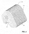
- FIG. 2 is a perspective view showing a 3-D computerized model of the airbag in a fully-inflated configuration according to an embodiment of the present invention
- FIG. 3 is a diagram showing a scheme of unfolding a 3-D computerized model to a 2-D mesh model, according to an embodiment of the present invention
- FIGS. 4-5 shows a 2-D mesh models that are unfolded from the 3-D computerized model of FIG. 2
- FIG. 6 is a diagram showing an exemplary warp and weft definitions to be used in a fabric material coordinate system, according to an embodiment of the present invention.
- FIG. 7 is a function diagram showing salient components of an exemplary computer, in which one embodiment of the present invention may be implemented.
- FIG. 1 is a flowchart illustrating an exemplary process 100 of designing an airbag used as a vehicle safety device for increasing occupant safety in an automobile collision, in particular, creating 2-D mesh models of fabric panels of an airbag from a 3-D computerized model of the airbag in fully-inflated configuration, according to an embodiment of the present invention.
- Process 100 is preferably understood in conjunction with the previous figures and is implemented in software.
- Process 100 starts by receiving a 3-D computerized model (e.g., finite element analysis model) of an airbag in a fully-inflated configuration at step 102.
- the 3-D computerized model comprises a plurality of nodes and a plurality of shell finite elements (e.g., quadrilateral element, triangular element, etc.). Since the airbag is made of a plurality of fabric panels, each shell finite element is further designated to one of the fabric panels. In other words, each fabric panel contains a portion of the shell elements of the 3-D computerized model.
- a perspective view of an exemplary 3-D computerized model 200 of an airbag in its fully-inflated configuration is shown in FIG. 2 .
- Airbag 200 is made of three fabric panels 201, 202, 203 (the third panel 203 is hidden).
- a 2-D mesh model is created for each fabric panel by unfolding those shell finite elements representing the particular fabric panel from a first orientation in the fully-inflated configuration to a second orientation of a flat geometry.
- the first orientation is defined by a set of node numbers in the 3-D computerized model
- the second orientation is defined by another set of node numbers of the 2-D mesh model.
- Element identifier e.g., element number, element label
- FIG. 3 shows an exemplary 3-D computerized model 302 unfolded to a 2-D mesh model 304.
- the 3-D computerized model 302 represents a portion of curved dome structure defined by a set of nodes 312 having a first set of node numbers.
- the 2-D mesh model 304 represents the flattened 3-D computerized model 302 and defined by another set of nodes 314 having a second set of node numbers.
- 2-D mesh models 401 and 502 of the fabric panels 201 and 202 are shown in FIG. 4 and FIG. 5 , respectively.
- Process 100 moves then to decision 106, it is determined whether the total area of the 2-D mesh model is within a tolerance when comparing with the total surface area of those shell elements representing the particular fabric panel of the 3-D computerized model.
- the tolerance is established with known techniques, for example, a percentage of difference defined by user. If "no", process 100 moves to step 108, in which the 2-D mesh model is adjusted to match the total surface area.
- decision 110 if there are more panels in the airbag to be unfolded, process 100 moves back to step 104 to repeat the process for another fabric panel. Otherwise, process 100 moves to step 112, the 2-D mesh models are orientated to respective fabric material coordinate system of warp and weft for determining manufacturability.
- the area 408 ( FIG. 4 ) occupied by the airbag vents is removed from corresponding 2-D mesh model before process 100 ends.
- An exemplary warp 602 and weft 604 definition is shown in FIG. 6
- the present invention is directed towards one or more computer systems capable of carrying out the functionality described herein.
- An example of a computer system 700 is shown in FIG. 7 .
- the computer system 700 includes one or more processors, such as processor 704.
- the processor 704 is connected to a computer system internal communication bus 702.
- Various software embodiments are described in terms of this exemplary computer system. After reading this description, it will become apparent to a person skilled in the relevant art(s) how to implement the invention using other computer systems and/or computer architectures.
- Computer system 700 also includes a main memory 708, preferably random access memory (RAM), and may also include a secondary memory 710.
- the secondary memory 710 may include, for example, one or more hard disk drives 712 and/or one or more removable storage drives 714, representing a floppy disk drive, a magnetic tape drive, an optical disk drive, etc.
- the removable storage drive 714 reads from and/or writes to a removable storage unit 718 in a well-known manner.
- Removable storage unit 718 represents a floppy disk, magnetic tape, optical disk, etc. which is read by and written to by removable storage drive 714.
- the removable storage unit 718 includes a computer usable storage medium having stored therein computer software and/or data.
- secondary memory 710 may include other similar means for allowing computer programs or other instructions to be loaded into computer system 700.
- Such means may include, for example, a removable storage unit 722 and an interface 720.
- Examples of such may include a program cartridge and cartridge interface (such as that found in video game devices), a removable memory chip (such as an Erasable Programmable Read-Only Memory (EPROM), Universal Serial Bus (USB) flash memory, or PROM) and associated socket, and other removable storage units 722 and interfaces 720 which allow software and data to be transferred from the removable storage unit 722 to computer system 700.
- Computer system 700 is controlled and coordinated by operating system (OS) software, which performs tasks such as process scheduling, memory management, networking and I/O services.
- OS operating system
- Communications interface 724 allows software and data to be transferred between computer system 700 and external devices.
- Examples of communications interface 724 may include a modem, a network interface (such as an Ethernet card), a communications port, a Personal Computer Memory Card International Association (PCMCIA) slot and card, etc.
- the computer 700 communicates with other computing devices over a data network based on a special set of rules (i.e., a protocol).
- a protocol i.e., a protocol
- One of the common protocols is TCP/IP (Transmission Control Protocol/Internet Protocol) commonly used in the Internet.
- TCP/IP Transmission Control Protocol/Internet Protocol
- the communication interface 724 manages the assembling of a data file into smaller packets that are transmitted over the data network or reassembles received packets into the original data file.
- the communication interface 724 handles the address part of each packet so that it gets to the right destination or intercepts packets destined for the computer 700.
- the terms "computer program medium” and “computer usable medium” are used to generally refer to media such as removable storage drive 714, and/or a hard disk installed in hard disk drive 712. These computer program products are means for providing software to computer system 700. The invention is directed to such computer program products.
- the computer system 700 may also include an input/output (I/O) interface 730, which provides the computer system 700 to access monitor, keyboard, mouse, printer, scanner, plotter, and alike.
- I/O input/output
- Computer programs are stored as application modules 706 in main memory 708 and/or secondary memory 710. Computer programs may also be received via communications interface 724. Such computer programs, when executed, enable the computer system 700 to perform the features of the present invention as discussed herein. In particular, the computer programs, when executed, enable the processor 704 to perform features of the present invention. Accordingly, such computer programs represent controllers of the computer system 700.
- the software may be stored in a computer program product and loaded into computer system 700 using removable storage drive 714, hard drive 712, or communications interface 724.
- the main memory 708 may be loaded with one or more application modules 706 that can be executed by one or more processors 704 with or without a user input through the I/O interface 730 to achieve desired tasks.
- the results are computed and stored in the secondary memory 710 (i.e., hard disk drive 712).
- the status of the finite element analysis is reported to the user via the I/O interface 730 either in a text or in a graphical representation.
- an application module 706 is configured to facilitate the creation of the 2-D mesh models from a 3-D computerized model of a fully-inflated airbag.
- the application module 706 further allows the 2-D mesh models to be oriented with a fabric material coordinate system.
- the application module 706 is configured to facilitate the removal of airbag vent area from the 2-D mesh models.
Landscapes
- Engineering & Computer Science (AREA)
- Physics & Mathematics (AREA)
- Theoretical Computer Science (AREA)
- Computer Hardware Design (AREA)
- Evolutionary Computation (AREA)
- Geometry (AREA)
- General Engineering & Computer Science (AREA)
- General Physics & Mathematics (AREA)
- Air Bags (AREA)
Abstract
Systems and methods for numerically creating corresponding 2-D mesh models for a plurality of airbag fabric panels from a 3-D computerized model of a fully-inflated airbag are disclosed. The 3-D computerized model comprises a plurality of nodes and a plurality of shell finite elements. Each shell element is categorized as to which one of a plurality of fabric panels that form the airbag it belongs. Each fabric panel occupies a continuous surface area of the airbag. Shell finite elements of a particular fabric panel are unfolded to a 2-D mesh one fabric panel at a time. The total surface area of a particular fabric panel is compared with the total area of the corresponding 2-D model. The 2-D mesh model is adjusted until the areas are within a predetermined tolerance. The final "total-area-matched" 2-D mesh model is further orientated to a fabric material coordinate system of warp and weft for determining manufacturability.
Description
- The present invention generally relates to designing of an airbag, which is a vehicle safety device for increasing occupant safety during an automobile collision, more particularly to methods and systems for creating a plurality of two-dimensional mesh models (e.g., finite element analysis model) of fabric panels that form an airbag from a three-dimensional computerized model of the airbag in a fully-inflated configuration.
- Airbag is made of a plurality of fabric panels stitched together and installed in an automobile to provide an occupant restraint in an automobile collision. Airbag contains a flexible envelope designed to inflate rapidly in a car crash, to prevent vehicle occupants from striking interior objects such as the steering wheel or a window. Modern vehicles may contain multiple airbags in various side and frontal locations of the passenger seating positions and sensors may deploy one or more airbags in an impact zone at variable rates based on the type and severity of impact.
- With advent of computing technologies, airbag is designed using computer aided engineering analysis (e.g., a finite element analysis (FEA) collaborated between two groups of engineers/designers. The first group is responsible for protecting a vehicle occupant when airbag is fully-inflated in an automobile crash, while the second group for manufacturability of airbag. To satisfy these design goals, a three-dimensional fully-inflated geometry of an airbag is used by the first group while the two-dimensional flat geometry of the panels by the second group.
- Since the design flow is from the first group to the second group, it would therefore be desirable to have methods and systems for numerically creating corresponding two-dimensional models of fabric panels from a three-dimensional computerized model of the airbag in a fully-inflated configuration.
- Systems, methods and software product for numerically creating corresponding two-dimensional (2-D) mesh models of a plurality of fabric panels that form an airbag from a three-dimensional (3-D) computerized model of a fully-inflated airbag are disclosed.
- According to one exemplary embodiment of the present invention, a 3-D computerized model (e.g., finite element analysis model, grid model, etc.) of a fully-inflated airbag is defined. The 3-D computerized model comprises a plurality of nodes and a plurality of shell finite elements. Each shell element is designated to one of a plurality of fabric panels that form the airbag it belongs. Each fabric panel occupies a continuous surface area of the airbag. Shell finite elements of a particular fabric panel in respective three-dimensional topologies or geometries are unfolded to a two-dimensional mesh model one fabric panel at a time. The total surface area of a particular fabric panel is compared with the total area of the corresponding 2-D mesh model. Adjust the 2-D mesh model until the areas are within a predetermined tolerance. The final "total-area-matched" 2-D mesh model is further orientated to a fabric material coordinate system of warp and weft for determining manufacturability.
- According to another aspect, the identifier for each shell element (e.g., element number, element label, etc.) is kept the same in the 3-D and 2-D models, while the identifiers for nodes (e.g., node number, node label, etc.) are different in two models.
- According to yet another aspect, the area for airbag vents is included in the unfolding operation originally and then removed from the final 2-D mesh model, whose area matches the surface area of the 3-D model.
- These and other features, aspects, and advantages of the present invention will be better understood with regard to the following description, appended claims, and accompanying drawings as follows:
-
FIG. 1 is a flowchart illustrating an exemplary process of creating 2-D mesh models of airbag fabric panels from a fully-inflated 3-D computerized model, according to an embodiment of the present invention -
FIG. 2 is a perspective view showing a 3-D computerized model of the airbag in a fully-inflated configuration according to an embodiment of the present invention; -
FIG. 3 is a diagram showing a scheme of unfolding a 3-D computerized model to a 2-D mesh model, according to an embodiment of the present invention; -
FIGS. 4-5 shows a 2-D mesh models that are unfolded from the 3-D computerized model ofFIG. 2 -
FIG. 6 is a diagram showing an exemplary warp and weft definitions to be used in a fabric material coordinate system, according to an embodiment of the present invention; and -
FIG. 7 is a function diagram showing salient components of an exemplary computer, in which one embodiment of the present invention may be implemented. -
FIG. 1 is a flowchart illustrating anexemplary process 100 of designing an airbag used as a vehicle safety device for increasing occupant safety in an automobile collision, in particular, creating 2-D mesh models of fabric panels of an airbag from a 3-D computerized model of the airbag in fully-inflated configuration, according to an embodiment of the present invention.Process 100 is preferably understood in conjunction with the previous figures and is implemented in software. -
Process 100 starts by receiving a 3-D computerized model (e.g., finite element analysis model) of an airbag in a fully-inflated configuration atstep 102. The 3-D computerized model comprises a plurality of nodes and a plurality of shell finite elements (e.g., quadrilateral element, triangular element, etc.). Since the airbag is made of a plurality of fabric panels, each shell finite element is further designated to one of the fabric panels. In other words, each fabric panel contains a portion of the shell elements of the 3-D computerized model. A perspective view of an exemplary 3-Dcomputerized model 200 of an airbag in its fully-inflated configuration is shown inFIG. 2 .Airbag 200 is made of threefabric panels third panel 203 is hidden). - Next, at
step 104, a 2-D mesh model is created for each fabric panel by unfolding those shell finite elements representing the particular fabric panel from a first orientation in the fully-inflated configuration to a second orientation of a flat geometry. The first orientation is defined by a set of node numbers in the 3-D computerized model, while the second orientation is defined by another set of node numbers of the 2-D mesh model. Element identifier (e.g., element number, element label) of each unfolded finite element is retained or remains to be the same. As an example of unfolding operation of a 3-D object to 2-D,FIG. 3 shows an exemplary 3-Dcomputerized model 302 unfolded to a 2-D mesh model 304. The 3-Dcomputerized model 302 represents a portion of curved dome structure defined by a set ofnodes 312 having a first set of node numbers. The 2-D mesh model 304 represents the flattened 3-Dcomputerized model 302 and defined by another set ofnodes 314 having a second set of node numbers. 2-D mesh models fabric panels FIG. 4 andFIG. 5 , respectively. -
Process 100 moves then todecision 106, it is determined whether the total area of the 2-D mesh model is within a tolerance when comparing with the total surface area of those shell elements representing the particular fabric panel of the 3-D computerized model. The tolerance is established with known techniques, for example, a percentage of difference defined by user. If "no",process 100 moves tostep 108, in which the 2-D mesh model is adjusted to match the total surface area. Next, atdecision 110, if there are more panels in the airbag to be unfolded,process 100 moves back tostep 104 to repeat the process for another fabric panel. Otherwise,process 100 moves tostep 112, the 2-D mesh models are orientated to respective fabric material coordinate system of warp and weft for determining manufacturability. Finally, atstep 114, the area 408 (FIG. 4 ) occupied by the airbag vents is removed from corresponding 2-D mesh model beforeprocess 100 ends. Anexemplary warp 602 andweft 604 definition is shown inFIG. 6 - According to one aspect, the present invention is directed towards one or more computer systems capable of carrying out the functionality described herein. An example of a
computer system 700 is shown inFIG. 7 . Thecomputer system 700 includes one or more processors, such asprocessor 704. Theprocessor 704 is connected to a computer system internal communication bus 702. Various software embodiments are described in terms of this exemplary computer system. After reading this description, it will become apparent to a person skilled in the relevant art(s) how to implement the invention using other computer systems and/or computer architectures. -
Computer system 700 also includes amain memory 708, preferably random access memory (RAM), and may also include asecondary memory 710. Thesecondary memory 710 may include, for example, one or morehard disk drives 712 and/or one or moreremovable storage drives 714, representing a floppy disk drive, a magnetic tape drive, an optical disk drive, etc. Theremovable storage drive 714 reads from and/or writes to aremovable storage unit 718 in a well-known manner.Removable storage unit 718, represents a floppy disk, magnetic tape, optical disk, etc. which is read by and written to byremovable storage drive 714. As will be appreciated, theremovable storage unit 718 includes a computer usable storage medium having stored therein computer software and/or data. - In alternative embodiments,
secondary memory 710 may include other similar means for allowing computer programs or other instructions to be loaded intocomputer system 700. Such means may include, for example, aremovable storage unit 722 and aninterface 720. Examples of such may include a program cartridge and cartridge interface (such as that found in video game devices), a removable memory chip (such as an Erasable Programmable Read-Only Memory (EPROM), Universal Serial Bus (USB) flash memory, or PROM) and associated socket, and otherremovable storage units 722 andinterfaces 720 which allow software and data to be transferred from theremovable storage unit 722 tocomputer system 700. In general,Computer system 700 is controlled and coordinated by operating system (OS) software, which performs tasks such as process scheduling, memory management, networking and I/O services. - There may also be a
communications interface 724 connecting to the bus 702. Communications interface 724 allows software and data to be transferred betweencomputer system 700 and external devices. Examples ofcommunications interface 724 may include a modem, a network interface (such as an Ethernet card), a communications port, a Personal Computer Memory Card International Association (PCMCIA) slot and card, etc. Thecomputer 700 communicates with other computing devices over a data network based on a special set of rules (i.e., a protocol). One of the common protocols is TCP/IP (Transmission Control Protocol/Internet Protocol) commonly used in the Internet. In general, thecommunication interface 724 manages the assembling of a data file into smaller packets that are transmitted over the data network or reassembles received packets into the original data file. In addition, thecommunication interface 724 handles the address part of each packet so that it gets to the right destination or intercepts packets destined for thecomputer 700. In this document, the terms "computer program medium" and "computer usable medium" are used to generally refer to media such asremovable storage drive 714, and/or a hard disk installed inhard disk drive 712. These computer program products are means for providing software tocomputer system 700. The invention is directed to such computer program products. - The
computer system 700 may also include an input/output (I/O)interface 730, which provides thecomputer system 700 to access monitor, keyboard, mouse, printer, scanner, plotter, and alike. - Computer programs (also called computer control logic) are stored as
application modules 706 inmain memory 708 and/orsecondary memory 710. Computer programs may also be received viacommunications interface 724. Such computer programs, when executed, enable thecomputer system 700 to perform the features of the present invention as discussed herein. In particular, the computer programs, when executed, enable theprocessor 704 to perform features of the present invention. Accordingly, such computer programs represent controllers of thecomputer system 700. - In an embodiment where the invention is implemented using software, the software may be stored in a computer program product and loaded into
computer system 700 usingremovable storage drive 714,hard drive 712, orcommunications interface 724. Theapplication module 706, when executed by theprocessor 704, causes theprocessor 704 to perform the functions of the invention as described herein. - The
main memory 708 may be loaded with one ormore application modules 706 that can be executed by one ormore processors 704 with or without a user input through the I/O interface 730 to achieve desired tasks. In operation, when at least oneprocessor 704 executes one of theapplication modules 706, the results are computed and stored in the secondary memory 710 (i.e., hard disk drive 712). The status of the finite element analysis is reported to the user via the I/O interface 730 either in a text or in a graphical representation. - In one embodiment, an
application module 706 is configured to facilitate the creation of the 2-D mesh models from a 3-D computerized model of a fully-inflated airbag. Theapplication module 706 further allows the 2-D mesh models to be oriented with a fabric material coordinate system. In another embodiment, theapplication module 706 is configured to facilitate the removal of airbag vent area from the 2-D mesh models. - Although the present invention has been described with reference to specific embodiments thereof, these embodiments are merely illustrative, and not restrictive of, the present invention. Various modifications or changes to the specifically disclosed exemplary embodiments will be suggested to persons skilled in the art. For example, whereas a particular type of airbag has been shown and described for carrying out one embodiment of the present invention, other types of airbag may be used for accomplishing the same. Further, whereas three fabric panels have been shown and described to form an airbag, other number of panels can be used for accomplishing the same. Finally, 3-D computerized model and 2-D mesh model have been shown and described as examples, models with other mesh densities or shapes can be used for achieving objectives of the present invention. In summary, the scope of the invention should not be restricted to the specific exemplary embodiments disclosed herein, and all modifications that are readily suggested to those of ordinary skill in the art should be included within the spirit and purview of this application and scope of the appended claims.
Claims (12)
- A method of designing an airbag used as a vehicle safety device for increasing occupant safety in an automobile collision, said method comprising:receiving a three-dimensional (3-D) computerized model representing an airbag in a fully-inflated configuration, said 3-D computerized model containing a plurality of shell finite elements, wherein each of the shell finite elements is designated to one of a plurality of fabric panels that form the airbag;creating a two-dimensional (2-D) mesh model using those shell finite elements being designated to said each of the fabric panels by unfolding each of said those shell finite elements from a first orientation in the fully-inflated configuration to a second orientation in a flat geometry of the 2-D mesh model;adjusting the 2-D mesh model such that total area of the 2-D mesh model is within a tolerance when comparing with total surface area of said those shell elements being designated to said each of the fabric panels; andorientating the 2-D mesh model with a fabric material coordinate system of warp and weft that is suitable for determining manufacturability.
- The method of claim 1, further comprises retaining an element identifier of said each of said those shell elements of the 3-D computerized model in the 2-D mesh model.
- The method of claim 4, wherein said each of said those shell elements is defined by a first set of node in the 3-D computerized model and a second set of node numbers in the 2-D mesh model.
- The method of claim 4, wherein the first orientation is defined in the first set of node numbers, while the second orientation is defined in the second set of node numbers.
- The method of claim 1, wherein the shell finite elements comprise quadrilateral elements.
- The method of claim 5, wherein the shell finite elements further comprise triangular elements.
- The method of claim 1, further comprises removing area occupied by airbag vents from the 2-D mesh model.
- A system for designing an airbag used as a vehicle safety device for increasing occupant safety in an automobile collision, said system comprising:a main memory for storing computer readable code for an application module;at least one processor coupled to the main memory, said at least one processor executing the computer readable code in the main memory to cause the application module to perform operations by a method of:receiving a three-dimensional (3-D) computerized model representing an airbag in a fully-inflated configuration, said 3-D computerized model containing a plurality of shell finite elements, wherein each of the shell finite elements is designated to one of a plurality of fabric panels that form the airbag;creating a two-dimensional (2-D) mesh model using those shell finite elements being designated to said each of the fabric panels by unfolding each of said those shell finite elements from a first orientation in the fully-inflated configuration to a second orientation in a flat geometry of the 2-D mesh model;adjusting the 2-D mesh model such that total area of the 2-D mesh model is within a tolerance when comparing with total surface area of said those shell elements being designated to said each of the fabric panels; and orientating the 2-D mesh model with a fabric material coordinate system of warp and weft that is suitable for determining manufacturability.
- The system of claim 8, further comprises retaining an element identifier of said each of said those shell elements of the 3-D computerized model in the 2-D mesh model.
- The system of claim 9, wherein said each of said those shell elements is defined by a first set of node numbers in the 3-D computerized model and a second set of node numbers in the 2-D mesh model.
- The system of claim 8, further comprises removing area occupied by airbag vents from the 2-D mesh model.
- A computer readable storage medium containing instructions, when executed in a computer system, for designing an airbag used as a vehicle safety device for increasing occupant safety in an automobile collision by a method comprising:receiving a three-dimensional (3-D) computerized model representing an airbag in a fully-inflated configuration, said 3-D computerized model containing a plurality of shell finite elements, wherein each of the shell finite elements is designated to one of a plurality of fabric panels that form the airbag;creating a two-dimensional (2-D) mesh model using those shell finite elements being designated to said each of the fabric panels by unfolding each of said those shell finite elements from a first orientation in the fully-inflated configuration to a second orientation in a flat geometry of the 2-D mesh model;adjusting the 2-D mesh model such that total area of the 2-D mesh model is within a tolerance when comparing with total surface area of said those shell elements being designated to said each of the fabric panels; andorientating the 2-D mesh model with a fabric material coordinate system of warp and weft that is suitable for determining manufacturability.
Applications Claiming Priority (1)
| Application Number | Priority Date | Filing Date | Title |
|---|---|---|---|
| US13/333,087 US20130166253A1 (en) | 2011-12-21 | 2011-12-21 | Systems and Methods of Designing Airbag |
Publications (1)
| Publication Number | Publication Date |
|---|---|
| EP2608086A2 true EP2608086A2 (en) | 2013-06-26 |
Family
ID=47221135
Family Applications (1)
| Application Number | Title | Priority Date | Filing Date |
|---|---|---|---|
| EP12188465.4A Withdrawn EP2608086A2 (en) | 2011-12-21 | 2012-10-15 | Systems and Methods of Designing Airbag |
Country Status (4)
| Country | Link |
|---|---|
| US (1) | US20130166253A1 (en) |
| EP (1) | EP2608086A2 (en) |
| JP (1) | JP2013131214A (en) |
| CN (1) | CN103177148A (en) |
Families Citing this family (7)
| Publication number | Priority date | Publication date | Assignee | Title |
|---|---|---|---|---|
| CN103544347B (en) * | 2013-10-17 | 2016-07-06 | 南京航空航天大学 | A kind of finite element method of inflating expanded fabric work process |
| FR3016982B1 (en) * | 2014-01-29 | 2016-02-19 | Snecma | METHOD FOR SIMULATING THE SHAPING OF A TEXTILE STRIP ON A REVOLUTION MOLD |
| JP6385162B2 (en) * | 2014-06-26 | 2018-09-05 | ダイハツ工業株式会社 | Vehicle side airbag design method |
| JP6385161B2 (en) * | 2014-06-26 | 2018-09-05 | ダイハツ工業株式会社 | Vehicle side airbag design method |
| US9663062B2 (en) * | 2015-10-16 | 2017-05-30 | Autoliv Asp, Inc. | Airbags including internal tethers and methods of forming the same |
| CN109204217A (en) * | 2018-08-02 | 2019-01-15 | 延锋百利得(上海)汽车安全系统有限公司 | Obtain method, apparatus, computer equipment and the storage medium of the inflation data of safety air bag |
| JP7565518B2 (en) * | 2020-11-06 | 2024-10-11 | 学校法人トヨタ学園 | Method for creating planar development data suitable for a preform of a three-dimensional fiber-reinforced composite shell structure, program for creating the planar development data, and method for producing a preform of a three-dimensional fiber-reinforced composite shell structure |
Family Cites Families (4)
| Publication number | Priority date | Publication date | Assignee | Title |
|---|---|---|---|---|
| US6819966B1 (en) * | 2003-12-06 | 2004-11-16 | Paul E. Haeberli | Fabrication of free form structures from planar materials |
| GB2420643B (en) * | 2004-11-30 | 2011-01-12 | Innoval Technology Ltd | Fabric modelling |
| US8392162B2 (en) * | 2006-02-02 | 2013-03-05 | Ford Global Technologies | Vehicular supplemental restraint device simulation using finite element modeling |
| US8648855B2 (en) * | 2010-01-12 | 2014-02-11 | Daedal Doodle, LLC | Methods for creating developable surfaces |
-
2011
- 2011-12-21 US US13/333,087 patent/US20130166253A1/en not_active Abandoned
-
2012
- 2012-09-27 CN CN2012103659539A patent/CN103177148A/en active Pending
- 2012-10-15 EP EP12188465.4A patent/EP2608086A2/en not_active Withdrawn
- 2012-11-16 JP JP2012251927A patent/JP2013131214A/en active Pending
Non-Patent Citations (1)
| Title |
|---|
| None |
Also Published As
| Publication number | Publication date |
|---|---|
| JP2013131214A (en) | 2013-07-04 |
| CN103177148A (en) | 2013-06-26 |
| US20130166253A1 (en) | 2013-06-27 |
Similar Documents
| Publication | Publication Date | Title |
|---|---|---|
| EP2608086A2 (en) | Systems and Methods of Designing Airbag | |
| US8180605B1 (en) | Methods and systems for creating a smooth contact-impact interface in finite element analysis | |
| EP2390801A1 (en) | Hybrid element enabling finite element/smoothed particle hydrodynamics coupling | |
| US8374833B2 (en) | Hybrid element enabling solid/SPH coupling effect | |
| CN107256289A (en) | The method for building up of car crass reduced parameter FEM model | |
| US20130185030A1 (en) | Numerically simulating structural behaviors of a product using explicit finite element analysis with a combined technique of mass scaling and subcycling | |
| US20180285488A1 (en) | Systems And Methods Of Designing Geometry Of Tool Set In A Numerical Simulation Of Sheet Metal Forming Operations Including Springback Compensation | |
| KR102131304B1 (en) | Systems and Methods of Numerically Simulating Structural Behaviors of Airbag Made of Coated Fabric Material | |
| EP2202659A2 (en) | Method of simulating impact events in a multi-processor computer system | |
| EP2273397A1 (en) | Numerical simulation of airflow within porous materials | |
| US20110282637A1 (en) | Numerical simulation of airflow within porous materials | |
| CN109388840B (en) | Special programming computer for numerical simulation of metal forming processes with predefined load paths and corresponding grid adjustment schemes | |
| CN106933617A (en) | Automobile software adaptation system and its adaptation method | |
| US8855976B2 (en) | Numerically simulating structural behaviors of a product using explicit finite element analysis with a mass scaling enhanced subcycling technique | |
| US20110231163A1 (en) | Methods and systems for numerically predicting surface imperfections on stamped sheet metal parts | |
| CN113146621B (en) | Robot control method, device, robot, and computer-readable storage medium | |
| US9292632B2 (en) | Methods and systems for providing detailed rigid wall force summary in a time-marching simulation of a vehicle colliding with a rigid wall | |
| CN114970288A (en) | Simulation Modeling Method of Collision Finite Element Dummy Skin Parts | |
| US7590514B1 (en) | Method and system for simulating inflation of an enclosed volume with flexible boundary using gas particles | |
| EP3124255B1 (en) | Method for adjusting printing head usage amount of 3d printer and control device | |
| Fründ et al. | Using augmented reality technology to support the automobile development | |
| US20080076274A1 (en) | Device design supporting method, program, and system | |
| US20110208497A1 (en) | Computer aided design method for creating a surface in a complex system | |
| KR20140100412A (en) | Contact surface definition creation involving low order and quadratic finite elements in a numerical simulation of an impact event | |
| US8577656B1 (en) | Methods and systems for numerically simulating inflation of an airbag configured with a plurality of connected flexible-boundary volumes |
Legal Events
| Date | Code | Title | Description |
|---|---|---|---|
| AK | Designated contracting states |
Kind code of ref document: A2 Designated state(s): AL AT BE BG CH CY CZ DE DK EE ES FI FR GB GR HR HU IE IS IT LI LT LU LV MC MK MT NL NO PL PT RO RS SE SI SK SM TR |
|
| AX | Request for extension of the european patent |
Extension state: BA ME |
|
| PUAI | Public reference made under article 153(3) epc to a published international application that has entered the european phase |
Free format text: ORIGINAL CODE: 0009012 |
|
| STAA | Information on the status of an ep patent application or granted ep patent |
Free format text: STATUS: THE APPLICATION IS DEEMED TO BE WITHDRAWN |
|
| 18D | Application deemed to be withdrawn |
Effective date: 20160503 |