EP2607912A2 - Low-voltage testing device for high-voltage frequency converter of serial superposition voltage type - Google Patents
Low-voltage testing device for high-voltage frequency converter of serial superposition voltage type Download PDFInfo
- Publication number
- EP2607912A2 EP2607912A2 EP12198283.9A EP12198283A EP2607912A2 EP 2607912 A2 EP2607912 A2 EP 2607912A2 EP 12198283 A EP12198283 A EP 12198283A EP 2607912 A2 EP2607912 A2 EP 2607912A2
- Authority
- EP
- European Patent Office
- Prior art keywords
- voltage
- power
- unit
- monitoring box
- frequency converter
- Prior art date
- Legal status (The legal status is an assumption and is not a legal conclusion. Google has not performed a legal analysis and makes no representation as to the accuracy of the status listed.)
- Granted
Links
- 238000012360 testing method Methods 0.000 title claims abstract description 17
- 238000012544 monitoring process Methods 0.000 claims abstract description 26
- 239000013307 optical fiber Substances 0.000 claims abstract description 6
- 238000013461 design Methods 0.000 abstract description 2
- 230000007774 longterm Effects 0.000 abstract description 2
- 238000012545 processing Methods 0.000 description 7
- 238000010586 diagram Methods 0.000 description 4
- 230000003287 optical effect Effects 0.000 description 4
- 238000000034 method Methods 0.000 description 3
- 230000003247 decreasing effect Effects 0.000 description 1
- 238000001514 detection method Methods 0.000 description 1
- 238000003745 diagnosis Methods 0.000 description 1
- 230000000694 effects Effects 0.000 description 1
- 238000013100 final test Methods 0.000 description 1
- 238000002955 isolation Methods 0.000 description 1
- 238000004519 manufacturing process Methods 0.000 description 1
- 238000005272 metallurgy Methods 0.000 description 1
- 230000002093 peripheral effect Effects 0.000 description 1
- 238000004088 simulation Methods 0.000 description 1
- XLYOFNOQVPJJNP-UHFFFAOYSA-N water Substances O XLYOFNOQVPJJNP-UHFFFAOYSA-N 0.000 description 1
- 238000004804 winding Methods 0.000 description 1
Images

Classifications
-
- G—PHYSICS
- G01—MEASURING; TESTING
- G01R—MEASURING ELECTRIC VARIABLES; MEASURING MAGNETIC VARIABLES
- G01R31/00—Arrangements for testing electric properties; Arrangements for locating electric faults; Arrangements for electrical testing characterised by what is being tested not provided for elsewhere
- G01R31/28—Testing of electronic circuits, e.g. by signal tracer
-
- G—PHYSICS
- G01—MEASURING; TESTING
- G01R—MEASURING ELECTRIC VARIABLES; MEASURING MAGNETIC VARIABLES
- G01R31/00—Arrangements for testing electric properties; Arrangements for locating electric faults; Arrangements for electrical testing characterised by what is being tested not provided for elsewhere
- G01R31/40—Testing power supplies
- G01R31/42—AC power supplies
Definitions
- the present utility model relates to frequency converter technique, and more particularly, to a low-voltage testing device for a high-voltage frequency converter of a serial superposition voltage type.
- a main controller (monitoring box) of a frequency converter has a unit-combined structure, and its core is a CPU unit having double CPUs communicating with an interface board and phase control boards A, B and C via a bus.
- An operation command, a frequency setting signal, an electric machine current and voltage, and so on may be accepted from an analog input interface.
- a CPU board calculates control information and status information according to the operation command, the setting signal and other input signals.
- the phase control boards A, B and C accept the control information from the CPU board, generate PWM control signals and send control optical signals to a power unit via an electric-to-optical transducer.
- An acknowledgement signal from the power unit is converted to an electric signal in the phase control boards A, B and C, subjected to processing and then sent to the CPU board for processing.
- the status information may be sent out through the interface board and an interface sub-template.
- Debugging of the main controller is very important for the high-voltage frequency converter, however, existing debugging means is simplified, and an effect of testing can not be achieved actually under self-operating by simulating the high voltage in a case of shielding relevant status information of the power unit. It is much more troublesome with being tested under high voltage condition due to hugeness of the equipment, inconvenience of connections of high voltage wires and loads and high cost, and more problems occur when there are faults and repair is needed.
- An object of the utility model is to provide a low-voltage testing device for a high-voltage frequency converter of a serial superposition voltage type.
- the object of the utility model is realized in that the testing device is constituted by a tap transformer, a power portion, a monitoring box, an analog interface board, a voltage detecting portion and a remote control portion, in which the tap transformer is connected to the power portion, the power portion is connected to the voltage detecting portion, the monitoring box is connected to the power portion via an optical fiber and the analog interface board is connected to the monitoring box and the remote control portion respectively.
- the utility model further has the following technical features:
- the power portion is divided into three groups, each group being one phase and six power units being connected in series in each phase.
- the monitoring box includes a PWM unit, a FPGA, a CPLD unit, a double-DSP unit, an interface circuit and a touch screen, in which the PWM unit is connected to the FPGA and the CPLD unit, the FPGA and the CPLD unit are connected to the double-DSP unit and the double-DSP unit is connected to the interface circuit and the touch screen respectively.
- the remote control portion includes an AVR control board and an operation panel, the AVR control board being connected to the operation panel.
- the novel low-voltage testing device for the high-voltage frequency converter of the serial superposition voltage type according to the utility model has a simple structure and liable performance, simulates an on-load final test and completes software test of a control system.
- Advantages of the utility model are that MOSFET is used as a power device instead of IGBT, the cost is low and the repair is convenient; each power board represents one unit, and thus the size is small and the operation is convenient; function tests of the system and the monitoring box can be simulated completely; and an input voltage of the system is 380V, and an output thereof is a step wave ranging from 0 to 380V, which belongs to a low voltage platform, and thus the system is safe and reliable.
- the utility model provides a test device having a reasonable cost-performance ratio with respect to conditions in which the existing high-voltage frequency converter has a complicated structure, and thus wiring and debugging are not convenient, and problems occurring in the monitoring equipment will cause faults of the frequency converter or damage of the power units, and so on, and the low-voltage testing platform will be a best choice at this time. It is required that the operating stability of the high-voltage frequency converter should be reliable in order to ensure production to be carried out normally and continuously in industries such as metallurgy, water supply, electric power and so on. After practical checking, the design scheme of the low-voltage testing on the high-voltage frequency converter proposed in the utility model enables liable performance and long term operating, and thus has a wide application prospect in a market.
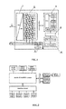
- Fig.1 is a functional block diagram of the whole system of the utility model
- Fig.2 is a functional block diagram of the monitoring box of the utility model
- Fig.4 is a functional block diagram of the remote control portion of the utility model.
- the low-voltage testing device for the high-voltage frequency converter of the serial superposition voltage type according to the utility model is constituted by a tap transformer (1), a power portion (2), a monitoring box (3), an analog interface board (4), a voltage detecting portion (5) and a remote control portion (6), in which the tap transformer (1) is connected to the power portion (2), the power portion (2) is connected to the voltage detecting portion (5), the monitoring box (3) is connected to the power portion (2) via an optical fiber and the analog interface board (4) is connected to the monitoring box (3) and the remote control portion (5) respectively.
- the utility model further has the following technical features.
- the power portion (2) is divided into three groups, each group being one phase and six power units being connected in series in each phase.
- the monitoring box (3) includes a PWM unit, a FPGA, a CPLD unit, a double-DSP unit, an interface circuit and a touch screen, in which the PWM unit is connected to the FPGA and the CPLD unit, the FPGA and the CPLD unit are connected to the double-DSP unit and the double-DSP unit is connected to the interface circuit and the touch screen respectively.
- the remote control portion (6) includes an AVR control board and an operation panel, the AVR control board being connected to the operation panel.
- Embodiment 2 with reference to Fig.1 to Fig.4 , the operating principles of the utility model are as follows:
- the utility model implements a low-voltage frequency converter simulating unit connection in series and multi-superposition.
- Three-phase input voltage of 380V is decreased via an input transformer and is phase-shifted to power the power units in a power unit cabinet.
- the power portion is divided into three groups, each group being one phase, and an output of the power board of each phase is cascaded end to end.
- the control portion performs real time rectification and inversion control and detection on each power board through the optical fiber, and the user needs to set the frequency through an operation interface. Further, the control unit sends control information to the power board for corresponding rectifying and inverting adjustment so as to output a three-phase voltage ranging from about 0 to 380V.
- the monitoring box may receive operation commands and given signals from the touch screen and the remote control portion, process them and then output voltage and frequency setting signals to three phase control units where these signals are converted into PWM control signals, which are converted into optical signals via an electric-to-optical transducer and then sent to each power unit from an optical transmitter port. Acknowledgement information from the power unit is converted into an electric signal via the optical-to-electric transducer, subject to processing and then sent to a main controller for centralized processing.
- the main controller performs operations such as operating control, status analysis, fault diagnosis and so on according to the control commands, the given signals, operating information and the acknowledgement information, performs fault processing according to properties of the faults after having detected the faults, such as system locking, high-voltage tripping and so on, and provides corresponding fault signals.
- the power portion is a single-phase bridge converter which is powered by a secondary winding of an input tap transformer.
- the power portion is controlled by four MOSFETs using a SPWM method after rectification and inversion so as to output AC electric power with variable frequency and variable voltage.
- a plurality of power boards being superposed in series may output three-phase AC electric power with a frequency of 50HZ and a line voltage of 380V so as to drive an AC motor.
- the CPLD detects signals such as a voltage, a current and so on and some status information to be communicably sent to the monitoring box for processing.
- Driving signals and control signals are communicably sent by the monitoring box and processed in a centralized way by the CPLD to drive an H-bridge circuit. Both the control signals and acknowledgement signals from/to the monitoring box are transmitted via optical cables, which may achieve high electrical isolation capability and high anti-EMI (electromagnetic interference) performance.
- the remote control portion is constituted by an AVR single-chip microprocessor as a core element, a DA converter and some peripheral circuits.
- the operation panel sets the frequency and control signals such as start, stop and reset signals and so on to be communicably sent to the AVR single-chip microprocessor for processing, and then a 0-10V DC voltage signal is output from the DA converter and sent to the analog interface board and then to the control portion.
- digital signals such as the high-voltage tripping, reset, emergency stop, auxiliary power source switching-on signals and so on are sent to the control portion, and thus the remote control equipment implements simulation of control systems such as an on-site remote control box, a DCS (distributed control system) and so on.
Landscapes
- Engineering & Computer Science (AREA)
- Physics & Mathematics (AREA)
- General Physics & Mathematics (AREA)
- Power Engineering (AREA)
- General Engineering & Computer Science (AREA)
- Testing Electric Properties And Detecting Electric Faults (AREA)
- Testing Relating To Insulation (AREA)
- Ac-Ac Conversion (AREA)
Abstract
Description
- The present utility model relates to frequency converter technique, and more particularly, to a low-voltage testing device for a high-voltage frequency converter of a serial superposition voltage type.
- A main controller (monitoring box) of a frequency converter has a unit-combined structure, and its core is a CPU unit having double CPUs communicating with an interface board and phase control boards A, B and C via a bus. An operation command, a frequency setting signal, an electric machine current and voltage, and so on may be accepted from an analog input interface. A CPU board calculates control information and status information according to the operation command, the setting signal and other input signals. The phase control boards A, B and C accept the control information from the CPU board, generate PWM control signals and send control optical signals to a power unit via an electric-to-optical transducer. An acknowledgement signal from the power unit is converted to an electric signal in the phase control boards A, B and C, subjected to processing and then sent to the CPU board for processing. The status information may be sent out through the interface board and an interface sub-template. Debugging of the main controller is very important for the high-voltage frequency converter, however, existing debugging means is simplified, and an effect of testing can not be achieved actually under self-operating by simulating the high voltage in a case of shielding relevant status information of the power unit. It is much more troublesome with being tested under high voltage condition due to hugeness of the equipment, inconvenience of connections of high voltage wires and loads and high cost, and more problems occur when there are faults and repair is needed.
- An object of the utility model is to provide a low-voltage testing device for a high-voltage frequency converter of a serial superposition voltage type.
- The object of the utility model is realized in that the testing device is constituted by a tap transformer, a power portion, a monitoring box, an analog interface board, a voltage detecting portion and a remote control portion, in which the tap transformer is connected to the power portion, the power portion is connected to the voltage detecting portion, the monitoring box is connected to the power portion via an optical fiber and the analog interface board is connected to the monitoring box and the remote control portion respectively.
- The utility model further has the following technical features:
- (1) The power portion is divided into three groups, each group being one phase and six power units being connected in series in each phase.
- (2) The monitoring box includes a PWM unit, a FPGA, a CPLD unit, a double-DSP unit, an interface circuit and a touch screen, in which the PWM unit is connected to the FPGA and the CPLD unit, the FPGA and the CPLD unit are connected to the double-DSP unit and the double-DSP unit is connected to the interface circuit and the touch screen respectively.
- (3) The remote control portion includes an AVR control board and an operation panel, the AVR control board being connected to the operation panel.
- The novel low-voltage testing device for the high-voltage frequency converter of the serial superposition voltage type according to the utility model has a simple structure and liable performance, simulates an on-load final test and completes software test of a control system. Advantages of the utility model are that MOSFET is used as a power device instead of IGBT, the cost is low and the repair is convenient; each power board represents one unit, and thus the size is small and the operation is convenient; function tests of the system and the monitoring box can be simulated completely; and an input voltage of the system is 380V, and an output thereof is a step wave ranging from 0 to 380V, which belongs to a low voltage platform, and thus the system is safe and reliable. The utility model provides a test device having a reasonable cost-performance ratio with respect to conditions in which the existing high-voltage frequency converter has a complicated structure, and thus wiring and debugging are not convenient, and problems occurring in the monitoring equipment will cause faults of the frequency converter or damage of the power units, and so on, and the low-voltage testing platform will be a best choice at this time. It is required that the operating stability of the high-voltage frequency converter should be reliable in order to ensure production to be carried out normally and continuously in industries such as metallurgy, water supply, electric power and so on. After practical checking, the design scheme of the low-voltage testing on the high-voltage frequency converter proposed in the utility model enables liable performance and long term operating, and thus has a wide application prospect in a market.
-
Fig.1 is a functional block diagram of the whole system of the utility model; -
Fig.2 is a functional block diagram of the monitoring box of the utility model; -
Fig.3 is a functional block diagram of the power board of the utility model; and -
Fig.4 is a functional block diagram of the remote control portion of the utility model. - Further description of the utility model will be made in conjunction with the accompanying drawings by way of example below.
- Embodiment 1: with reference to
Fig.1 , the low-voltage testing device for the high-voltage frequency converter of the serial superposition voltage type according to the utility model is constituted by a tap transformer (1), a power portion (2), a monitoring box (3), an analog interface board (4), a voltage detecting portion (5) and a remote control portion (6), in which the tap transformer (1) is connected to the power portion (2), the power portion (2) is connected to the voltage detecting portion (5), the monitoring box (3) is connected to the power portion (2) via an optical fiber and the analog interface board (4) is connected to the monitoring box (3) and the remote control portion (5) respectively. - The utility model further has the following technical features.
- The power portion (2) is divided into three groups, each group being one phase and six power units being connected in series in each phase.
- The monitoring box (3) includes a PWM unit, a FPGA, a CPLD unit, a double-DSP unit, an interface circuit and a touch screen, in which the PWM unit is connected to the FPGA and the CPLD unit, the FPGA and the CPLD unit are connected to the double-DSP unit and the double-DSP unit is connected to the interface circuit and the touch screen respectively.
- The remote control portion (6) includes an AVR control board and an operation panel, the AVR control board being connected to the operation panel.
- Embodiment 2: with reference to
Fig.1 to Fig.4 , the operating principles of the utility model are as follows: - (1) principles of the whole system
- The utility model implements a low-voltage frequency converter simulating unit connection in series and multi-superposition. Three-phase input voltage of 380V is decreased via an input transformer and is phase-shifted to power the power units in a power unit cabinet. The power portion is divided into three groups, each group being one phase, and an output of the power board of each phase is cascaded end to end. The control portion performs real time rectification and inversion control and detection on each power board through the optical fiber, and the user needs to set the frequency through an operation interface. Further, the control unit sends control information to the power board for corresponding rectifying and inverting adjustment so as to output a three-phase voltage ranging from about 0 to 380V.
- (2) the monitoring box
- Connection and control between the monitoring box and each power board are implemented by using two optical fibers. The monitoring box may receive operation commands and given signals from the touch screen and the remote control portion, process them and then output voltage and frequency setting signals to three phase control units where these signals are converted into PWM control signals, which are converted into optical signals via an electric-to-optical transducer and then sent to each power unit from an optical transmitter port. Acknowledgement information from the power unit is converted into an electric signal via the optical-to-electric transducer, subject to processing and then sent to a main controller for centralized processing. The main controller performs operations such as operating control, status analysis, fault diagnosis and so on according to the control commands, the given signals, operating information and the acknowledgement information, performs fault processing according to properties of the faults after having detected the faults, such as system locking, high-voltage tripping and so on, and provides corresponding fault signals.
- (3) the power portion
- The power portion is a single-phase bridge converter which is powered by a secondary winding of an input tap transformer. The power portion is controlled by four MOSFETs using a SPWM method after rectification and inversion so as to output AC electric power with variable frequency and variable voltage. A plurality of power boards being superposed in series may output three-phase AC electric power with a frequency of 50HZ and a line voltage of 380V so as to drive an AC motor. The CPLD detects signals such as a voltage, a current and so on and some status information to be communicably sent to the monitoring box for processing. Driving signals and control signals are communicably sent by the monitoring box and processed in a centralized way by the CPLD to drive an H-bridge circuit. Both the control signals and acknowledgement signals from/to the monitoring box are transmitted via optical cables, which may achieve high electrical isolation capability and high anti-EMI (electromagnetic interference) performance.
- (4) The remote control portion
- The remote control portion is constituted by an AVR single-chip microprocessor as a core element, a DA converter and some peripheral circuits. The operation panel sets the frequency and control signals such as start, stop and reset signals and so on to be communicably sent to the AVR single-chip microprocessor for processing, and then a 0-10V DC voltage signal is output from the DA converter and sent to the analog interface board and then to the control portion. Further, digital signals such as the high-voltage tripping, reset, emergency stop, auxiliary power source switching-on signals and so on are sent to the control portion, and thus the remote control equipment implements simulation of control systems such as an on-site remote control box, a DCS (distributed control system) and so on.
Claims (4)
- A low-voltage testing device for a high-voltage frequency converter of a serial superposition voltage type constituted by a tap transformer (1), a power portion (2), a monitoring box (3), an analog interface board (4), a voltage detecting portion (5) and a remote control portion (6), characterized in that the tap transformer (1) is connected to the power portion (2), the power portion (2) is connected to the voltage detecting portion (5), the monitoring box (3) is connected to power portion (2) via an optical fiber and the analog interface board (4) is connected to the monitoring box (3) and the remote control portion (5) respectively.
- The low-voltage testing device for the high-voltage frequency converter of the serial superposition voltage type according to claim 1, characterized in that the power portion (2) is divided into three groups, each group being one phase and six power units being connected in series in each phase.
- The low-voltage testing device for the high-voltage frequency converter of the serial superposition voltage type according to claim 1, characterized in that the monitoring box (3) comprises a PWM unit, a FPGA, a CPLD unit, a double-DSP unit, an interface circuit and a touch screen, wherein the PWM unit is connected to the FPGA and the CPLD unit, the FPGA and the CPLD unit are connected to the double-DSP unit and the double-DSP unit is connected to the interface circuit and the touch screen respectively.
- The low-voltage testing device for the high-voltage frequency converter of the serial superposition voltage type according to claim 1, characterized in that the remote control portion (6) comprises an AVR control board and an operation panel, the AVR control board being connected to the operation panel.
Applications Claiming Priority (1)
| Application Number | Priority Date | Filing Date | Title |
|---|---|---|---|
| CN201120532650.2U CN202404169U (en) | 2011-12-19 | 2011-12-19 | Low voltage testing device of serial voltage-superimposed high voltage converter |
Publications (3)
| Publication Number | Publication Date |
|---|---|
| EP2607912A2 true EP2607912A2 (en) | 2013-06-26 |
| EP2607912A3 EP2607912A3 (en) | 2013-11-13 |
| EP2607912B1 EP2607912B1 (en) | 2015-02-18 |
Family
ID=46701809
Family Applications (1)
| Application Number | Title | Priority Date | Filing Date |
|---|---|---|---|
| EP12198283.9A Not-in-force EP2607912B1 (en) | 2011-12-19 | 2012-12-19 | Low-voltage testing device for high-voltage frequency converter of serial superposition voltage type |
Country Status (3)
| Country | Link |
|---|---|
| US (1) | US8994388B2 (en) |
| EP (1) | EP2607912B1 (en) |
| CN (1) | CN202404169U (en) |
Cited By (2)
| Publication number | Priority date | Publication date | Assignee | Title |
|---|---|---|---|---|
| CN108267659A (en) * | 2018-03-09 | 2018-07-10 | 上海辛格林纳新时达电机有限公司 | A kind of frequency converter test platform and frequency converter test method |
| CN112923863A (en) * | 2021-01-26 | 2021-06-08 | 哈尔滨工程大学 | Secondary frequency conversion fiber grating resonance peak tracking detection system |
Families Citing this family (9)
| Publication number | Priority date | Publication date | Assignee | Title |
|---|---|---|---|---|
| CN202404169U (en) * | 2011-12-19 | 2012-08-29 | 哈尔滨九洲电气股份有限公司 | Low voltage testing device of serial voltage-superimposed high voltage converter |
| WO2014186772A1 (en) * | 2013-05-16 | 2014-11-20 | Keyssa, Inc. | Extremely high frequency converter |
| US9826387B2 (en) * | 2015-11-04 | 2017-11-21 | Abb Technology Oy | Indicating a drive status in communications |
| CN105915028B (en) * | 2016-05-12 | 2018-09-28 | 江苏力普电子科技有限公司 | A kind of power unit cascade type high voltage frequency changer on-the-spot test method |
| CN107621787A (en) * | 2017-08-18 | 2018-01-23 | 海南电网有限责任公司电力科学研究院 | Low pressure APF hardware-in-the-loop test method and systems based on RT LAB |
| CN109450285B (en) * | 2018-11-01 | 2023-10-31 | 北京交通大学 | Rail transit vehicle main-auxiliary integrated mode energy two-way flow auxiliary power supply system |
| CN110112751B (en) * | 2019-06-12 | 2021-06-11 | 南方电网科学研究院有限责任公司 | Valve control interface system capable of expanding series stages of STATCOM (static synchronous compensator) converter chains |
| CN112611977B (en) * | 2020-12-31 | 2023-07-25 | 大禹电气科技股份有限公司 | Performance experiment method and system for high-voltage frequency converter |
| CN115389850B (en) * | 2022-09-20 | 2025-07-08 | 国能神东煤炭集团有限责任公司 | Detection device of frequency converter |
Family Cites Families (10)
| Publication number | Priority date | Publication date | Assignee | Title |
|---|---|---|---|---|
| GB2328028B (en) * | 1997-06-10 | 1999-12-08 | Bcf Designs Ltd | Method and apparatus for testing low-pass frequency-dependent electrical circuits |
| US7362557B2 (en) | 2004-03-30 | 2008-04-22 | Continental Automotive Systems U.S. Inc. | Method, apparatus and article for bi-directional DC/DC power conversion |
| US20080278143A1 (en) * | 2006-12-19 | 2008-11-13 | Lecroy Corporation | Remote Display and Control for Test and Measurement Apparatus |
| US8385504B2 (en) * | 2008-03-06 | 2013-02-26 | Koninklijke Philips Electronics N.V. | DC/AC power inverter control unit of a resonant power converter circuit, in particular a DC/DC converter for use in a high-voltage generator circuitry of a modern computed tomography device or X-ray radiographic system |
| US8118093B2 (en) * | 2008-11-04 | 2012-02-21 | Intelliserv, Llc | Threaded retention device for downhole transmission lines |
| US20100140958A1 (en) * | 2008-12-04 | 2010-06-10 | Searete Llc, A Limited Liability Corporation Of The State Of Delaware | Method for powering devices from intraluminal pressure changes |
| WO2010111412A2 (en) * | 2009-03-24 | 2010-09-30 | Infinirel Corporation | Systems, devices and methods for predicting power electronics failure |
| FI122206B (en) * | 2009-06-30 | 2011-10-14 | Vacon Oyj | Power Transmission Method and Equipment |
| US8531141B2 (en) * | 2011-02-28 | 2013-09-10 | Deere & Company | System for calibrating an electrical control system |
| CN202404169U (en) * | 2011-12-19 | 2012-08-29 | 哈尔滨九洲电气股份有限公司 | Low voltage testing device of serial voltage-superimposed high voltage converter |
-
2011
- 2011-12-19 CN CN201120532650.2U patent/CN202404169U/en not_active Expired - Lifetime
-
2012
- 2012-12-19 US US13/720,394 patent/US8994388B2/en active Active
- 2012-12-19 EP EP12198283.9A patent/EP2607912B1/en not_active Not-in-force
Non-Patent Citations (1)
| Title |
|---|
| None |
Cited By (2)
| Publication number | Priority date | Publication date | Assignee | Title |
|---|---|---|---|---|
| CN108267659A (en) * | 2018-03-09 | 2018-07-10 | 上海辛格林纳新时达电机有限公司 | A kind of frequency converter test platform and frequency converter test method |
| CN112923863A (en) * | 2021-01-26 | 2021-06-08 | 哈尔滨工程大学 | Secondary frequency conversion fiber grating resonance peak tracking detection system |
Also Published As
| Publication number | Publication date |
|---|---|
| EP2607912A3 (en) | 2013-11-13 |
| EP2607912B1 (en) | 2015-02-18 |
| US8994388B2 (en) | 2015-03-31 |
| CN202404169U (en) | 2012-08-29 |
| US20130187663A1 (en) | 2013-07-25 |
Similar Documents
| Publication | Publication Date | Title |
|---|---|---|
| US8994388B2 (en) | Low-voltage testing device for high-voltage frequency converter of serial superposition voltage type | |
| CN103983880B (en) | A kind of grid-connected converter isolated island effect prevention protective capability detection device and method of testing | |
| CN109582004B (en) | Intelligent detection platform | |
| CN204882720U (en) | Intelligent computer direct current system monitoring facilities | |
| CN105974247B (en) | System and method for testing conductive slip ring | |
| CN108535602B (en) | Automatic voltage sag test platform | |
| CN111337778A (en) | A test platform and test method for flexible direct current transmission power module | |
| CN113253079A (en) | Microcomputer type direct current system insulation monitoring test device and method | |
| CN204965174U (en) | Power hardware is at ring test system | |
| CN204068723U (en) | A kind of three-phase voltage sag generating means | |
| CN104407519A (en) | Semi-physical simulation system of AC-DC-AC metallurgy rolling mill transmission system | |
| CN203929928U (en) | The anti-isolated island energy of a kind of grid-connected converter force checking device | |
| CN208092174U (en) | A voltage sag automatic test platform | |
| CN205263212U (en) | Select testing arrangement that closes a floodgate mutually | |
| CN205080239U (en) | Alternator testing system | |
| CN203929995U (en) | A kind of frequency converter PCBA test macro | |
| CN103245842B (en) | 10 ~ 35kV new clothes electric device total system dry run detection method | |
| CN106443256A (en) | Power grid simulator used for harmonic simulation | |
| CN210109234U (en) | Output signal simulation device and secondary load test system | |
| CN204575767U (en) | A kind of STATCOM detection platform of 10kV electric pressure | |
| CN204330904U (en) | A kind of frequency converter test device | |
| CN204556744U (en) | The detection platform of a kind of APF of 380V electric pressure | |
| CN103019231B (en) | A kind of control box for frequency converter ageing test apparatus | |
| CN202870285U (en) | A portable simulation detection device of high-voltage live display apparatuses | |
| CN110133404A (en) | Output signal analog device and secondary loading tests system |
Legal Events
| Date | Code | Title | Description |
|---|---|---|---|
| AK | Designated contracting states |
Kind code of ref document: A2 Designated state(s): AL AT BE BG CH CY CZ DE DK EE ES FI FR GB GR HR HU IE IS IT LI LT LU LV MC MK MT NL NO PL PT RO RS SE SI SK SM TR |
|
| AX | Request for extension of the european patent |
Extension state: BA ME |
|
| PUAI | Public reference made under article 153(3) epc to a published international application that has entered the european phase |
Free format text: ORIGINAL CODE: 0009012 |
|
| PUAL | Search report despatched |
Free format text: ORIGINAL CODE: 0009013 |
|
| AK | Designated contracting states |
Kind code of ref document: A3 Designated state(s): AL AT BE BG CH CY CZ DE DK EE ES FI FR GB GR HR HU IE IS IT LI LT LU LV MC MK MT NL NO PL PT RO RS SE SI SK SM TR |
|
| AX | Request for extension of the european patent |
Extension state: BA ME |
|
| RIC1 | Information provided on ipc code assigned before grant |
Ipc: G01R 31/42 20060101AFI20131010BHEP Ipc: H02M 1/32 20070101ALI20131010BHEP |
|
| 17P | Request for examination filed |
Effective date: 20140513 |
|
| RBV | Designated contracting states (corrected) |
Designated state(s): AL AT BE BG CH CY CZ DE DK EE ES FI FR GB GR HR HU IE IS IT LI LT LU LV MC MK MT NL NO PL PT RO RS SE SI SK SM TR |
|
| GRAP | Despatch of communication of intention to grant a patent |
Free format text: ORIGINAL CODE: EPIDOSNIGR1 |
|
| RIC1 | Information provided on ipc code assigned before grant |
Ipc: G01R 31/42 20060101AFI20140904BHEP Ipc: H02M 1/32 20070101ALI20140904BHEP |
|
| INTG | Intention to grant announced |
Effective date: 20140919 |
|
| GRAS | Grant fee paid |
Free format text: ORIGINAL CODE: EPIDOSNIGR3 |
|
| GRAA | (expected) grant |
Free format text: ORIGINAL CODE: 0009210 |
|
| AK | Designated contracting states |
Kind code of ref document: B1 Designated state(s): AL AT BE BG CH CY CZ DE DK EE ES FI FR GB GR HR HU IE IS IT LI LT LU LV MC MK MT NL NO PL PT RO RS SE SI SK SM TR |
|
| REG | Reference to a national code |
Ref country code: GB Ref legal event code: FG4D |
|
| REG | Reference to a national code |
Ref country code: CH Ref legal event code: EP |
|
| REG | Reference to a national code |
Ref country code: AT Ref legal event code: REF Ref document number: 710872 Country of ref document: AT Kind code of ref document: T Effective date: 20150315 |
|
| REG | Reference to a national code |
Ref country code: IE Ref legal event code: FG4D |
|
| REG | Reference to a national code |
Ref country code: DE Ref legal event code: R096 Ref document number: 602012005290 Country of ref document: DE Effective date: 20150402 |
|
| REG | Reference to a national code |
Ref country code: NL Ref legal event code: VDEP Effective date: 20150218 |
|
| REG | Reference to a national code |
Ref country code: AT Ref legal event code: MK05 Ref document number: 710872 Country of ref document: AT Kind code of ref document: T Effective date: 20150218 |
|
| REG | Reference to a national code |
Ref country code: LT Ref legal event code: MG4D |
|
| PG25 | Lapsed in a contracting state [announced via postgrant information from national office to epo] |
Ref country code: NO Free format text: LAPSE BECAUSE OF FAILURE TO SUBMIT A TRANSLATION OF THE DESCRIPTION OR TO PAY THE FEE WITHIN THE PRESCRIBED TIME-LIMIT Effective date: 20150518 Ref country code: ES Free format text: LAPSE BECAUSE OF FAILURE TO SUBMIT A TRANSLATION OF THE DESCRIPTION OR TO PAY THE FEE WITHIN THE PRESCRIBED TIME-LIMIT Effective date: 20150218 Ref country code: FI Free format text: LAPSE BECAUSE OF FAILURE TO SUBMIT A TRANSLATION OF THE DESCRIPTION OR TO PAY THE FEE WITHIN THE PRESCRIBED TIME-LIMIT Effective date: 20150218 Ref country code: LT Free format text: LAPSE BECAUSE OF FAILURE TO SUBMIT A TRANSLATION OF THE DESCRIPTION OR TO PAY THE FEE WITHIN THE PRESCRIBED TIME-LIMIT Effective date: 20150218 Ref country code: SE Free format text: LAPSE BECAUSE OF FAILURE TO SUBMIT A TRANSLATION OF THE DESCRIPTION OR TO PAY THE FEE WITHIN THE PRESCRIBED TIME-LIMIT Effective date: 20150218 Ref country code: HR Free format text: LAPSE BECAUSE OF FAILURE TO SUBMIT A TRANSLATION OF THE DESCRIPTION OR TO PAY THE FEE WITHIN THE PRESCRIBED TIME-LIMIT Effective date: 20150218 |
|
| PG25 | Lapsed in a contracting state [announced via postgrant information from national office to epo] |
Ref country code: LV Free format text: LAPSE BECAUSE OF FAILURE TO SUBMIT A TRANSLATION OF THE DESCRIPTION OR TO PAY THE FEE WITHIN THE PRESCRIBED TIME-LIMIT Effective date: 20150218 Ref country code: AT Free format text: LAPSE BECAUSE OF FAILURE TO SUBMIT A TRANSLATION OF THE DESCRIPTION OR TO PAY THE FEE WITHIN THE PRESCRIBED TIME-LIMIT Effective date: 20150218 Ref country code: IS Free format text: LAPSE BECAUSE OF FAILURE TO SUBMIT A TRANSLATION OF THE DESCRIPTION OR TO PAY THE FEE WITHIN THE PRESCRIBED TIME-LIMIT Effective date: 20150618 Ref country code: GR Free format text: LAPSE BECAUSE OF FAILURE TO SUBMIT A TRANSLATION OF THE DESCRIPTION OR TO PAY THE FEE WITHIN THE PRESCRIBED TIME-LIMIT Effective date: 20150519 Ref country code: RS Free format text: LAPSE BECAUSE OF FAILURE TO SUBMIT A TRANSLATION OF THE DESCRIPTION OR TO PAY THE FEE WITHIN THE PRESCRIBED TIME-LIMIT Effective date: 20150218 Ref country code: NL Free format text: LAPSE BECAUSE OF FAILURE TO SUBMIT A TRANSLATION OF THE DESCRIPTION OR TO PAY THE FEE WITHIN THE PRESCRIBED TIME-LIMIT Effective date: 20150218 |
|
| PG25 | Lapsed in a contracting state [announced via postgrant information from national office to epo] |
Ref country code: SK Free format text: LAPSE BECAUSE OF FAILURE TO SUBMIT A TRANSLATION OF THE DESCRIPTION OR TO PAY THE FEE WITHIN THE PRESCRIBED TIME-LIMIT Effective date: 20150218 Ref country code: CZ Free format text: LAPSE BECAUSE OF FAILURE TO SUBMIT A TRANSLATION OF THE DESCRIPTION OR TO PAY THE FEE WITHIN THE PRESCRIBED TIME-LIMIT Effective date: 20150218 Ref country code: DK Free format text: LAPSE BECAUSE OF FAILURE TO SUBMIT A TRANSLATION OF THE DESCRIPTION OR TO PAY THE FEE WITHIN THE PRESCRIBED TIME-LIMIT Effective date: 20150218 Ref country code: RO Free format text: LAPSE BECAUSE OF FAILURE TO SUBMIT A TRANSLATION OF THE DESCRIPTION OR TO PAY THE FEE WITHIN THE PRESCRIBED TIME-LIMIT Effective date: 20150218 Ref country code: EE Free format text: LAPSE BECAUSE OF FAILURE TO SUBMIT A TRANSLATION OF THE DESCRIPTION OR TO PAY THE FEE WITHIN THE PRESCRIBED TIME-LIMIT Effective date: 20150218 |
|
| REG | Reference to a national code |
Ref country code: DE Ref legal event code: R097 Ref document number: 602012005290 Country of ref document: DE |
|
| PG25 | Lapsed in a contracting state [announced via postgrant information from national office to epo] |
Ref country code: PL Free format text: LAPSE BECAUSE OF FAILURE TO SUBMIT A TRANSLATION OF THE DESCRIPTION OR TO PAY THE FEE WITHIN THE PRESCRIBED TIME-LIMIT Effective date: 20150218 |
|
| REG | Reference to a national code |
Ref country code: FR Ref legal event code: PLFP Year of fee payment: 4 |
|
| PLBE | No opposition filed within time limit |
Free format text: ORIGINAL CODE: 0009261 |
|
| STAA | Information on the status of an ep patent application or granted ep patent |
Free format text: STATUS: NO OPPOSITION FILED WITHIN TIME LIMIT |
|
| PG25 | Lapsed in a contracting state [announced via postgrant information from national office to epo] |
Ref country code: IT Free format text: LAPSE BECAUSE OF FAILURE TO SUBMIT A TRANSLATION OF THE DESCRIPTION OR TO PAY THE FEE WITHIN THE PRESCRIBED TIME-LIMIT Effective date: 20150218 |
|
| 26N | No opposition filed |
Effective date: 20151119 |
|
| PG25 | Lapsed in a contracting state [announced via postgrant information from national office to epo] |
Ref country code: SI Free format text: LAPSE BECAUSE OF FAILURE TO SUBMIT A TRANSLATION OF THE DESCRIPTION OR TO PAY THE FEE WITHIN THE PRESCRIBED TIME-LIMIT Effective date: 20150218 |
|
| PG25 | Lapsed in a contracting state [announced via postgrant information from national office to epo] |
Ref country code: BE Free format text: LAPSE BECAUSE OF FAILURE TO SUBMIT A TRANSLATION OF THE DESCRIPTION OR TO PAY THE FEE WITHIN THE PRESCRIBED TIME-LIMIT Effective date: 20150218 |
|
| PG25 | Lapsed in a contracting state [announced via postgrant information from national office to epo] |
Ref country code: MC Free format text: LAPSE BECAUSE OF FAILURE TO SUBMIT A TRANSLATION OF THE DESCRIPTION OR TO PAY THE FEE WITHIN THE PRESCRIBED TIME-LIMIT Effective date: 20150218 Ref country code: LU Free format text: LAPSE BECAUSE OF FAILURE TO SUBMIT A TRANSLATION OF THE DESCRIPTION OR TO PAY THE FEE WITHIN THE PRESCRIBED TIME-LIMIT Effective date: 20151219 |
|
| REG | Reference to a national code |
Ref country code: CH Ref legal event code: PL |
|
| REG | Reference to a national code |
Ref country code: IE Ref legal event code: MM4A |
|
| PG25 | Lapsed in a contracting state [announced via postgrant information from national office to epo] |
Ref country code: CH Free format text: LAPSE BECAUSE OF NON-PAYMENT OF DUE FEES Effective date: 20151231 Ref country code: IE Free format text: LAPSE BECAUSE OF NON-PAYMENT OF DUE FEES Effective date: 20151219 Ref country code: LI Free format text: LAPSE BECAUSE OF NON-PAYMENT OF DUE FEES Effective date: 20151231 |
|
| REG | Reference to a national code |
Ref country code: FR Ref legal event code: PLFP Year of fee payment: 5 |
|
| PG25 | Lapsed in a contracting state [announced via postgrant information from national office to epo] |
Ref country code: HU Free format text: LAPSE BECAUSE OF FAILURE TO SUBMIT A TRANSLATION OF THE DESCRIPTION OR TO PAY THE FEE WITHIN THE PRESCRIBED TIME-LIMIT; INVALID AB INITIO Effective date: 20121219 Ref country code: BG Free format text: LAPSE BECAUSE OF FAILURE TO SUBMIT A TRANSLATION OF THE DESCRIPTION OR TO PAY THE FEE WITHIN THE PRESCRIBED TIME-LIMIT Effective date: 20150218 Ref country code: SM Free format text: LAPSE BECAUSE OF FAILURE TO SUBMIT A TRANSLATION OF THE DESCRIPTION OR TO PAY THE FEE WITHIN THE PRESCRIBED TIME-LIMIT Effective date: 20150218 |
|
| PG25 | Lapsed in a contracting state [announced via postgrant information from national office to epo] |
Ref country code: CY Free format text: LAPSE BECAUSE OF FAILURE TO SUBMIT A TRANSLATION OF THE DESCRIPTION OR TO PAY THE FEE WITHIN THE PRESCRIBED TIME-LIMIT Effective date: 20150218 |
|
| PG25 | Lapsed in a contracting state [announced via postgrant information from national office to epo] |
Ref country code: MT Free format text: LAPSE BECAUSE OF FAILURE TO SUBMIT A TRANSLATION OF THE DESCRIPTION OR TO PAY THE FEE WITHIN THE PRESCRIBED TIME-LIMIT Effective date: 20150218 |
|
| REG | Reference to a national code |
Ref country code: FR Ref legal event code: PLFP Year of fee payment: 6 |
|
| PG25 | Lapsed in a contracting state [announced via postgrant information from national office to epo] |
Ref country code: MK Free format text: LAPSE BECAUSE OF FAILURE TO SUBMIT A TRANSLATION OF THE DESCRIPTION OR TO PAY THE FEE WITHIN THE PRESCRIBED TIME-LIMIT Effective date: 20150218 Ref country code: PT Free format text: LAPSE BECAUSE OF FAILURE TO SUBMIT A TRANSLATION OF THE DESCRIPTION OR TO PAY THE FEE WITHIN THE PRESCRIBED TIME-LIMIT Effective date: 20150218 Ref country code: TR Free format text: LAPSE BECAUSE OF FAILURE TO SUBMIT A TRANSLATION OF THE DESCRIPTION OR TO PAY THE FEE WITHIN THE PRESCRIBED TIME-LIMIT Effective date: 20150218 |
|
| PG25 | Lapsed in a contracting state [announced via postgrant information from national office to epo] |
Ref country code: AL Free format text: LAPSE BECAUSE OF FAILURE TO SUBMIT A TRANSLATION OF THE DESCRIPTION OR TO PAY THE FEE WITHIN THE PRESCRIBED TIME-LIMIT Effective date: 20150218 |
|
| PGFP | Annual fee paid to national office [announced via postgrant information from national office to epo] |
Ref country code: FR Payment date: 20181226 Year of fee payment: 7 Ref country code: GB Payment date: 20181227 Year of fee payment: 7 |
|
| PGFP | Annual fee paid to national office [announced via postgrant information from national office to epo] |
Ref country code: DE Payment date: 20181231 Year of fee payment: 7 |
|
| REG | Reference to a national code |
Ref country code: DE Ref legal event code: R119 Ref document number: 602012005290 Country of ref document: DE |
|
| GBPC | Gb: european patent ceased through non-payment of renewal fee |
Effective date: 20191219 |
|
| PG25 | Lapsed in a contracting state [announced via postgrant information from national office to epo] |
Ref country code: FR Free format text: LAPSE BECAUSE OF NON-PAYMENT OF DUE FEES Effective date: 20191231 Ref country code: GB Free format text: LAPSE BECAUSE OF NON-PAYMENT OF DUE FEES Effective date: 20191219 Ref country code: DE Free format text: LAPSE BECAUSE OF NON-PAYMENT OF DUE FEES Effective date: 20200701 |