EP2607740A2 - Anti-vibration device and assembly including such device - Google Patents
Anti-vibration device and assembly including such device Download PDFInfo
- Publication number
- EP2607740A2 EP2607740A2 EP12195175.0A EP12195175A EP2607740A2 EP 2607740 A2 EP2607740 A2 EP 2607740A2 EP 12195175 A EP12195175 A EP 12195175A EP 2607740 A2 EP2607740 A2 EP 2607740A2
- Authority
- EP
- European Patent Office
- Prior art keywords
- vibration device
- conduit
- clip
- platform
- elastic tab
- Prior art date
- Legal status (The legal status is an assumption and is not a legal conclusion. Google has not performed a legal analysis and makes no representation as to the accuracy of the status listed.)
- Withdrawn
Links
- 229920001971 elastomer Polymers 0.000 claims abstract description 9
- 239000000806 elastomer Substances 0.000 claims abstract description 9
- 239000000463 material Substances 0.000 claims abstract description 6
- 239000002991 molded plastic Substances 0.000 claims abstract description 5
- 238000000034 method Methods 0.000 description 6
- 238000000465 moulding Methods 0.000 description 6
- 210000002105 tongue Anatomy 0.000 description 4
- 230000009347 mechanical transmission Effects 0.000 description 2
- 239000004033 plastic Substances 0.000 description 2
- 238000001746 injection moulding Methods 0.000 description 1
- 230000002452 interceptive effect Effects 0.000 description 1
- 229910001234 light alloy Inorganic materials 0.000 description 1
- 239000002184 metal Substances 0.000 description 1
Images



Classifications
-
- F—MECHANICAL ENGINEERING; LIGHTING; HEATING; WEAPONS; BLASTING
- F16—ENGINEERING ELEMENTS AND UNITS; GENERAL MEASURES FOR PRODUCING AND MAINTAINING EFFECTIVE FUNCTIONING OF MACHINES OR INSTALLATIONS; THERMAL INSULATION IN GENERAL
- F16F—SPRINGS; SHOCK-ABSORBERS; MEANS FOR DAMPING VIBRATION
- F16F1/00—Springs
- F16F1/36—Springs made of rubber or other material having high internal friction, e.g. thermoplastic elastomers
- F16F1/38—Springs made of rubber or other material having high internal friction, e.g. thermoplastic elastomers with a sleeve of elastic material between a rigid outer sleeve and a rigid inner sleeve or pin, i.e. bushing-type
- F16F1/3842—Method of assembly, production or treatment; Mounting thereof
- F16F1/3849—Mounting brackets therefor, e.g. stamped steel brackets; Restraining links
Definitions
- the present invention relates to anti-vibration devices.
- the invention concerns more particularly an anti-vibration device including at least first and second strength members interconnected by an elastomer body, at least the first strength being made at least partially of molded plastic material.
- One particular object of the present invention is to improve anti-vibration devices of the above type.
- the first strength member further includes at least one clip of molded plastic material, which is adapted to retain a conduit thereon by snap-fitting.
- the conduit in question can be for instance a tube, a cable (e.g. electric cable, optic cable, mechanical transmission cable), or any other kind of conduit.
- the clip there is no need to assemble the clip to the first strength member or to the vehicle body, wich simplifies the assembling process and reduces the cost thereof. Further, the clip being in one single piece with the first strength member, it cannot be lost during the assembling process or transport of the anti-vibration device.
- the invention further relates to an assembly including an anti-vibration device as defined above and a conduit (tube, cable or similar) snap fitted to the at least one clip of the first strenth member.
- Figures 1 and 2 represent an anti-vibration device 1 that is adapted to connect:
- the anti-vibration device 1 includes at least first and second strength members 2, 3 interconnected by an elastomer body 4.
- the first strength member 2 which is designed to be fixed to the vehicle body, is a plastic part molded in one piece by injection molding, whereas the second strength member, which is designed to be fixed to the vehicle engine, is usually a metal part, for instance a part molded or casted in light alloy.
- the upper face of the first strength member may also bear a limiter 5 fixed thereon.
- the limiter may have a substantially inverted U shape and may thus include:
- the first strength member includes at least one clip 9, for instance two clips 9 in the example shown, which are molded in plastic material as one single piece with the first strength member 2, and which are adapted to retain a conduit 10 thereon by snap-fitting.
- the conduit in question can be for instance a tube, a cable (e.g. electric cable, optic cable, mechanical transmission cable), or any other kind of conduit.
- the first strength member 2 may comprise a rigid platform 6 which is substantially horizontal in use (ie substantially parallel to a plane XY, where X and Y are two mutually perpendicular axes). On the upper face of this platform 6 are fixed the elastomer body 4 and the limiter 5.
- the platform 6 may include two sbstantially parallel longer edges 7, 8, and the clips may extend laterally from the edge 8, thus not interfering with the fixation od the elastomer body 4 and limiter 5.
- each clip 9 may include:
- the casing includes:
- Each elastic tab 20 joins the two side walls 14 together and extends substantially parallel to said front and back walls 15, 16, said front and back walls 15, 16 being positionned for limiting deformation of said elastic tongues 20 during snap-fitting.
- each said elastic tab 20 includes a central locking member 25 protruding inwardly relative to said slots 22 for snap fitting with the conduit 10, and two elastically deformable portions each having a shape of an inverted U, each elastically deformable portion having:
- the front and back walls 15, 16 may each have a thickened upper portion 17 forming the upper edged of said walls.
- the upper portions 17 of the front and back walls 15, 16 include respectively two upper guide members 19 protruding inwardly toward each other above the locking members 25 of the elastic tongues 20 and adapted to guide the conduit 10 toward the slots 22 when the conduit 10 is inserterd in the clip 9.
- the upper portions 17 of said front and back walls 15, 16 may include respectively two pairs of lateral guide members 18, the lateral guide members 18 of each pair protruding inwardly toward each other near the side walls 14 of the casing and being adapted to guide the conduit 10 toward the slots 22 when the conduit is inserterd in the clip.
- the clips 9 are adapted to be unmolded in one single movement when unmolding the first strength member, so that the molding of the clip with the platform implies no added complexity in the molding process and very low added cost compared to the molding of te platform alone.
Landscapes
- Engineering & Computer Science (AREA)
- General Engineering & Computer Science (AREA)
- Manufacturing & Machinery (AREA)
- Mechanical Engineering (AREA)
- Supports For Pipes And Cables (AREA)
- Clamps And Clips (AREA)
- Vibration Prevention Devices (AREA)
Abstract
Anti-vibration device including first and second strength members (2, 3) interconnected by an elastomer body (4), the first strength being made of molded plastic material and including an elastic clip (9) adapted to retain a conduit (10) by snap-fitting.
Description
- The present invention relates to anti-vibration devices.
- The invention concerns more particularly an anti-vibration device including at least first and second strength members interconnected by an elastomer body, at least the first strength being made at least partially of molded plastic material.
- Document
US-2010/0264570-A1 discloses an anti-vibration device of this type. - One particular object of the present invention is to improve anti-vibration devices of the above type.
- To this end, according to the invention, the first strength member further includes at least one clip of molded plastic material, which is adapted to retain a conduit thereon by snap-fitting. The conduit in question can be for instance a tube, a cable (e.g. electric cable, optic cable, mechanical transmission cable), or any other kind of conduit.
- Thus, there is no need to assemble the clip to the first strength member or to the vehicle body, wich simplifies the assembling process and reduces the cost thereof. Further, the clip being in one single piece with the first strength member, it cannot be lost during the assembling process or transport of the anti-vibration device.
- Various embodiments of the invention can optionally have further recourse to one and/or the other of the following features:
- the first strength member comprises a platform on which the elastomer body is fixed, and the clip includes:
- a substantially rigid casing extending laterally from said platform and defining at least one upwardly opening slot (in the normal position of use of the anti-vibration device) adapted to receive said conduit;
- and at least one elastic tab protruding inwardly relative to said slot and adapted to retain said conduit by snap-fitting, said casing surrounding said elastic tab so as to protect it, thus avoiding said elastic tab to be broken during the assembling process or transport;
- said casing includes:
- two substantially parallel side walls extending laterally from the platform each forming one upwardly open slot;
- substantially parallel front and back walls which join the two side walls together, the back wall being closer to the platform than the front wall;
said side walls, front wall and back wall being substantially perpendicular to the platform and surrounding said at least one elastic tab, the clip being adapted to be unmolded in one single movement (the molding of the clip with the platform thus implies no added complexity in the molding process and very low added cost compared to the molding of te platform alone); - said at least one elastic tab joins the two side walls together and extends substantially parallel to said front and back walls, one of said front and back walls being positionned for limiting deformation of said elastic tongue;
- the clip includes two elastic tongues facing each other;
- said elastic tab includes a central locking member protruding inwardly relative to said slots and two elastically deformable portions each having a shape of an inverted U, each elastically deformable portion having:
- a first branch extending upwardly from one of the side walls up to an upper end;
- a second branch extending upwardly from said central locking member up to an upper end;
- and a top portion joining the upper ends of the first and second branches together;
- said front and back walls each have an upper portion, the upper portions of said front and back walls including respectively two upper guide members protruding inwardly toward each other and adapted to guide said conduit toward said slot when the conduit is inserterd in the clip;
- said front and back walls each have an upper portion, the upper portions of said front and back walls including respectively two pairs of lateral guide members, the lateral guide members of each pair protruding inwardly toward each other substantially above the side walls of the casing and being adapted to guide said conduit toward said slot when the conduit is inserterd in the clip;
- the first strength member includes two clips, the slots of which are in mutual alignment from one clip to the other.
- The invention further relates to an assembly including an anti-vibration device as defined above and a conduit (tube, cable or similar) snap fitted to the at least one clip of the first strenth member.
- Other features and advantages of the invention will become apparent in the course of the following description of one embodiment thereof given by way of nonlimiting example with reference to the appended drawings.
- In the drawings:
-
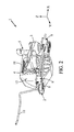
figures 1 and2 are perspective views, viewed respectively from above and from below, of an example of anti-vibration device according to one embodiment of the the invention, -
figure 3 is an exploded view in perspective of the anti-vibration device offigures 1 and2 , -
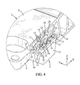
figure 4 is an enlarged perspective view showing one of the elastic clips of the anti-vibration device, -
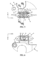
figures 5 and 6 are respectively top and bottom views of the clip offigure 3 , and -
figures 7 and 8 are section views of the clip, the sections being made accordng to lines VII-VII and VIII-VIII offigure 5 . - In the various figures, the same references designate identical or similar elements.
-
Figures 1 and2 represent an anti-vibration device 1 that is adapted to connect: - on the one hand, a first rigid element, for example the body of a vehicle (not shown), and
- on the other hand, a second rigid element, for example the engine of the vehicle (not shown).
- The anti-vibration device 1 includes at least first and
second strength members elastomer body 4. - In the example shown, the
first strength member 2, which is designed to be fixed to the vehicle body, is a plastic part molded in one piece by injection molding, whereas the second strength member, which is designed to be fixed to the vehicle engine, is usually a metal part, for instance a part molded or casted in light alloy. - The upper face of the first strength member may also bear a
limiter 5 fixed thereon. For instance, the limiter may have a substantially inverted U shape and may thus include: - a substantially
horizontal bridge portion 11 covering theelastomer body 4 and thesecond strength member 3; - two substantially
vertical legs 12 on both sides of thebridge portion 11; - and two
lugs 13 bearing on the upper face of theplatform 6 and being abale to be fixed thereon by screws (not shown) which also fix the first strength member to the vehicle body. - The first strength member includes at least one
clip 9, for instance twoclips 9 in the example shown, which are molded in plastic material as one single piece with thefirst strength member 2, and which are adapted to retain aconduit 10 thereon by snap-fitting. The conduit in question can be for instance a tube, a cable (e.g. electric cable, optic cable, mechanical transmission cable), or any other kind of conduit. - As shown for instance on
figure 3 , thefirst strength member 2 may comprise arigid platform 6 which is substantially horizontal in use (ie substantially parallel to a plane XY, where X and Y are two mutually perpendicular axes). On the upper face of thisplatform 6 are fixed theelastomer body 4 and thelimiter 5. Theplatform 6 may include two sbstantially parallellonger edges edge 8, thus not interfering with the fixation od theelastomer body 4 and limiter 5. - As shown in more details in
figures 4-8 , eachclip 9 may include: - a substantially rigid casing 14-16 extending laterally from said platform and defining at least one and preferably two upwardly
opening slots 22 adapted to receive saidconduit 10; - and at least one
elastic tab 20, preferably two mutually opposedtabs 20, protruding inwardly relative to saidslots 22 and adapted to retain saidconduit 10 by snap-fitting, said casing surrounding said elastic tab so as to protect it, thus avoiding saidelastic tab 20 to be broken during the assembling process or transport. - In the example shown, the casing includes:
- two substantially
parallel side walls 14 extending laterally from theplatform 6 in a substantially vertical plane YZ (where Z is a vertical axis) and each forming one of the upwardlyopen slots 22; - substantially parallel front and
back walls side walls 14 together and extend in a substantially vertical plane XZ, theback wall 16 being closer to theplatform 6 than thefront wall 15. - Each
elastic tab 20 joins the twoside walls 14 together and extends substantially parallel to said front andback walls back walls elastic tongues 20 during snap-fitting. - In the example shown, each said
elastic tab 20 includes acentral locking member 25 protruding inwardly relative to saidslots 22 for snap fitting with theconduit 10, and two elastically deformable portions each having a shape of an inverted U, each elastically deformable portion having: - a
first branch 21 extending upwardly from one of theside walls 14 up to an upper end (theslot 22 of eachside wall 14 is thus defined between the twobranches 21 extending therefrom); - a
second branch 24 extending upwardly from saidcentral locking member 25 up to an upper end; - and a
top portion 23 joining the upper ends of the first andsecond branches - The front and
back walls upper portion 17 forming the upper edged of said walls. Theupper portions 17 of the front andback walls upper guide members 19 protruding inwardly toward each other above the lockingmembers 25 of theelastic tongues 20 and adapted to guide theconduit 10 toward theslots 22 when theconduit 10 is inserterd in theclip 9. Similarly, theupper portions 17 of said front andback walls lateral guide members 18, thelateral guide members 18 of each pair protruding inwardly toward each other near theside walls 14 of the casing and being adapted to guide theconduit 10 toward theslots 22 when the conduit is inserterd in the clip. - The
clips 9 are adapted to be unmolded in one single movement when unmolding the first strength member, so that the molding of the clip with the platform implies no added complexity in the molding process and very low added cost compared to the molding of te platform alone.
Claims (10)
- Anti-vibration device including at least first and second strength members (2, 3) interconnected by an elastomer body (4), at least the first strength member (2) being made at least partially of molded plastic material, wherein the first strength member (2) further includes at least one clip (9) of molded plastic material, which is adapted to retain a conduit thereon by snap-fitting.
- Anti-vibration device according to claim 1, wherein the first strength member comprises a platform (6) on which the elastomer body is fixed, and the clip includes:- a substantially rigid casing (14-16) extending laterally from said platform (6) and defining at least one upwardly opening slot (22) adapted to receive said conduit;- and at least one elastic tab (20) protruding inwardly relative to said slot (22) and adapted to retain said conduit by snap-fitting, said casing (14-16) surrounding said elastic tab so as to protect said elastic tab.
- Anti-vibration device according to claim 2, wherein said casing (14-16) includes:- two substantially parallel side walls (14) extending laterally from the platform (6) each forming one upwardly open slot (22);- substantially parallel front and back walls (15, 16) which join the two side walls (14) together, the back wall (16) being closer to the platform (6) than the front wall (15); said side walls (14), front wall (15) and back wall (16) being substantially perpendicular to the platform (6) and surrounding said at least one elastic tab (20), the clip being adapted to be unmolded in one single movement.
- Anti-vibration device according to claim 3, wherein said at least one elastic tab (20) joins the two side walls (14) together and extends substantially parallel to said front and back walls (15, 16), one of said front and back walls being positionned for limiting deformation of said elastic tab.
- Anti-vibration device according to claim 3 or claim 4, wherein the clip includes two elastic tabs facing each other
- Anti-vibration device according to anyone of claims 3-5, wherein said elastic tab (20) includes a central locking member (25) protruding inwardly relative to said slots (22) and two elastically deformable portions each having a shape of an inverted U, each elastically deformable portion having:- a first branch (21) extending upwardly from one of the side walls (14) up to an upper end;- a second branch (24) extending upwardly from said central locking member up to an upper end;- and a top portion (23) joining the upper ends of the first and second branches together.
- Anti-vibration device according to anyone of claims 3-6, wherein said front and back walls (15, 16) each have an upper portion (17), the upper portions of said front and back walls including respectively two upper guide members (19) protruding inwardly toward each other and adapted to guide said conduit toward said slot (22) when the conduit is inserterd in the clip.
- Anti-vibration device according to anyone of claims 3-7, wherein said front and back walls (15, 16) each have an upper portion (17), the upper portions of said front and back walls including respectively two pairs of lateral guide members (19), the lateral guide members of each pair protruding inwardly toward each other near the side walls of the casing and being adapted to guide said conduit toward said slot when the conduit is inserterd in the clip.
- Anti-vibration device according to anyone of claims 1-8, wherein the first strength member includes two clips (9), the slots (22) of which are in mutual alignment from one clip to the other.
- Assembly including an anti-vibration device (1) according to anyone of claims 1-9 and a conduit (10) snap-fitted to the at least one clip (9) of the first strenth member (2).
Applications Claiming Priority (1)
| Application Number | Priority Date | Filing Date | Title |
|---|---|---|---|
| US13/334,939 US20130161886A1 (en) | 2011-12-22 | 2011-12-22 | Anti-Vibration Device and Assembly Including such Device |
Publications (1)
| Publication Number | Publication Date |
|---|---|
| EP2607740A2 true EP2607740A2 (en) | 2013-06-26 |
Family
ID=47294720
Family Applications (1)
| Application Number | Title | Priority Date | Filing Date |
|---|---|---|---|
| EP12195175.0A Withdrawn EP2607740A2 (en) | 2011-12-22 | 2012-11-30 | Anti-vibration device and assembly including such device |
Country Status (3)
| Country | Link |
|---|---|
| US (1) | US20130161886A1 (en) |
| EP (1) | EP2607740A2 (en) |
| CN (1) | CN103174794A (en) |
Citations (1)
| Publication number | Priority date | Publication date | Assignee | Title |
|---|---|---|---|---|
| US20100264570A1 (en) | 2007-05-24 | 2010-10-21 | Pascal Thierry | Anti-Vibration Device |
Family Cites Families (18)
| Publication number | Priority date | Publication date | Assignee | Title |
|---|---|---|---|---|
| US1398519A (en) * | 1921-03-14 | 1921-11-29 | Greene C Hosch | Hanger |
| US4601451A (en) * | 1982-11-16 | 1986-07-22 | Diamond Communication Products, Inc. | Dual amplifier tap bracket or the like |
| US4509710A (en) * | 1983-12-23 | 1985-04-09 | Amp Incorporated | Cable clamp |
| US4823752A (en) * | 1988-02-23 | 1989-04-25 | Brigg & Stratton Corporation | Engine speed control cable clamp |
| US4909218A (en) * | 1988-12-30 | 1990-03-20 | Briggs & Stratton Corporation | Engine speed control cable clamp assembly |
| JP2671795B2 (en) * | 1993-12-27 | 1997-10-29 | 日本電気株式会社 | Anti-vibration bracket |
| JP3471430B2 (en) * | 1994-07-18 | 2003-12-02 | 株式会社モルテン | clip |
| JPH10299829A (en) * | 1997-04-25 | 1998-11-13 | Alps Electric Co Ltd | Vibration isolating mechanism and disc driving device employing the vibration isolating mechanism |
| US6899305B2 (en) * | 1999-01-12 | 2005-05-31 | Andrew Corporation | Stackable transmission line hanger |
| FR2825128B1 (en) * | 2001-05-25 | 2003-08-15 | Hutchinson | ANTI-VIBRATION SUPPORT AND METHOD OF MANUFACTURING SUCH A SUPPORT |
| US8627552B2 (en) * | 2001-06-25 | 2014-01-14 | Termax Corporation | Multicontact adaptive fastener clip |
| JP2004242478A (en) * | 2003-02-10 | 2004-08-26 | Nippon Pop Rivets & Fasteners Ltd | Cable clamp |
| US20040182972A1 (en) * | 2003-03-19 | 2004-09-23 | Bakos Gregory J. | Electrical connector holder |
| US7735867B2 (en) * | 2005-04-07 | 2010-06-15 | Traxxas Lp | Double looped fuel line for a model vehicle |
| JP4443463B2 (en) * | 2005-04-28 | 2010-03-31 | 北川工業株式会社 | Clamp |
| JP4713455B2 (en) * | 2006-12-19 | 2011-06-29 | 株式会社パイオラックス | clip |
| WO2009022762A1 (en) * | 2007-08-16 | 2009-02-19 | Jeong Yel Park | Nipper |
| US8672303B2 (en) * | 2009-01-14 | 2014-03-18 | Honda Motor Co., Ltd. | Bush for isolating stabilizer from vibration |
-
2011
- 2011-12-22 US US13/334,939 patent/US20130161886A1/en not_active Abandoned
-
2012
- 2012-11-30 EP EP12195175.0A patent/EP2607740A2/en not_active Withdrawn
- 2012-12-11 CN CN2012105702266A patent/CN103174794A/en active Pending
Patent Citations (1)
| Publication number | Priority date | Publication date | Assignee | Title |
|---|---|---|---|---|
| US20100264570A1 (en) | 2007-05-24 | 2010-10-21 | Pascal Thierry | Anti-Vibration Device |
Also Published As
| Publication number | Publication date |
|---|---|
| US20130161886A1 (en) | 2013-06-27 |
| CN103174794A (en) | 2013-06-26 |
Similar Documents
| Publication | Publication Date | Title |
|---|---|---|
| JP6633824B2 (en) | connector | |
| US9458868B2 (en) | Plug-in coupling and method for the production thereof | |
| KR101810807B1 (en) | Holding frame for a plug connector | |
| CN110537298A (en) | Retaining frame for plug-in connector and assembly method thereof | |
| KR101495512B1 (en) | Reverse-Assemblying Preventing Clip for Fixing Cable | |
| US10196015B2 (en) | Wire housing protector | |
| KR102204446B1 (en) | Connector mounting unit | |
| CN105849846B (en) | Electromagnetic contactor | |
| CN105339684A (en) | Vertically movable clip connection system | |
| US12291101B2 (en) | Motor mount | |
| US11189995B2 (en) | Connection arrangement and line routing device | |
| KR20170000615U (en) | Hidden zipper slider assembly structure and sliding member thereof for use in increasing positioning effect | |
| US8449251B2 (en) | Fan module | |
| US8601650B2 (en) | Attachment structure of clip | |
| EP2607740A2 (en) | Anti-vibration device and assembly including such device | |
| EP2335972A1 (en) | Clip for holding a fastening elastic string | |
| US20150108287A1 (en) | Wire holder mounting structure and display device | |
| US20120128410A1 (en) | Clip | |
| US20150016785A1 (en) | Optical connector, male connector housing for optical connector, and female connector housing for optical connector | |
| US9547326B2 (en) | Mechanical assembly of the press-button type, and application to an electrical apparatus | |
| EP2916014A1 (en) | System for connecting components | |
| US20110201225A1 (en) | Electrical connector comprising a guiding protrusion or pocket with a flexible fastening member | |
| EP2960567B1 (en) | Reinforcement structure for structural body having fastening sections | |
| CN222509707U (en) | Buckle structure for BMS controller housing and BMS controller housing | |
| JP4676556B1 (en) | connector |
Legal Events
| Date | Code | Title | Description |
|---|---|---|---|
| AK | Designated contracting states |
Kind code of ref document: A2 Designated state(s): AL AT BE BG CH CY CZ DE DK EE ES FI FR GB GR HR HU IE IS IT LI LT LU LV MC MK MT NL NO PL PT RO RS SE SI SK SM TR |
|
| AX | Request for extension of the european patent |
Extension state: BA ME |
|
| PUAI | Public reference made under article 153(3) epc to a published international application that has entered the european phase |
Free format text: ORIGINAL CODE: 0009012 |
|
| STAA | Information on the status of an ep patent application or granted ep patent |
Free format text: STATUS: THE APPLICATION IS DEEMED TO BE WITHDRAWN |
|
| 18D | Application deemed to be withdrawn |
Effective date: 20160601 |