EP2607655A2 - Intake liner for a gas turbine engine - Google Patents
Intake liner for a gas turbine engine Download PDFInfo
- Publication number
- EP2607655A2 EP2607655A2 EP20120196982 EP12196982A EP2607655A2 EP 2607655 A2 EP2607655 A2 EP 2607655A2 EP 20120196982 EP20120196982 EP 20120196982 EP 12196982 A EP12196982 A EP 12196982A EP 2607655 A2 EP2607655 A2 EP 2607655A2
- Authority
- EP
- European Patent Office
- Prior art keywords
- holes
- intake
- turbine engine
- gas turbine
- compressed gas
- Prior art date
- Legal status (The legal status is an assumption and is not a legal conclusion. Google has not performed a legal analysis and makes no representation as to the accuracy of the status listed.)
- Withdrawn
Links
- 238000000926 separation method Methods 0.000 claims abstract description 43
- 230000015572 biosynthetic process Effects 0.000 claims abstract description 19
- 230000035939 shock Effects 0.000 claims description 23
- 230000002265 prevention Effects 0.000 claims description 5
- 230000001141 propulsive effect Effects 0.000 abstract description 4
- 238000005755 formation reaction Methods 0.000 description 16
- 239000012530 fluid Substances 0.000 description 5
- 239000000463 material Substances 0.000 description 5
- 125000006850 spacer group Chemical group 0.000 description 5
- 230000007613 environmental effect Effects 0.000 description 4
- 230000001629 suppression Effects 0.000 description 4
- 238000002485 combustion reaction Methods 0.000 description 3
- 238000013461 design Methods 0.000 description 3
- 230000002411 adverse Effects 0.000 description 2
- 230000009286 beneficial effect Effects 0.000 description 2
- 230000001413 cellular effect Effects 0.000 description 2
- 230000001419 dependent effect Effects 0.000 description 2
- 238000010438 heat treatment Methods 0.000 description 2
- 238000000034 method Methods 0.000 description 2
- 230000035515 penetration Effects 0.000 description 2
- 230000009467 reduction Effects 0.000 description 2
- 230000002238 attenuated effect Effects 0.000 description 1
- 238000007664 blowing Methods 0.000 description 1
- 238000004891 communication Methods 0.000 description 1
- 150000001875 compounds Chemical class 0.000 description 1
- 230000006835 compression Effects 0.000 description 1
- 238000007906 compression Methods 0.000 description 1
- 230000001627 detrimental effect Effects 0.000 description 1
- 239000000446 fuel Substances 0.000 description 1
- 238000002347 injection Methods 0.000 description 1
- 239000007924 injection Substances 0.000 description 1
- 230000000116 mitigating effect Effects 0.000 description 1
- 239000000203 mixture Substances 0.000 description 1
- 230000003071 parasitic effect Effects 0.000 description 1
- 238000012545 processing Methods 0.000 description 1
- 230000007480 spreading Effects 0.000 description 1
- 230000008719 thickening Effects 0.000 description 1
- 238000012546 transfer Methods 0.000 description 1
- 238000011282 treatment Methods 0.000 description 1
- 239000013585 weight reducing agent Substances 0.000 description 1
Images



Classifications
-
- F—MECHANICAL ENGINEERING; LIGHTING; HEATING; WEAPONS; BLASTING
- F02—COMBUSTION ENGINES; HOT-GAS OR COMBUSTION-PRODUCT ENGINE PLANTS
- F02C—GAS-TURBINE PLANTS; AIR INTAKES FOR JET-PROPULSION PLANTS; CONTROLLING FUEL SUPPLY IN AIR-BREATHING JET-PROPULSION PLANTS
- F02C7/00—Features, components parts, details or accessories, not provided for in, or of interest apart form groups F02C1/00 - F02C6/00; Air intakes for jet-propulsion plants
- F02C7/04—Air intakes for gas-turbine plants or jet-propulsion plants
-
- B—PERFORMING OPERATIONS; TRANSPORTING
- B64—AIRCRAFT; AVIATION; COSMONAUTICS
- B64C—AEROPLANES; HELICOPTERS
- B64C21/00—Influencing air flow over aircraft surfaces by affecting boundary layer flow
- B64C21/02—Influencing air flow over aircraft surfaces by affecting boundary layer flow by use of slot, ducts, porous areas or the like
- B64C21/04—Influencing air flow over aircraft surfaces by affecting boundary layer flow by use of slot, ducts, porous areas or the like for blowing
-
- B—PERFORMING OPERATIONS; TRANSPORTING
- B64—AIRCRAFT; AVIATION; COSMONAUTICS
- B64D—EQUIPMENT FOR FITTING IN OR TO AIRCRAFT; FLIGHT SUITS; PARACHUTES; ARRANGEMENT OR MOUNTING OF POWER PLANTS OR PROPULSION TRANSMISSIONS IN AIRCRAFT
- B64D33/00—Arrangement in aircraft of power plant parts or auxiliaries not otherwise provided for
- B64D33/02—Arrangement in aircraft of power plant parts or auxiliaries not otherwise provided for of combustion air intakes
-
- F—MECHANICAL ENGINEERING; LIGHTING; HEATING; WEAPONS; BLASTING
- F02—COMBUSTION ENGINES; HOT-GAS OR COMBUSTION-PRODUCT ENGINE PLANTS
- F02C—GAS-TURBINE PLANTS; AIR INTAKES FOR JET-PROPULSION PLANTS; CONTROLLING FUEL SUPPLY IN AIR-BREATHING JET-PROPULSION PLANTS
- F02C3/00—Gas-turbine plants characterised by the use of combustion products as the working fluid
- F02C3/32—Inducing air flow by fluid jet, e.g. ejector action
-
- F—MECHANICAL ENGINEERING; LIGHTING; HEATING; WEAPONS; BLASTING
- F02—COMBUSTION ENGINES; HOT-GAS OR COMBUSTION-PRODUCT ENGINE PLANTS
- F02C—GAS-TURBINE PLANTS; AIR INTAKES FOR JET-PROPULSION PLANTS; CONTROLLING FUEL SUPPLY IN AIR-BREATHING JET-PROPULSION PLANTS
- F02C7/00—Features, components parts, details or accessories, not provided for in, or of interest apart form groups F02C1/00 - F02C6/00; Air intakes for jet-propulsion plants
- F02C7/04—Air intakes for gas-turbine plants or jet-propulsion plants
- F02C7/045—Air intakes for gas-turbine plants or jet-propulsion plants having provisions for noise suppression
-
- F—MECHANICAL ENGINEERING; LIGHTING; HEATING; WEAPONS; BLASTING
- F02—COMBUSTION ENGINES; HOT-GAS OR COMBUSTION-PRODUCT ENGINE PLANTS
- F02C—GAS-TURBINE PLANTS; AIR INTAKES FOR JET-PROPULSION PLANTS; CONTROLLING FUEL SUPPLY IN AIR-BREATHING JET-PROPULSION PLANTS
- F02C7/00—Features, components parts, details or accessories, not provided for in, or of interest apart form groups F02C1/00 - F02C6/00; Air intakes for jet-propulsion plants
- F02C7/04—Air intakes for gas-turbine plants or jet-propulsion plants
- F02C7/047—Heating to prevent icing
-
- F—MECHANICAL ENGINEERING; LIGHTING; HEATING; WEAPONS; BLASTING
- F02—COMBUSTION ENGINES; HOT-GAS OR COMBUSTION-PRODUCT ENGINE PLANTS
- F02C—GAS-TURBINE PLANTS; AIR INTAKES FOR JET-PROPULSION PLANTS; CONTROLLING FUEL SUPPLY IN AIR-BREATHING JET-PROPULSION PLANTS
- F02C7/00—Features, components parts, details or accessories, not provided for in, or of interest apart form groups F02C1/00 - F02C6/00; Air intakes for jet-propulsion plants
- F02C7/04—Air intakes for gas-turbine plants or jet-propulsion plants
- F02C7/057—Control or regulation
-
- B—PERFORMING OPERATIONS; TRANSPORTING
- B64—AIRCRAFT; AVIATION; COSMONAUTICS
- B64C—AEROPLANES; HELICOPTERS
- B64C2230/00—Boundary layer controls
- B64C2230/14—Boundary layer controls achieving noise reductions
-
- B—PERFORMING OPERATIONS; TRANSPORTING
- B64—AIRCRAFT; AVIATION; COSMONAUTICS
- B64D—EQUIPMENT FOR FITTING IN OR TO AIRCRAFT; FLIGHT SUITS; PARACHUTES; ARRANGEMENT OR MOUNTING OF POWER PLANTS OR PROPULSION TRANSMISSIONS IN AIRCRAFT
- B64D33/00—Arrangement in aircraft of power plant parts or auxiliaries not otherwise provided for
- B64D33/02—Arrangement in aircraft of power plant parts or auxiliaries not otherwise provided for of combustion air intakes
- B64D2033/0206—Arrangement in aircraft of power plant parts or auxiliaries not otherwise provided for of combustion air intakes comprising noise reduction means, e.g. acoustic liners
-
- B—PERFORMING OPERATIONS; TRANSPORTING
- B64—AIRCRAFT; AVIATION; COSMONAUTICS
- B64D—EQUIPMENT FOR FITTING IN OR TO AIRCRAFT; FLIGHT SUITS; PARACHUTES; ARRANGEMENT OR MOUNTING OF POWER PLANTS OR PROPULSION TRANSMISSIONS IN AIRCRAFT
- B64D33/00—Arrangement in aircraft of power plant parts or auxiliaries not otherwise provided for
- B64D33/02—Arrangement in aircraft of power plant parts or auxiliaries not otherwise provided for of combustion air intakes
- B64D2033/0226—Arrangement in aircraft of power plant parts or auxiliaries not otherwise provided for of combustion air intakes comprising boundary layer control means
-
- B—PERFORMING OPERATIONS; TRANSPORTING
- B64—AIRCRAFT; AVIATION; COSMONAUTICS
- B64D—EQUIPMENT FOR FITTING IN OR TO AIRCRAFT; FLIGHT SUITS; PARACHUTES; ARRANGEMENT OR MOUNTING OF POWER PLANTS OR PROPULSION TRANSMISSIONS IN AIRCRAFT
- B64D33/00—Arrangement in aircraft of power plant parts or auxiliaries not otherwise provided for
- B64D33/02—Arrangement in aircraft of power plant parts or auxiliaries not otherwise provided for of combustion air intakes
- B64D2033/0233—Arrangement in aircraft of power plant parts or auxiliaries not otherwise provided for of combustion air intakes comprising de-icing means
-
- F—MECHANICAL ENGINEERING; LIGHTING; HEATING; WEAPONS; BLASTING
- F05—INDEXING SCHEMES RELATING TO ENGINES OR PUMPS IN VARIOUS SUBCLASSES OF CLASSES F01-F04
- F05D—INDEXING SCHEME FOR ASPECTS RELATING TO NON-POSITIVE-DISPLACEMENT MACHINES OR ENGINES, GAS-TURBINES OR JET-PROPULSION PLANTS
- F05D2260/00—Function
- F05D2260/60—Fluid transfer
- F05D2260/601—Fluid transfer using an ejector or a jet pump
-
- F—MECHANICAL ENGINEERING; LIGHTING; HEATING; WEAPONS; BLASTING
- F05—INDEXING SCHEMES RELATING TO ENGINES OR PUMPS IN VARIOUS SUBCLASSES OF CLASSES F01-F04
- F05D—INDEXING SCHEME FOR ASPECTS RELATING TO NON-POSITIVE-DISPLACEMENT MACHINES OR ENGINES, GAS-TURBINES OR JET-PROPULSION PLANTS
- F05D2260/00—Function
- F05D2260/96—Preventing, counteracting or reducing vibration or noise
-
- F—MECHANICAL ENGINEERING; LIGHTING; HEATING; WEAPONS; BLASTING
- F05—INDEXING SCHEMES RELATING TO ENGINES OR PUMPS IN VARIOUS SUBCLASSES OF CLASSES F01-F04
- F05D—INDEXING SCHEME FOR ASPECTS RELATING TO NON-POSITIVE-DISPLACEMENT MACHINES OR ENGINES, GAS-TURBINES OR JET-PROPULSION PLANTS
- F05D2260/00—Function
- F05D2260/96—Preventing, counteracting or reducing vibration or noise
- F05D2260/962—Preventing, counteracting or reducing vibration or noise by means of "anti-noise"
-
- F—MECHANICAL ENGINEERING; LIGHTING; HEATING; WEAPONS; BLASTING
- F05—INDEXING SCHEMES RELATING TO ENGINES OR PUMPS IN VARIOUS SUBCLASSES OF CLASSES F01-F04
- F05D—INDEXING SCHEME FOR ASPECTS RELATING TO NON-POSITIVE-DISPLACEMENT MACHINES OR ENGINES, GAS-TURBINES OR JET-PROPULSION PLANTS
- F05D2260/00—Function
- F05D2260/96—Preventing, counteracting or reducing vibration or noise
- F05D2260/963—Preventing, counteracting or reducing vibration or noise by Helmholtz resonators
-
- F—MECHANICAL ENGINEERING; LIGHTING; HEATING; WEAPONS; BLASTING
- F05—INDEXING SCHEMES RELATING TO ENGINES OR PUMPS IN VARIOUS SUBCLASSES OF CLASSES F01-F04
- F05D—INDEXING SCHEME FOR ASPECTS RELATING TO NON-POSITIVE-DISPLACEMENT MACHINES OR ENGINES, GAS-TURBINES OR JET-PROPULSION PLANTS
- F05D2260/00—Function
- F05D2260/96—Preventing, counteracting or reducing vibration or noise
- F05D2260/964—Preventing, counteracting or reducing vibration or noise counteracting thermoacoustic noise
-
- Y—GENERAL TAGGING OF NEW TECHNOLOGICAL DEVELOPMENTS; GENERAL TAGGING OF CROSS-SECTIONAL TECHNOLOGIES SPANNING OVER SEVERAL SECTIONS OF THE IPC; TECHNICAL SUBJECTS COVERED BY FORMER USPC CROSS-REFERENCE ART COLLECTIONS [XRACs] AND DIGESTS
- Y02—TECHNOLOGIES OR APPLICATIONS FOR MITIGATION OR ADAPTATION AGAINST CLIMATE CHANGE
- Y02T—CLIMATE CHANGE MITIGATION TECHNOLOGIES RELATED TO TRANSPORTATION
- Y02T50/00—Aeronautics or air transport
- Y02T50/10—Drag reduction
-
- Y—GENERAL TAGGING OF NEW TECHNOLOGICAL DEVELOPMENTS; GENERAL TAGGING OF CROSS-SECTIONAL TECHNOLOGIES SPANNING OVER SEVERAL SECTIONS OF THE IPC; TECHNICAL SUBJECTS COVERED BY FORMER USPC CROSS-REFERENCE ART COLLECTIONS [XRACs] AND DIGESTS
- Y10—TECHNICAL SUBJECTS COVERED BY FORMER USPC
- Y10T—TECHNICAL SUBJECTS COVERED BY FORMER US CLASSIFICATION
- Y10T137/00—Fluid handling
- Y10T137/0536—Highspeed fluid intake means [e.g., jet engine intake]
- Y10T137/0645—With condition responsive control means
Definitions
- the present invention relates to intakes and intake linings and more particularly to intakes and intake linings for a nacelle of a gas turbine engine.
- the purpose of the intake of civil turbofan gas turbine engines is to ensure that, under all operating conditions, the engine is supplied with the correct quantity of air and that the air has sufficient flow uniformity to allow efficient and stable operation of the engine.
- the intake design is integrated into the engine nacelle to obtain the lowest level of drag at the operating design point, typically cruise, for maximum efficiency.
- an optimum intake configuration is a short, near circular, pitot-type intake. This design is highly efficient for subsonic operation, as low levels of pressure loss are achieved under most and possibly all operating conditions.
- a pitot intake consists of two geometric regions, a lip and a throat. Downstream of the throat the airflow passes into a diffuser where the flow area is increased up to a fan entry plane.
- the diffuser acts as a settling length to improve the uniformity of the airflow entering the fan.
- the lip is a forward section and similar in section to an aerofoil and is shaped to guide the airflow into the engine under all operating conditions; the lip is also optimised to prevent flow separation under cross-wind and incidence operation. If flow separation occurs, this produces significant asymmetry in the total pressure within the intake increasing fan blade stresses and in severe cases engine surge.
- the internal surface of the lip is heated, usually with hot air, to minimise or ensure that there is no ice accretion, which could otherwise be shed and damage the engine.
- Other heating arrangements include electrical heating pads.
- the diffuser and throat regions of the intake are often lined with sound-absorbing acoustic panels to reduce noise from the fan and other turbomachinery of the engine.
- a gas turbine engine having a rotational axis, an intake and a compressed gas source; the intake is arranged about the rotational axis and includes a lining having a facing which defines an inlet surface and an array of holes; the array of holes comprises at least a first set of holes and a second set of holes, the holes of the first set of holes are angled ⁇ relative to a radial line with respect to the rotational axis and the holes of the second set of holes are angled ⁇ relative to the radial line; the angles ⁇ and ⁇ are different; the second set of holes is connected to the compressed gas source.
- the angle ⁇ may be between 0° and 15°.
- the angle ⁇ may be approximately 0°.
- the angle ⁇ may be between 15° and 75°.
- the angle ⁇ may be between 35° and 55°.
- the angle ⁇ may be approximately 45°.
- the first set of holes may be arranged to attenuate acoustic pressure waves and the second set of holes may be arranged to prevent icing and/or the formation of shock waves and/or boundary layer separation.
- the second set of holes may comprise holes that converge between their inlet and outlet.
- the second set of holes may comprise holes that diverge between their inlet and outlet
- the second set of holes may comprise holes that converge and diverge in mutually perpendicular directions between their inlet and outlet.
- the outlet may be a slot.
- the second set of holes may comprise holes having discrete inlets and a common outlet.
- the second set of holes may be supplied with a compressed gas.
- the second set of holes may be supplied with a compressed gas only during conditions where anti-icing and/or prevention of the formation of shock waves and/or boundary layer separation may occur.
- a gas turbine engine comprising an intake defining an inlet surface, a compressed gas source and an active flow control arrangement;
- the intake includes a lining having a facing which defines an inlet surface and an array of holes;
- the array of holes comprises at least a first set of holes and a second set of holes, the holes of the first set of holes are angled ⁇ relative to a radial line and the holes of the second set of holes are angled ⁇ relative to the radial line;
- the active flow control arrangement comprising a compressed gas supply pipe, a valve arrangement, a controller, a compressed gas distribution pipe;
- the supply pipe fluidly connects between the compressed gas source and the valve arrangement and the distribution pipe fluidly connects between the valve arrangement and intake surface for supply of compressed gas thereto;
- the active flow control arrangement is operable to supply compressed gas to the intake surface to prevent separation of a main air flow (9) passing through the intake from the inlet surface.
- a ducted fan gas turbine engine generally indicated at 10 has a principal and rotational axis X-X.
- the engine 10 comprises, in axial flow series, an air intake 11, a propulsive fan 12, an intermediate pressure compressor 13, a high-pressure compressor 14, combustion equipment 15, a high-pressure turbine 16, and intermediate pressure turbine 17, a low-pressure turbine 18 and a core engine exhaust nozzle 19.
- a nacelle 21 generally surrounds the engine 10 and defines the intake 12, a bypass duct 22 and a bypass exhaust nozzle 23.
- the gas turbine engine 10 works in a conventional manner so that a main air flow 9 entering the intake 11 is accelerated by the fan 12 to produce two air flows: a first air flow A into the intermediate pressure compressor 14 and a second air flow B which passes through the bypass duct 22 to provide propulsive thrust.
- the intermediate pressure compressor 13 compresses the air flow A directed into it before delivering that air to the high pressure compressor 14 where further compression takes place.
- the compressed air exhausted from the high-pressure compressor 14 is directed into the combustion equipment 15 where it is mixed with fuel and the mixture combusted.
- the resultant hot combustion products then expand through, and thereby drive the high, intermediate and low-pressure turbines 16, 17, 18 before being exhausted through the nozzle 19 to provide additional propulsive thrust.
- the high, intermediate and low-pressure turbines 16, 17, 18 respectively drive the high and intermediate pressure compressors 14, 13 and the fan 12 by suitable interconnecting shafts.
- the intake is a pitot-style intake consisting of the geometric regions, a lip 24, a throat 25 and a diffuser 26.
- the lip 24 is a forward section and guides air into the engine under all operating conditions; the geometric shape of the lip is also optimised to minimise flow separation under cross-wind and incidence operation. If flow separation occurs, this produces significant asymmetry in the total pressure within the intake increasing fan blade stresses and in severe cases engine surge.
- the intake contracts to a minimum area sized for the engine flow requirements and is known as the throat 25. Downstream of the throat the main air flow 9 passes into the diffuser 26 where the flow area is increased before a fan entry plane 27.
- the diffuser acts as a settling length to improve the uniformity of the airflow entering the fan 12.
- Separation of air entering the intake 11 and a surface 28 of the intake can occur as a result of adverse air flow conditions such as cross flows and high incidence conditions during operation of the gas turbine engine and which can reduce engine efficiency. Separation of air from the surface 28 can cause shock waves and it is therefore an object to suppress any possible separation. These shock wave separations in the flow are generally caused by cross wind and high incidence conditions to the intake causing boundary separation.
- An active flow control arrangement 30 is provided to blow or present a control gas flow to specific regions of the intake 11 to obviate or alleviate separation and/or shock waves and/or boundary layer separation.
- the active flow control arrangement 30 locally re-energises the main air flow 9 into the intake 11 by injecting or presenting a control gas flow in the main airflow or over the surface 28 and preferably into a boundary layer adjacent the intake surface.
- the active flow control arrangement is capable of mitigating adverse pressure gradients within the intake and particularly adjacent the surface 28.
- shockwaves on an intake surface is dependent upon one or many operational and environmental conditions. For a cross wind situation shockwaves are generally located near to a leading edge of the intake lip, but for high incidence situations shockwaves will be closer to the inlet throat. Thus by selectively applying localised flow control gas through the intake surface it is possible to minimise separations around part or all of the intake thereby minimising the amount of control airflow gas required.
- the active flow control arrangement 30 can be incorporated or act as part of an acoustic liner system giving additional noise attenuation benefits and duplicity of operation so minimising weight and other complications compared to providing separate linings for avoiding flow separation. Furthermore, the active flow control arrangement 30 may be utilised in de-icing functions providing a third function.
- the active flow control arrangement 30 comprises a system of pipework 31, 33 connecting between a control gas source(s) (12, 13, 14) and a chamber 35 defined in the intake 11.
- a valve arrangement 32 is operable via an electronic unit 34 which may be separate or part of an engine electronic control (EEC).
- EEC engine electronic control
- the valve arrangement 32 is operable to control the amount and delivery location of the control gas flow around part or all the intake.
- the control fluid source is shown as the intermediate compressor 13; however, other sources or combined sources include any compressor and/or turbine.
- EEC logic control and operation of the valve arrangement 32 can consider operational conditions such as relative air speed and direction, flight cycle, engine power condition and sensor readings. Local sensors can be positioned within the intake to monitor parameters, such as local pressures around the intake.
- FIG 2 is a schematic illustration of part of the intake 11 shown in Figure 1 and comprising a lining 40.
- the lining 40 comprises a surface liner 41, a spacer 43 and a backing 42.
- the surface liner 41 and the backing 42 are separated and spaced apart by the spacer 43 to provide structural strength.
- the spacer is a honeycomb material 43, but other cellular materials can be used.
- the surface liner 41 comprises an array of perforations 58 through its thickness to fluidly connect cells 49 of the cellular material with the main air flow 9 in the inlet 11 or other duct of a gas turbine engine.
- the combination between the perforations and cells absorb acoustic energy as is well known in the art. Double layered acoustic liners may also be used herein.
- the pipework 31, 33 connects to a distribution pipe 38, sometimes known as a piccolo pipe, for distribution of fluid around the chamber 35.
- the chamber is annular although it may comprise circumferential segments.
- the distribution pipe 38 is annular and in this case is housed within the chamber 35.
- the distribution pipe 38 may also be circumferentially segmented and/or housed external to the chamber 35.
- the surface liner 41 defines bespoke boundary-layer apertures 58C although they may be part of the array of perforations 58.
- the backing 42 defines inlet apertures 59 that allow fluid communication between the chamber 35 and the intake surface 28. Pressurised gas, control fluid flow 47, enters the chamber 35 and flows through the apertures 59, the cells 49 and exits through the surface liner 41.
- the boundary-layer apertures 58 are positioned at specific locations in order to inject the control fluid flow 47a, 47b at those specific regions of the lining 40.
- the active flow control arrangement 30 locally re-energises the boundary layer of the main air flow, in order to prevent the main air flow from separating from the surface 28 and particularly adjacent a shock wave 48, 50.
- the location and occurrence of shock waves adjacent the intake surface 28 is dependent on the operating condition of the engine, aircraft and environmental conditions.
- shock waves, indicated at 48 usually occur near a leading edge 52 of the intake lip 24.
- the shock waves, indicated at 50 usually occur near to the intake throat 25.
- the lining structure also operates as an acoustic lining, particularly in the lip region of the intake.
- Figure 3 is another schematic and enlarged section of part of an intake of the nacelle of Figure 1 .
- the intake 11 comprises the lip region 24, the throat region 25 and further downstream a diffuser region 26.
- the active flow control arrangement 30 further comprises ducting 50 to supply the compressed gas to the intake surface in the lip region 24, the throat region 25 and the diffuser region 26. It is within these regions that shock waves or main gas flow 9 separation may occur.
- the pipework 31, 33 connects to the distribution pipe 38 which then connects to a distribution network 50.
- the distribution network 50 comprises ducting having generally axial conduits 52 connecting between generally circumferential conduits 54A, 54B.
- the circumferential conduits 54A and 54B feed compressed gas to the lining 40 and then through the surface liner 41 and over the surface to re-energise the boundary layer preventing main flow separation and avoiding harmful shock waves from forming.
- Additional circumferential conduits 54 are shown in dashed lines to feed compressed gas to further areas where separation of the main gas flow from the surface 28 may occur.
- Figure 4 shows a distribution network 50 having conduit 52 connecting between the distribution pipe 38 and two circumferential conduits 54A and 54B.
- the circumferential conduits 54 feed compressed gas to the lining 40 in two axial positions, in this case to the lip and throat regions 24R and 25R respectively. Further circumferential conduits can be fed via axial conduit 52 or additional axial conduits, thereby other or additional locations of the surface 28 can be fed control gas 47.
- Figure 5 shows another distribution network 50 having axial conduits 52A and 52B connecting between the distribution pipe 38 and each of two circumferential conduits 54A and 54B respectively.
- controllable valves 56A and 56B are provided on the axial conduits 52A and 52B.
- the valves 56A and 56B are operable to allow control gas 47 to either one or both or more circumferential conduits 54A and 54B.
- the valves 56A and 56B may be provided on the junction of the distribution pipe 38 and axial conduits or circumferential conduits 54A and 54B and axial conduits 52A and 52B.
- FIG 6 is a schematic illustration of part of the active control flow arrangement. Shown are two supply pipes 31 a and 31 b coming from two different sources of compressed gas.
- the two supply pipes 31 a and 31 b connect to the valve arrangement 30 and further pipes 33a, 33b, 33c and 33d take compressed gas 47 to four zones or regions R1, R2, R3 and R4 around the circumference of the intake 11.
- the circumferential regions R1, R2, R3 and R4 comprise a lower region (R4), side regions (R1, R3) and an upper region (R2).
- the valve arrangement 30 is operable via controller 34 to select either one of the two (or more) compressed gas supplies or both simultaneously.
- the valve arrangement 30 is operable via controller 34 to select which pipe or pipes 33a, 33b, 33c and 33d takes compressed gas 47 to which of the four (or more) zones or regions R1, R2, R3 and R4.
- the two gas supplies are from two sources of different pressures and thus the pressure of the gas can be delivered in any desired quantity or temperature to any part of the intake surface 28.
- the two or more sources of compressed gas can be from different stages of the same compressor and/or different compressor including the intermediate and high pressure compressors as well as the low pressure compressor or fan.
- the array of perforations or holes 58 comprises at least a first set of holes 58A and a second set of holes 58B.
- the first set of holes 58A are arranged to primarily to attenuate acoustic pressure waves travelling through the intake 11.
- the second set of holes 58B are arranged to feed or inject relatively warmer/hotter compressed gas 47 adjacent the facing sheet 41 to prevent or remove ice.
- the second set of holes 58B can also be used to prevent or reduce the formation of shock waves and / or main gas flow 9 separation from the surface 28.
- the first set of holes 58A can be referred to as 'acoustic holes' and the second set of holes 58B can be referred to as 'gas injection holes'; however in the embodiments below each type of hole may have some of the benefits of the other.
- the first set of holes 58A and the second set of holes 58B have respective centre-lines 62A, 62B and are distinguished from one another by a difference in their angles relatives to a radial line 60.
- the radial line 60 is with respect to the main engine rotational axis X-X. Where the intake 11 is asymmetrical and/or drooped the radial line 60 may be with respect a centre of area line through the intake.
- the holes of first set of holes 58A are angled ⁇ relative to the radial line and the holes of the second set of holes are angled ⁇ relative to the radial line; the angles ⁇ and ⁇ are different.
- the angle ⁇ may be between 0° and 15° from the radial line.
- the angle ⁇ may be rearwardly as shown in Figure 7 , forwardly and/or circumferentially with respect to the engine and may be a compound angle being circumferentially inclined and rearwardly or forwardly inclined.
- the holes of the second set of holes 58B have respective centre-lines 62B and define the angle ⁇ to the radial line 60. These holes are angled and arranged to supply relatively warm gas adjacent the surface 28 to prevent ice accretion or remove ice already formed.
- the angle ⁇ is approximately 45°; however, ⁇ may be between 35° and 55° although the benefits of these holes can be achieved with an angle ⁇ between 15° and 75°.
- each of the first set of holes 58A and the second set of holes 58B has a primary purpose each may also partially provide some of the benefits of the other.
- the first set of holes 58A is supplied with compressed gas flow 47 which enters the cell(s) 49 through backing sheet 42 via chamber 35. Thus the gas 47 can pass through the holes 58A to also prevent ice accretion or remove ice from the surface 28.
- the second set of holes 58B may also attenuate acoustic pressure waves present in the intake. Although gas flow 47 is passing out of the facing sheet 41 the pressure wave can still passes through the hole 58B to the cell 49 thereby being attenuate. Although the angle of hole 58B is not ideal for attenuation, noise is still attenuated.
- the first set of holes 58A and / or the second set of holes 58B may be used to supply the gas flow to the surface or boundary layer to prevent the formation of shock waves or prevent the formation of separation of the main gas flow from the surface 28.
- the combination of the differently angled holes 58A, 58B can be particularly useful depending aircraft, engine and environmental conditions and the particular requirement for suppressing shock waves and/or flow separation.
- the angle of the holes 58A enables the compressed gas flow 47 to penetrate further into the main gas flow 9, whereas the holes 58B enables the compressed gas flow 47 to be directed more closely to the surface.
- the combination of normal and inclined holes gives a greater range of quantity and/or height above the surface 28 that the compressed gas flow 47 can be injected.
- the holes 58A are not supplied with the compressed gas source 47.
- the hole(s) 58A fluidly connects a cell 49A with the intake 11 and main gas flow passing 9.
- Another cell 49B is associated with the holes 58B and has a hole 59 through the backing sheet 42 to allow compressed gas flow 47 into the cell and exit through the hole 58B in order for anti-icing use and/or shock wave suppression.
- Figures 9 and 10 show sections through a part of the facing sheet 41 and plan views of the radially inward surface 28 over which main gas flow 9 passes. These figures show some alternative configurations of the holes 58A and 58B to further improve on the functioning of the intake lining 40. These improvements relate to acoustic attenuation, suppression of main airflow separation from the surface, prevention of shock waves and anti-icing.
- Each hole configuration may be used in conjunction with any other or others in the array of holes. These holes may be inclined as hereinbefore described, in any direction or normal to the surface 28.
- the axes X, Y, Z relate to the axial (engine rotational axis XX), the circumferential and radial directions respectively.
- the cross-sectional flow area of hole 64B is divergent between the facing's radially outer surface 66 and radially inner surface 68, 28. This will decelerate the flow allowing the compressed gas to remain near to the surface 66, 28.
- the divergence is in the direction of flow of compressed gas flow 47.
- the holes 64A, 64B and 64C are generally circular in cross-section and therefore where the hole is angled an elliptical inlet or outlet is formed on the surface as can be seen on the plan view.
- the elliptical outlet has its longer dimension in the direction of the main flow 9 direction.
- the cross-sectional flow area of hole 64C is convergent then divergent between the facing's radially outer surface 66 and radially inner surface 68, 28.
- there is an overall decrease in cross-sectional flow area between inlet and outlet however, it is possible to have the same inlet and outlet areas.
- This hole configuration allows a lower pressure drop for the flow through the hole and therefore allows a lower pressure supply or more compressed gas therethrough for a given pressure.
- This hole configuration also allows smooth entry and by accelerating the flow at the throat and diffusing it thereafter, the compressed gas may be fully diffused and can be accelerated to a high velocity allowing increased penetration into the boundary layer.
- hole 64E diverges either in one or both the XZ plane and the XY plane so that the air flow 47 reduces in velocity as it passes out of the outlet. Relative to a constant cross sectional area hole, slowing the flow down means that the airflow will adhere to the surface 28 better, whilst also spreading out more on the surface 28 and therefore can be more effective for the same amount of airflow 47 or operate with a reduced amount of airflow.
- hole 64F diverges in the XZ and XY planes to form an exit slot.
- a number of inlets may feed a single outlet slot. The airflow is slowed even further in this configuration as the outlet area can be greater than for hole 64E.
- Hole 64G converges in the XZ plane, but diverges in the XY plane so that its inlet and outlet areas are approximately equal, although the outlet's area can be more or less than the inlet area.
- the airflow 47 therefore enters and exits the hole 64G at approximately the same velocity.
- Hole 64H diverges only in the XY plane to form an outlet slot.
- the hole may also converge in the XZ plane.
- a number of inlets may feed the single outlet slot thereby forming a even distribution of compressed gas over the surface 28.
- each liner 40 to be optimized to attenuate acoustic pressure waves, prevent the formation of shock waves and / or main gas flow 9 separations from the surface 28 and prevent ice from forming and/or remove ice formations. All of these hole configurations may be utilised to inject the compressed gas 47 into or above the boundary layer of the main gas flow passing over surface 28.
- the hole configurations shown in figures 9 and 10 are primarily used for anti-icing and / or prevention of the formation of shock waves and / or boundary layer separation. These hole configurations also provide some acoustic attenuation, although when implemented in conjunction with the 'acoustic holes' 58A described with reference to Figures 7 and 8 , the overall liner 40 having an arrangement or combination of acoustic and gas flow holes.
- the active flow control arrangement 30 comprises at least one sensor 36a, 36b, 37a, 37b positioned within the intake.
- the sensor(s) is connected to the controller 34 which controls the valve arrangement 30 to control the supply of compressed gas to the intake surface 28.
- An array of sensors 36a, 36b, 37a, 37b comprises at least one sensor positioned relative to a number of axial and/or circumferential regions of the intake.
- the active flow control arrangement 30 is capable of supplying control gas 47 to any one or more regions of the intake surface 28 where a sensor senses a parameter that passes a predetermined threshold value indicative of the possibility of flow separation.
- the gas turbine engine 10 may be operated by determining a possible formation of separation of the main air flow from the surface 28 and blowing compressor gas onto the surface or into a boundary layer adjacent the surface to prevent separation of the main air flow from the surface 28.
- determining the axial and/or circumferential location(s) of a possible formation of separation of the main air flow from the surface (28) enables a minimum amount of control gas to be supplied. Off-taking compressed gas from a compressor can be detrimental its performance and therefore engine efficiency so minimising the amount of compressed gas used is beneficial.
- the active flow control arrangement 30 comprises sensors 36a, 36b, 37a, 37b located in the intake 11 and their sensed parameters input to the controller 34 it is possible to determine the possible formation of separation of the main air flow from the surface 28 comprises the steps of by sensing the parameter, in this case usually pressure, of the main gas flow over the surface 28. The sensed pressure is then compared to a predetermined or threshold value where it is known that a possible formation of separation of the main air flow from the surface 28 may occur.
- the parameter in this case usually pressure
- the controller 34 programmed with an algorithm, receives engine and / or flight operational parameters, and compares these to a predetermined or threshold value where it is known that a possible formation of separation of the main air flow from the surface 28 may occur.
- the engine operational parameter(s) comprise any one or more or combination of a flight cycle condition, airspeed, an angle of incidence, an engine throttle position, cross-wind strength and direction and weight on wheels.
- Pulsing may be either stopping and starting the flow or modulating the mass flow rate.
- Gas jets issuing from the holes not only inject a quantity of air into the main gas flow but the jet causes secondary vortices to form around it and which help stabilise and/or reduce the formation of separation. Where the jets are pulsed these secondary vortices persist downstream even after the jet is reduced or switched off.
- the active flow control arrangement and its method of use is intended to prevent possible formation of separation of the main air flow from the surface 28.
- the apparatus and method of using it with an acoustic liner the benefits of both can still be achieved.
- the perforations in the lining 41 can be used to supply the control gas to the surface and / or the boundary layer to re-energise the main flow.
- the active flow control arrangement can also be operated to supply heated compressed gas to the surface of the intake and thereby prevent ice build up.
- the control valves are operable to impart pulsing to the anti-ice gas flow through the (acoustic) liner to maximise shock suppression, while minimising the use of anti ice air.
- the sensors 36a, 36b, 37a, 37b also sense temperature and relay this parameter to the EEC for processing in consideration of operation of the active flow control arrangement as an anti-icing system.
- the EEC 34 may decide to preferentially use hotter gas from a different source either mixed or discreet for anti-icing measures rather than possibly cooler gas for preventing main air flow separation.
- an active flow control arrangement which is capable of delivering a control gas to the intake of a gas turbine engine to help prevent main air flow separation and/or ice accretion while attenuating noise from the turbomachinery.
- the active flow control arrangement provides minimal use of compressed gas and weight reduction, while greatly improving the quality of the main air flow into the engine for improved operational performance and reduction of damage.
- the compressed gas supply could be routed circumferentially and/or axially through the radially outer layer of spacer material.
- the distribution network 50 is formed by the radially outer layer of spacer material.
Landscapes
- Engineering & Computer Science (AREA)
- Chemical & Material Sciences (AREA)
- Combustion & Propulsion (AREA)
- Mechanical Engineering (AREA)
- General Engineering & Computer Science (AREA)
- Aviation & Aerospace Engineering (AREA)
- Structures Of Non-Positive Displacement Pumps (AREA)
- Supercharger (AREA)
Abstract
Description
- The present invention relates to intakes and intake linings and more particularly to intakes and intake linings for a nacelle of a gas turbine engine.
- The purpose of the intake of civil turbofan gas turbine engines is to ensure that, under all operating conditions, the engine is supplied with the correct quantity of air and that the air has sufficient flow uniformity to allow efficient and stable operation of the engine. The intake design is integrated into the engine nacelle to obtain the lowest level of drag at the operating design point, typically cruise, for maximum efficiency.
- For civil turbofans, an optimum intake configuration is a short, near circular, pitot-type intake. This design is highly efficient for subsonic operation, as low levels of pressure loss are achieved under most and possibly all operating conditions.
- A pitot intake consists of two geometric regions, a lip and a throat. Downstream of the throat the airflow passes into a diffuser where the flow area is increased up to a fan entry plane. The diffuser acts as a settling length to improve the uniformity of the airflow entering the fan. The lip is a forward section and similar in section to an aerofoil and is shaped to guide the airflow into the engine under all operating conditions; the lip is also optimised to prevent flow separation under cross-wind and incidence operation. If flow separation occurs, this produces significant asymmetry in the total pressure within the intake increasing fan blade stresses and in severe cases engine surge.
- The internal surface of the lip is heated, usually with hot air, to minimise or ensure that there is no ice accretion, which could otherwise be shed and damage the engine. Other heating arrangements include electrical heating pads.
- The diffuser and throat regions of the intake are often lined with sound-absorbing acoustic panels to reduce noise from the fan and other turbomachinery of the engine.
- It is desirable to provide an intake lining system which provides improved flow control to suppress shock waves and/or separation of the airflow from the intake's internal surface that can be caused by cross winds and high incident conditions.
- It is also desirable to provide anti-icing and acoustic treatments that minimise weight, complexity and parts count.
- In accordance with the present invention there is provided a gas turbine engine having a rotational axis, an intake and a compressed gas source; the intake is arranged about the rotational axis and includes a lining having a facing which defines an inlet surface and an array of holes; the array of holes comprises at least a first set of holes and a second set of holes, the holes of the first set of holes are angled α relative to a radial line with respect to the rotational axis and the holes of the second set of holes are angled β relative to the radial line; the angles α and β are different; the second set of holes is connected to the compressed gas source.
- The angle α may be between 0° and 15°.
- The angle α may be approximately 0°.
- The angle β may be between 15° and 75°.
- The angle β may be between 35° and 55°.
- The angle β may be approximately 45°.
- The first set of holes may be arranged to attenuate acoustic pressure waves and the second set of holes may be arranged to prevent icing and/or the formation of shock waves and/or boundary layer separation.
- The second set of holes may comprise holes that converge between their inlet and outlet.
- The second set of holes may comprise holes that diverge between their inlet and outlet
- The second set of holes may comprise holes that converge and diverge in mutually perpendicular directions between their inlet and outlet.
- The outlet may be a slot.
- The second set of holes may comprise holes having discrete inlets and a common outlet.
- The second set of holes may be supplied with a compressed gas.
- The second set of holes may be supplied with a compressed gas only during conditions where anti-icing and/or prevention of the formation of shock waves and/or boundary layer separation may occur.
- In another aspect of the present invention there is provided a gas turbine engine comprising an intake defining an inlet surface, a compressed gas source and an active flow control arrangement; the intake includes a lining having a facing which defines an inlet surface and an array of holes; the array of holes comprises at least a first set of holes and a second set of holes, the holes of the first set of holes are angled α relative to a radial line and the holes of the second set of holes are angled β relative to the radial line; the active flow control arrangement comprising a compressed gas supply pipe, a valve arrangement, a controller, a compressed gas distribution pipe; the supply pipe fluidly connects between the compressed gas source and the valve arrangement and the distribution pipe fluidly connects between the valve arrangement and intake surface for supply of compressed gas thereto; the active flow control arrangement is operable to supply compressed gas to the intake surface to prevent separation of a main air flow (9) passing through the intake from the inlet surface.
- Embodiments of aspects of the present invention will now be described by way of example only with reference to the accompanying drawings in which:
-
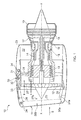
Figure 1 is a schematic section through a gas turbine engine and nacelle including an intake liner arrangement; -
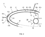
Figure 2 is a schematic and enlarged section of area C inFigure 1 ; -
Figure 3 is schematic and enlarged section of area D inFigure 2 ; -
Figure 4 is another schematic and enlarged section of area D inFigure 2 ; - Figures 5(a) and 5(b) are a schematic sectional view and a plan view of a facing sheet of the intake liner arrangement;
- Figures 6(a) and 6(b) are another schematic sectional view and another plan view of a facing sheet of the intake liner arrangement;
- With reference to
Figure 1 , a ducted fan gas turbine engine generally indicated at 10 has a principal and rotational axis X-X. Theengine 10 comprises, in axial flow series, anair intake 11, apropulsive fan 12, anintermediate pressure compressor 13, a high-pressure compressor 14,combustion equipment 15, a high-pressure turbine 16, andintermediate pressure turbine 17, a low-pressure turbine 18 and a coreengine exhaust nozzle 19. Anacelle 21 generally surrounds theengine 10 and defines theintake 12, a bypass duct 22 and abypass exhaust nozzle 23. - The
gas turbine engine 10 works in a conventional manner so that amain air flow 9 entering theintake 11 is accelerated by thefan 12 to produce two air flows: a first air flow A into theintermediate pressure compressor 14 and a second air flow B which passes through the bypass duct 22 to provide propulsive thrust. Theintermediate pressure compressor 13 compresses the air flow A directed into it before delivering that air to thehigh pressure compressor 14 where further compression takes place. - The compressed air exhausted from the high-
pressure compressor 14 is directed into thecombustion equipment 15 where it is mixed with fuel and the mixture combusted. The resultant hot combustion products then expand through, and thereby drive the high, intermediate and low-pressure turbines nozzle 19 to provide additional propulsive thrust. The high, intermediate and low-pressure turbines intermediate pressure compressors fan 12 by suitable interconnecting shafts. - The intake, generally shown at 11, is a pitot-style intake consisting of the geometric regions, a
lip 24, athroat 25 and adiffuser 26. Thelip 24 is a forward section and guides air into the engine under all operating conditions; the geometric shape of the lip is also optimised to minimise flow separation under cross-wind and incidence operation. If flow separation occurs, this produces significant asymmetry in the total pressure within the intake increasing fan blade stresses and in severe cases engine surge. - Downstream of the
lip 24 the intake contracts to a minimum area sized for the engine flow requirements and is known as thethroat 25. Downstream of the throat themain air flow 9 passes into thediffuser 26 where the flow area is increased before afan entry plane 27. The diffuser acts as a settling length to improve the uniformity of the airflow entering thefan 12. - Separation of air entering the
intake 11 and asurface 28 of the intake can occur as a result of adverse air flow conditions such as cross flows and high incidence conditions during operation of the gas turbine engine and which can reduce engine efficiency. Separation of air from thesurface 28 can cause shock waves and it is therefore an object to suppress any possible separation. These shock wave separations in the flow are generally caused by cross wind and high incidence conditions to the intake causing boundary separation. An activeflow control arrangement 30 is provided to blow or present a control gas flow to specific regions of theintake 11 to obviate or alleviate separation and/or shock waves and/or boundary layer separation. - The active
flow control arrangement 30 locally re-energises themain air flow 9 into theintake 11 by injecting or presenting a control gas flow in the main airflow or over thesurface 28 and preferably into a boundary layer adjacent the intake surface. By supplying a control flow and re-energising the boundary layer prevention or reduction of shock waves is possible. Indeed the active flow control arrangement is capable of mitigating adverse pressure gradients within the intake and particularly adjacent thesurface 28. - The location of shockwaves on an intake surface is dependent upon one or many operational and environmental conditions. For a cross wind situation shockwaves are generally located near to a leading edge of the intake lip, but for high incidence situations shockwaves will be closer to the inlet throat. Thus by selectively applying localised flow control gas through the intake surface it is possible to minimise separations around part or all of the intake thereby minimising the amount of control airflow gas required.
- As indicated generally the active
flow control arrangement 30 can be incorporated or act as part of an acoustic liner system giving additional noise attenuation benefits and duplicity of operation so minimising weight and other complications compared to providing separate linings for avoiding flow separation. Furthermore, the activeflow control arrangement 30 may be utilised in de-icing functions providing a third function. - As schematically shown in
Figure 1 , the activeflow control arrangement 30 comprises a system ofpipework chamber 35 defined in theintake 11. Avalve arrangement 32 is operable via anelectronic unit 34 which may be separate or part of an engine electronic control (EEC). Thevalve arrangement 32 is operable to control the amount and delivery location of the control gas flow around part or all the intake. The control fluid source is shown as theintermediate compressor 13; however, other sources or combined sources include any compressor and/or turbine. EEC logic control and operation of thevalve arrangement 32 can consider operational conditions such as relative air speed and direction, flight cycle, engine power condition and sensor readings. Local sensors can be positioned within the intake to monitor parameters, such as local pressures around the intake. -
Figure 2 is a schematic illustration of part of theintake 11 shown inFigure 1 and comprising alining 40. The lining 40 comprises asurface liner 41, aspacer 43 and abacking 42. Thesurface liner 41 and thebacking 42 are separated and spaced apart by thespacer 43 to provide structural strength. Usually, the spacer is ahoneycomb material 43, but other cellular materials can be used. - The
surface liner 41 comprises an array ofperforations 58 through its thickness to fluidly connectcells 49 of the cellular material with themain air flow 9 in theinlet 11 or other duct of a gas turbine engine. The combination between the perforations and cells absorb acoustic energy as is well known in the art. Double layered acoustic liners may also be used herein. - The
pipework distribution pipe 38, sometimes known as a piccolo pipe, for distribution of fluid around thechamber 35. The chamber is annular although it may comprise circumferential segments. Similarly, thedistribution pipe 38 is annular and in this case is housed within thechamber 35. However, thedistribution pipe 38 may also be circumferentially segmented and/or housed external to thechamber 35. - The
surface liner 41 defines bespoke boundary-layer apertures 58C although they may be part of the array ofperforations 58. Thebacking 42 definesinlet apertures 59 that allow fluid communication between thechamber 35 and theintake surface 28. Pressurised gas, controlfluid flow 47, enters thechamber 35 and flows through theapertures 59, thecells 49 and exits through thesurface liner 41. The boundary-layer apertures 58 are positioned at specific locations in order to inject thecontrol fluid flow lining 40. - The active
flow control arrangement 30 locally re-energises the boundary layer of the main air flow, in order to prevent the main air flow from separating from thesurface 28 and particularly adjacent ashock wave intake surface 28 is dependent on the operating condition of the engine, aircraft and environmental conditions. For a cross-wind case shock waves, indicated at 48, usually occur near a leadingedge 52 of theintake lip 24. Where the ingestedairflow 9 is at a relatively high incidence angle to the inlet the shock waves, indicated at 50, usually occur near to theintake throat 25. By applying this localised flow control through the lining structure, flow separations around the intake can be minimized. In addition, the lining structure also operates as an acoustic lining, particularly in the lip region of the intake. -
Figure 3 is another schematic and enlarged section of part of an intake of the nacelle ofFigure 1 . Here theintake 11 comprises thelip region 24, thethroat region 25 and further downstream adiffuser region 26. The activeflow control arrangement 30 further comprises ducting 50 to supply the compressed gas to the intake surface in thelip region 24, thethroat region 25 and thediffuser region 26. It is within these regions that shock waves ormain gas flow 9 separation may occur. - The
pipework distribution pipe 38 which then connects to adistribution network 50. Thedistribution network 50 comprises ducting having generallyaxial conduits 52 connecting between generallycircumferential conduits circumferential conduits lining 40 and then through thesurface liner 41 and over the surface to re-energise the boundary layer preventing main flow separation and avoiding harmful shock waves from forming. - Additional circumferential conduits 54 are shown in dashed lines to feed compressed gas to further areas where separation of the main gas flow from the
surface 28 may occur. -
Figure 4 shows adistribution network 50 havingconduit 52 connecting between thedistribution pipe 38 and twocircumferential conduits throat regions axial conduit 52 or additional axial conduits, thereby other or additional locations of thesurface 28 can be fedcontrol gas 47. -
Figure 5 shows anotherdistribution network 50 havingaxial conduits distribution pipe 38 and each of twocircumferential conduits controllable valves 56A and 56B are provided on theaxial conduits valves 56A and 56B are operable to allowcontrol gas 47 to either one or both or morecircumferential conduits valves 56A and 56B may be provided on the junction of thedistribution pipe 38 and axial conduits orcircumferential conduits axial conduits -
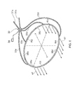
Figure 6 is a schematic illustration of part of the active control flow arrangement. Shown are twosupply pipes supply pipes valve arrangement 30 andfurther pipes compressed gas 47 to four zones or regions R1, R2, R3 and R4 around the circumference of theintake 11. The circumferential regions R1, R2, R3 and R4 comprise a lower region (R4), side regions (R1, R3) and an upper region (R2). - The
valve arrangement 30 is operable viacontroller 34 to select either one of the two (or more) compressed gas supplies or both simultaneously. Thevalve arrangement 30 is operable viacontroller 34 to select which pipe orpipes gas 47 to which of the four (or more) zones or regions R1, R2, R3 and R4. - The two gas supplies are from two sources of different pressures and thus the pressure of the gas can be delivered in any desired quantity or temperature to any part of the
intake surface 28. The two or more sources of compressed gas can be from different stages of the same compressor and/or different compressor including the intermediate and high pressure compressors as well as the low pressure compressor or fan. - In
Figure 7 the array of perforations or holes 58 comprises at least a first set ofholes 58A and a second set ofholes 58B. The first set ofholes 58A are arranged to primarily to attenuate acoustic pressure waves travelling through theintake 11. The second set ofholes 58B are arranged to feed or inject relatively warmer/hottercompressed gas 47 adjacent the facingsheet 41 to prevent or remove ice. As hereinbefore mentioned the second set ofholes 58B can also be used to prevent or reduce the formation of shock waves and / ormain gas flow 9 separation from thesurface 28. The first set ofholes 58A can be referred to as 'acoustic holes' and the second set ofholes 58B can be referred to as 'gas injection holes'; however in the embodiments below each type of hole may have some of the benefits of the other. - The first set of
holes 58A and the second set ofholes 58B have respective centre-lines radial line 60. Theradial line 60 is with respect to the main engine rotational axis X-X. Where theintake 11 is asymmetrical and/or drooped theradial line 60 may be with respect a centre of area line through the intake. The holes of first set ofholes 58A are angled α relative to the radial line and the holes of the second set of holes are angled β relative to the radial line; the angles α and β are different. - In one embodiment the holes of first set of
holes 58A are approximately normal to the surface and therefore angled α = 0°, i.e. parallel to the radial line. These holes are angled and arranged to attenuate acoustic pressure waves. For the primary purpose of attenuation the angle α may be between 0° and 15° from the radial line. The angle α may be rearwardly as shown inFigure 7 , forwardly and/or circumferentially with respect to the engine and may be a compound angle being circumferentially inclined and rearwardly or forwardly inclined. - The holes of the second set of
holes 58B have respective centre-lines 62B and define the angle β to theradial line 60. These holes are angled and arranged to supply relatively warm gas adjacent thesurface 28 to prevent ice accretion or remove ice already formed. The angle β is approximately 45°; however, β may be between 35° and 55° although the benefits of these holes can be achieved with an angle β between 15° and 75°. - Although each of the first set of
holes 58A and the second set ofholes 58B has a primary purpose each may also partially provide some of the benefits of the other. The first set ofholes 58A is supplied withcompressed gas flow 47 which enters the cell(s) 49 throughbacking sheet 42 viachamber 35. Thus thegas 47 can pass through theholes 58A to also prevent ice accretion or remove ice from thesurface 28. The second set ofholes 58B may also attenuate acoustic pressure waves present in the intake. Althoughgas flow 47 is passing out of the facingsheet 41 the pressure wave can still passes through thehole 58B to thecell 49 thereby being attenuate. Although the angle ofhole 58B is not ideal for attenuation, noise is still attenuated. - Furthermore and as herein described the first set of
holes 58A and / or the second set ofholes 58B may be used to supply the gas flow to the surface or boundary layer to prevent the formation of shock waves or prevent the formation of separation of the main gas flow from thesurface 28. Indeed the combination of the differently angledholes holes 58A enables the compressedgas flow 47 to penetrate further into themain gas flow 9, whereas theholes 58B enables the compressedgas flow 47 to be directed more closely to the surface. Thus the combination of normal and inclined holes gives a greater range of quantity and/or height above thesurface 28 that thecompressed gas flow 47 can be injected. - Referring now to
Figure 8 like elements are given the same reference numbers as previously described. In this embodiment, theholes 58A are not supplied with the compressedgas source 47. The hole(s) 58A fluidly connects acell 49A with theintake 11 and main gas flow passing 9. Anothercell 49B is associated with theholes 58B and has ahole 59 through thebacking sheet 42 to allowcompressed gas flow 47 into the cell and exit through thehole 58B in order for anti-icing use and/or shock wave suppression. -
Figures 9 and 10 show sections through a part of the facingsheet 41 and plan views of the radiallyinward surface 28 over whichmain gas flow 9 passes. These figures show some alternative configurations of theholes intake lining 40. These improvements relate to acoustic attenuation, suppression of main airflow separation from the surface, prevention of shock waves and anti-icing. Each hole configuration may be used in conjunction with any other or others in the array of holes. These holes may be inclined as hereinbefore described, in any direction or normal to thesurface 28. - In
Figures 9 and 10 , the axes X, Y, Z relate to the axial (engine rotational axis XX), the circumferential and radial directions respectively. - In
Figure 9 , the cross-sectional flow area ofhole 64A is convergent between the facing's radiallyouter surface 66 and radiallyinner surface main air flow 9. The convergence is in the direction of flow ofcompressed gas flow 47. - The cross-sectional flow area of
hole 64B is divergent between the facing's radiallyouter surface 66 and radiallyinner surface surface compressed gas flow 47. - The
holes main flow 9 direction. - The cross-sectional flow area of
hole 64C is convergent then divergent between the facing's radiallyouter surface 66 and radiallyinner surface - In
Figure 10 ,hole 64E diverges either in one or both the XZ plane and the XY plane so that theair flow 47 reduces in velocity as it passes out of the outlet. Relative to a constant cross sectional area hole, slowing the flow down means that the airflow will adhere to thesurface 28 better, whilst also spreading out more on thesurface 28 and therefore can be more effective for the same amount ofairflow 47 or operate with a reduced amount of airflow. - From a generally circular or ellipsoidal inlet,
hole 64F diverges in the XZ and XY planes to form an exit slot. A number of inlets may feed a single outlet slot. The airflow is slowed even further in this configuration as the outlet area can be greater than forhole 64E. -
Hole 64G converges in the XZ plane, but diverges in the XY plane so that its inlet and outlet areas are approximately equal, although the outlet's area can be more or less than the inlet area. Theairflow 47 therefore enters and exits thehole 64G at approximately the same velocity. These holes are useful to inject compressed gas into the main airflow above thesurface 28. -
Hole 64H diverges only in the XY plane to form an outlet slot. The hole may also converge in the XZ plane. A number of inlets may feed the single outlet slot thereby forming a even distribution of compressed gas over thesurface 28. - The various hole configurations and combinations enable each
liner 40 to be optimized to attenuate acoustic pressure waves, prevent the formation of shock waves and / ormain gas flow 9 separations from thesurface 28 and prevent ice from forming and/or remove ice formations. All of these hole configurations may be utilised to inject the compressedgas 47 into or above the boundary layer of the main gas flow passing oversurface 28. - Thus selection of position and configurations of these holes will enable minimisation of the impact of anti-icing gas flow on the main gas flow in terms of minimising drag and boundary layer thickening.
- These hole configurations can maximise the heat transfer performance of the anti-icing flow, thus requiring less anti-icing gas mass-flow which helps to minimise the use of parasitic bleed from a compressor or other compressed gas source.
- The hole configurations shown in
figures 9 and 10 are primarily used for anti-icing and / or prevention of the formation of shock waves and / or boundary layer separation. These hole configurations also provide some acoustic attenuation, although when implemented in conjunction with the 'acoustic holes' 58A described with reference toFigures 7 and 8 , theoverall liner 40 having an arrangement or combination of acoustic and gas flow holes. - Referring back to
Figure 1 , further the activeflow control arrangement 30 comprises at least onesensor controller 34 which controls thevalve arrangement 30 to control the supply of compressed gas to theintake surface 28. An array ofsensors flow control arrangement 30 is capable of supplyingcontrol gas 47 to any one or more regions of theintake surface 28 where a sensor senses a parameter that passes a predetermined threshold value indicative of the possibility of flow separation. - The
gas turbine engine 10 may be operated by determining a possible formation of separation of the main air flow from thesurface 28 and blowing compressor gas onto the surface or into a boundary layer adjacent the surface to prevent separation of the main air flow from thesurface 28. Using the above described apparatus, determining the axial and/or circumferential location(s) of a possible formation of separation of the main air flow from the surface (28) enables a minimum amount of control gas to be supplied. Off-taking compressed gas from a compressor can be detrimental its performance and therefore engine efficiency so minimising the amount of compressed gas used is beneficial. - Where the active
flow control arrangement 30 comprisessensors intake 11 and their sensed parameters input to thecontroller 34 it is possible to determine the possible formation of separation of the main air flow from thesurface 28 comprises the steps of by sensing the parameter, in this case usually pressure, of the main gas flow over thesurface 28. The sensed pressure is then compared to a predetermined or threshold value where it is known that a possible formation of separation of the main air flow from thesurface 28 may occur. - Alternatively, the
controller 34, programmed with an algorithm, receives engine and / or flight operational parameters, and compares these to a predetermined or threshold value where it is known that a possible formation of separation of the main air flow from thesurface 28 may occur. The engine operational parameter(s) comprise any one or more or combination of a flight cycle condition, airspeed, an angle of incidence, an engine throttle position, cross-wind strength and direction and weight on wheels. - An efficient way of using compressed gas is by pulsing the flow. Pulsing may be either stopping and starting the flow or modulating the mass flow rate. Gas jets issuing from the holes not only inject a quantity of air into the main gas flow but the jet causes secondary vortices to form around it and which help stabilise and/or reduce the formation of separation. Where the jets are pulsed these secondary vortices persist downstream even after the jet is reduced or switched off. Thus by pulsing the supply of gas to the holes that form the jets, the same beneficial effect of separation suppression can be realised with a significantly reduced high pressure bleed flow and improved system efficiency.
- The active flow control arrangement and its method of use is intended to prevent possible formation of separation of the main air flow from the
surface 28. However, by combining the apparatus and method of using it with an acoustic liner the benefits of both can still be achieved. Indeed the perforations in the lining 41 can be used to supply the control gas to the surface and / or the boundary layer to re-energise the main flow. - Where environmental conditions exist to cause possible ice formations on the intake, the active flow control arrangement can also be operated to supply heated compressed gas to the surface of the intake and thereby prevent ice build up. The control valves are operable to impart pulsing to the anti-ice gas flow through the (acoustic) liner to maximise shock suppression, while minimising the use of anti ice air. In this case, the
sensors EEC 34 may decide to preferentially use hotter gas from a different source either mixed or discreet for anti-icing measures rather than possibly cooler gas for preventing main air flow separation. - Thus there is disclosed an active flow control arrangement which is capable of delivering a control gas to the intake of a gas turbine engine to help prevent main air flow separation and/or ice accretion while attenuating noise from the turbomachinery. The active flow control arrangement provides minimal use of compressed gas and weight reduction, while greatly improving the quality of the main air flow into the engine for improved operational performance and reduction of damage.
- Other embodiments will be apparent to the skilled person from the teachings herein. For example, where a double layer liner is used the compressed gas supply could be routed circumferentially and/or axially through the radially outer layer of spacer material. Thus the
distribution network 50 is formed by the radially outer layer of spacer material.
Claims (15)
- A gas turbine engine (10) having a rotational axis (X-X), an intake (11) and a compressed gas source (12, 13, 14);
the intake is arranged about the rotational axis and includes a lining (40) having a facing (41) which defines an inlet surface (28) and an array of holes (58);
the array of holes (58) comprises at least a first set of holes (58A) and a second set of holes (58B), the holes of the first set of holes are angled α relative to a radial line with respect to the rotational axis and the holes of the second set of holes are angled β relative to the radial line; the angles α and β are different;
the second set of holes is connected to the compressed gas source. - A gas turbine engine (10) as claimed in claim 1 wherein the angle α is between 0° and 15°.
- A gas turbine engine (10) as claimed in claim 1 wherein the angle α is approximately 0°.
- A gas turbine engine (10) as claimed in any one of claims 1-3 wherein the angle β is between 15° and 75°.
- A gas turbine engine (10) as claimed in any one of claims 1-3 wherein the angle β is between 35° and 55°.
- A gas turbine engine (10) as claimed in any one of claims 1-3 wherein the angle β is approximately 45°.
- A gas turbine engine (10) as claimed in any one of claims 1-6 wherein the first set of holes (58A) is arranged to attenuate acoustic pressure waves and the second set of holes (58B) is arranged to prevent icing and/or the formation of shock waves and/or boundary layer separation.
- A gas turbine engine (10) as claimed in any one of claims 1-7 wherein the second set of holes (58B) comprises holes (64A, 64C, 64G, 64H) that converge between their inlet (70) and outlet (72).
- A gas turbine engine (10) as claimed in any one of claims 1-7 wherein the second set of holes (58B) comprises holes that diverge (64B, 64C, 64E, 64F, 64G, 64H) between their inlet (70) and outlet (72).
- A gas turbine engine (10) as claimed in any one of claims 1-7 wherein the second set of holes (58B) comprises holes (64G, 64H) that converge and diverge in mutually perpendicular directions between their inlet (70) and outlet (72).
- A gas turbine engine (10) as claimed in any one of claims 8-10 wherein the outlet (72) is a slot.
- A gas turbine engine (10) as claimed in any one of claims 8-11 wherein the second set of holes (58B) comprises holes (64H) having discrete inlets (70) and a common outlet (72).
- A gas turbine engine (10) as claimed in any one of claims 1-12 wherein the second set of holes (58B) is supplied with a compressed gas (47).
- A gas turbine engine (10) as claimed in claim 8 wherein the second set of holes (58B) is supplied with a compressed gas (47) only during conditions where anti-icing and/or prevention of the formation of shock waves and/or boundary layer separation may occur.
- A gas turbine engine (10) comprising an intake (11) defining an inlet surface (28), a compressed gas source (12, 13, 14) and an active flow control arrangement (30);
the intake includes a lining (40) having a facing (41) which defines an inlet surface (28) and an array of holes (58);
the array of holes (58) comprises at least a first set of holes (58A) and a second set of holes (58B), the holes of the first set of holes are angled α relative to a radial line and the holes of the second set of holes are angled β relative to the radial line;
the active flow control arrangement (30) comprising a compressed gas supply pipe (31), a valve arrangement (30), a controller (34), a compressed gas distribution pipe (33);
the supply pipe fluidly connects between the compressed gas source and the valve arrangement and the distribution pipe (33) fluidly connects between the valve arrangement and intake surface for supply of compressed gas thereto;
the active flow control arrangement (30) is operable to supply compressed gas to the intake surface to prevent separation of a main air flow (9) passing through the intake from the inlet surface.
Applications Claiming Priority (1)
| Application Number | Priority Date | Filing Date | Title |
|---|---|---|---|
| GB201121887A GB201121887D0 (en) | 2011-12-20 | 2011-12-20 | Intake liner for a gas turbine engine |
Publications (2)
| Publication Number | Publication Date |
|---|---|
| EP2607655A2 true EP2607655A2 (en) | 2013-06-26 |
| EP2607655A3 EP2607655A3 (en) | 2017-05-03 |
Family
ID=45572698
Family Applications (1)
| Application Number | Title | Priority Date | Filing Date |
|---|---|---|---|
| EP12196982.8A Withdrawn EP2607655A3 (en) | 2011-12-20 | 2012-12-13 | Intake liner for a gas turbine engine |
Country Status (3)
| Country | Link |
|---|---|
| US (1) | US8931252B2 (en) |
| EP (1) | EP2607655A3 (en) |
| GB (1) | GB201121887D0 (en) |
Cited By (6)
| Publication number | Priority date | Publication date | Assignee | Title |
|---|---|---|---|---|
| WO2015071609A1 (en) * | 2013-11-15 | 2015-05-21 | Aircelle | Device for de-icing the inlet of a nacelle of an aircraft engine, method for producing such a de-icing device, and aircraft engine nacelle provided with such a de-icing device |
| CN106089440A (en) * | 2016-06-13 | 2016-11-09 | 金能科技股份有限公司 | A kind of gas turbine inlet dehumanization method and system |
| EP3470652A1 (en) * | 2017-10-13 | 2019-04-17 | Rolls-Royce plc | Gas turbine engine vortex suppressor |
| EP3590841A1 (en) * | 2018-07-03 | 2020-01-08 | Rohr, Inc. | Inlet - nai exhaust hole definition for reduced d-duct resonance noise and diluted exhaust plume for thermal control |
| FR3087477A1 (en) * | 2018-10-22 | 2020-04-24 | Safran Aircraft Engines | DEVICE FOR DEFROSTING A TURBOMACHINE SPOUT |
| US10995670B2 (en) | 2012-10-26 | 2021-05-04 | Powerphase International, Llc | Gas turbine energy supplementing systems and heating systems, and methods of making and using the same |
Families Citing this family (19)
| Publication number | Priority date | Publication date | Assignee | Title |
|---|---|---|---|---|
| JP6039056B2 (en) | 2012-04-02 | 2016-12-07 | パワーフェイズ・エルエルシー | Compressed air injection system method and apparatus for gas turbine engine |
| US9758240B2 (en) * | 2014-04-25 | 2017-09-12 | Rohr, Inc. | Modular plenum and duct system for controlling boundary layer airflow |
| GB201511454D0 (en) | 2015-06-30 | 2015-08-12 | Rolls Royce Plc | Aircraft engine nacelle |
| US10486821B2 (en) * | 2015-07-07 | 2019-11-26 | The Boeing Company | Jet engine anti-icing and noise-attenuating air inlets |
| US10655539B2 (en) * | 2017-10-16 | 2020-05-19 | Rolls-Royce North America Technologies Inc. | Aircraft anti-icing system |
| US10934807B2 (en) * | 2018-12-25 | 2021-03-02 | Kaz Jon Anderson | Horizontal directional drill rig heating system |
| FR3092620B1 (en) * | 2019-02-08 | 2021-03-05 | Safran Nacelles | Air inlet of an aircraft turbojet nacelle having ventilation openings for a flow of hot de-icing air |
| FR3092619B1 (en) | 2019-02-08 | 2021-03-19 | Safran Nacelles | Air inlet of an aircraft turbojet nacelle having ventilation openings for a flow of hot de-icing air |
| FR3092618B1 (en) | 2019-02-08 | 2021-02-19 | Safran Nacelles | Air inlet of an aircraft turbojet nacelle having ventilation openings for a flow of hot de-icing air |
| US11260641B2 (en) | 2019-05-10 | 2022-03-01 | American Honda Motor Co., Inc. | Apparatus for reticulation of adhesive and methods of use thereof |
| FR3100842A1 (en) * | 2019-09-12 | 2021-03-19 | Airbus Operations | Air inlet, nacelle, propulsion assembly and grooved lip aircraft |
| CN112709637B (en) * | 2019-10-25 | 2022-05-10 | 中国航发商用航空发动机有限责任公司 | Device and method for improving crosswind resistance of air inlet channel of nacelle of aero-engine |
| US11577843B2 (en) | 2019-11-05 | 2023-02-14 | Rohr, Inc. | Thermal anti-icing system with non-circular piccolo tube |
| US11577844B2 (en) | 2020-03-12 | 2023-02-14 | Rohr, Inc. | Variable diameter piccolo tube for anti-icing system |
| US11828237B2 (en) | 2020-04-28 | 2023-11-28 | General Electric Company | Methods and apparatus to control air flow separation of an engine |
| US11333079B2 (en) | 2020-04-28 | 2022-05-17 | General Electric Company | Methods and apparatus to detect air flow separation of an engine |
| US11686246B2 (en) * | 2021-10-15 | 2023-06-27 | Gulfstream Aerospace Corporation | Propulsion system for an aircraft |
| US11834997B2 (en) * | 2022-04-29 | 2023-12-05 | Rtx Corporation | Face sheet of acoustic liner having streamlined holes with elongated edges |
| US20250304266A1 (en) * | 2024-03-27 | 2025-10-02 | Airbus (S.A.S.) | Cooling of gas flowing over aircraft structure |
Family Cites Families (17)
| Publication number | Priority date | Publication date | Assignee | Title |
|---|---|---|---|---|
| FR2370171A1 (en) * | 1976-11-05 | 1978-06-02 | Snecma | METHOD AND DEVICE FOR REDUCING TURBOMACHINE NOISE |
| US4749150A (en) | 1985-12-24 | 1988-06-07 | Rohr Industries, Inc. | Turbofan duct with noise suppression and boundary layer control |
| US4738416A (en) * | 1986-09-26 | 1988-04-19 | Quiet Nacelle Corporation | Nacelle anti-icing system |
| US5114100A (en) * | 1989-12-29 | 1992-05-19 | The Boeing Company | Anti-icing system for aircraft |
| US5447283A (en) | 1994-02-02 | 1995-09-05 | Grumman Aerospace Corporation | Blown boundary layer control system for a jet aircraft |
| US5721402A (en) * | 1996-09-09 | 1998-02-24 | Northrop Grumman Corporation | Noise suppression system for a jet engine |
| US5841079A (en) | 1997-11-03 | 1998-11-24 | Northrop Grumman Corporation | Combined acoustic and anti-ice engine inlet liner |
| US6138950A (en) * | 1998-10-06 | 2000-10-31 | Northrop Grumman Corporation | Aircraft engine air intake system |
| FR2820716B1 (en) * | 2001-02-15 | 2003-05-30 | Eads Airbus Sa | PROCESS FOR DEFROSTING BY FORCED CIRCULATION OF A FLUID, OF A REACTION ENGINE AIR INLET COVER AND DEVICE FOR ITS IMPLEMENTATION |
| JP3809520B2 (en) | 2001-07-04 | 2006-08-16 | 独立行政法人 宇宙航空研究開発機構 | Fine jet control sound absorption system |
| US7617670B2 (en) * | 2006-03-31 | 2009-11-17 | Lockheed Martin Corporation | Flow control redistribution to mitigate high cycle fatigue |
| US7870721B2 (en) * | 2006-11-10 | 2011-01-18 | United Technologies Corporation | Gas turbine engine providing simulated boundary layer thickness increase |
| US7784732B2 (en) | 2007-01-04 | 2010-08-31 | The United States Of America As Represented By The Administrator Of The National Aeronautics And Space Administration | Boundary-layer-ingesting inlet flow control system |
| FR2914773B1 (en) | 2007-04-04 | 2012-12-14 | Airbus France | PROCESS FOR PRODUCING AN ACOUSTICALLY RESISTIVE STRUCTURE, ACOUSTICALLY RESISTIVE STRUCTURE THUS OBTAINED AND COATING USING SUCH A STRUCTURE |
| US20100206664A1 (en) | 2007-07-12 | 2010-08-19 | Rolls-Royce Plc | Acoustic panel |
| US9004399B2 (en) * | 2007-11-13 | 2015-04-14 | United Technologies Corporation | Nacelle flow assembly |
| US8192147B2 (en) * | 2007-12-14 | 2012-06-05 | United Technologies Corporation | Nacelle assembly having inlet bleed |
-
2011
- 2011-12-20 GB GB201121887A patent/GB201121887D0/en not_active Ceased
-
2012
- 2012-12-13 EP EP12196982.8A patent/EP2607655A3/en not_active Withdrawn
- 2012-12-13 US US13/713,840 patent/US8931252B2/en active Active
Non-Patent Citations (1)
| Title |
|---|
| None * |
Cited By (14)
| Publication number | Priority date | Publication date | Assignee | Title |
|---|---|---|---|---|
| US10995670B2 (en) | 2012-10-26 | 2021-05-04 | Powerphase International, Llc | Gas turbine energy supplementing systems and heating systems, and methods of making and using the same |
| US11686250B2 (en) | 2012-10-26 | 2023-06-27 | Powerphase Llc | Gas turbine energy supplementing systems and heating systems, and methods of making and using the same |
| FR3013329A1 (en) * | 2013-11-15 | 2015-05-22 | Aircelle Sa | AIRCRAFT AIR ENTRY DEFROSTING DEVICE OF AN AIRCRAFT ENGINE, METHOD OF MANUFACTURING SUCH A DEFROSTING DEVICE, AND AIRCRAFT ENGINE NACELLE EQUIPPED WITH SUCH A DEFROSTING DEVICE |
| CN105764794A (en) * | 2013-11-15 | 2016-07-13 | 埃尔塞乐公司 | Device for de-icing an inlet of a nacelle of an aircraft engine, method for producing the de-icing device, and the aircraft engine nacelle provided with the de-icing device |
| CN105764794B (en) * | 2013-11-15 | 2018-03-13 | 埃尔塞乐公司 | The deicer and its manufacture method of aircraft engine nacelle entrance, and aircraft engine nacelle |
| WO2015071609A1 (en) * | 2013-11-15 | 2015-05-21 | Aircelle | Device for de-icing the inlet of a nacelle of an aircraft engine, method for producing such a de-icing device, and aircraft engine nacelle provided with such a de-icing device |
| US10532820B2 (en) | 2013-11-15 | 2020-01-14 | Aircelle | Device for de-icing the inlet of a nacelle of an aircraft engine, method for producing such a de-icing device, and aircraft engine nacelle provided with such a de-icing device |
| CN106089440A (en) * | 2016-06-13 | 2016-11-09 | 金能科技股份有限公司 | A kind of gas turbine inlet dehumanization method and system |
| EP3470652A1 (en) * | 2017-10-13 | 2019-04-17 | Rolls-Royce plc | Gas turbine engine vortex suppressor |
| EP3590841A1 (en) * | 2018-07-03 | 2020-01-08 | Rohr, Inc. | Inlet - nai exhaust hole definition for reduced d-duct resonance noise and diluted exhaust plume for thermal control |
| US11208952B2 (en) | 2018-07-03 | 2021-12-28 | Rohr, Inc. | Inlet—NAI exhaust hole definition for reduced D-duct resonance noise and diluted exhaust plume for thermal control |
| WO2020084248A1 (en) * | 2018-10-22 | 2020-04-30 | Safran Aircraft Engines | Device for de-icing a turbomachine nozzle |
| FR3087477A1 (en) * | 2018-10-22 | 2020-04-24 | Safran Aircraft Engines | DEVICE FOR DEFROSTING A TURBOMACHINE SPOUT |
| US12359614B2 (en) * | 2018-10-22 | 2025-07-15 | Safran Aircraft Engines | Device for de-icing a turbomachine nozzle |
Also Published As
| Publication number | Publication date |
|---|---|
| US8931252B2 (en) | 2015-01-13 |
| GB201121887D0 (en) | 2012-02-01 |
| EP2607655A3 (en) | 2017-05-03 |
| US20130263601A1 (en) | 2013-10-10 |
Similar Documents
| Publication | Publication Date | Title |
|---|---|---|
| US8931252B2 (en) | Intake liner for a gas turbine engine | |
| EP2607657A2 (en) | Active flow control intake for a gas turbine engine | |
| US8209953B2 (en) | Gas turbine engine system providing simulated boundary layer thickness increase | |
| US11162417B2 (en) | Scoop inlet | |
| JP6030940B2 (en) | System and method for active clearance control | |
| EP3190286A1 (en) | Gas turbine engine | |
| EP2481893B1 (en) | Heated booster splitter plenum | |
| US7950218B2 (en) | Bypass turbomachine with artificial variation of its throat section | |
| US8192147B2 (en) | Nacelle assembly having inlet bleed | |
| EP3483414B1 (en) | Gas turbine engine having an air-oil heat exchanger | |
| EP3096023B1 (en) | Gas turbine with compressor blade tip injector | |
| US8955304B2 (en) | Gas turbine engine with modular cores and propulsion unit | |
| JP5925561B2 (en) | Flow device and method and system using the flow device | |
| EP2472081B1 (en) | Variable cycle gas turbine engine | |
| EP1998027B1 (en) | Gas turbine engine comprising a nacelle compartment plenum for bleed air flow delivery system | |
| US20090121083A1 (en) | Nacelle Flow Assembly | |
| US8206079B2 (en) | Temperature controlling apparatus | |
| EP2685065B1 (en) | Propeller gas turbine engine | |
| US11884414B2 (en) | Supersonic aircraft turbofan engine | |
| GB2443830A (en) | Gas turbine engine bypass duct wall cooling arrangement | |
| US10378439B2 (en) | Gas turbine engine with variable speed turbines | |
| WO2008045051A2 (en) | Gas turbine nacelle comprising a passive boundary lazer bleed system and method of controlling turbulent airflow | |
| EP2497904B1 (en) | Gas turbine engine rotor cooling with swirled cooling air | |
| US20170175629A1 (en) | Gas turbine engine with short inlet and anti-icing features | |
| JPH0526944B2 (en) |
Legal Events
| Date | Code | Title | Description |
|---|---|---|---|
| AK | Designated contracting states |
Kind code of ref document: A2 Designated state(s): AL AT BE BG CH CY CZ DE DK EE ES FI FR GB GR HR HU IE IS IT LI LT LU LV MC MK MT NL NO PL PT RO RS SE SI SK SM TR |
|
| AX | Request for extension of the european patent |
Extension state: BA ME |
|
| PUAI | Public reference made under article 153(3) epc to a published international application that has entered the european phase |
Free format text: ORIGINAL CODE: 0009012 |
|
| RAP1 | Party data changed (applicant data changed or rights of an application transferred) |
Owner name: ROLLS-ROYCE PLC |
|
| PUAL | Search report despatched |
Free format text: ORIGINAL CODE: 0009013 |
|
| AK | Designated contracting states |
Kind code of ref document: A3 Designated state(s): AL AT BE BG CH CY CZ DE DK EE ES FI FR GB GR HR HU IE IS IT LI LT LU LV MC MK MT NL NO PL PT RO RS SE SI SK SM TR |
|
| AX | Request for extension of the european patent |
Extension state: BA ME |
|
| RIC1 | Information provided on ipc code assigned before grant |
Ipc: F02C 7/045 20060101ALI20170328BHEP Ipc: F02C 3/32 20060101ALI20170328BHEP Ipc: B64D 33/02 20060101ALI20170328BHEP Ipc: F02C 7/057 20060101ALI20170328BHEP Ipc: F02C 7/04 20060101ALI20170328BHEP Ipc: F02C 7/047 20060101AFI20170328BHEP |
|
| STAA | Information on the status of an ep patent application or granted ep patent |
Free format text: STATUS: REQUEST FOR EXAMINATION WAS MADE |
|
| 17P | Request for examination filed |
Effective date: 20171103 |
|
| RBV | Designated contracting states (corrected) |
Designated state(s): AL AT BE BG CH CY CZ DE DK EE ES FI FR GB GR HR HU IE IS IT LI LT LU LV MC MK MT NL NO PL PT RO RS SE SI SK SM TR |
|
| STAA | Information on the status of an ep patent application or granted ep patent |
Free format text: STATUS: EXAMINATION IS IN PROGRESS |
|
| 17Q | First examination report despatched |
Effective date: 20180313 |
|
| RAP1 | Party data changed (applicant data changed or rights of an application transferred) |
Owner name: ROLLS-ROYCE PLC |
|
| STAA | Information on the status of an ep patent application or granted ep patent |
Free format text: STATUS: THE APPLICATION HAS BEEN WITHDRAWN |
|
| 18W | Application withdrawn |
Effective date: 20200407 |