EP2607627B1 - Fan blade with composite core and wavy wall trailing edge cladding - Google Patents
Fan blade with composite core and wavy wall trailing edge cladding Download PDFInfo
- Publication number
- EP2607627B1 EP2607627B1 EP12196898.6A EP12196898A EP2607627B1 EP 2607627 B1 EP2607627 B1 EP 2607627B1 EP 12196898 A EP12196898 A EP 12196898A EP 2607627 B1 EP2607627 B1 EP 2607627B1
- Authority
- EP
- European Patent Office
- Prior art keywords
- trailing edge
- airfoil
- composite core
- cladding
- pressure
- Prior art date
- Legal status (The legal status is an assumption and is not a legal conclusion. Google has not performed a legal analysis and makes no representation as to the accuracy of the status listed.)
- Not-in-force
Links
- 239000002131 composite material Substances 0.000 title claims description 50
- 238000005253 cladding Methods 0.000 title claims description 28
- 239000000463 material Substances 0.000 claims description 12
- 229910052751 metal Inorganic materials 0.000 claims description 5
- 239000002184 metal Substances 0.000 claims description 5
- 239000011248 coating agent Substances 0.000 claims description 3
- 238000000576 coating method Methods 0.000 claims description 3
- 230000003628 erosive effect Effects 0.000 claims description 3
- 239000007789 gas Substances 0.000 description 7
- 239000000835 fiber Substances 0.000 description 4
- 238000000034 method Methods 0.000 description 3
- 238000011144 upstream manufacturing Methods 0.000 description 3
- VYPSYNLAJGMNEJ-UHFFFAOYSA-N Silicium dioxide Chemical compound O=[Si]=O VYPSYNLAJGMNEJ-UHFFFAOYSA-N 0.000 description 2
- 239000011159 matrix material Substances 0.000 description 2
- 238000012986 modification Methods 0.000 description 2
- 230000004048 modification Effects 0.000 description 2
- 230000008569 process Effects 0.000 description 2
- 229920005989 resin Polymers 0.000 description 2
- 239000011347 resin Substances 0.000 description 2
- 239000004593 Epoxy Substances 0.000 description 1
- FYYHWMGAXLPEAU-UHFFFAOYSA-N Magnesium Chemical compound [Mg] FYYHWMGAXLPEAU-UHFFFAOYSA-N 0.000 description 1
- BPQQTUXANYXVAA-UHFFFAOYSA-N Orthosilicate Chemical compound [O-][Si]([O-])([O-])[O-] BPQQTUXANYXVAA-UHFFFAOYSA-N 0.000 description 1
- 239000000853 adhesive Substances 0.000 description 1
- 230000001070 adhesive effect Effects 0.000 description 1
- PNEYBMLMFCGWSK-UHFFFAOYSA-N aluminium oxide Inorganic materials [O-2].[O-2].[O-2].[Al+3].[Al+3] PNEYBMLMFCGWSK-UHFFFAOYSA-N 0.000 description 1
- 230000000712 assembly Effects 0.000 description 1
- 238000000429 assembly Methods 0.000 description 1
- 239000011230 binding agent Substances 0.000 description 1
- 239000000919 ceramic Substances 0.000 description 1
- 239000000567 combustion gas Substances 0.000 description 1
- 238000004891 communication Methods 0.000 description 1
- 238000013461 design Methods 0.000 description 1
- 239000003822 epoxy resin Substances 0.000 description 1
- 238000011156 evaluation Methods 0.000 description 1
- 239000000446 fuel Substances 0.000 description 1
- 239000011521 glass Substances 0.000 description 1
- 239000003365 glass fiber Substances 0.000 description 1
- 230000003993 interaction Effects 0.000 description 1
- 229910052749 magnesium Inorganic materials 0.000 description 1
- 239000011777 magnesium Substances 0.000 description 1
- 238000004519 manufacturing process Methods 0.000 description 1
- 239000007769 metal material Substances 0.000 description 1
- 229910044991 metal oxide Inorganic materials 0.000 description 1
- 150000004706 metal oxides Chemical class 0.000 description 1
- 238000000465 moulding Methods 0.000 description 1
- 239000002245 particle Substances 0.000 description 1
- 229920000647 polyepoxide Polymers 0.000 description 1
- 230000009467 reduction Effects 0.000 description 1
- 230000002787 reinforcement Effects 0.000 description 1
- 230000003014 reinforcing effect Effects 0.000 description 1
- 239000000377 silicon dioxide Substances 0.000 description 1
Images
Classifications
-
- F—MECHANICAL ENGINEERING; LIGHTING; HEATING; WEAPONS; BLASTING
- F01—MACHINES OR ENGINES IN GENERAL; ENGINE PLANTS IN GENERAL; STEAM ENGINES
- F01D—NON-POSITIVE DISPLACEMENT MACHINES OR ENGINES, e.g. STEAM TURBINES
- F01D5/00—Blades; Blade-carrying members; Heating, heat-insulating, cooling or antivibration means on the blades or the members
- F01D5/12—Blades
- F01D5/28—Selecting particular materials; Particular measures relating thereto; Measures against erosion or corrosion
- F01D5/282—Selecting composite materials, e.g. blades with reinforcing filaments
-
- F—MECHANICAL ENGINEERING; LIGHTING; HEATING; WEAPONS; BLASTING
- F01—MACHINES OR ENGINES IN GENERAL; ENGINE PLANTS IN GENERAL; STEAM ENGINES
- F01D—NON-POSITIVE DISPLACEMENT MACHINES OR ENGINES, e.g. STEAM TURBINES
- F01D5/00—Blades; Blade-carrying members; Heating, heat-insulating, cooling or antivibration means on the blades or the members
- F01D5/12—Blades
- F01D5/14—Form or construction
- F01D5/141—Shape, i.e. outer, aerodynamic form
-
- F—MECHANICAL ENGINEERING; LIGHTING; HEATING; WEAPONS; BLASTING
- F05—INDEXING SCHEMES RELATING TO ENGINES OR PUMPS IN VARIOUS SUBCLASSES OF CLASSES F01-F04
- F05D—INDEXING SCHEME FOR ASPECTS RELATING TO NON-POSITIVE-DISPLACEMENT MACHINES OR ENGINES, GAS-TURBINES OR JET-PROPULSION PLANTS
- F05D2220/00—Application
- F05D2220/30—Application in turbines
- F05D2220/36—Application in turbines specially adapted for the fan of turbofan engines
-
- F—MECHANICAL ENGINEERING; LIGHTING; HEATING; WEAPONS; BLASTING
- F05—INDEXING SCHEMES RELATING TO ENGINES OR PUMPS IN VARIOUS SUBCLASSES OF CLASSES F01-F04
- F05D—INDEXING SCHEME FOR ASPECTS RELATING TO NON-POSITIVE-DISPLACEMENT MACHINES OR ENGINES, GAS-TURBINES OR JET-PROPULSION PLANTS
- F05D2240/00—Components
- F05D2240/20—Rotors
- F05D2240/30—Characteristics of rotor blades, i.e. of any element transforming dynamic fluid energy to or from rotational energy and being attached to a rotor
- F05D2240/304—Characteristics of rotor blades, i.e. of any element transforming dynamic fluid energy to or from rotational energy and being attached to a rotor related to the trailing edge of a rotor blade
-
- F—MECHANICAL ENGINEERING; LIGHTING; HEATING; WEAPONS; BLASTING
- F05—INDEXING SCHEMES RELATING TO ENGINES OR PUMPS IN VARIOUS SUBCLASSES OF CLASSES F01-F04
- F05D—INDEXING SCHEME FOR ASPECTS RELATING TO NON-POSITIVE-DISPLACEMENT MACHINES OR ENGINES, GAS-TURBINES OR JET-PROPULSION PLANTS
- F05D2250/00—Geometry
- F05D2250/10—Two-dimensional
- F05D2250/18—Two-dimensional patterned
- F05D2250/184—Two-dimensional patterned sinusoidal
-
- Y—GENERAL TAGGING OF NEW TECHNOLOGICAL DEVELOPMENTS; GENERAL TAGGING OF CROSS-SECTIONAL TECHNOLOGIES SPANNING OVER SEVERAL SECTIONS OF THE IPC; TECHNICAL SUBJECTS COVERED BY FORMER USPC CROSS-REFERENCE ART COLLECTIONS [XRACs] AND DIGESTS
- Y02—TECHNOLOGIES OR APPLICATIONS FOR MITIGATION OR ADAPTATION AGAINST CLIMATE CHANGE
- Y02T—CLIMATE CHANGE MITIGATION TECHNOLOGIES RELATED TO TRANSPORTATION
- Y02T50/00—Aeronautics or air transport
- Y02T50/60—Efficient propulsion technologies, e.g. for aircraft
Definitions
- the invention relates to rotary machine and gas turbine engine rotor and stator airfoils and, particularly, to composite rotors and stator airfoils.
- Aircraft turbine engines and other type of rotary machines include stationary and rotating airfoils which channel an airflow downstream. As a result, a wake flow may be generated and channeled downstream where it may impinge against an object downstream from the airfoils. Wake flow impingement may generate undesirable noise and/or aeromechanical loading. Unwanted noise may be generated by either the upstream rotating airfoil wake impinging on a stator or rotor component downstream from the rotating airfoil, or the upstream stator airfoil wake impinging on a rotating airfoil downstream from the stator airfoil.
- the generation of such wake flow may result in a loss of engine performance and engine efficiency.
- Reduction of the amplitude of the wake flow may reduce the noise and the aeromechanical loading generated when the wake impinges against a downstream object.
- An airfoil designed to reduce the amplitude and/or coherence of the wake flow, the noise, and the aeromechanical loading is disclosed in United States Patent No. 8,083,487 , entitled "AIRFOILS FOR USE IN ROTARY MACHINES AND METHOD FOR FABRICATING SAME", by Trevor Howard Wood et al., which issued December 27, 2011 and is incorporated herein by reference.
- the airfoil includes suction and pressure sides coupled together at a leading edge and a trailing edge, wherein the airfoil includes a plurality of first and second chord sections each extending between the trailing and leading edges, wherein at least one of the first chord sections extends outward from the pressure side of the airfoil at the trailing edge, and at least one of the second chord sections extends outward from the suction side of the airfoil at the trailing edge.
- Particular embodiments of the airfoil are wavy or crenelated airfoils.
- Composite fan blades have been developed for aircraft gas turbine engines to reduce weight and cost, particularly for blades in larger engines.
- a large engine composite wide chord fan blades offer a significant weight savings over a large engine having standard chorded fan blades.
- the term composite as used herein may be defined as a material containing a reinforcement such as fibers or particles supported in a binder or matrix material.
- Composites include metallic and non-metallic composites.
- One particularly useful embodiment for fan composite fan blades is made of a unidirectional tape material and an epoxy resin matrix.
- the composite fan blade and other airfoils disclosed herein may include composite materials of the non-metallic type made of a material containing a fiber such as a carbonaceous, silica, metal, metal oxide, or ceramic fiber embedded in a resin material such as Epoxy, PMR15, BMI, PEEU, etc.
- a more particular material includes fibers unidirectionally aligned into a tape that is impregnated with a resin, formed into a part shape, and cured via an autoclaving process or press molding to form a light-weight, stiff, relatively homogeneous article having laminates within.
- EP1,574,270 A1 relates to a process for manufacturing a reinforcing leading or trailing edge for a fan blade and discloses features generally corresponding to the preamble of claim 1 herein.
- a gas turbine engine airfoil is provided in accordance with claim 1 herein.
- the airfoil comprises pressure and suction side flanks of the trailing edge cladding bonded to pressure and suction side surfaces respectively of the trailing edge portion of the composite core. Waves of the wavy wall may extend normal to and away from the pressure and suction side surfaces.
- the trailing edge cladding may be metallic and may include spanwise extending wavy pressure and suction side trailing edge guards which include the waves of the wavy wall.
- either an erosion coating is used to cover the composite core and butt up against and hide the forward facing steps on the pressure and suction side flanks of the trailing edge cladding, or alternatively, rebates extend into the composite core and hide the steps.
- a gas turbine engine fan blade is also provided in accordance with claim 5 herein.
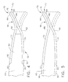
- FIG. 4 is a cross-sectional view illustration of a first alternative embodiment of the composite core trailing edge and metallic trailing edge of the blade illustrated in FIG. 3 .
- FIG. 5 is a cross-sectional view illustration of a second alternative embodiment of the composite core trailing edge and metallic trailing edge of the blade illustrated in FIG. 3 .
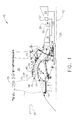
- FIG. 1 Illustrated in FIG. 1 is an exemplary aircraft turbofan gas turbine engine 10 circumscribed about an engine centerline axis 12 and suitably designed to be mounted to a wing or fuselage of an aircraft.
- the engine 10 includes, in downstream serial flow communication, a fan 14, a booster 16, a high pressure compressor 18, a combustor 20, a high pressure turbine (HPT) 22, and a low pressure turbine (LPT) 24.
- the HPT or high pressure turbine 22 is joined by a high pressure drive shaft 23 to the high pressure compressor 18.
- the LPT or low pressure turbine 24 is joined by a low pressure drive shaft 25 to both the fan 14 and the booster 16.
- air 26 is pressurized by a row of fan blades 11 in the fan 14 and produces an inner air flow 15 channeled through the booster 16 which further pressurizes the inner air flow 15.
- the pressurized air is then flowed to the high pressure compressor 18 which further pressurizes the air.
- the pressurized air is mixed with fuel in the combustor 20 for generating hot combustion gases 28 that flow downstream in turn through the HPT 22 and the LPT 24.
- a flow splitter 34 surrounding the booster 16 immediately behind the fan 14 includes a sharp leading edge 32 which splits the fan air 26 pressurized by the fan 14 into a radially inner stream (inner air flow 15) channeled through the booster 16 and a radially outer stream (bypass air flow 17) channeled through the bypass duct 36.
- a fan casing 30 surrounding the fan 14 is supported by an annular fan frame 33.
- the booster 16 includes alternating annular rows of booster blades and vanes 38, 42 extending radially outwardly and inwardly across a booster flowpath 39 in a booster duct 40.
- the annular rows of booster blades 38 are suitably joined to the fan 14.
- the booster 16 is located forward of the fan frame 33 and is disposed radially inboard of the flow splitter 34.
- the fan 14 includes a plurality of fan blades 11 that extend substantially radially outwardly from a fan rotor disk 13.
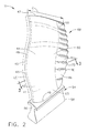
- FIG. 2 Illustrated in FIG. 2 is one embodiment of the fan blade 11 that may be used in engine 10 (illustrated in FIG. 1 ).
- the fan blade 11 includes an airfoil 45 extending outwardly from a platform 56 and a root 54 extending inwardly from the platform 56.
- airfoil 45 may be used with, but not limited to, rotor blades, stator vanes, and/or nozzle assemblies. Airfoil 45 may also be used with, OGVs and the booster.
- the root 54 includes an integral dovetail 58 that enables the fan blade 11 to be mounted to the rotor disk 13.
- the airfoil 45 includes pressure and suction sides 41, 43 extending outwardly in a spanwise direction along a span S from an airfoil base 49 at the platform 56 to an airfoil tip 47.
- the exemplary pressure and suction sides 41, 43 illustrated herein are concave and convex respectively.
- the airfoil 45 extends along a chord C between chordwise spaced apart leading and trailing edges LE, TE.
- the airfoil 45 may be mounted on and integral with a hub instead of the platform and disk to form an integrally bladed rotor (IBR).
- IBR integrally bladed rotor
- fan blade 11 may have any conventional form, with or without dovetail 58 or platform 56.
- fan blade 11 may be formed integrally with disk 13 in a blisk-type configuration that does not include the dovetail 58 and the platform is annular extending around the entire blisk.
- the airfoil 45 includes a composite core 44 and trailing edge cladding 46 that provides the airfoil's trailing edge TE.
- Demarcation line 59 indicates the intersection of the composite core 44 and metallic trailing edge cladding 46.
- the composite core 44 is made of a composite material, generally airfoil shaped, and incudes a central core portion 63 extending chordwise downstream from a leading edge portion 48 to a trailing edge portion 50 of the composite core 44.
- the trailing edge cladding 46 is made of any suitable material that is stronger or more ductile or less brittle than the composite material of the composite core 44.
- the trailing edge cladding material is illustrated herein as being metallic.
- Another less brittle and suitable cladding material is S-glass such as HS2 and HS4 which are high strength glass fibers made from magnesium alumina silicate.
- the leading edge portion 48 may or may not be covered by leading edge cladding 66 made of a metallic or other suitable material and which would then define the leading edge LE of the airfoil 45.
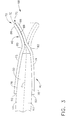
- the trailing edge cladding 46 includes a fluted or wavy wall 70 and the trailing edge TE designed to reduce noise during the engine's operation and, thus, lower the acoustic signature of the airfoil 45.
- the wavy wall 70 is designed to mix the fan wakes to reduce the wake interaction with downstream outlet guide vanes (OGV).
- the wavy wall 70 includes waves 68 such as crenelations or undulations 72. This allows the peak strain caused by the wavy wall 70, which is an aerodynamic feature stress, to be born by the metallic trailing edge cladding 46.
- the metallic trailing edge cladding 46 is far more capable of bearing strain than the composite core 44.
- the metallic trailing edge cladding 46 is bonded to the trailing edge portion 50 of the composite core 44.
- the bonding uses a film adhesive for example.
- the trailing edge cladding 46 includes pressure and suction side flanks 73, 74 that are bonded to pressure and suction side surfaces 76, 78 respectively of the trailing edge portion 50 of the composite core 44.
- the waves 68 of the wavy wall 70 extend normal to and away from the pressure and suction side surfaces 76, 78.
- the wavy wall 70 representative of a sculptured trailing edge (STE) feature, is entirely made of metal and better able to withstand peak stresses and strains that peak in the STE feature itself than composite airfoils or composite portions of airfoils.
- the metallic trailing edges have a higher strain capability as compared to the composite core based on pure material property evaluation. Bonding metallic STE features to the composite core allows stresses transferred to the composite core to be spread out over a large area and, thus, lowering localized stress and strain that may fail a composite airfoil.
- the airfoil 45 with the composite core 44 and the metallic trailing edge cladding 46 provides a more capable metallic material which increases robustness of the airfoil and provides weight advantages of composite materials.
- the exemplary embodiment of the metallic trailing edge cladding 46 illustrated in FIG. 3 includes radially or spanwise extending wavy pressure and suction side trailing edge guards 80, 82 made of sheet metal.
- the pressure and suction side trailing edge guards 80, 82 provide the wavy shape of the metallic trailing edge cladding 46.
- the metal cladding may be hot formed to shape.
- the pressure and suction side trailing edge guards 80, 82 are bonded to the pressure and suction side surfaces 76, 78 respectively of the composite core 44. Contacting pressure and suction side portions 86, 88 of the pressure and suction side trailing edge guards 80, 82 are bonded together as indicated along bond line 89.
- the pressure and suction side trailing edge guards 80, 82 diagrammatically illustrated in FIG. 3 have an upstream or forward facing step 90 that should be aerodynamically covered. Thus, this part of the metallic cladding is blended into the composite core 44.
- FIG. 4 illustrates one design to hide the step 90 by providing a small rebate 92 into the composite core 44 to keep the pressure and suction side flanks 73, 74 flush with the composite core 44.
- an erosion coating 96 butting up to the step 90 may be placed on the composite core 44.
Landscapes
- Engineering & Computer Science (AREA)
- Chemical & Material Sciences (AREA)
- Materials Engineering (AREA)
- Mechanical Engineering (AREA)
- General Engineering & Computer Science (AREA)
- Composite Materials (AREA)
- Physics & Mathematics (AREA)
- Fluid Mechanics (AREA)
- Structures Of Non-Positive Displacement Pumps (AREA)
Applications Claiming Priority (1)
| Application Number | Priority Date | Filing Date | Title |
|---|---|---|---|
| US13/331,301 US9121294B2 (en) | 2011-12-20 | 2011-12-20 | Fan blade with composite core and wavy wall trailing edge cladding |
Publications (2)
| Publication Number | Publication Date |
|---|---|
| EP2607627A1 EP2607627A1 (en) | 2013-06-26 |
| EP2607627B1 true EP2607627B1 (en) | 2015-03-25 |
Family
ID=47519843
Family Applications (1)
| Application Number | Title | Priority Date | Filing Date |
|---|---|---|---|
| EP12196898.6A Not-in-force EP2607627B1 (en) | 2011-12-20 | 2012-12-13 | Fan blade with composite core and wavy wall trailing edge cladding |
Country Status (6)
| Country | Link |
|---|---|
| US (1) | US9121294B2 (enExample) |
| EP (1) | EP2607627B1 (enExample) |
| JP (1) | JP6074253B2 (enExample) |
| CN (1) | CN103174676A (enExample) |
| BR (1) | BR102012031677A2 (enExample) |
| CA (1) | CA2798821A1 (enExample) |
Families Citing this family (31)
| Publication number | Priority date | Publication date | Assignee | Title |
|---|---|---|---|---|
| US20150063997A1 (en) * | 2013-08-29 | 2015-03-05 | General Electric Company | Airfoil trailing edge |
| JP2015075062A (ja) * | 2013-10-11 | 2015-04-20 | 株式会社日立製作所 | 軸流タイプブレードとそれを用いた風力発電用装置 |
| FR3023329B1 (fr) * | 2014-07-03 | 2019-08-02 | Safran Aircraft Engines | Stator ondule pour diminuer le bruit cree par l'interaction avec un rotor |
| GB201512688D0 (en) * | 2015-07-20 | 2015-08-26 | Rolls Royce Plc | Aerofoil |
| FR3043428B1 (fr) * | 2015-11-10 | 2020-05-29 | Safran Aircraft Engines | Aube de redresseur de turbomachine |
| FR3045710B1 (fr) * | 2015-12-21 | 2018-01-26 | Safran Aircraft Engines | Bouclier de bord d'attaque |
| US10539025B2 (en) | 2016-02-10 | 2020-01-21 | General Electric Company | Airfoil assembly with leading edge element |
| US10450868B2 (en) | 2016-07-22 | 2019-10-22 | General Electric Company | Turbine rotor blade with coupon having corrugated surface(s) |
| US10443399B2 (en) | 2016-07-22 | 2019-10-15 | General Electric Company | Turbine vane with coupon having corrugated surface(s) |
| US10436037B2 (en) | 2016-07-22 | 2019-10-08 | General Electric Company | Blade with parallel corrugated surfaces on inner and outer surfaces |
| US10465520B2 (en) | 2016-07-22 | 2019-11-05 | General Electric Company | Blade with corrugated outer surface(s) |
| US10465525B2 (en) | 2016-07-22 | 2019-11-05 | General Electric Company | Blade with internal rib having corrugated surface(s) |
| CN108930664A (zh) * | 2017-05-24 | 2018-12-04 | 中国航发商用航空发动机有限责任公司 | 混合结构航空发动机风扇叶片 |
| USD901669S1 (en) | 2017-09-29 | 2020-11-10 | Carrier Corporation | Contoured fan blade |
| US11255343B2 (en) | 2018-02-02 | 2022-02-22 | General Electric Company | Engine systems and methods |
| BE1026579B1 (fr) * | 2018-08-31 | 2020-03-30 | Safran Aero Boosters Sa | Aube a protuberance pour compresseur de turbomachine |
| FR3087482B1 (fr) * | 2018-10-18 | 2021-12-17 | Safran Aircraft Engines | Structure profilee pour aeronef ou turbomachine |
| US11680580B2 (en) * | 2018-11-22 | 2023-06-20 | Gd Midea Air-Conditioning Equipment Co., Ltd. | Axial-flow impeller and air-conditioner having the same |
| FR3090733B1 (fr) * | 2018-12-21 | 2020-12-04 | Safran Aircraft Engines | Ensemble de turbomachine comprenant des aubes de soufflante à bord de fuite prolongé |
| USD980965S1 (en) | 2019-05-07 | 2023-03-14 | Carrier Corporation | Leading edge of a fan blade |
| US11187083B2 (en) | 2019-05-07 | 2021-11-30 | Carrier Corporation | HVAC fan |
| US11215054B2 (en) * | 2019-10-30 | 2022-01-04 | Raytheon Technologies Corporation | Airfoil with encapsulating sheath |
| US11466576B2 (en) | 2019-11-04 | 2022-10-11 | Raytheon Technologies Corporation | Airfoil with continuous stiffness joint |
| FR3107299B1 (fr) * | 2020-02-14 | 2022-03-11 | Safran Aircraft Engines | Aube en matériau composite pour stator de turbomachine comprenant un noyau creux en plastique non poreux |
| US11725524B2 (en) | 2021-03-26 | 2023-08-15 | General Electric Company | Engine airfoil metal edge |
| US11767607B1 (en) | 2022-07-13 | 2023-09-26 | General Electric Company | Method of depositing a metal layer on a component |
| US12312969B2 (en) * | 2023-01-17 | 2025-05-27 | General Electric Company | Airfoils for turbofan engines |
| US12037938B1 (en) * | 2023-06-30 | 2024-07-16 | General Electric Company | Composite airfoil assembly for a turbine engine |
| FR3150832B1 (fr) * | 2023-07-07 | 2025-06-20 | Safran Aircraft Engines | Aube en matériau composite comportant un element de serrations et procédé de fabrication d’une telle aube |
| FR3159764A1 (fr) * | 2024-02-29 | 2025-09-05 | Safran Aircraft Engines | Procédé de formage et d’assemblage par drapage d’une pièce 2D sur une pièce 3D |
| FR3160610A1 (fr) * | 2024-03-26 | 2025-10-03 | Safran | Preforme fibreuse d’une aube en matériau composite comportant un element de serrations et procédé de fabrication d’une telle aube |
Family Cites Families (32)
| Publication number | Priority date | Publication date | Assignee | Title |
|---|---|---|---|---|
| US2899128A (en) | 1959-08-11 | Vaghi | ||
| US1717745A (en) | 1928-02-03 | 1929-06-18 | Tismer Friedrich | Propulsion screw |
| US1862827A (en) | 1930-01-22 | 1932-06-14 | Parsons | Steam turbine |
| US2238749A (en) | 1939-01-30 | 1941-04-15 | Clarence B Swift | Fan blade |
| US3365126A (en) | 1965-09-01 | 1968-01-23 | Gen Electric | Compressor blade |
| US3403893A (en) | 1967-12-05 | 1968-10-01 | Gen Electric | Axial flow compressor blades |
| US3892612A (en) * | 1971-07-02 | 1975-07-01 | Gen Electric | Method for fabricating foreign object damage protection for rotar blades |
| US3853428A (en) | 1972-01-27 | 1974-12-10 | Bolt Beranek & Newman | Foil structures with reduced sound generation |
| US3774220A (en) * | 1972-06-30 | 1973-11-20 | Lockheed Aircraft Corp | Airborne vehicle high frequency antenna |
| IT1036993B (it) | 1974-07-02 | 1979-10-30 | Rotron Inc | Dispositivo per il movimento di un fluido |
| US4006999A (en) | 1975-07-17 | 1977-02-08 | The United States Of America As Represented By The Administrator Of The National Aeronautics And Space Administration | Leading edge protection for composite blades |
| US4108573A (en) | 1977-01-26 | 1978-08-22 | Westinghouse Electric Corp. | Vibratory tuning of rotatable blades for elastic fluid machines |
| CA1310943C (en) | 1986-04-30 | 1992-12-01 | Walter M. Presz, Jr. | Airfoil-shaped body |
| US4830315A (en) * | 1986-04-30 | 1989-05-16 | United Technologies Corporation | Airfoil-shaped body |
| US5375978A (en) | 1992-05-01 | 1994-12-27 | General Electric Company | Foreign object damage resistant composite blade and manufacture |
| GB2293631B (en) | 1994-09-30 | 1998-09-09 | Gen Electric | Composite fan blade trailing edge reinforcement |
| US5674370A (en) * | 1995-03-31 | 1997-10-07 | Optical Radiation Corporation | Method of electroforming an abrasion shield |
| US6733240B2 (en) * | 2001-07-18 | 2004-05-11 | General Electric Company | Serrated fan blade |
| US6843928B2 (en) * | 2001-10-12 | 2005-01-18 | General Electric Company | Method for removing metal cladding from airfoil substrate |
| DE20301445U1 (de) | 2003-01-30 | 2004-06-09 | Moser, Josef | Rotorblatt |
| US7575417B2 (en) | 2003-09-05 | 2009-08-18 | General Electric Company | Reinforced fan blade |
| FR2867096B1 (fr) * | 2004-03-08 | 2007-04-20 | Snecma Moteurs | Procede de fabrication d'un bord d'attaque ou de fuite de renforcement pour une aube de soufflante |
| GB0610372D0 (en) | 2006-05-25 | 2006-07-05 | Smiths Group Plc | Blades |
| DE102006061916A1 (de) * | 2006-12-21 | 2008-06-26 | Rolls-Royce Deutschland Ltd & Co Kg | Fanschaufel für ein Gasturbinentriebwerk |
| US7780410B2 (en) | 2006-12-27 | 2010-08-24 | General Electric Company | Method and apparatus for gas turbine engines |
| GB2450139B (en) | 2007-06-14 | 2010-05-05 | Rolls Royce Plc | An aerofoil for a gas turbine engine |
| US8083487B2 (en) * | 2007-07-09 | 2011-12-27 | General Electric Company | Rotary airfoils and method for fabricating same |
| US8662834B2 (en) | 2009-06-30 | 2014-03-04 | General Electric Company | Method for reducing tip rub loading |
| EP2270312A1 (en) * | 2009-07-01 | 2011-01-05 | PEM-Energy Oy | Aero- or hydrodynamic construction |
| CN102639287A (zh) | 2009-11-30 | 2012-08-15 | 斯奈克玛 | 制造用于涡轮发动机叶片的金属加强件的方法 |
| US8376712B2 (en) | 2010-01-26 | 2013-02-19 | United Technologies Corporation | Fan airfoil sheath |
| US8449784B2 (en) * | 2010-12-21 | 2013-05-28 | United Technologies Corporation | Method for securing a sheath to a blade |
-
2011
- 2011-12-20 US US13/331,301 patent/US9121294B2/en active Active
-
2012
- 2012-12-12 BR BRBR102012031677-3A patent/BR102012031677A2/pt not_active IP Right Cessation
- 2012-12-13 EP EP12196898.6A patent/EP2607627B1/en not_active Not-in-force
- 2012-12-13 CA CA2798821A patent/CA2798821A1/en not_active Abandoned
- 2012-12-18 JP JP2012275239A patent/JP6074253B2/ja not_active Expired - Fee Related
- 2012-12-20 CN CN2012105577478A patent/CN103174676A/zh active Pending
Also Published As
| Publication number | Publication date |
|---|---|
| JP2013130193A (ja) | 2013-07-04 |
| BR102012031677A2 (pt) | 2015-01-20 |
| CN103174676A (zh) | 2013-06-26 |
| CA2798821A1 (en) | 2013-06-20 |
| US20130156592A1 (en) | 2013-06-20 |
| US9121294B2 (en) | 2015-09-01 |
| EP2607627A1 (en) | 2013-06-26 |
| JP6074253B2 (ja) | 2017-02-01 |
Similar Documents
| Publication | Publication Date | Title |
|---|---|---|
| EP2607627B1 (en) | Fan blade with composite core and wavy wall trailing edge cladding | |
| JP3924333B2 (ja) | 複合ブレード | |
| EP3228419B1 (en) | Rotor blade with bonded cover | |
| EP2469028B1 (en) | Airfoil for a turbomachine comprising a metal foam core | |
| US9239062B2 (en) | Low radius ratio fan for a gas turbine engine | |
| EP2932042B1 (en) | Attachment of composite article | |
| CA2798754A1 (en) | Airfoils including compliant tip | |
| GB2482247A (en) | Metallic sheath | |
| US12123324B2 (en) | Engine airfoil metal edge | |
| US12467370B2 (en) | Turbine engine with composite airfoils | |
| US9777579B2 (en) | Attachment of composite article | |
| US20240301891A1 (en) | Turbomachine and method of assembly | |
| US20240301889A1 (en) | Turbomachine and method of assembly | |
| US20240151147A1 (en) | Airfoil and methods of assembly thereof | |
| US12503980B2 (en) | Gas turbine engine | |
| US20240288002A1 (en) | Turbomachine and method of assembly | |
| US20250188844A1 (en) | Composite airfoil assembly having a tip cap |
Legal Events
| Date | Code | Title | Description |
|---|---|---|---|
| AK | Designated contracting states |
Kind code of ref document: A1 Designated state(s): AL AT BE BG CH CY CZ DE DK EE ES FI FR GB GR HR HU IE IS IT LI LT LU LV MC MK MT NL NO PL PT RO RS SE SI SK SM TR |
|
| AX | Request for extension of the european patent |
Extension state: BA ME |
|
| PUAI | Public reference made under article 153(3) epc to a published international application that has entered the european phase |
Free format text: ORIGINAL CODE: 0009012 |
|
| 17P | Request for examination filed |
Effective date: 20140102 |
|
| RBV | Designated contracting states (corrected) |
Designated state(s): AL AT BE BG CH CY CZ DE DK EE ES FI FR GB GR HR HU IE IS IT LI LT LU LV MC MK MT NL NO PL PT RO RS SE SI SK SM TR |
|
| RIC1 | Information provided on ipc code assigned before grant |
Ipc: F01D 5/28 20060101ALI20140919BHEP Ipc: F01D 5/14 20060101AFI20140919BHEP |
|
| GRAP | Despatch of communication of intention to grant a patent |
Free format text: ORIGINAL CODE: EPIDOSNIGR1 |
|
| INTG | Intention to grant announced |
Effective date: 20141107 |
|
| GRAS | Grant fee paid |
Free format text: ORIGINAL CODE: EPIDOSNIGR3 |
|
| GRAA | (expected) grant |
Free format text: ORIGINAL CODE: 0009210 |
|
| AK | Designated contracting states |
Kind code of ref document: B1 Designated state(s): AL AT BE BG CH CY CZ DE DK EE ES FI FR GB GR HR HU IE IS IT LI LT LU LV MC MK MT NL NO PL PT RO RS SE SI SK SM TR |
|
| REG | Reference to a national code |
Ref country code: GB Ref legal event code: FG4D |
|
| REG | Reference to a national code |
Ref country code: CH Ref legal event code: EP |
|
| REG | Reference to a national code |
Ref country code: IE Ref legal event code: FG4D |
|
| REG | Reference to a national code |
Ref country code: DE Ref legal event code: R096 Ref document number: 602012006139 Country of ref document: DE Effective date: 20150507 |
|
| REG | Reference to a national code |
Ref country code: AT Ref legal event code: REF Ref document number: 718010 Country of ref document: AT Kind code of ref document: T Effective date: 20150515 |
|
| PG25 | Lapsed in a contracting state [announced via postgrant information from national office to epo] |
Ref country code: HR Free format text: LAPSE BECAUSE OF FAILURE TO SUBMIT A TRANSLATION OF THE DESCRIPTION OR TO PAY THE FEE WITHIN THE PRESCRIBED TIME-LIMIT Effective date: 20150325 Ref country code: FI Free format text: LAPSE BECAUSE OF FAILURE TO SUBMIT A TRANSLATION OF THE DESCRIPTION OR TO PAY THE FEE WITHIN THE PRESCRIBED TIME-LIMIT Effective date: 20150325 Ref country code: SE Free format text: LAPSE BECAUSE OF FAILURE TO SUBMIT A TRANSLATION OF THE DESCRIPTION OR TO PAY THE FEE WITHIN THE PRESCRIBED TIME-LIMIT Effective date: 20150325 Ref country code: LT Free format text: LAPSE BECAUSE OF FAILURE TO SUBMIT A TRANSLATION OF THE DESCRIPTION OR TO PAY THE FEE WITHIN THE PRESCRIBED TIME-LIMIT Effective date: 20150325 |
|
| REG | Reference to a national code |
Ref country code: AT Ref legal event code: MK05 Ref document number: 718010 Country of ref document: AT Kind code of ref document: T Effective date: 20150325 |
|
| REG | Reference to a national code |
Ref country code: LT Ref legal event code: MG4D |
|
| PG25 | Lapsed in a contracting state [announced via postgrant information from national office to epo] |
Ref country code: GR Free format text: LAPSE BECAUSE OF FAILURE TO SUBMIT A TRANSLATION OF THE DESCRIPTION OR TO PAY THE FEE WITHIN THE PRESCRIBED TIME-LIMIT Effective date: 20150626 Ref country code: RS Free format text: LAPSE BECAUSE OF FAILURE TO SUBMIT A TRANSLATION OF THE DESCRIPTION OR TO PAY THE FEE WITHIN THE PRESCRIBED TIME-LIMIT Effective date: 20150325 Ref country code: LV Free format text: LAPSE BECAUSE OF FAILURE TO SUBMIT A TRANSLATION OF THE DESCRIPTION OR TO PAY THE FEE WITHIN THE PRESCRIBED TIME-LIMIT Effective date: 20150325 |
|
| PG25 | Lapsed in a contracting state [announced via postgrant information from national office to epo] |
Ref country code: NL Free format text: LAPSE BECAUSE OF FAILURE TO SUBMIT A TRANSLATION OF THE DESCRIPTION OR TO PAY THE FEE WITHIN THE PRESCRIBED TIME-LIMIT Effective date: 20150325 |
|
| PG25 | Lapsed in a contracting state [announced via postgrant information from national office to epo] |
Ref country code: EE Free format text: LAPSE BECAUSE OF FAILURE TO SUBMIT A TRANSLATION OF THE DESCRIPTION OR TO PAY THE FEE WITHIN THE PRESCRIBED TIME-LIMIT Effective date: 20150325 Ref country code: CZ Free format text: LAPSE BECAUSE OF FAILURE TO SUBMIT A TRANSLATION OF THE DESCRIPTION OR TO PAY THE FEE WITHIN THE PRESCRIBED TIME-LIMIT Effective date: 20150325 Ref country code: PT Free format text: LAPSE BECAUSE OF FAILURE TO SUBMIT A TRANSLATION OF THE DESCRIPTION OR TO PAY THE FEE WITHIN THE PRESCRIBED TIME-LIMIT Effective date: 20150727 Ref country code: RO Free format text: LAPSE BECAUSE OF FAILURE TO SUBMIT A TRANSLATION OF THE DESCRIPTION OR TO PAY THE FEE WITHIN THE PRESCRIBED TIME-LIMIT Effective date: 20150325 Ref country code: ES Free format text: LAPSE BECAUSE OF FAILURE TO SUBMIT A TRANSLATION OF THE DESCRIPTION OR TO PAY THE FEE WITHIN THE PRESCRIBED TIME-LIMIT Effective date: 20150325 Ref country code: SK Free format text: LAPSE BECAUSE OF FAILURE TO SUBMIT A TRANSLATION OF THE DESCRIPTION OR TO PAY THE FEE WITHIN THE PRESCRIBED TIME-LIMIT Effective date: 20150325 |
|
| PG25 | Lapsed in a contracting state [announced via postgrant information from national office to epo] |
Ref country code: AT Free format text: LAPSE BECAUSE OF FAILURE TO SUBMIT A TRANSLATION OF THE DESCRIPTION OR TO PAY THE FEE WITHIN THE PRESCRIBED TIME-LIMIT Effective date: 20150325 Ref country code: PL Free format text: LAPSE BECAUSE OF FAILURE TO SUBMIT A TRANSLATION OF THE DESCRIPTION OR TO PAY THE FEE WITHIN THE PRESCRIBED TIME-LIMIT Effective date: 20150325 Ref country code: IS Free format text: LAPSE BECAUSE OF FAILURE TO SUBMIT A TRANSLATION OF THE DESCRIPTION OR TO PAY THE FEE WITHIN THE PRESCRIBED TIME-LIMIT Effective date: 20150725 |
|
| REG | Reference to a national code |
Ref country code: FR Ref legal event code: PLFP Year of fee payment: 4 |
|
| REG | Reference to a national code |
Ref country code: DE Ref legal event code: R097 Ref document number: 602012006139 Country of ref document: DE |
|
| PG25 | Lapsed in a contracting state [announced via postgrant information from national office to epo] |
Ref country code: DK Free format text: LAPSE BECAUSE OF FAILURE TO SUBMIT A TRANSLATION OF THE DESCRIPTION OR TO PAY THE FEE WITHIN THE PRESCRIBED TIME-LIMIT Effective date: 20150325 |
|
| PLBE | No opposition filed within time limit |
Free format text: ORIGINAL CODE: 0009261 |
|
| STAA | Information on the status of an ep patent application or granted ep patent |
Free format text: STATUS: NO OPPOSITION FILED WITHIN TIME LIMIT |
|
| 26N | No opposition filed |
Effective date: 20160105 |
|
| PG25 | Lapsed in a contracting state [announced via postgrant information from national office to epo] |
Ref country code: IT Free format text: LAPSE BECAUSE OF FAILURE TO SUBMIT A TRANSLATION OF THE DESCRIPTION OR TO PAY THE FEE WITHIN THE PRESCRIBED TIME-LIMIT Effective date: 20150325 |
|
| PG25 | Lapsed in a contracting state [announced via postgrant information from national office to epo] |
Ref country code: BE Free format text: LAPSE BECAUSE OF NON-PAYMENT OF DUE FEES Effective date: 20151231 Ref country code: SI Free format text: LAPSE BECAUSE OF FAILURE TO SUBMIT A TRANSLATION OF THE DESCRIPTION OR TO PAY THE FEE WITHIN THE PRESCRIBED TIME-LIMIT Effective date: 20150325 |
|
| PG25 | Lapsed in a contracting state [announced via postgrant information from national office to epo] |
Ref country code: LU Free format text: LAPSE BECAUSE OF FAILURE TO SUBMIT A TRANSLATION OF THE DESCRIPTION OR TO PAY THE FEE WITHIN THE PRESCRIBED TIME-LIMIT Effective date: 20151213 Ref country code: MC Free format text: LAPSE BECAUSE OF FAILURE TO SUBMIT A TRANSLATION OF THE DESCRIPTION OR TO PAY THE FEE WITHIN THE PRESCRIBED TIME-LIMIT Effective date: 20150325 |
|
| REG | Reference to a national code |
Ref country code: CH Ref legal event code: PL |
|
| PG25 | Lapsed in a contracting state [announced via postgrant information from national office to epo] |
Ref country code: BE Free format text: LAPSE BECAUSE OF FAILURE TO SUBMIT A TRANSLATION OF THE DESCRIPTION OR TO PAY THE FEE WITHIN THE PRESCRIBED TIME-LIMIT Effective date: 20150325 |
|
| REG | Reference to a national code |
Ref country code: IE Ref legal event code: MM4A |
|
| PG25 | Lapsed in a contracting state [announced via postgrant information from national office to epo] |
Ref country code: LI Free format text: LAPSE BECAUSE OF NON-PAYMENT OF DUE FEES Effective date: 20151231 Ref country code: CH Free format text: LAPSE BECAUSE OF NON-PAYMENT OF DUE FEES Effective date: 20151231 Ref country code: IE Free format text: LAPSE BECAUSE OF NON-PAYMENT OF DUE FEES Effective date: 20151213 |
|
| REG | Reference to a national code |
Ref country code: FR Ref legal event code: PLFP Year of fee payment: 5 |
|
| PGFP | Annual fee paid to national office [announced via postgrant information from national office to epo] |
Ref country code: GB Payment date: 20161228 Year of fee payment: 5 |
|
| PGFP | Annual fee paid to national office [announced via postgrant information from national office to epo] |
Ref country code: FR Payment date: 20161227 Year of fee payment: 5 |
|
| PGFP | Annual fee paid to national office [announced via postgrant information from national office to epo] |
Ref country code: DE Payment date: 20161229 Year of fee payment: 5 |
|
| PG25 | Lapsed in a contracting state [announced via postgrant information from national office to epo] |
Ref country code: NO Free format text: LAPSE BECAUSE OF FAILURE TO SUBMIT A TRANSLATION OF THE DESCRIPTION OR TO PAY THE FEE WITHIN THE PRESCRIBED TIME-LIMIT Effective date: 20150625 Ref country code: SM Free format text: LAPSE BECAUSE OF FAILURE TO SUBMIT A TRANSLATION OF THE DESCRIPTION OR TO PAY THE FEE WITHIN THE PRESCRIBED TIME-LIMIT Effective date: 20150325 Ref country code: HU Free format text: LAPSE BECAUSE OF FAILURE TO SUBMIT A TRANSLATION OF THE DESCRIPTION OR TO PAY THE FEE WITHIN THE PRESCRIBED TIME-LIMIT; INVALID AB INITIO Effective date: 20121213 Ref country code: BG Free format text: LAPSE BECAUSE OF FAILURE TO SUBMIT A TRANSLATION OF THE DESCRIPTION OR TO PAY THE FEE WITHIN THE PRESCRIBED TIME-LIMIT Effective date: 20150325 |
|
| PG25 | Lapsed in a contracting state [announced via postgrant information from national office to epo] |
Ref country code: CY Free format text: LAPSE BECAUSE OF FAILURE TO SUBMIT A TRANSLATION OF THE DESCRIPTION OR TO PAY THE FEE WITHIN THE PRESCRIBED TIME-LIMIT Effective date: 20150325 |
|
| PG25 | Lapsed in a contracting state [announced via postgrant information from national office to epo] |
Ref country code: MT Free format text: LAPSE BECAUSE OF FAILURE TO SUBMIT A TRANSLATION OF THE DESCRIPTION OR TO PAY THE FEE WITHIN THE PRESCRIBED TIME-LIMIT Effective date: 20150325 |
|
| PG25 | Lapsed in a contracting state [announced via postgrant information from national office to epo] |
Ref country code: MK Free format text: LAPSE BECAUSE OF FAILURE TO SUBMIT A TRANSLATION OF THE DESCRIPTION OR TO PAY THE FEE WITHIN THE PRESCRIBED TIME-LIMIT Effective date: 20150325 Ref country code: TR Free format text: LAPSE BECAUSE OF FAILURE TO SUBMIT A TRANSLATION OF THE DESCRIPTION OR TO PAY THE FEE WITHIN THE PRESCRIBED TIME-LIMIT Effective date: 20150325 |
|
| REG | Reference to a national code |
Ref country code: DE Ref legal event code: R119 Ref document number: 602012006139 Country of ref document: DE |
|
| GBPC | Gb: european patent ceased through non-payment of renewal fee |
Effective date: 20171213 |
|
| REG | Reference to a national code |
Ref country code: FR Ref legal event code: ST Effective date: 20180831 |
|
| PG25 | Lapsed in a contracting state [announced via postgrant information from national office to epo] |
Ref country code: AL Free format text: LAPSE BECAUSE OF FAILURE TO SUBMIT A TRANSLATION OF THE DESCRIPTION OR TO PAY THE FEE WITHIN THE PRESCRIBED TIME-LIMIT Effective date: 20150325 Ref country code: FR Free format text: LAPSE BECAUSE OF NON-PAYMENT OF DUE FEES Effective date: 20180102 Ref country code: DE Free format text: LAPSE BECAUSE OF NON-PAYMENT OF DUE FEES Effective date: 20180703 |
|
| PG25 | Lapsed in a contracting state [announced via postgrant information from national office to epo] |
Ref country code: GB Free format text: LAPSE BECAUSE OF NON-PAYMENT OF DUE FEES Effective date: 20171213 |