EP2606858A1 - Bone graft applicator - Google Patents
Bone graft applicator Download PDFInfo
- Publication number
- EP2606858A1 EP2606858A1 EP13160457.1A EP13160457A EP2606858A1 EP 2606858 A1 EP2606858 A1 EP 2606858A1 EP 13160457 A EP13160457 A EP 13160457A EP 2606858 A1 EP2606858 A1 EP 2606858A1
- Authority
- EP
- European Patent Office
- Prior art keywords
- bone graft
- pair
- applicator
- peg
- cavities
- Prior art date
- Legal status (The legal status is an assumption and is not a legal conclusion. Google has not performed a legal analysis and makes no representation as to the accuracy of the status listed.)
- Granted
Links
Images




Classifications
-
- A—HUMAN NECESSITIES
- A61—MEDICAL OR VETERINARY SCIENCE; HYGIENE
- A61F—FILTERS IMPLANTABLE INTO BLOOD VESSELS; PROSTHESES; DEVICES PROVIDING PATENCY TO, OR PREVENTING COLLAPSING OF, TUBULAR STRUCTURES OF THE BODY, e.g. STENTS; ORTHOPAEDIC, NURSING OR CONTRACEPTIVE DEVICES; FOMENTATION; TREATMENT OR PROTECTION OF EYES OR EARS; BANDAGES, DRESSINGS OR ABSORBENT PADS; FIRST-AID KITS
- A61F2/00—Filters implantable into blood vessels; Prostheses, i.e. artificial substitutes or replacements for parts of the body; Appliances for connecting them with the body; Devices providing patency to, or preventing collapsing of, tubular structures of the body, e.g. stents
- A61F2/02—Prostheses implantable into the body
- A61F2/28—Bones
-
- A—HUMAN NECESSITIES
- A61—MEDICAL OR VETERINARY SCIENCE; HYGIENE
- A61F—FILTERS IMPLANTABLE INTO BLOOD VESSELS; PROSTHESES; DEVICES PROVIDING PATENCY TO, OR PREVENTING COLLAPSING OF, TUBULAR STRUCTURES OF THE BODY, e.g. STENTS; ORTHOPAEDIC, NURSING OR CONTRACEPTIVE DEVICES; FOMENTATION; TREATMENT OR PROTECTION OF EYES OR EARS; BANDAGES, DRESSINGS OR ABSORBENT PADS; FIRST-AID KITS
- A61F2/00—Filters implantable into blood vessels; Prostheses, i.e. artificial substitutes or replacements for parts of the body; Appliances for connecting them with the body; Devices providing patency to, or preventing collapsing of, tubular structures of the body, e.g. stents
- A61F2/02—Prostheses implantable into the body
- A61F2/30—Joints
- A61F2/40—Joints for shoulders
- A61F2/4081—Glenoid components, e.g. cups
-
- A—HUMAN NECESSITIES
- A61—MEDICAL OR VETERINARY SCIENCE; HYGIENE
- A61F—FILTERS IMPLANTABLE INTO BLOOD VESSELS; PROSTHESES; DEVICES PROVIDING PATENCY TO, OR PREVENTING COLLAPSING OF, TUBULAR STRUCTURES OF THE BODY, e.g. STENTS; ORTHOPAEDIC, NURSING OR CONTRACEPTIVE DEVICES; FOMENTATION; TREATMENT OR PROTECTION OF EYES OR EARS; BANDAGES, DRESSINGS OR ABSORBENT PADS; FIRST-AID KITS
- A61F2/00—Filters implantable into blood vessels; Prostheses, i.e. artificial substitutes or replacements for parts of the body; Appliances for connecting them with the body; Devices providing patency to, or preventing collapsing of, tubular structures of the body, e.g. stents
- A61F2/02—Prostheses implantable into the body
- A61F2/30—Joints
- A61F2/46—Special tools for implanting artificial joints
- A61F2/4601—Special tools for implanting artificial joints for introducing bone substitute, for implanting bone graft implants or for compacting them in the bone cavity
-
- A—HUMAN NECESSITIES
- A61—MEDICAL OR VETERINARY SCIENCE; HYGIENE
- A61F—FILTERS IMPLANTABLE INTO BLOOD VESSELS; PROSTHESES; DEVICES PROVIDING PATENCY TO, OR PREVENTING COLLAPSING OF, TUBULAR STRUCTURES OF THE BODY, e.g. STENTS; ORTHOPAEDIC, NURSING OR CONTRACEPTIVE DEVICES; FOMENTATION; TREATMENT OR PROTECTION OF EYES OR EARS; BANDAGES, DRESSINGS OR ABSORBENT PADS; FIRST-AID KITS
- A61F2/00—Filters implantable into blood vessels; Prostheses, i.e. artificial substitutes or replacements for parts of the body; Appliances for connecting them with the body; Devices providing patency to, or preventing collapsing of, tubular structures of the body, e.g. stents
- A61F2/02—Prostheses implantable into the body
- A61F2/28—Bones
- A61F2002/2835—Bone graft implants for filling a bony defect or an endoprosthesis cavity, e.g. by synthetic material or biological material
-
- A—HUMAN NECESSITIES
- A61—MEDICAL OR VETERINARY SCIENCE; HYGIENE
- A61F—FILTERS IMPLANTABLE INTO BLOOD VESSELS; PROSTHESES; DEVICES PROVIDING PATENCY TO, OR PREVENTING COLLAPSING OF, TUBULAR STRUCTURES OF THE BODY, e.g. STENTS; ORTHOPAEDIC, NURSING OR CONTRACEPTIVE DEVICES; FOMENTATION; TREATMENT OR PROTECTION OF EYES OR EARS; BANDAGES, DRESSINGS OR ABSORBENT PADS; FIRST-AID KITS
- A61F2/00—Filters implantable into blood vessels; Prostheses, i.e. artificial substitutes or replacements for parts of the body; Appliances for connecting them with the body; Devices providing patency to, or preventing collapsing of, tubular structures of the body, e.g. stents
- A61F2/02—Prostheses implantable into the body
- A61F2/30—Joints
- A61F2/30767—Special external or bone-contacting surface, e.g. coating for improving bone ingrowth
- A61F2/30771—Special external or bone-contacting surface, e.g. coating for improving bone ingrowth applied in original prostheses, e.g. holes or grooves
- A61F2002/30878—Special external or bone-contacting surface, e.g. coating for improving bone ingrowth applied in original prostheses, e.g. holes or grooves with non-sharp protrusions, for instance contacting the bone for anchoring, e.g. keels, pegs, pins, posts, shanks, stems, struts
Definitions
- the present invention relates generally to an instrument for use in orthopaedic surgery, and more particularly to an instrument for grafting bone on to an orthopaedic implant.
- a humeral component having a head portion is utilized to replace the natural head portion of the arm bone or humerus.
- the humeral component typically has an elongated intramedullary stem that is utilized to secure the humeral component to the patient's humerus.
- the natural glenoid surface of the scapula is resurfaced or otherwise replaced with a glenoid component that provides a bearing surface for the head portion of the humeral component.
- a number of one-piece glenoid components have heretofore been designed.
- a body portion having a bearing surface defined therein for receiving the head of the humeral component, has a number of attachment pegs integrally formed therewith. The attachment pegs are advanced and thereafter secured into a corresponding number of holes that are drilled in the glenoid surface of the scapula by use of bone cement.
- An example of such a one-piece glenoid component that is designed to be secured to the scapula by use of bone cement is disclosed in US-5032132 .
- Certain one-piece glenoid components have been designed to include finned-pegs for example as disclosed in US-6911047 .
- the fins act as barbs when the pegs are inserted into holes drilled in the scapula, securing the glenoid component to the scapula.
- bone graft is inserted between the fins. Adding bone graft aids in the osseointegration of the implant into the scapula.
- the invention provides a bone graft applicator for applying bone graft to an orthopaedic implant.
- the bone graft applicator includes a pair of arms and a bone graft receptacle sized and shaped to be able to receive a portion of the orthopaedic implant within the receptacle.
- the bone graft receptacle is coupled to each of the pair of arms.
- the bone graft applicator further includes a linking mechanism, the linking mechanism including a recess sized and shaped to extend at least partially around the portion of the orthopaedic implant, the linking mechanism coupled to the bone graft receptacle.
- the invention also provides a method of applying bone graft to an orthopaedic implant.
- the method includes using a bone graft applicator including a pair of arms, a bone graft receptacle coupled to the arms, and a linking mechanism coupled to the bone graft receptacle.
- the linking mechanism is slid over a portion of the orthopaedic implant and bone graft is scraped into the bone graft receptacle.
- the bone graft receptacle is closed over the portion of the orthopaedic implant.
- the bone graft applicator is removed from the orthopaedic implant.
- the invention also provides a kit for applying bone graft which includes a glenoid component having a peg and a bone graft applicator.
- the bone graft applicator is sized and shaped to apply bone graft to the peg of the glenoid component.
- the bone graft applicator includes a pair of arms, a pair of cavities coupled to the pair of arms, and a linking mechanism coupled to the pair of cavities.
- the pair of cavities can be in an opened position such that one of the pair of cavities is located at an angle from the other of the pair of cavities and the angle is in the range of about 100° to about 180°.
- FIG. 1 shows a glenoid component 10 located between a glenoid surface 12 of a scapula 14 and a humeral component 16.
- the humeral component 16 has been implanted or otherwise secured to a humerus 18.
- the glenoid component 10 is configured to be secured to the glenoid surface 12 of the scapula 14 without the use of bone cement on an anchor peg 28 (discussed below) in order to replace the natural glenoid surface 12 during a total shoulder replacement procedure.
- the glenoid component 10 functions as a bearing surface for receiving a head portion of the humerus 18 (i.e. a head portion 20 of the humeral component 16 implanted in the humerus 18).
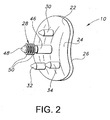
- the glenoid component 10 includes a body portion 22 having a first generally convex surface 24 and a second generally concave surface 26.
- the convex surface 24 is configured to abut or otherwise contact the glenoid surface 12 of the scapula 14 when the glenoid component 10 is secured thereto.
- the concave surface 26 of the body portion 22 provides a bearing surface for the head portion 20 of the humeral component 16 implanted into the humerus 18.
- the glenoid component also includes the anchor peg (or central peg) 28 and a number of stabilizing pegs 30, 32, 34.
- the anchor peg 28 and the stabilizing pegs 30, 32, 34 are secured to the convex surface 24 of the body portion 22 and extend outwardly therefrom.
- the anchor peg 28 is received into an anchor hole 38 which is drilled or otherwise formed in the glenoid surface 12 of the scapula 14, whereas the stabilizing pegs 30, 32, 34 are received into a number of respective stabilizing holes 40, 42, 44 which are also drilled or otherwise formed in the glenoid surface 12 of the scapula 14.
- the anchor peg 28 includes a bevelled shaft portion 46 that is secured at its proximal end to the convex surface 24.
- the distal end portion of the shaft portion 46 has a conical tip 48 defined therein which is provided as a "lead in” to facilitate insertion of the anchor peg 28 into the anchor hole 38 drilled in the glenoid surface 12 of the scapula 14.
- the distal end portion of the shaft portion 46 also has a number of fins 50 (or flutes) secured thereto.
- the fins 50 extend radially outwardly from the shaft portion 46 of the anchor peg 28 in a substantially perpendicular direction relative to the shaft portion 46 such that the outer diameter of each of the fins 50 is greater than the outer diameter of the shaft portion 46.
- Each of the fins 50 preferably extends continuously around the entire outer periphery of the shaft portion 46, although the fins 50 may alternatively be embodied as a series of individual flange sections that line substantially all of the outer periphery of the shaft portion 46.
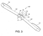
- a bone graft applicator (or instrument) 60 is provided as shown in FIGS. 3 and 4 .
- the bone graft applicator 60 includes a pair of arms 62, 64. The pair of arms 62, 64 are coupled via a linking mechanism 66.
- the linking mechanism 66 is a ring 68.
- the ring 68 includes a recess 70 that is sized and shaped to receive the fins 50 of the glenoid component 10.
- the linking mechanism 66 is sized and shaped to slide over and around the portion of the implant that is to receive the bone graft.
- the linking mechanism 66 may extend only partially around the portion of the implant that is to receive the bone graft.
- the linking mechanism 66 may not be able to slide over the portion of the implant, but may still extend partially around that portion.
- each of the arms 62, 64 includes a handle 72, 74.
- the handles 72, 74 allow the user to grasp the applicator 60.
- the handles 72, 74 may not be included and the user may grasp the arms 62, 64.
- the arms 62, 64 are coupled to a bone graft receptacle 75.
- the bone graft receptacle 75 includes a pair of cavities 76, 78.
- the cavities 76, 78 are coupled to and adjacent to the linking mechanism 66. They are each linked to the linking mechanism 66 via a hinge 79.
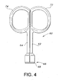
- the hinge allows the cavities 76, 78 (and thus the arms 62, 64) to open and close as shown in FIGS. 3 and 4 .
- the hinge 79 allows the cavities 76, 78 (and thus arms 62, 64) to open to a large angle ⁇ (defined as the angle between the two arms 62, 64).
- the angle ⁇ is between about 100 and about 180°. Preferably, the angle ⁇ is between about 170 and about 180°.
- the cavities 76, 78 are easier to fill with the bone graft.
- the cavities 76, 78 are sized and shaped to receive the bone graft.
- the cavities 76, 78 create a single cavity that is sized and shaped to receive the anchor peg 28 (as will be shown in FIG. 7 below).
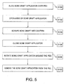
- FIGS. 5 to 8 show steps in a method of using the bone graft applicator 60.
- the bone graft applicator 60 is slid over the anchor peg 28, which may be sitting on a table with the articular surface down and anchor peg 28 up.
- the arms 62, 64 of the applicator 60 are then opened as shown in FIG. 6 at step s102, exposing the fins 50.
- the applicator may be in an open position prior to being slid over the anchor peg.
- the ring 68 slides over (and thus extends around) the anchor peg 28 and fins 50.
- the recess 70 (which is in this embodiment, a circular opening) is slid over the anchor peg 28.
- the bone graft also known as bone paste
- the bone graft should be placed into both cavities 76, 78.
- an instrument 80 holds bone graft 82.
- a scraper 84 is used to scrape the bone graft 82 out of the instrument 80 and into the cavities 76, 78 of the bone graft applicator 60.
- Other tools or methods for applying the bone graft to the cavities 76, 78 may be used in other devices.
- the bone graft applicator 60 is closed over the anchor peg 28 and its fins 50 (shown in FIG. 7 ).
- the two cavities 76, 78 surround the anchor peg 28 and apply the bone graft 82 in between the fins 50.
- the bone graft applicator 60 applies the bone graft equally to both sides simultaneously.
- the two cavities 76, 78 surround the peg at the same time, are perpendicular to the ground, and are equally affected by the effects of gravity, thereby applying the bone graft equally (and simultaneously) around the peg 28.
- the bone graft applicator is then rotated about the anchor peg 28 in the direction shown by arrows 86 in FIG.
- step s110 bone graft 82 fills in the space between the fins 50. Removal of the bone graft applicator is easy since the bone graft applicator 60 is kept closed. Also, since the cavities 76, 78 are closed, any bone graft 82 that is not affixed to the fins 50 is less likely to spill out of the applicator 60. Furthermore, removal along the axis as indicated by the arrow 88 compresses the bone graft 82 into the fins 50 and prevents migration of the bone graft 82 out of the sides of the fins 50.
- FIG. 9 shows another bone graft applicator 110.
- This bone graft applicator 110 includes a pair of arms 112, 114.
- the pair of arms 112, 114 are coupled via a linking mechanism 116.
- the linking mechanism 116 is a pair of rods 118, 120 and a u-shaped wall 124 and an arcuate wall 126.
- the pair of rods 118, 120 extends from one arm 112, 114 into a recess on the other arm 112, 114 (not shown).
- the u-shaped wall 124 and arcuate wall 126 also define the bone graft receptacle 125.
- the bone graft receptacle includes a shaped cavity 122.
- the arm 112 also includes two channels 130, 132 that receive the ends of the u-shaped wall 124.
- the user will place the anchor peg 28 ( FIGS. 1 and 2 ) into the applicator 110.
- the two arms 112, 114 are slid together, causing the ends of the u-shaped wall 124 to slide into the channels 130, 132 and decrease the size of the shaped cavity 122.
- the bone graft is then forced into the fins 50 as the arcuate wall 126 comes closer to the end of the u-shaped wall 124.
- the bone-shaped cavity is then sized and shaped to abut the fins 50 on the anchor peg 28 and to apply the bone graft into the fins 50.
- the arms 112, 114 include handles 134, 136. In other devices, there may not be handles, and the user may just grasp the arms.
- the applicators 60, 110 may be made of stainless steel. In other embodiments, the applicators 60, 110 may be made of plastic. Other materials may also be used. As shown in the embodiments of FIGS. 1 to 4 and 6 to 8 , each of the cavities 76, 78 and each of the arms 62, 64, 112 and 114 are a single piece. However, in other embodiments, the cavity and the arms may be separate pieces and may be coupled using any known method.
- the bone graft applicator may also be used to apply bone graft to pegs located on knee implants, such as a patellar component, a femoral component, or a tibial component.
- the linking mechanism of the bone graft applicator should include a recess large enough to be able to extend around the peg.
- the cavities of such a bone graft applicator would be sized and shaped to accommodate peg of the implant.
- the applicator of the present invention may also be used on other orthopaedic components such as acetabular hip cups, cement plugs, or other pegged implants.
- the pegs of the implants may not be finned (in other words, do not include fins). In these cases, if the peg includes a porous coating, the bone graft would be able to stick to the porous coating.
- the invention also provides a bone graft applicator for applying bone graft to an orthopaedic implant, the bone graft applicator comprising:
- the bone graft receptacle includes a pair of cavities, one of the pair of cavities coupled to one of the pair of arms and the other of the pair of cavities coupled to the other of the pair of arms, and in which each of the pair of cavities is preferably linked to the linking mechanism via a hinge.
- the linking mechanism is a ring defining a recess, and in which the recess is preferably sized and shaped to fit over the portion of the orthopaedic implant.
- each of the pair of arms includes a handle.
- the linking mechanism includes a u-shaped wall and an arcuate wall.
- the invention also provides a method for applying bone graft to an orthopaedic implant, the method comprising:
- the portion of the orthopaedic implant is a finned peg and sliding the linking mechanism includes sliding the linking mechanism over the peg and the method further includes rotating the bone graft applicator around the peg.
- the method includes opening the arms of the bone graft applicator after the linking mechanism has been slid over the portion of the orthopaedic implant.
- the step of removing the bone graft applicator includes leaving the bone graft applicator in a closed position while removing the bone graft applicator.
- the bone graft receptacle includes a pair of cavities, one of the pair of cavities integrally formed with one of the pair of arms and the other of the cavities integrally formed with the other of the pair of arms.
- the method includes simultaneously closing the pair of cavities around the portion of the orthopaedic implant and in which the pair of cavities is held perpendicular to the ground, such that both cavities equally feel the effect of gravity.
- the invention also provides a kit for applying bone graft, the kit comprising:
- the linking mechanism is sized and shaped to extend around the peg.
Landscapes
- Health & Medical Sciences (AREA)
- Orthopedic Medicine & Surgery (AREA)
- Cardiology (AREA)
- Oral & Maxillofacial Surgery (AREA)
- Transplantation (AREA)
- Engineering & Computer Science (AREA)
- Biomedical Technology (AREA)
- Heart & Thoracic Surgery (AREA)
- Vascular Medicine (AREA)
- Life Sciences & Earth Sciences (AREA)
- Animal Behavior & Ethology (AREA)
- General Health & Medical Sciences (AREA)
- Public Health (AREA)
- Veterinary Medicine (AREA)
- Prostheses (AREA)
Abstract
Description
- The present invention relates generally to an instrument for use in orthopaedic surgery, and more particularly to an instrument for grafting bone on to an orthopaedic implant.
- During the lifetime of a patient, it may be necessary to perform a total shoulder replacement procedure on the patient as a result of, for example, disease or trauma. In a total shoulder replacement procedure, a humeral component having a head portion is utilized to replace the natural head portion of the arm bone or humerus. The humeral component typically has an elongated intramedullary stem that is utilized to secure the humeral component to the patient's humerus. In such a total shoulder replacement procedure, the natural glenoid surface of the scapula is resurfaced or otherwise replaced with a glenoid component that provides a bearing surface for the head portion of the humeral component.
- In response to shortcomings associated with two-piece glenoid component designs, a number of one-piece glenoid components have heretofore been designed. In regard to such one-piece designs, a body portion, having a bearing surface defined therein for receiving the head of the humeral component, has a number of attachment pegs integrally formed therewith. The attachment pegs are advanced and thereafter secured into a corresponding number of holes that are drilled in the glenoid surface of the scapula by use of bone cement. An example of such a one-piece glenoid component that is designed to be secured to the scapula by use of bone cement is disclosed in
US-5032132 . - Certain one-piece glenoid components have been designed to include finned-pegs for example as disclosed in
US-6911047 . The fins act as barbs when the pegs are inserted into holes drilled in the scapula, securing the glenoid component to the scapula. - In some methods of inserting the finned-peg glenoid implant to the scapula, bone graft is inserted between the fins. Adding bone graft aids in the osseointegration of the implant into the scapula. However, there is currently not an instrument offered that places the bone graft on to the implant. Oftentimes, a member of the surgical team will use their gloved hands to apply the bone graft on to the pegs. However, the bone graft will often stick to the user's gloves, making this method of applying bone graft messy and imprecise.
- Therefore, there is a need for an instrument to apply bone graft to a glenoid component and other orthopaedic implant components.
- The invention provides a bone graft applicator for applying bone graft to an orthopaedic implant. The bone graft applicator includes a pair of arms and a bone graft receptacle sized and shaped to be able to receive a portion of the orthopaedic implant within the receptacle. The bone graft receptacle is coupled to each of the pair of arms. The bone graft applicator further includes a linking mechanism, the linking mechanism including a recess sized and shaped to extend at least partially around the portion of the orthopaedic implant, the linking mechanism coupled to the bone graft receptacle.
- The invention also provides a method of applying bone graft to an orthopaedic implant. The method includes using a bone graft applicator including a pair of arms, a bone graft receptacle coupled to the arms, and a linking mechanism coupled to the bone graft receptacle. The linking mechanism is slid over a portion of the orthopaedic implant and bone graft is scraped into the bone graft receptacle. The bone graft receptacle is closed over the portion of the orthopaedic implant. The bone graft applicator is removed from the orthopaedic implant.
- The invention also provides a kit for applying bone graft which includes a glenoid component having a peg and a bone graft applicator. The bone graft applicator is sized and shaped to apply bone graft to the peg of the glenoid component. The bone graft applicator includes a pair of arms, a pair of cavities coupled to the pair of arms, and a linking mechanism coupled to the pair of cavities. The pair of cavities can be in an opened position such that one of the pair of cavities is located at an angle from the other of the pair of cavities and the angle is in the range of about 100° to about 180°.
- The invention is described below by way of example with reference to the accompanying drawings, in which:
-
FIG. 1 is an exploded perspective view that shows a glenoid component positioned between a glenoid surface of a scapula and a humeral component. -
FIG. 2 is a perspective view of the glenoid component ofFIG. 1 . -
FIG. 3 is a perspective view of a bone graft applicator in an open position. -
FIG. 4 is a perspective view of a bone graft applicator ofFIG. 3 in a closed position. -
FIG. 5 is a flow chart illustrating the method of operating the bone graft applicator ofFIG. 3 . -
FIG. 6 is a perspective view of the bone graft applicator ofFIG. 3 and a glenoid component ofFIG. 1 in use. -
FIG. 7 is a perspective view of the bone graft applicator ofFIG. 3 applying bone graft to the glenoid component ofFIG. 1 . -
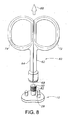
FIG. 8 is a perspective view of the bone graft applicator ofFIG. 3 after it has been removed from the glenoid component ofFIG. 1 . -
FIG. 9 is a perspective view of another bone graft applicator. - Referring to the drawings,
FIG. 1 shows aglenoid component 10 located between aglenoid surface 12 of ascapula 14 and ahumeral component 16. Thehumeral component 16 has been implanted or otherwise secured to ahumerus 18. As discussed below in greater detail, theglenoid component 10 is configured to be secured to theglenoid surface 12 of thescapula 14 without the use of bone cement on an anchor peg 28 (discussed below) in order to replace thenatural glenoid surface 12 during a total shoulder replacement procedure. In such a manner, theglenoid component 10 functions as a bearing surface for receiving a head portion of the humerus 18 (i.e. ahead portion 20 of thehumeral component 16 implanted in the humerus 18). - As shown in
FIGS. 1 and2 , theglenoid component 10 includes abody portion 22 having a first generallyconvex surface 24 and a second generallyconcave surface 26. The convexsurface 24 is configured to abut or otherwise contact theglenoid surface 12 of thescapula 14 when theglenoid component 10 is secured thereto. Theconcave surface 26 of thebody portion 22 provides a bearing surface for thehead portion 20 of thehumeral component 16 implanted into thehumerus 18. - The glenoid component also includes the anchor peg (or central peg) 28 and a number of stabilizing
pegs anchor peg 28 and the stabilizingpegs convex surface 24 of thebody portion 22 and extend outwardly therefrom. As shown inFIG. 1 , theanchor peg 28 is received into ananchor hole 38 which is drilled or otherwise formed in theglenoid surface 12 of thescapula 14, whereas the stabilizingpegs holes glenoid surface 12 of thescapula 14. - The
anchor peg 28 includes a bevelledshaft portion 46 that is secured at its proximal end to theconvex surface 24. The distal end portion of theshaft portion 46 has aconical tip 48 defined therein which is provided as a "lead in" to facilitate insertion of theanchor peg 28 into theanchor hole 38 drilled in theglenoid surface 12 of thescapula 14. - In addition to the
conical tip 48, the distal end portion of theshaft portion 46 also has a number of fins 50 (or flutes) secured thereto. Thefins 50 extend radially outwardly from theshaft portion 46 of theanchor peg 28 in a substantially perpendicular direction relative to theshaft portion 46 such that the outer diameter of each of thefins 50 is greater than the outer diameter of theshaft portion 46. Each of thefins 50 preferably extends continuously around the entire outer periphery of theshaft portion 46, although thefins 50 may alternatively be embodied as a series of individual flange sections that line substantially all of the outer periphery of theshaft portion 46. - As discussed above, some surgeons desire to place bone graft on to the
fins 50 and into the spaces between thefins 50 to aid in the bone integration of the implant. The bone graft may be taken from a number of places. In some circumstances, the bone graft can be taken from drilling theanchor hole 38 of the glenoid. In other circumstances, it can be taken from drilling the resected portion of the humeral head. To aid in this, a bone graft applicator (or instrument) 60 is provided as shown inFIGS. 3 and4 . As shown, thebone graft applicator 60 includes a pair ofarms arms mechanism 66. In this device, the linkingmechanism 66 is aring 68. Thering 68 includes arecess 70 that is sized and shaped to receive thefins 50 of theglenoid component 10. In this device, the linkingmechanism 66 is sized and shaped to slide over and around the portion of the implant that is to receive the bone graft. In other devices, the linkingmechanism 66 may extend only partially around the portion of the implant that is to receive the bone graft. In yet other devices, the linkingmechanism 66 may not be able to slide over the portion of the implant, but may still extend partially around that portion. As shown inFIGS. 3 and4 , each of thearms handle handles applicator 60. In some embodiments, thehandles arms - As shown in
FIG. 3 , thearms bone graft receptacle 75. In the device shown in the drawing, thebone graft receptacle 75 includes a pair ofcavities cavities linking mechanism 66. They are each linked to thelinking mechanism 66 via ahinge 79. The hinge allows thecavities 76, 78 (and thus thearms 62, 64) to open and close as shown inFIGS. 3 and4 . Specifically, thehinge 79 allows thecavities 76, 78 (and thusarms 62, 64) to open to a large angle α (defined as the angle between the twoarms 62, 64). In one embodiment, the angle α is between about 100 and about 180°. Preferably, the angle α is between about 170 and about 180°. By having the arms opened wide, thecavities cavities FIG. 4 , thecavities FIG. 7 below). -
FIGS. 5 to 8 show steps in a method of using thebone graft applicator 60. First, at step s100, thebone graft applicator 60 is slid over theanchor peg 28, which may be sitting on a table with the articular surface down and anchor peg 28 up. Thearms applicator 60 are then opened as shown inFIG. 6 at step s102, exposing thefins 50. In some embodiments, the applicator may be in an open position prior to being slid over the anchor peg. As shown inFIG. 6 , thering 68 slides over (and thus extends around) theanchor peg 28 andfins 50. In other words, the recess 70 (which is in this embodiment, a circular opening) is slid over theanchor peg 28. Next, at step s104, the bone graft (also known as bone paste) is scraped into thecavities cavities FIG. 6 , aninstrument 80 holdsbone graft 82. Ascraper 84 is used to scrape thebone graft 82 out of theinstrument 80 and into thecavities bone graft applicator 60. Other tools or methods for applying the bone graft to thecavities - At step s106, the
bone graft applicator 60 is closed over theanchor peg 28 and its fins 50 (shown inFIG. 7 ). The twocavities anchor peg 28 and apply thebone graft 82 in between thefins 50. In the present embodiment, thebone graft applicator 60 applies the bone graft equally to both sides simultaneously. The twocavities peg 28. The bone graft applicator is then rotated about theanchor peg 28 in the direction shown byarrows 86 inFIG. 7 at step s108 while theanchor peg 28 is held in place (to keep from rotating). The rotation further embeds thebone graft 82 in between thefins 50. With thebone graft applicator 60 still in a closed position, the bone graft applicator is then removed from the anchor peg 28 (step s110). As shown inFIG. 8 ,bone graft 82 fills in the space between thefins 50. Removal of the bone graft applicator is easy since thebone graft applicator 60 is kept closed. Also, since thecavities bone graft 82 that is not affixed to thefins 50 is less likely to spill out of theapplicator 60. Furthermore, removal along the axis as indicated by thearrow 88 compresses thebone graft 82 into thefins 50 and prevents migration of thebone graft 82 out of the sides of thefins 50. -
FIG. 9 shows anotherbone graft applicator 110. Thisbone graft applicator 110 includes a pair ofarms arms linking mechanism 116. In this embodiment, thelinking mechanism 116 is a pair ofrods u-shaped wall 124 and anarcuate wall 126. The pair ofrods arm other arm 112, 114 (not shown). Theu-shaped wall 124 andarcuate wall 126 also define the bone graft receptacle 125. In this embodiment, the bone graft receptacle includes a shapedcavity 122. Thearm 112 also includes twochannels u-shaped wall 124. In use, the user will place the anchor peg 28 (FIGS. 1 and2 ) into theapplicator 110. After the bone graft is poured into thecavity 122, the twoarms u-shaped wall 124 to slide into thechannels cavity 122. The bone graft is then forced into thefins 50 as thearcuate wall 126 comes closer to the end of theu-shaped wall 124. By moving thearms fins 50 on theanchor peg 28 and to apply the bone graft into thefins 50. In the illustrated applicator, thearms handles - In some embodiments, the
applicators applicators FIGS. 1 to 4 and6 to 8 , each of thecavities arms - The above embodiments both describe using the bone graft applicator to apply bone graft to a peg on a glenoid component. However, the bone graft applicator may also be used to apply bone graft to pegs located on knee implants, such as a patellar component, a femoral component, or a tibial component. In each of these cases, the linking mechanism of the bone graft applicator should include a recess large enough to be able to extend around the peg. Also, the cavities of such a bone graft applicator would be sized and shaped to accommodate peg of the implant. The applicator of the present invention may also be used on other orthopaedic components such as acetabular hip cups, cement plugs, or other pegged implants. In some embodiments, the pegs of the implants may not be finned (in other words, do not include fins). In these cases, if the peg includes a porous coating, the bone graft would be able to stick to the porous coating.
- The invention also provides a bone graft applicator for applying bone graft to an orthopaedic implant, the bone graft applicator comprising:
- a pair of arms,
- a bone graft receptacle sized and shaped to be able to receive a portion of the orthopaedic implant within the receptacle, the bone graft receptacle coupled to each of the pair of arms, and
- a linking mechanism, the linking mechanism including a recess sized and shaped to extend at least partially around the portion of the orthopaedic implant, the linking mechanism coupled to the bone graft receptacle.
- Optionally, the bone graft receptacle includes a pair of cavities, one of the pair of cavities coupled to one of the pair of arms and the other of the pair of cavities coupled to the other of the pair of arms, and in which each of the pair of cavities is preferably linked to the linking mechanism via a hinge.
- Optionally, the linking mechanism is a ring defining a recess, and in which the recess is preferably sized and shaped to fit over the portion of the orthopaedic implant.
- Optionally, each of the pair of arms includes a handle.
- Optionally, the linking mechanism includes a u-shaped wall and an arcuate wall.
- The invention also provides a method for applying bone graft to an orthopaedic implant, the method comprising:
- using a bone graft applicator including a pair of arms, a bone graft receptacle coupled to the arms, and a linking mechanism coupled to the bone graft receptacle,
- sliding the linking mechanism over a portion of the orthopaedic implant,
- scraping bone graft into the bone graft receptacle,
- closing the bone graft receptacle over the portion of the orthopaedic implant, and
- removing one of the bone graft applicator and the orthopaedic implant from the other of the bone graft applicator and the orthopaedic implant.
- Optionally, the portion of the orthopaedic implant is a finned peg and sliding the linking mechanism includes sliding the linking mechanism over the peg and the method further includes rotating the bone graft applicator around the peg.
- Optionally, the method includes opening the arms of the bone graft applicator after the linking mechanism has been slid over the portion of the orthopaedic implant.
- Optionally, the step of removing the bone graft applicator includes leaving the bone graft applicator in a closed position while removing the bone graft applicator.
- Optionally, the bone graft receptacle includes a pair of cavities, one of the pair of cavities integrally formed with one of the pair of arms and the other of the cavities integrally formed with the other of the pair of arms.
- Optionally, the method includes simultaneously closing the pair of cavities around the portion of the orthopaedic implant and in which the pair of cavities is held perpendicular to the ground, such that both cavities equally feel the effect of gravity.
- The invention also provides a kit for applying bone graft, the kit comprising:
- a glenoid component having a peg, and
- a bone graft applicator sized and shaped to apply bone graft to the peg of the glenoid component, the bone graft applicator including a pair of arms, a pair of cavities coupled to the pair of arms, and a linking mechanism coupled to the pair of cavities, in which the pair of cavities such that the pair of cavities can be in an opened position such that one of the pair of cavities is located at an angle from the other of the pair of cavities and the angle is in the range of about 100° to about 180°.
- Optionally:
- (a) the peg has a plurality of fins and the bone graft applicator is sized and shaped to apply bone graft between the plurality of fins, and/or
- (b) the peg includes a porous coating and the bone graft applicator is sized and shaped to apply bone graft into pores of the porous coating.
- Optionally, the linking mechanism is sized and shaped to extend around the peg.
- Optionally:
- (a) the linking mechanism is a ring defining a recess, the recess having a diameter larger than the peg, and/or
- (b) the linking mechanism is a moveable u-shaped wall and an arcuate wall, and/or
- (c) the linking mechanism is coupled to the pair of cavities via hinges.
Claims (8)
- A kit for applying bone graft, the kit comprising a glenoid component having a peg, and a bone graft applicator, which comprises:a pair of arms,a bone graft receptacle sized and shaped to be able to receive the peg of the glenoid component within the receptacle, the bone graft receptacle coupled to each of the pair of arms, anda linking mechanism, the linking mechanism including a recess sized and shaped to extend at least partially around the peg of the glenoid component, the linking mechanism coupled to the bone graft receptacle.
- A kit as claimed in claim 1, in which the bone graft applicator includes a pair of cavities coupled to the pair of arms, and in which the linking mechanism is coupled to the pair of cavities such that the pair of cavities can be in an opened position such that one of the pair of cavities is located at an angle from the other of the pair of cavities and the angle is in the range of about 100° to about 180°.
- A kit as claimed in claim 1, in which the peg has a plurality of fins and the bone graft applicator is sized and shaped to apply bone graft between the plurality of fins.
- A kit as claimed in claim 1, in which the peg includes a porous coating and the bone graft applicator is sized and shaped to apply bone graft into pores of the porous coating.
- A kit as claimed in claim 1, in which the linking mechanism is a ring defining a recess, the recess having a diameter larger than the peg.
- A kit as claimed in claim 1, in which the linking mechanism is a moveable U-shaped wall and an arcuate wall.
- A kit as claimed in claim 1, in which the linking mechanism is coupled to the pair of cavities by means of hinges.
- A kit as claimed in claim 1, in which each of the pair of arms includes a handle.
Applications Claiming Priority (3)
| Application Number | Priority Date | Filing Date | Title |
|---|---|---|---|
| US34532410P | 2010-05-17 | 2010-05-17 | |
| US12/860,487 US8486067B2 (en) | 2010-05-17 | 2010-08-20 | Bone graft applicator |
| EP11164645.1A EP2387975B1 (en) | 2010-05-17 | 2011-05-03 | Bone graft applicator |
Related Parent Applications (2)
| Application Number | Title | Priority Date | Filing Date |
|---|---|---|---|
| EP11164645.1A Division EP2387975B1 (en) | 2010-05-17 | 2011-05-03 | Bone graft applicator |
| EP11164645.1 Division | 2011-05-03 |
Publications (3)
| Publication Number | Publication Date |
|---|---|
| EP2606858A1 true EP2606858A1 (en) | 2013-06-26 |
| EP2606858B1 EP2606858B1 (en) | 2014-10-29 |
| EP2606858B8 EP2606858B8 (en) | 2014-12-17 |
Family
ID=44117682
Family Applications (2)
| Application Number | Title | Priority Date | Filing Date |
|---|---|---|---|
| EP11164645.1A Active EP2387975B1 (en) | 2010-05-17 | 2011-05-03 | Bone graft applicator |
| EP13160457.1A Active EP2606858B8 (en) | 2010-05-17 | 2011-05-03 | Bone graft applicator |
Family Applications Before (1)
| Application Number | Title | Priority Date | Filing Date |
|---|---|---|---|
| EP11164645.1A Active EP2387975B1 (en) | 2010-05-17 | 2011-05-03 | Bone graft applicator |
Country Status (2)
| Country | Link |
|---|---|
| US (2) | US8486067B2 (en) |
| EP (2) | EP2387975B1 (en) |
Families Citing this family (14)
| Publication number | Priority date | Publication date | Assignee | Title |
|---|---|---|---|---|
| US7892288B2 (en) | 2001-08-27 | 2011-02-22 | Zimmer Technology, Inc. | Femoral augments for use with knee joint prosthesis |
| US20030065397A1 (en) | 2001-08-27 | 2003-04-03 | Hanssen Arlen D. | Prosthetic implant support structure |
| FR2932674B1 (en) | 2008-06-20 | 2011-11-18 | Tornier Sa | METHOD FOR MODELING A GLENOIDAL SURFACE OF AN OMOPLATE, DEVICE FOR IMPLANTING A GLENOIDAL COMPONENT OF A SHOULDER PROSTHESIS, AND METHOD FOR MANUFACTURING SUCH COMPOUND |
| EP3068317B1 (en) | 2013-11-13 | 2018-08-22 | Tornier | Shoulder patient specific instrument |
| US20150272741A1 (en) * | 2014-03-26 | 2015-10-01 | Biomet Manufacturing, Llc | Press-fit glenoid with peripheral compression pegs |
| WO2017105815A1 (en) | 2015-12-16 | 2017-06-22 | Tornier, Inc. | Patient specific instruments and methods for joint prosthesis |
| EP3685804A1 (en) | 2016-03-25 | 2020-07-29 | Tornier | Joint prosthesis spacer |
| US10231846B2 (en) | 2016-08-19 | 2019-03-19 | Stryker European Holdings I, Llc | Bone graft delivery loading assembly |
| CN110191691B (en) | 2017-01-20 | 2022-03-22 | 拜欧米特制造有限责任公司 | Modular expansion component |
| US11234721B2 (en) | 2017-07-11 | 2022-02-01 | Howmedica Osteonics Corp. | Guides and instruments for improving accuracy of glenoid implant placement |
| EP3651662B1 (en) | 2017-07-11 | 2025-07-02 | Howmedica Osteonics Corp. | Patient specific humeral cutting guides |
| EP3731783A1 (en) | 2017-12-29 | 2020-11-04 | Tornier, Inc. | Patient specific humeral implant components |
| US12324750B2 (en) * | 2021-03-26 | 2025-06-10 | Arthrex, Inc. | Shield guide assembly |
| EP4554521A4 (en) * | 2022-07-14 | 2026-03-25 | Howmedica Osteonics Corp | Monolithic baseplate |
Citations (6)
| Publication number | Priority date | Publication date | Assignee | Title |
|---|---|---|---|---|
| US5032132A (en) | 1990-01-22 | 1991-07-16 | Boehringer Mannheim Corporation | Glenoid component |
| US20030125811A1 (en) * | 1991-08-12 | 2003-07-03 | Bonutti Peter M. | Method for forming implant containing tissue |
| US20040034362A1 (en) * | 2000-12-21 | 2004-02-19 | Stryker Spine | Bone graft forming guide |
| US20040167617A1 (en) * | 2001-01-26 | 2004-08-26 | Voellmicke John C. | Graft delivery system |
| US6911047B2 (en) | 2000-03-17 | 2005-06-28 | Depuy Orthopaedics, Inc. | Apparatus and method for securing a cementless glenoid component to a glenoid surface of a scapula |
| US20080183297A1 (en) * | 2007-01-30 | 2008-07-31 | Tornier | Method and apparatus for fitting a shoulder prosthesis |
Family Cites Families (2)
| Publication number | Priority date | Publication date | Assignee | Title |
|---|---|---|---|---|
| US5195856A (en) * | 1991-08-29 | 1993-03-23 | Titan Technology, Inc. | Deformable fastening device |
| US6458136B1 (en) | 2000-05-11 | 2002-10-01 | Zimmer, Inc. | Orthopaedic instrument for sizing implant sites and for pressurizing bone cement and a method for using the same |
-
2010
- 2010-08-20 US US12/860,487 patent/US8486067B2/en active Active
-
2011
- 2011-05-03 EP EP11164645.1A patent/EP2387975B1/en active Active
- 2011-05-03 EP EP13160457.1A patent/EP2606858B8/en active Active
-
2013
- 2013-06-14 US US13/917,678 patent/US8814942B2/en active Active
Patent Citations (6)
| Publication number | Priority date | Publication date | Assignee | Title |
|---|---|---|---|---|
| US5032132A (en) | 1990-01-22 | 1991-07-16 | Boehringer Mannheim Corporation | Glenoid component |
| US20030125811A1 (en) * | 1991-08-12 | 2003-07-03 | Bonutti Peter M. | Method for forming implant containing tissue |
| US6911047B2 (en) | 2000-03-17 | 2005-06-28 | Depuy Orthopaedics, Inc. | Apparatus and method for securing a cementless glenoid component to a glenoid surface of a scapula |
| US20040034362A1 (en) * | 2000-12-21 | 2004-02-19 | Stryker Spine | Bone graft forming guide |
| US20040167617A1 (en) * | 2001-01-26 | 2004-08-26 | Voellmicke John C. | Graft delivery system |
| US20080183297A1 (en) * | 2007-01-30 | 2008-07-31 | Tornier | Method and apparatus for fitting a shoulder prosthesis |
Also Published As
| Publication number | Publication date |
|---|---|
| US8814942B2 (en) | 2014-08-26 |
| EP2606858B8 (en) | 2014-12-17 |
| EP2387975A1 (en) | 2011-11-23 |
| EP2387975B1 (en) | 2013-10-23 |
| US20110282403A1 (en) | 2011-11-17 |
| US20130282066A1 (en) | 2013-10-24 |
| EP2606858B1 (en) | 2014-10-29 |
| US8486067B2 (en) | 2013-07-16 |
Similar Documents
| Publication | Publication Date | Title |
|---|---|---|
| EP2387975B1 (en) | Bone graft applicator | |
| US12208015B2 (en) | System and method for implanting a secondary glenoid prosthesis | |
| US12447021B2 (en) | Graft collection and containment system for bone defects | |
| US10517736B2 (en) | Glenoid defect-filling component | |
| US11759335B2 (en) | Engineered sterile cartilage allograft implant plug with sterile, specific instrument kit(s) | |
| AU2013206575B2 (en) | Surgical instrument and method of disassembling a tibial prosthesis | |
| US9248022B2 (en) | Method of implanting a glenoid defect-filling component | |
| JP2022009285A (en) | Orthopedic surgical instrument system for surgically preparing patient's femur | |
| CN102014800A (en) | Partial joint resurfacing implant, instrumentation, and method | |
| CN101152101A (en) | proximal reamer | |
| EP2777635B1 (en) | Surgical instrument | |
| EP1393695B1 (en) | Cemented prosthetic kit | |
| JP2014176692A (en) | Orthopedic knee prosthesis having stem components with varying number of slots |
Legal Events
| Date | Code | Title | Description |
|---|---|---|---|
| AC | Divisional application: reference to earlier application |
Ref document number: 2387975 Country of ref document: EP Kind code of ref document: P |
|
| AK | Designated contracting states |
Kind code of ref document: A1 Designated state(s): AL AT BE BG CH CY CZ DE DK EE ES FI FR GB GR HR HU IE IS IT LI LT LU LV MC MK MT NL NO PL PT RO RS SE SI SK SM TR |
|
| PUAI | Public reference made under article 153(3) epc to a published international application that has entered the european phase |
Free format text: ORIGINAL CODE: 0009012 |
|
| 17P | Request for examination filed |
Effective date: 20131217 |
|
| RBV | Designated contracting states (corrected) |
Designated state(s): AL AT BE BG CH CY CZ DE DK EE ES FI FR GB GR HR HU IE IS IT LI LT LU LV MC MK MT NL NO PL PT RO RS SE SI SK SM TR |
|
| GRAP | Despatch of communication of intention to grant a patent |
Free format text: ORIGINAL CODE: EPIDOSNIGR1 |
|
| INTG | Intention to grant announced |
Effective date: 20140708 |
|
| GRAS | Grant fee paid |
Free format text: ORIGINAL CODE: EPIDOSNIGR3 |
|
| GRAA | (expected) grant |
Free format text: ORIGINAL CODE: 0009210 |
|
| AC | Divisional application: reference to earlier application |
Ref document number: 2387975 Country of ref document: EP Kind code of ref document: P |
|
| AK | Designated contracting states |
Kind code of ref document: B1 Designated state(s): AL AT BE BG CH CY CZ DE DK EE ES FI FR GB GR HR HU IE IS IT LI LT LU LV MC MK MT NL NO PL PT RO RS SE SI SK SM TR |
|
| REG | Reference to a national code |
Ref country code: GB Ref legal event code: FG4D |
|
| REG | Reference to a national code |
Ref country code: CH Ref legal event code: NV Representative=s name: E. BLUM AND CO. AG PATENT- UND MARKENANWAELTE , CH Ref country code: CH Ref legal event code: PUE Owner name: DEPUY SYNTHES PRODUCTS, LLC, US Free format text: FORMER OWNER: DEPUY PRODUCTS, INC., US Ref country code: CH Ref legal event code: EP |
|
| REG | Reference to a national code |
Ref country code: AT Ref legal event code: REF Ref document number: 693184 Country of ref document: AT Kind code of ref document: T Effective date: 20141115 |
|
| RAP2 | Party data changed (patent owner data changed or rights of a patent transferred) |
Owner name: DEPUY SYNTHES PRODUCTS, LLC |
|
| REG | Reference to a national code |
Ref country code: IE Ref legal event code: FG4D |
|
| REG | Reference to a national code |
Ref country code: DE Ref legal event code: R096 Ref document number: 602011011027 Country of ref document: DE Effective date: 20141211 |
|
| REG | Reference to a national code |
Ref country code: AT Ref legal event code: MK05 Ref document number: 693184 Country of ref document: AT Kind code of ref document: T Effective date: 20141029 |
|
| REG | Reference to a national code |
Ref country code: NL Ref legal event code: VDEP Effective date: 20141029 |
|
| REG | Reference to a national code |
Ref country code: LT Ref legal event code: MG4D |
|
| PG25 | Lapsed in a contracting state [announced via postgrant information from national office to epo] |
Ref country code: IS Free format text: LAPSE BECAUSE OF FAILURE TO SUBMIT A TRANSLATION OF THE DESCRIPTION OR TO PAY THE FEE WITHIN THE PRESCRIBED TIME-LIMIT Effective date: 20150228 Ref country code: ES Free format text: LAPSE BECAUSE OF FAILURE TO SUBMIT A TRANSLATION OF THE DESCRIPTION OR TO PAY THE FEE WITHIN THE PRESCRIBED TIME-LIMIT Effective date: 20141029 Ref country code: PT Free format text: LAPSE BECAUSE OF FAILURE TO SUBMIT A TRANSLATION OF THE DESCRIPTION OR TO PAY THE FEE WITHIN THE PRESCRIBED TIME-LIMIT Effective date: 20150302 Ref country code: FI Free format text: LAPSE BECAUSE OF FAILURE TO SUBMIT A TRANSLATION OF THE DESCRIPTION OR TO PAY THE FEE WITHIN THE PRESCRIBED TIME-LIMIT Effective date: 20141029 Ref country code: NL Free format text: LAPSE BECAUSE OF FAILURE TO SUBMIT A TRANSLATION OF THE DESCRIPTION OR TO PAY THE FEE WITHIN THE PRESCRIBED TIME-LIMIT Effective date: 20141029 Ref country code: LT Free format text: LAPSE BECAUSE OF FAILURE TO SUBMIT A TRANSLATION OF THE DESCRIPTION OR TO PAY THE FEE WITHIN THE PRESCRIBED TIME-LIMIT Effective date: 20141029 Ref country code: NO Free format text: LAPSE BECAUSE OF FAILURE TO SUBMIT A TRANSLATION OF THE DESCRIPTION OR TO PAY THE FEE WITHIN THE PRESCRIBED TIME-LIMIT Effective date: 20150129 |
|
| PG25 | Lapsed in a contracting state [announced via postgrant information from national office to epo] |
Ref country code: LV Free format text: LAPSE BECAUSE OF FAILURE TO SUBMIT A TRANSLATION OF THE DESCRIPTION OR TO PAY THE FEE WITHIN THE PRESCRIBED TIME-LIMIT Effective date: 20141029 Ref country code: SE Free format text: LAPSE BECAUSE OF FAILURE TO SUBMIT A TRANSLATION OF THE DESCRIPTION OR TO PAY THE FEE WITHIN THE PRESCRIBED TIME-LIMIT Effective date: 20141029 Ref country code: HR Free format text: LAPSE BECAUSE OF FAILURE TO SUBMIT A TRANSLATION OF THE DESCRIPTION OR TO PAY THE FEE WITHIN THE PRESCRIBED TIME-LIMIT Effective date: 20141029 Ref country code: GR Free format text: LAPSE BECAUSE OF FAILURE TO SUBMIT A TRANSLATION OF THE DESCRIPTION OR TO PAY THE FEE WITHIN THE PRESCRIBED TIME-LIMIT Effective date: 20150130 Ref country code: RS Free format text: LAPSE BECAUSE OF FAILURE TO SUBMIT A TRANSLATION OF THE DESCRIPTION OR TO PAY THE FEE WITHIN THE PRESCRIBED TIME-LIMIT Effective date: 20141029 Ref country code: PL Free format text: LAPSE BECAUSE OF FAILURE TO SUBMIT A TRANSLATION OF THE DESCRIPTION OR TO PAY THE FEE WITHIN THE PRESCRIBED TIME-LIMIT Effective date: 20141029 Ref country code: AT Free format text: LAPSE BECAUSE OF FAILURE TO SUBMIT A TRANSLATION OF THE DESCRIPTION OR TO PAY THE FEE WITHIN THE PRESCRIBED TIME-LIMIT Effective date: 20141029 Ref country code: CY Free format text: LAPSE BECAUSE OF FAILURE TO SUBMIT A TRANSLATION OF THE DESCRIPTION OR TO PAY THE FEE WITHIN THE PRESCRIBED TIME-LIMIT Effective date: 20141029 |
|
| REG | Reference to a national code |
Ref country code: DE Ref legal event code: R097 Ref document number: 602011011027 Country of ref document: DE |
|
| PG25 | Lapsed in a contracting state [announced via postgrant information from national office to epo] |
Ref country code: DK Free format text: LAPSE BECAUSE OF FAILURE TO SUBMIT A TRANSLATION OF THE DESCRIPTION OR TO PAY THE FEE WITHIN THE PRESCRIBED TIME-LIMIT Effective date: 20141029 Ref country code: RO Free format text: LAPSE BECAUSE OF FAILURE TO SUBMIT A TRANSLATION OF THE DESCRIPTION OR TO PAY THE FEE WITHIN THE PRESCRIBED TIME-LIMIT Effective date: 20141029 Ref country code: EE Free format text: LAPSE BECAUSE OF FAILURE TO SUBMIT A TRANSLATION OF THE DESCRIPTION OR TO PAY THE FEE WITHIN THE PRESCRIBED TIME-LIMIT Effective date: 20141029 Ref country code: SK Free format text: LAPSE BECAUSE OF FAILURE TO SUBMIT A TRANSLATION OF THE DESCRIPTION OR TO PAY THE FEE WITHIN THE PRESCRIBED TIME-LIMIT Effective date: 20141029 Ref country code: CZ Free format text: LAPSE BECAUSE OF FAILURE TO SUBMIT A TRANSLATION OF THE DESCRIPTION OR TO PAY THE FEE WITHIN THE PRESCRIBED TIME-LIMIT Effective date: 20141029 |
|
| PG25 | Lapsed in a contracting state [announced via postgrant information from national office to epo] |
Ref country code: IT Free format text: LAPSE BECAUSE OF FAILURE TO SUBMIT A TRANSLATION OF THE DESCRIPTION OR TO PAY THE FEE WITHIN THE PRESCRIBED TIME-LIMIT Effective date: 20141029 |
|
| PLBE | No opposition filed within time limit |
Free format text: ORIGINAL CODE: 0009261 |
|
| STAA | Information on the status of an ep patent application or granted ep patent |
Free format text: STATUS: NO OPPOSITION FILED WITHIN TIME LIMIT |
|
| 26N | No opposition filed |
Effective date: 20150730 |
|
| PG25 | Lapsed in a contracting state [announced via postgrant information from national office to epo] |
Ref country code: LU Free format text: LAPSE BECAUSE OF FAILURE TO SUBMIT A TRANSLATION OF THE DESCRIPTION OR TO PAY THE FEE WITHIN THE PRESCRIBED TIME-LIMIT Effective date: 20150503 Ref country code: MC Free format text: LAPSE BECAUSE OF FAILURE TO SUBMIT A TRANSLATION OF THE DESCRIPTION OR TO PAY THE FEE WITHIN THE PRESCRIBED TIME-LIMIT Effective date: 20141029 |
|
| PG25 | Lapsed in a contracting state [announced via postgrant information from national office to epo] |
Ref country code: SI Free format text: LAPSE BECAUSE OF FAILURE TO SUBMIT A TRANSLATION OF THE DESCRIPTION OR TO PAY THE FEE WITHIN THE PRESCRIBED TIME-LIMIT Effective date: 20141029 |
|
| REG | Reference to a national code |
Ref country code: FR Ref legal event code: PLFP Year of fee payment: 6 |
|
| PG25 | Lapsed in a contracting state [announced via postgrant information from national office to epo] |
Ref country code: MT Free format text: LAPSE BECAUSE OF FAILURE TO SUBMIT A TRANSLATION OF THE DESCRIPTION OR TO PAY THE FEE WITHIN THE PRESCRIBED TIME-LIMIT Effective date: 20141029 |
|
| REG | Reference to a national code |
Ref country code: FR Ref legal event code: PLFP Year of fee payment: 7 |
|
| PG25 | Lapsed in a contracting state [announced via postgrant information from national office to epo] |
Ref country code: HU Free format text: LAPSE BECAUSE OF FAILURE TO SUBMIT A TRANSLATION OF THE DESCRIPTION OR TO PAY THE FEE WITHIN THE PRESCRIBED TIME-LIMIT; INVALID AB INITIO Effective date: 20110503 Ref country code: SM Free format text: LAPSE BECAUSE OF FAILURE TO SUBMIT A TRANSLATION OF THE DESCRIPTION OR TO PAY THE FEE WITHIN THE PRESCRIBED TIME-LIMIT Effective date: 20141029 Ref country code: BG Free format text: LAPSE BECAUSE OF FAILURE TO SUBMIT A TRANSLATION OF THE DESCRIPTION OR TO PAY THE FEE WITHIN THE PRESCRIBED TIME-LIMIT Effective date: 20141029 |
|
| PG25 | Lapsed in a contracting state [announced via postgrant information from national office to epo] |
Ref country code: TR Free format text: LAPSE BECAUSE OF FAILURE TO SUBMIT A TRANSLATION OF THE DESCRIPTION OR TO PAY THE FEE WITHIN THE PRESCRIBED TIME-LIMIT Effective date: 20141029 |
|
| PG25 | Lapsed in a contracting state [announced via postgrant information from national office to epo] |
Ref country code: BE Free format text: LAPSE BECAUSE OF FAILURE TO SUBMIT A TRANSLATION OF THE DESCRIPTION OR TO PAY THE FEE WITHIN THE PRESCRIBED TIME-LIMIT Effective date: 20141029 |
|
| REG | Reference to a national code |
Ref country code: FR Ref legal event code: PLFP Year of fee payment: 8 |
|
| PG25 | Lapsed in a contracting state [announced via postgrant information from national office to epo] |
Ref country code: MK Free format text: LAPSE BECAUSE OF FAILURE TO SUBMIT A TRANSLATION OF THE DESCRIPTION OR TO PAY THE FEE WITHIN THE PRESCRIBED TIME-LIMIT Effective date: 20141029 |
|
| PG25 | Lapsed in a contracting state [announced via postgrant information from national office to epo] |
Ref country code: AL Free format text: LAPSE BECAUSE OF FAILURE TO SUBMIT A TRANSLATION OF THE DESCRIPTION OR TO PAY THE FEE WITHIN THE PRESCRIBED TIME-LIMIT Effective date: 20141029 |
|
| REG | Reference to a national code |
Ref country code: FR Ref legal event code: PLFP Year of fee payment: 13 |
|
| PGFP | Annual fee paid to national office [announced via postgrant information from national office to epo] |
Ref country code: DE Payment date: 20250402 Year of fee payment: 15 |
|
| PGFP | Annual fee paid to national office [announced via postgrant information from national office to epo] |
Ref country code: FR Payment date: 20250401 Year of fee payment: 15 |
|
| PGFP | Annual fee paid to national office [announced via postgrant information from national office to epo] |
Ref country code: CH Payment date: 20250601 Year of fee payment: 15 |
|
| PGFP | Annual fee paid to national office [announced via postgrant information from national office to epo] |
Ref country code: IE Payment date: 20250402 Year of fee payment: 15 |
|
| PGFP | Annual fee paid to national office [announced via postgrant information from national office to epo] |
Ref country code: GB Payment date: 20260324 Year of fee payment: 16 |