EP2606765A1 - A partition adapted for separating a cooktop from a underlying drawer - Google Patents
A partition adapted for separating a cooktop from a underlying drawer Download PDFInfo
- Publication number
- EP2606765A1 EP2606765A1 EP12194950.7A EP12194950A EP2606765A1 EP 2606765 A1 EP2606765 A1 EP 2606765A1 EP 12194950 A EP12194950 A EP 12194950A EP 2606765 A1 EP2606765 A1 EP 2606765A1
- Authority
- EP
- European Patent Office
- Prior art keywords
- cabinet
- partition
- portions
- compartment
- cooktop
- Prior art date
- Legal status (The legal status is an assumption and is not a legal conclusion. Google has not performed a legal analysis and makes no representation as to the accuracy of the status listed.)
- Granted
Links
Images


Classifications
-
- A—HUMAN NECESSITIES
- A47—FURNITURE; DOMESTIC ARTICLES OR APPLIANCES; COFFEE MILLS; SPICE MILLS; SUCTION CLEANERS IN GENERAL
- A47B—TABLES; DESKS; OFFICE FURNITURE; CABINETS; DRAWERS; GENERAL DETAILS OF FURNITURE
- A47B77/00—Kitchen cabinets
- A47B77/04—Provision for particular uses of compartments or other parts ; Compartments moving up and down, revolving parts
- A47B77/08—Provision for particular uses of compartments or other parts ; Compartments moving up and down, revolving parts for incorporating apparatus operated by power, including water power; for incorporating apparatus for cooking, cooling, or laundry purposes
-
- F—MECHANICAL ENGINEERING; LIGHTING; HEATING; WEAPONS; BLASTING
- F24—HEATING; RANGES; VENTILATING
- F24C—DOMESTIC STOVES OR RANGES ; DETAILS OF DOMESTIC STOVES OR RANGES, OF GENERAL APPLICATION
- F24C15/00—Details
- F24C15/34—Elements and arrangements for heat storage or insulation
Definitions
- the object of the present invention is a partition adapted to separate a cooktop from a underlying drawer, according to the preamble of the main claim.
- cooktops are usually placed in the upper part of a cabinet. Precisely because of their function, said tops generate heat that is transferred also into the underlying part and then inside the above mentioned cabinet.
- the purpose of the present invention is to provide a partition to be used below a cooktop and adapted to allow the positioning of objects on shelves or within a drawer arranged in a position below said cooktop, which is universally usable with different sized cabinets and on cooktops of different sizes.
- Another object is to provide an universally usable partition that allows the cabinet manufacturer to reduce the costs of their products and the amount of partitions stocked in warehouse.
- a cabinet is generally denoted by 1 and comprises opposing side walls 2 and 3, a rear wall 4, a bottom 5, and has a front face 6, open. Above the cabinet 1, a cooktop 10 is placed (shown only schematically).
- a partition 11 is adapted to separate said top from the interior compartment 12 of the cabinet 1, said partition having adjustable dimensions.
- the partition 11 comprises first side portions 13, 14 adapted to be fixed, by way of screws 15, to the opposite walls 2 and 3 of the cabinet 1.
- said walls have holes 17 arranged at different heights required to hold the partition 11 in different positions with respect to the cooktop as well as to support shelves or components 15 of a drawer 16 located under the partition 1.
- the side portions 13, 14 each presents a substantially L-shape structure with an edge part 18 adapted to be fixed to the corresponding wall 2 and 3 of cabinet 1.
- Said wall forms a substantially right angle with a part 19 protruding from the abovementioned wall 2, 3 of the compartment 12e positioned substantially on a plane orthogonal to the walls 2 and 3.
- a central portion 20 of the partition 11 is adapted to be arranged (preferably with stiffening ribs 27); the portion 20 overlaps the portions 13, 14 in a differentiated manner according to the distance existing between the lateral walls 3 and 4 of the cabinet 1 as the portion 20 has dimensions such as to overlap, however, the portions 13 and 14, whatever the distance between the parts 2 and 3 may be.
- This allows the partition 11 to adapt to different dimensions of the cabinet 1, where dimensions denote the distance between the walls 3 and 4 of the latter, the distance being differentiated according to the different size of the cooktop associated with the cabinet 1.
- Each lateral portion 13, 14 comprises an elongate slot 22 arranged with its axis substantially orthogonal to the plane of the walls 2 and 3.
- a movable tab 26 of the central portion 20 of the partition 11 is adapted to cooperate, said tab 26 being folded towards said side portions and penetrating inside the abovementioned slots 22.
- each portion 13, 14, 20 comprises an end next to the bottom 5 and an end close to the open front face 6 of the cabinet. Respectively, said ends are denoted by 13A, 14A, 20A, 13B, 14B, 20B.
- the ends 13B, 14B, 20B are inclined with respect to the remaining part of the corresponding portions 13, 14, 20 (i.e.
- the end 20B of the portion 20 presents a folded portion below the end itself, shown in Figures 6 and 8 and is denoted by 30, adapted to overlap the ends 13B, 14B of the adjacent side portions 13, 14 so as to receive said ends and contribute to the bond of the portion 20 to the portions 13 and 14 also contribute to the cooperation between the tabs 26 and the slots 22.
- the portion 20 is firmly coupled to the portions 13 and 14 when the partition 1 is assembled. Being the portions 13 and 14 fixed to the side walls 2 and 3 of cabinet 1, the portion 20 results to be firmly fixed to the latter.
- the portions 13, 14, 20 of the partition 11 advantageously and preferably present a layered structure comprising a layer of metal material 20K, preferably aluminum, arranged above the portions 13, 14, 20 or at least above the portion with major surface 20.
- a layer of plastic material 20W preferably polymeric, such as a polyester sheet. Said layers are shown in Figure 4 with reference to the portion 20. In said figure is also shown a separator of the drawer 16, separator denoted by the reference 33.
Landscapes
- Engineering & Computer Science (AREA)
- Life Sciences & Earth Sciences (AREA)
- Sustainable Development (AREA)
- Chemical & Material Sciences (AREA)
- Combustion & Propulsion (AREA)
- Mechanical Engineering (AREA)
- General Engineering & Computer Science (AREA)
- Drawers Of Furniture (AREA)
- Cookers (AREA)
- Baking, Grill, Roasting (AREA)
- Electric Stoves And Ranges (AREA)
Abstract
Description
- The object of the present invention is a partition adapted to separate a cooktop from a underlying drawer, according to the preamble of the main claim.
- As known, cooktops are usually placed in the upper part of a cabinet. Precisely because of their function, said tops generate heat that is transferred also into the underlying part and then inside the above mentioned cabinet.
- It is known to arrange a partition below a cooktop, placed therefore between said top and the underside of the cabinet. Said known partition is fixed to the side walls of the cabinet so as to create below said top an area wherein the heat generated by the top itself cannot penetrate.
- Said known partition, however, has fixed sizes and therefore cannot be used in a generalized way for different sizes of cabinets. In other words, cabinets of different sizes that have associated cooktops of corresponding different sizes (40, 60, 75cm) must provide partitions of different sizes. This results in a greater cost to the cabinet manufacturer as well as the need of having in stock partitions usable for the different dimensions of sold cabinets.
- The purpose of the present invention is to provide a partition to be used below a cooktop and adapted to allow the positioning of objects on shelves or within a drawer arranged in a position below said cooktop, which is universally usable with different sized cabinets and on cooktops of different sizes.
- Another object is to provide an universally usable partition that allows the cabinet manufacturer to reduce the costs of their products and the amount of partitions stocked in warehouse.
- These and other objects which will be apparent to those skilled in the art are attained by a partition in accordance with the accompanying claims.
- For a better understanding of the present invention the following purely indicative, but not limitative drawings are attached, wherein:
-
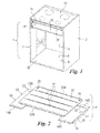
Figure 1 shows, in partial cut-away, a cabinet adapted to support a cooktop and provided with a partition according to the invention; -
Figure 2 shows an exploded perspective view of the partition ofFigure 1 ; -
Figure 3 shows a perspective view of a detail of the partition ofFigure 1 ; -
Figure 4 shows a partial sectional view of the partition offigure 1 ; -
Figure 5 shows a partial perspective view of the partition ofFigure 1 during assembly; and -
Figure 6 shows a longitudinal sectional view of the partition ofFigure 1 ; and -
Figures 7 and 8 show, respectively, enlarged, the parts denoted by A and B inFigure 6 . - With reference to the above figures, a cabinet is generally denoted by 1 and comprises
opposing side walls front face 6, open. Above thecabinet 1, acooktop 10 is placed (shown only schematically). - According to the invention, below said top 10 a
partition 11 is adapted to separate said top from theinterior compartment 12 of thecabinet 1, said partition having adjustable dimensions. - More particularly, the
partition 11 comprisesfirst side portions screws 15, to theopposite walls cabinet 1. Preferably, said walls have holes 17 arranged at different heights required to hold thepartition 11 in different positions with respect to the cooktop as well as to support shelves orcomponents 15 of adrawer 16 located under thepartition 1. - The
side portions edge part 18 adapted to be fixed to thecorresponding wall cabinet 1. Said wall forms a substantially right angle with apart 19 protruding from theabovementioned wall walls - On the
parts 19 of theportions 13, 14 acentral portion 20 of thepartition 11 is adapted to be arranged (preferably with stiffening ribs 27); theportion 20 overlaps theportions lateral walls 3 and 4 of thecabinet 1 as theportion 20 has dimensions such as to overlap, however, theportions parts partition 11 to adapt to different dimensions of thecabinet 1, where dimensions denote the distance between thewalls 3 and 4 of the latter, the distance being differentiated according to the different size of the cooktop associated with thecabinet 1. - Each
lateral portion elongate slot 22 arranged with its axis substantially orthogonal to the plane of thewalls movable tab 26 of thecentral portion 20 of the partition 11 (seeFigures 6 and 7 ) is adapted to cooperate, saidtab 26 being folded towards said side portions and penetrating inside theabovementioned slots 22. - In addition, each
portion open front face 6 of the cabinet. Respectively, said ends are denoted by 13A, 14A, 20A, 13B, 14B, 20B. Theends corresponding portions parts 19 of the side portions and to said 20 which lie on a plane orthogonal to thewalls end 20B of theportion 20, in particular, presents a folded portion below the end itself, shown inFigures 6 and 8 and is denoted by 30, adapted to overlap theends adjacent side portions portion 20 to theportions tabs 26 and theslots 22. - Thanks to said ends overlapping and to the cooperation between tabs and slots, the
portion 20 is firmly coupled to theportions partition 1 is assembled. Being theportions side walls cabinet 1, theportion 20 results to be firmly fixed to the latter. - In this way, a
partition 11 between thecooktop 10 and theinternal compartment 12 of the abovementioned cabinet is created, the partition preventing the heat from being transferred from the top to said compartment and allowing the arrangement in the latter of a drawer 16 (arranged below the partition) and/or shelves designed to hold objects inside said compartment. In order to avoid the transfer of heat in thecompartment 12, theportions partition 11 advantageously and preferably present a layered structure comprising a layer ofmetal material 20K, preferably aluminum, arranged above theportions major surface 20. Below saidmetal layer 20K there is a layer ofplastic material 20W, preferably polymeric, such as a polyester sheet. Said layers are shown inFigure 4 with reference to theportion 20. In said figure is also shown a separator of thedrawer 16, separator denoted by thereference 33. - Thanks to the invention it is possible to obtain a partition adapted to allow the use of an internal compartment of a cabinet on the upper part of which a cooktop that closes the compartment itself is placed. The above, independently of the size of the compartment i.e. of the distance between the
side walls cabinet 1. - This is obtained thanks to the use of a partition having separate parts between each other, but firmly coupled when in use, and adapted to be arranged relatively to one another so as to completely close the compartment below the cooktop. An embodiment of the invention has been described wherein the
partition 11 comprises three portions separated from each other. Obviously, there are other possible alternatives such as those that include a partition having only two portions coupled to each other, or two portions telescopically coupled to each other and fixed to theside walls cabinet 1. Also these embodiments are to be considered as comprised within the scope of the following claims.
Claims (6)
- A partition adapted for separating a cooktop (10) placed on a cabinet, from an inner compartment (12) of said cabinet (1), said compartment (12) being delimited by side walls (2, 3), by a bottom (5) and by a rear wall (4), the compartment being independently open (at 6) and having the cooktop (10) on top of it, said compartment being adapted to contain objects placed in a drawer (16) or shelves fixed to the side walls (2, 3) thereof, characterized in that it comprises at least two portions (13, 14, 20), movable relative to each other in a direction orthogonal to the side walls (2, 3) of the cabinet (1), adapted to be fixed to said walls, said portions (13, 14, 20) being relatively coupled in a position which is according to the distance of said side walls (2, 3) and such as to completely divide the cooktop (10) from the underlying compartment (12) of the cabinet (1).
- The partition as claimed in claim 1, characterized n that it comprises three separate portions (13, 14, 20), two side portions (13, 14) being fixed to the walls (2, 3) of the cabinet (1), the third portion being coupled to said two portions and being arranged on the latter in a position such as to connect them and to completely divide the cooking compartment (10) from the underlying compartment (12).
- The partition as claimed in claim 2, characterized in that the side portions (13, 14) have a substantially L-shaped conformation, said portions having an edge (18) adapted to be fixed to a corresponding side wall (2, 3) of the cabinet (1) and a part (19) positioned perpendicular to said edge (18) and projecting from the corresponding wall.
- The partition as claimed in claim 2, characterized in that the side portions (13, 14) have elongated slots (22) adapted to cooperate with tabs (26) projecting from the portion (20) that overlaps said side portions (13, 14).
- The partition as claimed in claim 2, characterized in that each portion (13, 14, 20) has an edge (13B, 14B, 20B) facing the opening (6) of the compartment (12) of the cabinet (1), said edge being inclined with respect to the remaining part of the corresponding portion placed on a plane orthogonal to the side walls (2, 3) of said cabinet (1), the inclined edge (20B) of the portion (20) adapted to overlap the side portions (13, 14) having a folded part (30) adapted to receive the corresponding inclined edges (13B, 14B) of said side portions (13, 14).
- The partition as claimed in claim 1, characterized in that it comprises two portions telescopically coupled together.
Applications Claiming Priority (1)
| Application Number | Priority Date | Filing Date | Title |
|---|---|---|---|
| IT002378A ITMI20112378A1 (en) | 2011-12-23 | 2011-12-23 | DIVISION ACTING TO SEPARATE A COOKING PLAN BY AN UNDERLYING DRAWER |
Publications (2)
| Publication Number | Publication Date |
|---|---|
| EP2606765A1 true EP2606765A1 (en) | 2013-06-26 |
| EP2606765B1 EP2606765B1 (en) | 2019-04-03 |
Family
ID=45757090
Family Applications (1)
| Application Number | Title | Priority Date | Filing Date |
|---|---|---|---|
| EP12194950.7A Active EP2606765B1 (en) | 2011-12-23 | 2012-11-30 | A partition adapted for separating a cooktop from a underlying drawer |
Country Status (3)
| Country | Link |
|---|---|
| US (1) | US9072374B2 (en) |
| EP (1) | EP2606765B1 (en) |
| IT (1) | ITMI20112378A1 (en) |
Families Citing this family (2)
| Publication number | Priority date | Publication date | Assignee | Title |
|---|---|---|---|---|
| US10098461B2 (en) * | 2015-06-11 | 2018-10-16 | K-Bloc, Llc | Apparatus and method for mounting an under-cabinet storage system |
| US10244863B2 (en) * | 2016-09-19 | 2019-04-02 | James Daniel Grappe | Adjustable shelf |
Citations (3)
| Publication number | Priority date | Publication date | Assignee | Title |
|---|---|---|---|---|
| JPH11266937A (en) * | 1998-03-25 | 1999-10-05 | Okamura Corp | Extending/contracting type shelf device |
| JP2009273636A (en) * | 2008-05-14 | 2009-11-26 | Panasonic Corp | Heat shielding body of kitchen cabinet |
| JP2009300025A (en) * | 2008-06-16 | 2009-12-24 | Panasonic Corp | Built-in type heating cooker |
Family Cites Families (17)
| Publication number | Priority date | Publication date | Assignee | Title |
|---|---|---|---|---|
| US1069411A (en) * | 1912-12-18 | 1913-08-05 | Harvey Greene | Adjustable receptacle for window-sills. |
| US2266274A (en) * | 1939-01-19 | 1941-12-16 | Henry L Schroeder | Adjustable shelf |
| US2349541A (en) * | 1940-05-23 | 1944-05-23 | Genevieve M Earle | Cabinet structure |
| US2393879A (en) * | 1941-09-30 | 1946-01-29 | Westinghouse Electric Corp | Heating apparatus |
| US4155312A (en) * | 1978-01-12 | 1979-05-22 | Thorkildson Joel B | Extendable shelf |
| US4193650A (en) * | 1978-07-19 | 1980-03-18 | Zero-Max Industries, Inc. | Adjustable shelf device |
| US4540222A (en) * | 1983-02-28 | 1985-09-10 | Burrell Alfred A | Cabinet structure for storing, displaying and indexing |
| IT235741Y1 (en) * | 1995-12-18 | 2000-07-12 | Tomat Dany Severino | PORTABLE KITCHEN |
| US5795041A (en) * | 1996-04-15 | 1998-08-18 | Bush Industries, Inc. | Home theater bridge |
| US6283563B1 (en) * | 2000-02-16 | 2001-09-04 | Sauder Woodworking Co. | Furniture unit |
| US6293272B1 (en) * | 2000-03-25 | 2001-09-25 | Uwe Harneit | Portable cabinet for an outdoor gas grill |
| US6349715B1 (en) * | 2000-11-10 | 2002-02-26 | Mcbroom Douglas C. | Mobile cooking device |
| US6877826B2 (en) * | 2002-04-23 | 2005-04-12 | George W. Wood | Locker shelf assembly with slideable drawer |
| US7040724B2 (en) * | 2003-03-21 | 2006-05-09 | Sligh Furniture Co. | Expandable home entertainment cabinet |
| US7441846B2 (en) * | 2004-07-02 | 2008-10-28 | Chris Lupo | Expandable home television cart |
| WO2008147996A1 (en) * | 2007-05-25 | 2008-12-04 | Herman Miller, Inc. | Office organization unit and system |
| US7987799B2 (en) * | 2007-06-12 | 2011-08-02 | Hoffman Enclosures, Inc. | Adjustable shelf |
-
2011
- 2011-12-23 IT IT002378A patent/ITMI20112378A1/en unknown
-
2012
- 2012-11-30 EP EP12194950.7A patent/EP2606765B1/en active Active
- 2012-12-21 US US13/723,246 patent/US9072374B2/en not_active Expired - Fee Related
Patent Citations (3)
| Publication number | Priority date | Publication date | Assignee | Title |
|---|---|---|---|---|
| JPH11266937A (en) * | 1998-03-25 | 1999-10-05 | Okamura Corp | Extending/contracting type shelf device |
| JP2009273636A (en) * | 2008-05-14 | 2009-11-26 | Panasonic Corp | Heat shielding body of kitchen cabinet |
| JP2009300025A (en) * | 2008-06-16 | 2009-12-24 | Panasonic Corp | Built-in type heating cooker |
Also Published As
| Publication number | Publication date |
|---|---|
| US9072374B2 (en) | 2015-07-07 |
| ITMI20112378A1 (en) | 2013-06-24 |
| EP2606765B1 (en) | 2019-04-03 |
| US20130162129A1 (en) | 2013-06-27 |
Similar Documents
| Publication | Publication Date | Title |
|---|---|---|
| US7987799B2 (en) | Adjustable shelf | |
| US7530845B1 (en) | Connector EMI shielding structure | |
| EP2438835B1 (en) | Reinforcement device for slide assembly | |
| DE102009002059B4 (en) | Refrigerating appliance, in particular household refrigerating appliance, and storage arrangement therefor | |
| USD915829S1 (en) | Food serving trays | |
| US8650901B2 (en) | Tray as well as refrigerator unit and/or freezer unit having at least one tray | |
| EP2606765A1 (en) | A partition adapted for separating a cooktop from a underlying drawer | |
| US10165895B1 (en) | Disposable insert oven grate system | |
| US8522966B1 (en) | Beverage carrying assembly | |
| KR101987449B1 (en) | Cake packing box with base plate | |
| USD923668S1 (en) | Set of food containers with a tray for a refrigerator | |
| JP2006341002A (en) | Cover panel structure and kitchen | |
| RU2448629C2 (en) | Racking construction | |
| JP6455049B2 (en) | Kitchen floor cabinets | |
| USD869527S1 (en) | Side panel for high capacity dispensing unit | |
| KR101869557B1 (en) | Cabinet | |
| US5775789A (en) | Universal container slide for a reach-in cabinet | |
| USD1008987S1 (en) | Inverter panel | |
| JP7444578B2 (en) | Support structure, fixtures and installation method | |
| EP2390584B1 (en) | Oven cabinet | |
| KR101869559B1 (en) | Cabinet | |
| USD868859S1 (en) | Side panel for high capacity dispensing unit | |
| USD868858S1 (en) | Side panel for high capacity dispensing unit | |
| WO2011147531A1 (en) | A casing for a domestic appliance, in particular a domestic cooking oven | |
| WO2021144557A1 (en) | An oven liner device |
Legal Events
| Date | Code | Title | Description |
|---|---|---|---|
| AK | Designated contracting states |
Kind code of ref document: A1 Designated state(s): AL AT BE BG CH CY CZ DE DK EE ES FI FR GB GR HR HU IE IS IT LI LT LU LV MC MK MT NL NO PL PT RO RS SE SI SK SM TR |
|
| AX | Request for extension of the european patent |
Extension state: BA ME |
|
| PUAI | Public reference made under article 153(3) epc to a published international application that has entered the european phase |
Free format text: ORIGINAL CODE: 0009012 |
|
| 17P | Request for examination filed |
Effective date: 20131217 |
|
| RBV | Designated contracting states (corrected) |
Designated state(s): AL AT BE BG CH CY CZ DE DK EE ES FI FR GB GR HR HU IE IS IT LI LT LU LV MC MK MT NL NO PL PT RO RS SE SI SK SM TR |
|
| 17Q | First examination report despatched |
Effective date: 20140904 |
|
| GRAP | Despatch of communication of intention to grant a patent |
Free format text: ORIGINAL CODE: EPIDOSNIGR1 |
|
| STAA | Information on the status of an ep patent application or granted ep patent |
Free format text: STATUS: GRANT OF PATENT IS INTENDED |
|
| RIC1 | Information provided on ipc code assigned before grant |
Ipc: F24C 15/34 20060101ALI20181214BHEP Ipc: A47B 77/08 20060101AFI20181214BHEP |
|
| INTG | Intention to grant announced |
Effective date: 20190114 |
|
| GRAS | Grant fee paid |
Free format text: ORIGINAL CODE: EPIDOSNIGR3 |
|
| GRAA | (expected) grant |
Free format text: ORIGINAL CODE: 0009210 |
|
| STAA | Information on the status of an ep patent application or granted ep patent |
Free format text: STATUS: THE PATENT HAS BEEN GRANTED |
|
| AK | Designated contracting states |
Kind code of ref document: B1 Designated state(s): AL AT BE BG CH CY CZ DE DK EE ES FI FR GB GR HR HU IE IS IT LI LT LU LV MC MK MT NL NO PL PT RO RS SE SI SK SM TR |
|
| REG | Reference to a national code |
Ref country code: GB Ref legal event code: FG4D |
|
| REG | Reference to a national code |
Ref country code: CH Ref legal event code: EP Ref country code: AT Ref legal event code: REF Ref document number: 1114672 Country of ref document: AT Kind code of ref document: T Effective date: 20190415 |
|
| REG | Reference to a national code |
Ref country code: DE Ref legal event code: R096 Ref document number: 602012058513 Country of ref document: DE |
|
| REG | Reference to a national code |
Ref country code: IE Ref legal event code: FG4D |
|
| REG | Reference to a national code |
Ref country code: NL Ref legal event code: MP Effective date: 20190403 |
|
| REG | Reference to a national code |
Ref country code: LT Ref legal event code: MG4D |
|
| REG | Reference to a national code |
Ref country code: AT Ref legal event code: MK05 Ref document number: 1114672 Country of ref document: AT Kind code of ref document: T Effective date: 20190403 |
|
| PG25 | Lapsed in a contracting state [announced via postgrant information from national office to epo] |
Ref country code: NL Free format text: LAPSE BECAUSE OF FAILURE TO SUBMIT A TRANSLATION OF THE DESCRIPTION OR TO PAY THE FEE WITHIN THE PRESCRIBED TIME-LIMIT Effective date: 20190403 |
|
| PG25 | Lapsed in a contracting state [announced via postgrant information from national office to epo] |
Ref country code: LT Free format text: LAPSE BECAUSE OF FAILURE TO SUBMIT A TRANSLATION OF THE DESCRIPTION OR TO PAY THE FEE WITHIN THE PRESCRIBED TIME-LIMIT Effective date: 20190403 Ref country code: SE Free format text: LAPSE BECAUSE OF FAILURE TO SUBMIT A TRANSLATION OF THE DESCRIPTION OR TO PAY THE FEE WITHIN THE PRESCRIBED TIME-LIMIT Effective date: 20190403 Ref country code: FI Free format text: LAPSE BECAUSE OF FAILURE TO SUBMIT A TRANSLATION OF THE DESCRIPTION OR TO PAY THE FEE WITHIN THE PRESCRIBED TIME-LIMIT Effective date: 20190403 Ref country code: CZ Free format text: LAPSE BECAUSE OF FAILURE TO SUBMIT A TRANSLATION OF THE DESCRIPTION OR TO PAY THE FEE WITHIN THE PRESCRIBED TIME-LIMIT Effective date: 20190403 Ref country code: AL Free format text: LAPSE BECAUSE OF FAILURE TO SUBMIT A TRANSLATION OF THE DESCRIPTION OR TO PAY THE FEE WITHIN THE PRESCRIBED TIME-LIMIT Effective date: 20190403 Ref country code: PT Free format text: LAPSE BECAUSE OF FAILURE TO SUBMIT A TRANSLATION OF THE DESCRIPTION OR TO PAY THE FEE WITHIN THE PRESCRIBED TIME-LIMIT Effective date: 20190803 Ref country code: ES Free format text: LAPSE BECAUSE OF FAILURE TO SUBMIT A TRANSLATION OF THE DESCRIPTION OR TO PAY THE FEE WITHIN THE PRESCRIBED TIME-LIMIT Effective date: 20190403 Ref country code: NO Free format text: LAPSE BECAUSE OF FAILURE TO SUBMIT A TRANSLATION OF THE DESCRIPTION OR TO PAY THE FEE WITHIN THE PRESCRIBED TIME-LIMIT Effective date: 20190703 Ref country code: HR Free format text: LAPSE BECAUSE OF FAILURE TO SUBMIT A TRANSLATION OF THE DESCRIPTION OR TO PAY THE FEE WITHIN THE PRESCRIBED TIME-LIMIT Effective date: 20190403 |
|
| PG25 | Lapsed in a contracting state [announced via postgrant information from national office to epo] |
Ref country code: GR Free format text: LAPSE BECAUSE OF FAILURE TO SUBMIT A TRANSLATION OF THE DESCRIPTION OR TO PAY THE FEE WITHIN THE PRESCRIBED TIME-LIMIT Effective date: 20190704 Ref country code: BG Free format text: LAPSE BECAUSE OF FAILURE TO SUBMIT A TRANSLATION OF THE DESCRIPTION OR TO PAY THE FEE WITHIN THE PRESCRIBED TIME-LIMIT Effective date: 20190703 Ref country code: PL Free format text: LAPSE BECAUSE OF FAILURE TO SUBMIT A TRANSLATION OF THE DESCRIPTION OR TO PAY THE FEE WITHIN THE PRESCRIBED TIME-LIMIT Effective date: 20190403 Ref country code: LV Free format text: LAPSE BECAUSE OF FAILURE TO SUBMIT A TRANSLATION OF THE DESCRIPTION OR TO PAY THE FEE WITHIN THE PRESCRIBED TIME-LIMIT Effective date: 20190403 Ref country code: RS Free format text: LAPSE BECAUSE OF FAILURE TO SUBMIT A TRANSLATION OF THE DESCRIPTION OR TO PAY THE FEE WITHIN THE PRESCRIBED TIME-LIMIT Effective date: 20190403 |
|
| PG25 | Lapsed in a contracting state [announced via postgrant information from national office to epo] |
Ref country code: AT Free format text: LAPSE BECAUSE OF FAILURE TO SUBMIT A TRANSLATION OF THE DESCRIPTION OR TO PAY THE FEE WITHIN THE PRESCRIBED TIME-LIMIT Effective date: 20190403 Ref country code: IS Free format text: LAPSE BECAUSE OF FAILURE TO SUBMIT A TRANSLATION OF THE DESCRIPTION OR TO PAY THE FEE WITHIN THE PRESCRIBED TIME-LIMIT Effective date: 20190803 |
|
| REG | Reference to a national code |
Ref country code: DE Ref legal event code: R097 Ref document number: 602012058513 Country of ref document: DE |
|
| PG25 | Lapsed in a contracting state [announced via postgrant information from national office to epo] |
Ref country code: EE Free format text: LAPSE BECAUSE OF FAILURE TO SUBMIT A TRANSLATION OF THE DESCRIPTION OR TO PAY THE FEE WITHIN THE PRESCRIBED TIME-LIMIT Effective date: 20190403 Ref country code: DK Free format text: LAPSE BECAUSE OF FAILURE TO SUBMIT A TRANSLATION OF THE DESCRIPTION OR TO PAY THE FEE WITHIN THE PRESCRIBED TIME-LIMIT Effective date: 20190403 Ref country code: RO Free format text: LAPSE BECAUSE OF FAILURE TO SUBMIT A TRANSLATION OF THE DESCRIPTION OR TO PAY THE FEE WITHIN THE PRESCRIBED TIME-LIMIT Effective date: 20190403 Ref country code: SK Free format text: LAPSE BECAUSE OF FAILURE TO SUBMIT A TRANSLATION OF THE DESCRIPTION OR TO PAY THE FEE WITHIN THE PRESCRIBED TIME-LIMIT Effective date: 20190403 |
|
| PLBE | No opposition filed within time limit |
Free format text: ORIGINAL CODE: 0009261 |
|
| STAA | Information on the status of an ep patent application or granted ep patent |
Free format text: STATUS: NO OPPOSITION FILED WITHIN TIME LIMIT |
|
| PG25 | Lapsed in a contracting state [announced via postgrant information from national office to epo] |
Ref country code: SM Free format text: LAPSE BECAUSE OF FAILURE TO SUBMIT A TRANSLATION OF THE DESCRIPTION OR TO PAY THE FEE WITHIN THE PRESCRIBED TIME-LIMIT Effective date: 20190403 |
|
| 26N | No opposition filed |
Effective date: 20200106 |
|
| PG25 | Lapsed in a contracting state [announced via postgrant information from national office to epo] |
Ref country code: TR Free format text: LAPSE BECAUSE OF FAILURE TO SUBMIT A TRANSLATION OF THE DESCRIPTION OR TO PAY THE FEE WITHIN THE PRESCRIBED TIME-LIMIT Effective date: 20190403 |
|
| PG25 | Lapsed in a contracting state [announced via postgrant information from national office to epo] |
Ref country code: SI Free format text: LAPSE BECAUSE OF FAILURE TO SUBMIT A TRANSLATION OF THE DESCRIPTION OR TO PAY THE FEE WITHIN THE PRESCRIBED TIME-LIMIT Effective date: 20190403 |
|
| REG | Reference to a national code |
Ref country code: CH Ref legal event code: PL |
|
| PG25 | Lapsed in a contracting state [announced via postgrant information from national office to epo] |
Ref country code: LU Free format text: LAPSE BECAUSE OF NON-PAYMENT OF DUE FEES Effective date: 20191130 Ref country code: CH Free format text: LAPSE BECAUSE OF NON-PAYMENT OF DUE FEES Effective date: 20191130 Ref country code: LI Free format text: LAPSE BECAUSE OF NON-PAYMENT OF DUE FEES Effective date: 20191130 Ref country code: MC Free format text: LAPSE BECAUSE OF FAILURE TO SUBMIT A TRANSLATION OF THE DESCRIPTION OR TO PAY THE FEE WITHIN THE PRESCRIBED TIME-LIMIT Effective date: 20190403 |
|
| REG | Reference to a national code |
Ref country code: BE Ref legal event code: MM Effective date: 20191130 |
|
| PG25 | Lapsed in a contracting state [announced via postgrant information from national office to epo] |
Ref country code: IE Free format text: LAPSE BECAUSE OF NON-PAYMENT OF DUE FEES Effective date: 20191130 |
|
| PG25 | Lapsed in a contracting state [announced via postgrant information from national office to epo] |
Ref country code: BE Free format text: LAPSE BECAUSE OF NON-PAYMENT OF DUE FEES Effective date: 20191130 |
|
| PG25 | Lapsed in a contracting state [announced via postgrant information from national office to epo] |
Ref country code: CY Free format text: LAPSE BECAUSE OF FAILURE TO SUBMIT A TRANSLATION OF THE DESCRIPTION OR TO PAY THE FEE WITHIN THE PRESCRIBED TIME-LIMIT Effective date: 20190403 |
|
| PG25 | Lapsed in a contracting state [announced via postgrant information from national office to epo] |
Ref country code: MT Free format text: LAPSE BECAUSE OF FAILURE TO SUBMIT A TRANSLATION OF THE DESCRIPTION OR TO PAY THE FEE WITHIN THE PRESCRIBED TIME-LIMIT Effective date: 20190403 Ref country code: HU Free format text: LAPSE BECAUSE OF FAILURE TO SUBMIT A TRANSLATION OF THE DESCRIPTION OR TO PAY THE FEE WITHIN THE PRESCRIBED TIME-LIMIT; INVALID AB INITIO Effective date: 20121130 |
|
| PG25 | Lapsed in a contracting state [announced via postgrant information from national office to epo] |
Ref country code: MK Free format text: LAPSE BECAUSE OF FAILURE TO SUBMIT A TRANSLATION OF THE DESCRIPTION OR TO PAY THE FEE WITHIN THE PRESCRIBED TIME-LIMIT Effective date: 20190403 |
|
| PGFP | Annual fee paid to national office [announced via postgrant information from national office to epo] |
Ref country code: FR Payment date: 20221010 Year of fee payment: 11 |
|
| PGFP | Annual fee paid to national office [announced via postgrant information from national office to epo] |
Ref country code: IT Payment date: 20221011 Year of fee payment: 11 Ref country code: GB Payment date: 20221006 Year of fee payment: 11 Ref country code: DE Payment date: 20221004 Year of fee payment: 11 |
|
| P01 | Opt-out of the competence of the unified patent court (upc) registered |
Effective date: 20230522 |