EP2606264B1 - Rückschlagventil - Google Patents
Rückschlagventil Download PDFInfo
- Publication number
- EP2606264B1 EP2606264B1 EP20110740849 EP11740849A EP2606264B1 EP 2606264 B1 EP2606264 B1 EP 2606264B1 EP 20110740849 EP20110740849 EP 20110740849 EP 11740849 A EP11740849 A EP 11740849A EP 2606264 B1 EP2606264 B1 EP 2606264B1
- Authority
- EP
- European Patent Office
- Prior art keywords
- valve
- check valve
- pressure
- control chamber
- channel
- Prior art date
- Legal status (The legal status is an assumption and is not a legal conclusion. Google has not performed a legal analysis and makes no representation as to the accuracy of the status listed.)
- Not-in-force
Links
- 238000007789 sealing Methods 0.000 claims description 14
- 238000013022 venting Methods 0.000 claims description 10
- 238000000034 method Methods 0.000 claims description 8
- 239000012530 fluid Substances 0.000 claims description 4
- 230000004888 barrier function Effects 0.000 claims description 2
- 239000003570 air Substances 0.000 description 25
- 238000011161 development Methods 0.000 description 12
- 239000007788 liquid Substances 0.000 description 3
- 238000004519 manufacturing process Methods 0.000 description 3
- 239000012080 ambient air Substances 0.000 description 2
- 238000004891 communication Methods 0.000 description 2
- 238000010276 construction Methods 0.000 description 1
- 238000013016 damping Methods 0.000 description 1
- 230000007423 decrease Effects 0.000 description 1
- 238000010586 diagram Methods 0.000 description 1
- 238000003780 insertion Methods 0.000 description 1
- 230000037431 insertion Effects 0.000 description 1
- 238000012423 maintenance Methods 0.000 description 1
- 230000007257 malfunction Effects 0.000 description 1
- 230000007704 transition Effects 0.000 description 1
- 238000011144 upstream manufacturing Methods 0.000 description 1
Images

Classifications
-
- F—MECHANICAL ENGINEERING; LIGHTING; HEATING; WEAPONS; BLASTING
- F17—STORING OR DISTRIBUTING GASES OR LIQUIDS
- F17D—PIPE-LINE SYSTEMS; PIPE-LINES
- F17D1/00—Pipe-line systems
- F17D1/02—Pipe-line systems for gases or vapours
- F17D1/04—Pipe-line systems for gases or vapours for distribution of gas
-
- F—MECHANICAL ENGINEERING; LIGHTING; HEATING; WEAPONS; BLASTING
- F16—ENGINEERING ELEMENTS AND UNITS; GENERAL MEASURES FOR PRODUCING AND MAINTAINING EFFECTIVE FUNCTIONING OF MACHINES OR INSTALLATIONS; THERMAL INSULATION IN GENERAL
- F16K—VALVES; TAPS; COCKS; ACTUATING-FLOATS; DEVICES FOR VENTING OR AERATING
- F16K31/00—Actuating devices; Operating means; Releasing devices
- F16K31/12—Actuating devices; Operating means; Releasing devices actuated by fluid
- F16K31/122—Actuating devices; Operating means; Releasing devices actuated by fluid the fluid acting on a piston
-
- F—MECHANICAL ENGINEERING; LIGHTING; HEATING; WEAPONS; BLASTING
- F16—ENGINEERING ELEMENTS AND UNITS; GENERAL MEASURES FOR PRODUCING AND MAINTAINING EFFECTIVE FUNCTIONING OF MACHINES OR INSTALLATIONS; THERMAL INSULATION IN GENERAL
- F16K—VALVES; TAPS; COCKS; ACTUATING-FLOATS; DEVICES FOR VENTING OR AERATING
- F16K31/00—Actuating devices; Operating means; Releasing devices
- F16K31/12—Actuating devices; Operating means; Releasing devices actuated by fluid
- F16K31/122—Actuating devices; Operating means; Releasing devices actuated by fluid the fluid acting on a piston
- F16K31/1223—Actuating devices; Operating means; Releasing devices actuated by fluid the fluid acting on a piston one side of the piston being acted upon by the circulating fluid
-
- F—MECHANICAL ENGINEERING; LIGHTING; HEATING; WEAPONS; BLASTING
- F16—ENGINEERING ELEMENTS AND UNITS; GENERAL MEASURES FOR PRODUCING AND MAINTAINING EFFECTIVE FUNCTIONING OF MACHINES OR INSTALLATIONS; THERMAL INSULATION IN GENERAL
- F16K—VALVES; TAPS; COCKS; ACTUATING-FLOATS; DEVICES FOR VENTING OR AERATING
- F16K31/00—Actuating devices; Operating means; Releasing devices
- F16K31/12—Actuating devices; Operating means; Releasing devices actuated by fluid
- F16K31/122—Actuating devices; Operating means; Releasing devices actuated by fluid the fluid acting on a piston
- F16K31/124—Actuating devices; Operating means; Releasing devices actuated by fluid the fluid acting on a piston servo actuated
-
- Y—GENERAL TAGGING OF NEW TECHNOLOGICAL DEVELOPMENTS; GENERAL TAGGING OF CROSS-SECTIONAL TECHNOLOGIES SPANNING OVER SEVERAL SECTIONS OF THE IPC; TECHNICAL SUBJECTS COVERED BY FORMER USPC CROSS-REFERENCE ART COLLECTIONS [XRACs] AND DIGESTS
- Y10—TECHNICAL SUBJECTS COVERED BY FORMER USPC
- Y10T—TECHNICAL SUBJECTS COVERED BY FORMER US CLASSIFICATION
- Y10T137/00—Fluid handling
- Y10T137/0318—Processes
-
- Y—GENERAL TAGGING OF NEW TECHNOLOGICAL DEVELOPMENTS; GENERAL TAGGING OF CROSS-SECTIONAL TECHNOLOGIES SPANNING OVER SEVERAL SECTIONS OF THE IPC; TECHNICAL SUBJECTS COVERED BY FORMER USPC CROSS-REFERENCE ART COLLECTIONS [XRACs] AND DIGESTS
- Y10—TECHNICAL SUBJECTS COVERED BY FORMER USPC
- Y10T—TECHNICAL SUBJECTS COVERED BY FORMER US CLASSIFICATION
- Y10T137/00—Fluid handling
- Y10T137/7722—Line condition change responsive valves
- Y10T137/7837—Direct response valves [i.e., check valve type]
-
- Y—GENERAL TAGGING OF NEW TECHNOLOGICAL DEVELOPMENTS; GENERAL TAGGING OF CROSS-SECTIONAL TECHNOLOGIES SPANNING OVER SEVERAL SECTIONS OF THE IPC; TECHNICAL SUBJECTS COVERED BY FORMER USPC CROSS-REFERENCE ART COLLECTIONS [XRACs] AND DIGESTS
- Y10—TECHNICAL SUBJECTS COVERED BY FORMER USPC
- Y10T—TECHNICAL SUBJECTS COVERED BY FORMER US CLASSIFICATION
- Y10T137/00—Fluid handling
- Y10T137/8593—Systems
- Y10T137/85978—With pump
- Y10T137/85986—Pumped fluid control
- Y10T137/86002—Fluid pressure responsive
- Y10T137/8601—And pilot valve
-
- Y—GENERAL TAGGING OF NEW TECHNOLOGICAL DEVELOPMENTS; GENERAL TAGGING OF CROSS-SECTIONAL TECHNOLOGIES SPANNING OVER SEVERAL SECTIONS OF THE IPC; TECHNICAL SUBJECTS COVERED BY FORMER USPC CROSS-REFERENCE ART COLLECTIONS [XRACs] AND DIGESTS
- Y10—TECHNICAL SUBJECTS COVERED BY FORMER USPC
- Y10T—TECHNICAL SUBJECTS COVERED BY FORMER US CLASSIFICATION
- Y10T137/00—Fluid handling
- Y10T137/8593—Systems
- Y10T137/85978—With pump
- Y10T137/86035—Combined with fluid receiver
- Y10T137/86051—Compressed air supply unit
-
- Y—GENERAL TAGGING OF NEW TECHNOLOGICAL DEVELOPMENTS; GENERAL TAGGING OF CROSS-SECTIONAL TECHNOLOGIES SPANNING OVER SEVERAL SECTIONS OF THE IPC; TECHNICAL SUBJECTS COVERED BY FORMER USPC CROSS-REFERENCE ART COLLECTIONS [XRACs] AND DIGESTS
- Y10—TECHNICAL SUBJECTS COVERED BY FORMER USPC
- Y10T—TECHNICAL SUBJECTS COVERED BY FORMER US CLASSIFICATION
- Y10T137/00—Fluid handling
- Y10T137/8593—Systems
- Y10T137/87917—Flow path with serial valves and/or closures
- Y10T137/88054—Direct response normally closed valve limits direction of flow
Definitions
- Such a check valve is in the US 2,516,247 A described.
- a check valve connected downstream of a liquid pump is described, in which a control piston acting on the closure part runs in a control chamber.
- the closure member is designed so that the return of the liquid closes the check valve as soon as the liquid pump is deactivated.
- the control chamber is emptied via a throttle into the valve channel, whereby the movement of the control piston and thus the movement of the closure part is braked.
- the invention further relates to a method for operating a compressed air supply unit.
- a compressed air supply unit which is used for example in a dental workstation for the provision of compressed air, has a pressure accumulator, which is filled by means of a compressor. If compressed air is withdrawn from the accumulator, the pressure of the air contained in the accumulator decreases, so that falls below a predetermined minimum pressure connected to the pressure accumulator pressure switch starts the compressor to fill the pressure accumulator again.
- check valves for this purpose include closure parts which are pressed by means of a spring to a valve seat. As soon as the pressure applied to the closure part on the inlet side exceeds the spring force, the check valve opens and the air can be conveyed from the compressor to the pressure accumulator.
- Such a construction is a spring-mass system, which has a natural vibration behavior, which can be excited by fluctuations in pressure in the air flow to vibrate.
- reciprocating compressors often produce an airflow that coincides with the rotational frequency of the drive motor pulsating more or less strongly, so that the closure part of the check valve hammering more or less strongly against the valve seat during operation of the compressor depending on the applied pressure, which can lead to disturbing noise development. This is undesirable in particular when using the compressed air supply unit in a patient environment, as in the case of a dental workstation.
- Such a self-medium actuated check valve is a controllable check valve in which the closure member can be bistable reciprocated by means of the control piston between two different layers.
- the pressure in the valve channel increases on the inlet side by switching on an upstream compressor, the medium passing through the check valve, usually compressed air, enters the control chamber via the connecting channel.
- a then acting on the end face of the control piston force moves the closure member inevitably in an open position.
- the cross section of the connecting channel can be chosen so small that the pressure in the control chamber remains largely constant despite the pressure fluctuations at the inlet of the check valve, so that the closure part remains in the open position.
- check valve Another advantage of the check valve concerns the venting of the pressure line.
- the lying between the check valve and the outlet of the compressor components and connecting lines are forcibly vented with the compressor off, so that the compressor can start well when switched on again.
- the venting can be done on the check valve via the control port and the control chamber.
- venting the control chamber closes the closure part, wherein still fitting Pressure forces on the remote from the control chamber face of the control piston guarantee a secure closing of the closure part.
- control piston communicates with its tappet-side end face with the valve channel.
- control piston is applied to the control piston at the side remote from the control chamber with the pressure which is applied to the inlet side of the valve channel, the closure part is forcibly closed as soon as the control chamber is vented.
- the relatively small cross-section of the connecting channel acts as a throttle, so that the pressure in the control chamber drops faster than in the valve channel.
- the connecting channel has a scrubströmsperre which prevents backflow of medium from the control chamber into the valve channel.
- the backflow preventer prevents this unpurified air or undried air from entering the interior of the pressure accumulator. Furthermore, the non-return valve prevents the medium from returning from the control chamber into the valve channel due to a pressure drop in the valve channel, which may occur, for example, after opening the closure part to the pressure accumulator.
- the connecting channel connects the control chamber via the control piston with the valve channel.
- connecting channel can be a simple bore through the control piston.
- differential pressure can be adjusted so that a safe closing of the check valve is ensured when venting the control chamber.
- control connection is provided on a sealing plug which closes the cylinder wall of the control chamber.
- the plug which can be used as a separate component in the valve body, the interior of the check valve is accessible during manufacture or for maintenance.
- the orientation of the control connection can be freely selected by turning the sealing plug.
- valve seat comprises a circumferential inclined, preferably at about 45 ° employed chamfer on the valve channel
- closure part comprises a sealing ring in a circumferential outer groove which cooperates with the chamfer
- the closure part has smaller outer dimensions than the inner dimension of the valve seat, so that the closure part can be pushed through the valve seat on the inlet side. Thereafter, the sealing ring in the outer groove be introduced so that the closure part works with the sealing ring against the valve seat.
- the chamfer is provided at the front end of a hollow outlet nozzle.
- outlet nozzle is provided with a thread, this also serves as a fastening means on the pressure accumulator and as a valve seat, so that no special shoulder has to be formed as a valve seat in the interior of the valve channel.
- valve housing is sealed in an axial portion of a hollow cylindrical inlet housing part which comprises the inlet and is rotatable relative to the valve housing.
- a separately rotatable inlet housing part allows orientation of the inlet, allowing flexible use of the check valve.
- an outer surface of the valve housing has radially progressively stepped support shoulders, wherein a first support shoulder supports the inlet housing part and a second support shoulder of the valve housing cooperates with a connecting piece of a pressure accumulator.
- the support shoulders form an easy way to fasten the valve tightly to the connecting piece, for example of a pressure accumulator, and at the same time to secure the inlet housing part.
- the check valve Since the control connection of the self-medium-operated check valve is also used for venting the pressure lines, the check valve is controlled by the pressure switch. In this case, thanks to the self-operation, a safe quiet opening and closing of the valve is ensured, since pressure fluctuations generated by the compressor do not lead to a swinging of the closure part.
- the compressed air supply unit thus shows a lower noise.
- a dryer is provided between the compressor and the check valve, which is also vented via the vent valve.
- the dryer dries the compressed air coming from the compressor so that the pressure accumulator contains only dried and cleaned compressed air, which is suitable for use in the dental sector.
- Particularly advantageous in this context is a remindströmsperre in the connecting channel, as are vented from the vent valve areas of the dryer, which must contain humid air and therefore must be ensured by the remindströmsperre that no humid air through control connection via the connecting channel in the valve port and thus in the Accumulator reaches.
- the pressure switch controls the vent valve in response to signals from a pressure sensor, a timer and / or a speed sensor.
- the vent valve when starting the compressor, the vent valve may still be open and only when reaching a certain speed or after a certain time, the vent valve are closed. For example, if the speed is not reached after a certain amount of time due to a malfunction of the compressor, the pressure switch may keep the vent valve open and turn the compressor off again.
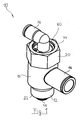
- FIG. 1 shows a generally designated 10 check valve with a valve housing 12 which rotatably supports an inlet housing part 14, on which a radially outwardly pointing pipe socket 16 is provided, which constitutes the inlet for the check valve 10.
- the valve housing 12 has a substantially hollow cylindrical shape, which defines a valve channel 18 and has at its end in the drawing above a hexagonal portion 20 which serves as Einschraub Anlagen.
- the valve housing 12 tapers via two shoulders to a threaded connector 22, which forms the outlet of the check valve 10.
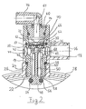
- the Gewiridestutzen 22 is screwed with an external thread 24 in a connecting piece 26 of a pressure accumulator 28, like out FIG. 2 seen.
- a first radially inwardly stepped shoulder 30 is provided on the valve housing 12, on which a tapered central portion 32 begins, which is enclosed by the hollow cylindrical inlet housing part 14.
- a circumferential outer groove 34 is provided near the shoulder 30, in which a sealing ring 36 is arranged, so that the inlet housing part 14 can be supported on the shoulder 30 and is tightly received.
- a second radially inwardly stepped shoulder 38 is provided as a transition from the central portion 32 to the threaded connector 22.
- another sealing ring 40 which is compressed when screwing the check valve 10 so far that the inlet housing part 14 is clamped between the first shoulder 30 and the connecting piece 26 of the pressure accumulator 28 and the valve housing 12 is sealed to the environment ,
- the pipe socket 16 of the inlet housing part 14 communicates with a circumferential inner groove 42, which circulates in the interior of the inlet housing part 14 and communicates via radial bores 44 in the middle section 32 with the valve channel 18.
- an outer groove is provided which connects the radial bores 44.
- a sliding Control element 46 is arranged, which comprises a closure part 48, a plunger 50 and a control piston 52.
- the control element 46 is arranged in the valve channel 18 such that the closure part 48 protrudes out of the threaded connection 22 and thus into the pressure accumulator 28.
- a circumferential outer groove 54 is further provided, in which after insertion of the control element 46 into the interior of the valve housing 12, a valve sealing ring 56 is inserted, which projects radially beyond the outer groove 54 and cooperates with the end portion of the threaded connector 22 as a valve seat.
- the threaded connector 22 has frontally to a 45 ° inwardly and upwardly inclined circumferential chamfer 58.
- the plunger 50 points into the valve channel 18 and, at its end remote from the closure part 48, carries the control piston 52 which, together with a cylindrical inner wall of the valve housing 12 and a sealing plug 60, delimits a control chamber 62.
- a circumferential around the control piston 52 lip seal 64 provides in a circumferential groove 52 of the control piston.
- the control piston 52 also has on its front side a counterbore 66, at the bottom of a throttle bore 68 is provided with a small diameter.
- valve plate 70 which by means of a radial bias standing slotted fixing ring 72 is held under axial play over the throttle bore 68.
- the valve plate 70 together with the bottom of the counterbore 66, opens a check valve which opens in the direction of the control chamber, that is to say a barrier which prevents backflow of fluid ir in the opposite direction (towards the valve channel).
- the closure plug 60 which is also secured axially with a radial spring ring 74, centrally has a bore 61 which has a in FIG. 2 angled illustrated control port 76, but which may also be running, with a pilot valve, not shown here is in communication.
- FIG. 3 shows the check valve 10 with the control element 46 in a closed position in which the valve sealing ring 56 bears tightly against the inclined chamfer 58.
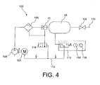
- FIG. 4 schematically shows the use of the check valve 10 in a compressed air supply unit 100th
- a driven by an engine 102 compressor 104 is connected via an air dryer 106 and the check valve 10 to the pressure accumulator 28.
- shut-off valve 108 is connected, which is connected via a pressure line 110 with consumers, not shown.
- a window pressure switch 112 is connected to the pressure accumulator 28. It closes when falling below a lower setpoint pressure and opens when an upper setpoint pressure for the pressure accumulator 28 is exceeded and thus controls the motor 102 as required via an electrical line 113. Also via line 113, the pressure switch 112 controls a vent valve 114 which is connected to the control connection piece 76 the check valve 10 and to a vent port of the air dryer 106 is connected. The vent valve 114 can either be closed by the pressure switch 112 or opened to the environment.
- the pressure switch 112 may also use information from a timer 116 and a speed sensor 118 that measures the speed of the motor 102.
- vent valve 114 is actuated electromagnetically by an electromechanical pressure switch 112.
- the pressure switch 112 may actuate the vent valve directly mechanically. Furthermore, the pressure switch 112 may also be designed as an electronic controller.
- the check valve 10 does not comprise a spring acting on the closure part 48.
- a spring may be provided to produce a bias of the closure member 48 according to the pending pressures.
- control piston 52 Since the control piston 52 has a smaller active pressure surface on the side of the valve channel 18 due to the plunger 50 than in the control chamber 62, the control element 46 is moved into an open position in the direction of the pressure accumulator 28. Regardless of any occurring inlet-side pressure fluctuations, the closure member 48 remains forcibly safely opened by the differential pressure.
- vent valve 114 When the upper target pressure in accumulator 28 is reached, pressure switch 112 opens vent valve 114 and stops compressor 104. The opening of vent valve 114 results in a rapid pressure drop in control chamber 62 because restrictor bore 68 limits fluid delivery. As a result, the force acting upwards in the closing direction predominates on the control piston 52, and the control element 46 is moved into a closed position, in which the closure part 48 abuts with the valve sealing ring 56 on the inclined chamfer 58 and thus closes the check valve 10.
Landscapes
- Engineering & Computer Science (AREA)
- General Engineering & Computer Science (AREA)
- Mechanical Engineering (AREA)
- Check Valves (AREA)
- Compressor (AREA)
Description
- Die Erfindung betrifft ein Rückschlagventil mit
- einem Ventilgehäuse, welches einen Einlass, einen Auslass und einen Ventilkanal aufweist, der einen Ventilsitz umfasst und den Einlass mit dem Auslass verbindet,
- einem Verschlussteil, das mit dem Ventilsitz zusammenarbeitet, und
- einem Stößel, der das Verschlussteil trägt,
- ein vom Verschlussteil abgelegenes Ende des Stößels einen Steuerkolben trägt und
- der Steuerkolben zusammen mit einer Zylinderwand eine Steuerkammer begrenzt.
- Ein derartiges Rückschlagventil ist in der
US 2,516,247 A beschrieben. Darin wird ein einer Flüssigkeitspumpe nachgeschaltetes Rückschlagventil beschrieben, bei welchem ein auf das Verschlussteil wirkender Steuerkolben in einer Steuerkammer läuft. Das Verschlussteil ist so ausgestaltet, dass der Rückfluss der Flüssigkeit das Rückschlagventil schließt, sobald die Flüssigkeitspumpe deaktiviert wird. Um den mit einem zu schnellen Schließen verbundenen Anschlag des Verschlussteils am Ventilsitz zu verhindern, wird dabei die Steuerkammer über eine Drossel in den Ventilkanal entleert, wodurch die Bewegung des Steuerkolbens und damit die Bewegung des Verschlussteils gebremst wird. - Ähnliche Rückschlagventile sind in der,
US 4,312,376 A , derDE 34 04 982 A1 und derGB 25123 A - Die Erfindung betrifft ferner ein Verfahren zum Betreiben einer Druckluftversorgungseinheit.
- Eine Druckluftversorgungseinheit, die beispielsweise in einem dentalmedizinischen Arbeitsplatz zur Bereitstellung von Druckluft verwendet wird, weist einen Druckspeicher auf, der mit Hilfe eines Kompressors befüllt wird. Wird aus dem Druckspeicher Druckluft entnommen, so sinkt der Druck der im Druckspeicher enthaltenen Luft, sodass bei Unterschreiten eines vorgebbaren Mindestdrucks ein mit dem Druckspeicher verbundener Druckschalter den Kompressor in Gang setzt, um den Druckspeicher erneut zu befüllen.
- Zwischen dem Druckspeicher und dem Kompressor ist dabei ein Rückschlagventil eingangs genannter Art vorgesehen, das verhindert, dass bei ausgeschaltetem Kompressor die Druckluft entgegen der Förderrichtung des Kompressors aus dem Druckspeicher entweicht.
- Bisher bekannte Rückschlagventile umfassen dazu Verschlussteile, die mit Hilfe einer Feder an einen Ventilsitz angedrückt werden. Sobald der am Verschlussteil einlassseitig anliegende Druck die Federkraft übersteigt, öffnet das Rückschlagventil und die Luft kann vom Kompressor zum Druckspeicher gefördert werden.
- Eine derartige Konstruktion stellt ein Feder-Masse-System dar, das ein Eigenschwingverhalten aufweist, welches durch Druckschwankungen im Luftstrom zu Schwingungen angeregt werden kann. Insbesondere Kolbenkompressoren erzeugen häufig einen Luftstrom, der mit der Drehfrequenz des Antriebsmotors mehr oder weniger stark pulsiert, sodass das Verschlussteil des Rückschlagventils während des Betriebs des Kompressors je nach anstehendem Druck mehr oder weniger stark auf den Ventilsitz hämmert, was zu störender Ge- räuschentwicklung führen kann. Dies ist insbesondere bei der Verwendung der Druckluftversorgungseinheit in einer Pa- tientenumgebung wie im Falle eines dentalmedizinischen Ar- beitsplatzes unerwünscht.
- Es ist daher Aufgabe der Erfindung, ein Rückschlagventil der eingangs genannten Art zur Verfügung zu stellen, bei welchem die Geräuschentwicklung vermindert ist.
- Es ist weiter Aufgabe der Erfindung ein Verfahren zum Be- trieb einer Druckluftversorgungseinheit anzugeben, bei wel- chem die Geräuschentwicklung vermindert ist.
- Diese Aufgabe ist durch ein Rückschlagventil der eingangs genannten Art gelöst, bei dem
- die Steuerkammer mit einem Steueranschluss zum Entlüften der Steuerkammer in Verbindung steht, und
- die Steuerkammer über einen Verbindungskanal, dessen Querschnitt so gewählt ist, dass er als Drossel wirkt, mit dem Ventilkanal verbunden ist, wodurch beim Entlüften über den Steueranschluss der Druck in der Steuerkammer schneller abfällt als im Ventilkanal
- Ein solches Eigenmedium-betätigtes Rückschlagventil ist ein steuerbares Rückschlagventil, bei welchem das Verschlussteil bistabil mit Hilfe des Steuerkolbens zwischen zwei unterschiedlichen Lagen hin- und herbewegt werden kann. Erhöht sich einlassseitig der Druck im Ventilkanal beispielsweise durch Anschalten eines vorgeschalteten Kompressors, so tritt das durch das Rückschlagventil hindurchtretende Medium, meist Druckluft, über den Verbindungskanal in die Steuerkammer ein. Eine dann stirnseitig auf den Steuerkolben wirkende Kraft bewegt das Verschlussteil zwangsläufig in eine geöffnete Stellung. Der Querschnitt des Verbindungskanals kann dabei so klein gewählt werden, dass der Druck in der Steuerkammer trotz der Druckschwankungen am Einlass des Rückschlagventils weitgehend konstant bleibt, sodass das Verschlussteil in der geöffneten Stellung verharrt.
- Ein weiterer Vorteil des Rückschlagventils betrifft die Entlüftung der Druckleitung. Die zwischen Rückschlagventil und Auslass des Kompressors liegenden Komponenten und Verbindungsleitungen werden nämlich bei abgeschaltetem Kompressor zwangsentlüftet, damit der Kompressor beim Wiedereinschalten gut anlaufen kann.
- Beim erfindungsgemäßen Rückschlagventil kann die Entlüftung am Rückschlagventil über den Steueranschluss und die Steuerkammer erfolgen. Durch Entlüften der Steuerkammer schließt sich das Verschlussteil, wobei noch anliegende Druckkräfte auf der von der Steuerkammer abliegenden Stirnfläche des Steuerkolbens ein sicheres Schließen des Verschlussteils garantieren.
- Eine Geräuschentwicklung tritt somit gemäß der Erfindung nur einmalig beim Öffnen und einmalig beim Schließen des Ventils auf.
- Nach einer Weiterbildung der Erfindung ist vorgesehen, dass der Steuerkolben mit seiner stößelseitigen Stirnfläche mit dem Ventilkanal kommuniziert.
- Dadurch, dass der Steuerkolben an der von der Steuerkammer abgelegenen Seite mit dem Druck beaufschlagt wird, der einlassseitig am Ventilkanal anliegt, wird das Verschlussteil zwangsweise geschlossen, sobald die Steuerkammer entlüftet wird. Der relativ kleine Querschnitt des Verbindungskanals wirkt dabei als Drossel, sodass der Druck in der Steuerkammer schneller abfällt als im Ventilkanal.
- Nach einer Weiterbildung der Erfindung ist vorgesehen, dass der Verbindungskanal eine Rückströmsperre aufweist, die ein Rückströmen von Medium von der Steuerkammer in den Ventilkanal verhindert.
- Nach einer Entlüftung der Steuerkammer befindet sich in dieser Umgebungsluft unter entsprechendem Umgebungsluftdruck. Durch die Rückströmsperre wird verhindert, dass diese ungereinigte Luft oder ungetrocknete Luft in das Innere des Druckspeichers gelangt. Weiter verhindert die Rückströmsperre, dass das Medium aufgrund eines Druckabfalls im Ventilkanal, der beispielsweise nach dem Öffnen des Verschlussteils zum Druckspeicher auftreten kann, von der Steuerkammer zurück in den Ventilkanal gelangt.
- Nach einer Weiterbildung der Erfindung ist vorgesehen, dass der Verbindungskanal die Steuerkammer über den Steuerkolben mit dem Ventilkanal verbindet.
- Dies stellt eine einfache Herstellungsmöglichkeit dar, da der Verbindungskanal eine einfache Bohrung durch den Steuerkolben sein kann. Durch geeignete Wahl des Durchmessers kann der entlang des Verbindungskanals abfallende Differenzdruck eingestellt werden, sodass ein sicheres Schließen des Rückschlagventils beim Entlüften der Steuerkammer gewährleistet ist.
- Nach einer Weiterbildung der Erfindung ist vorgesehen, dass der Steueranschluss an einem Verschlussstopfen vorgesehen ist, der die Zylinderwand der Steuerkammer abschließt.
- Über den Verschlussstopfen, der als separates Bauteil in das Ventilgehäuse eingesetzt werden kann, ist das Innere des Rückschlagventils bei der Fertigung oder zur Wartung zugänglich. Bei Verwendung eines abgewinkelten Steueranschluss-Stutzens kann die Ausrichtung des Steueranschlusses durch Verdrehen des Verschlussstopfens frei gewählt werden.
- Nach einer Weiterbildung der Erfindung ist vorgesehen, dass der Ventilsitz eine umlaufende geneigte, vorzugsweise unter etwa 45° angestellte Fase am Ventilkanal umfasst, und das Verschlussteil einen Dichtring in einer umlaufenden Außennut umfasst, der mit der Fase zusammenarbeitet.
- Dadurch wird ein dichtes weiches Schließen des Rückschlagventils gewährleistet. Zu Fertigungszwecken ist es vorteilhaft, wenn das Verschlussteil kleinere Außenabmessungen als die Innenabmessung des Ventilsitzes hat, sodass das Verschlussteil einlassseitig durch den Ventilsitz hindurchgeschoben werden kann. Danach kann der Dichtring in die Außennut eingebracht werden, sodass das Verschlussteil mit dem Dichtring gegen den Ventilsitz arbeitet.
- Nach einer Weiterbildung ist vorgesehen, dass die Fase am stirnseitigen Ende eines hohlen Auslassstutzens vorgesehen ist.
- Wird der Auslassstutzen mit einem Gewinde versehen, so dient dieser zugleich als Befestigungsmittel am Druckspeicher sowie als Ventilsitz, sodass im Inneren des Ventilkanals keine spezielle Schulter als Ventilsitz ausgebildet werden muss.
- Nach einer Weiterbildung ist vorgesehen, dass das Ventilgehäuse in einem axialen Teilbereich von einem hohlzylindrischen Einlassgehäuseteil dicht umschlossen wird, das den Einlass umfasst und gegenüber dem Ventilgehäuse drehbar ist.
- Ein separat drehbares Einlassgehäuseteil ermöglicht eine Ausrichtung des Einlasses, was einen flexiblen Einsatz des Rückschlagventils ermöglicht.
- Nach einer Weiterbildung ist vorgesehen, dass eine Außenfläche des Ventilgehäuses radial progressiv nach innen gestufte Stützschultern aufweist, wobei eine erste Stützschulter das Einlassgehäuseteil stützt und eine zweite Stützschulter des Ventilgehäuses mit einem Anschlussstutzen eines Druckspeichers zusammenarbeitet.
- Werden an den Stützschultern Dichtringe vorgesehen, so bilden die Stützschultern eine einfache Möglichkeit, das Ventil dicht am Anschlussstutzen beispielsweise eines Druckspeichers zu befestigen und zugleich das Einlassgehäuseteil zu sichern.
- Hinsichtlich des Verfahrens wird die Aufgabe erfindungsgemäß gelöst durch ein Verfahren zum Betreiben einer Druckluftversorgungseinheit, das folgende Schritte umfasst:
- Bereitstellen eines Druckspeichers;
- Bereitstellen eines erfindungsgemäßen Rückschlagventils, dessen Auslass mit dem Druckspeicher verbunden ist;
- Bereitstellen eines Kompressors, der mit dem Einlass des Rückschlagventils verbunden ist;
- Bereitstellen eines Druckschalters, der den Kompressor und ein Entlüftungsventil ansteuert, das mit dem Steueranschluss des Rückschlagventils verbunden ist;
- Schließen des Entlüftungsventils bei Unterschreiten eines Mindestdrucks im Druckspeicher, sodass sich in der Steuerkammer des Rückschlagventils durch den Kompressor ein Druck aufbaut, der das Rückschlagventil zum Druckspeicher hin öffnet;
- Öffnen des Entlüftungsventils bei Erreichen eines Solldrucks im Druckspeicher, sodass das Verschlussteil des Rückschlagventils geschlossen wird.
- Da der Steueranschluss des Eigenmedium-betätigten Rückschlagventils zugleich zum Entlüften der Druckleitungen verwendet wird, ist das Rückschlagventil durch den Druckschalter steuerbar. Dabei ist dank der Eigenbetätigung ein sicheres leises Öffnen und Schließen des Ventils gewährleistet, da vom Kompressor erzeugte Druckschwankungen nicht zu einem Schwingen des Verschlussteils führen. Die Druckluftversorgungseinheit zeigt somit eine geringere Geräuschentwicklung.
- Nach einer Weiterbildung ist vorgesehen, dass zwischen Kompressor und Rückschlagventil ein Trockner vorgesehen ist, der ebenfalls über das Entlüftungsventil entlüftet wird.
- Der Trockner trocknet die vom Kompressor kommende Druckluft, sodass sich im Druckspeicher nur getrocknete und gereinigte Druckluft befindet, die zur Verwendung im dentalmedizinischen Bereich geeignet ist. Dadurch, dass der Trockner und das Rückschlagventil am Druckspeicher über dasselbe Entlüftungsventil entlüftet werden, muss am Druckschalter kein weiteres Entlüftungsventil vorgesehen werden. Besonders vorteilhaft ist in diesem Zusammenhang eine Rückströmsperre im Verbindungskanal, da vom Entlüftungsventil auch Bereiche des Trockners entlüftet werden, die feuchte Luft enthalten und daher durch die Rückströmsperre gewährleistet werden muss, dass keine feuchte Luft durch Steueranschluss über den Verbindungskanal in den Ventilkanal und somit in den Druckspeicher gelangt.
- Nach einer Weiterbildung des Verfahrens ist vorgesehen, dass der Druckschalter das Entlüftungsventil in Abhängigkeit von Signalen eines Drucksensors, einer Zeitsteuerung und/oder eines Drehzahlsensors steuert.
- So kann beispielsweise beim Anlaufen des Kompressors das Entlüftungsventil noch geöffnet sein und erst bei Erreichen einer bestimmten Drehzahl oder nach einer gewissen Zeit das Entlüftungsventil geschlossen werden. Falls die Drehzahl beispielsweise aufgrund einer Fehlfunktion des Kompressors nicht nach einer bestimmten Zeit erreicht wird, kann der Druckschalter das Entlüftungsventil geöffnet halten und den Kompressor wieder ausschalten.
- Nachstehend wird die Erfindung anhand von Ausführungsbeispielen unter Bezugnahme auf die Zeichnungen näher erläutert. In diesen zeigen:
- Figur 1
- eine perspektivische Ansicht eines Eigenmedium-betätigten Rückschlagventils;
- Figur 2
- einen Längsschnitt durch das an einen Druckspeicher angeschlossene Rückschlagventil in geöffnetem Zustand;
- Figur 3
- einen Längsschnitt durch das an einen Druckspeicher angeschlossene Rückschlagventil in geschlossenem Zustand;
- Figur 4
- einen schematischen Fluidschaltplan einer Druckluftversorgungseinheit.
-
Figur 1 zeigt ein insgesamt mit 10 bezeichnetes Rückschlagventil mit einem Ventilgehäuse 12, das ein Einlassgehäuseteil 14 drehbar trägt, an welchem ein radial nach außen zeigender Rohrstutzen 16 vorgesehen ist, der den Einlass für das Rückschlagventil 10 darstellt. - Das Ventilgehäuse 12 hat eine im Wesentlichen hohlzylindrische Form, die einen Ventilkanal 18 vorgibt und weist an seinem in der Zeichnung oben gelegenen Ende einen Sechskant-Abschnitt 20 auf, der als Einschraubhilfe dient.
- Ausgehend vom Sechskant-Abschnitt 20 verjüngt sich das Ventilgehäuse 12 über zwei Schultern zu einem Gewindestutzen 22 hin, der den Auslass des Rückschlagventils 10 bildet. Der Gewiridestutzen 22 ist mit einem Außengewinde 24 in einen Anschlussstutzen 26 eines Druckspeichers 28 eingeschraubt, wie aus
Figur 2 ersichtlich. - Dabei ist am Ventilgehäuse 12 eine erste radial nach innen gestufte Schulter 30 vorgesehen, an welcher ein verjüngter Mittelabschnitt 32 beginnt, der vom hohlzylindrischen Einlassgehäuseteil 14 umschlossen ist. Am Mittelabschnitt 32 ist nahe der Schulter 30 eine umlaufende Außennut 34 vorgesehen, in welcher ein Dichtring 36 angeordnet ist, sodass sich das Einlassgehäuseteil 14 an der Schulter 30 abstützten kann und dabei dicht aufgenommen ist.
- Eine zweite radial nach innen gestufte Schulter 38 ist als Übergang vom Mittelabschnitt 32 zum Gewindestutzen 22 vorgesehen. An dieser zweiten Schulter 38 liegt ein weiterer Dichtring 40 an, der beim Einschrauben des Rückschlagventils 10 so weit komprimiert wird, dass das Einlassgehäuseteil 14 zwischen der ersten Schulter 30 und dem Anschlussstutzen 26 des Druckspeichers 28 eingespannt wird und das Ventilgehäuse 12 zur Umgebung hin abgedichtet ist.
- Der Rohrstutzen 16 des Einlassgehäuseteiles 14 steht mit einer umlaufenden Innennut 42 in Verbindung, die im Inneren des Einlassgehäuseteils 14 umläuft und über Radialbohrungen 44 im Mittelabschnitt 32 mit dem Ventilkanal 18 kommuniziert. Dadurch wird eine fluidische Verbindung vom Rohrstutzen 16 zum Ventilkanal 18 in jeder Drehlage des Einlassgehäuseteils 14 bezüglich des Ventilgehäuses 12 gewährleistet.
- In einem nicht gezeigten weiteren Ausführungsbeispiel ist anstatt oder zusätzlich zur Innennut 42 des Einlassgehäuseteils im Mittelabschnitt 32 des Ventilgehäuses 12 eine Außennut vorgesehen, die die Radialbohrungen 44 verbindet.
- Im Inneren des Ventilgehäuses 12 ist ein verschiebbares Steuerelement 46 angeordnet, das ein Verschlussteil 48, einen Stößel 50 und einen Steuerkolben 52 umfasst.
- Das Steuerelement 46 ist so im Ventilkanal 18 angeordnet, dass das Verschlussteil 48 aus dem Gewindestutzen 22 heraus und somit in den Druckspeicher 28 hinein ragt. Am Verschlussteil 48 ist ferner eine umlaufende Außennut 54 vorgesehen, in welche nach dem Einbringen des Steuerelements 46 ins Innere des Ventilgehäuses 12 ein Ventildichtring 56 eingesetzt wird, der über die Außennut 54 radial übersteht und mit dem Endabschnitt des Gewindestutzens 22 als Ventilsitz zusammenarbeitet. Der Gewindestutzen 22 weist dazu stirnseitig eine 45° nach innen und oben geneigte umlaufenden Fase 58 auf.
- Ausgehend von dem Verschlussteil 48 zeigt der Stößel 50 in den Ventilkanal 18 und trägt an seinem vom Verschlussteil 48 abgelegenen Ende den Steuerkolben 52, der zusammen mit einer zylindrischen Innenwand des Ventilgehäuses 12 und einem Verschlussstopfen 60 eine Steuerkammer 62 begrenzt.
- Für eine dichte Aufnahme des Steuerkolbens 52 in der zylindrischen Wand sorgt eine um den Steuerkolben 52 umlaufende Lippendichtung 64 in einer Umfangsnut des Steuerkolbens 52.
- Der Steuerkolben 52 weist ferner auf seiner Stirnseite eine Senkbohrung 66 auf, an deren Grund eine Drosselbohrung 68 mit einem kleinen Durchmesser vorgesehen ist. Ein transversaler Durchgang 69 in einem oberen Kopf des Stößels 50 bildet zusammen mit der Drosselbohrung 68 einen Verbindungskanal zwischen dem Ventilkanal 18 und der Steuerkammer 62.
- Der Boden der Senkbohrung 66 wird von einem Ventilplättchen 70 überdeckt, das mit Hilfe eines unter radialer Vorspannung stehenden geschlitzten Fixierringes 72 unter axialem Spiel über der Drosselbohrung 68 gehalten wird. Das Ventilplättchen 70 bildet zusammen mit dem Boden der Senkbohrung 66 eine in Richtung zur Steuerkammer öffnendes Rückschlagventil, also eine Sperre, die ein Zurückströmen von Fluid ir entgegengesetzter Richtung (zum Ventilkanal hin) verhindert.
- Der Verschlussstopfen 60, der ebenfalls mit einem Radialspringring 74 axial gesichert ist, weist mittig eine Bohrung 61 auf, die über einen in
Figur 2 abgewinkelt dargestellten Steueranschlussstutzen 76, der aber auch gerade ausgeführt sein kann, mit einem hier nicht dargestellten Vorsteuerventil in Verbindung steht. -
Figur 3 zeigt das Rückschlagventil 10 mit dem Steuerelement 46 in einer geschlossenen Stellung, bei welcher der Ventildichtring 56 dicht an der schrägen Fase 58 anliegt. -
Figur 4 zeigt schematisch die Verwendung des Rückschlagventils 10 in einer Druckluftversorgungseinheit 100. - Ein von einem Motor 102 angetriebener Kompressor 104 ist über einen Lufttrockner 106 und das Rückschlagventil 10 mit dem Druckspeicher 28 verbunden.
- An den Druckspeicher 28 ist eine Absperrarmatur 108 angeschlossen, die über eine Druckleitung 110 mit nicht gezeigten Verbrauchern verbunden ist.
- Ein Fenster-Druckschalter 112 ist mit dem Druckspeicher 28 verbunden. Er schließt bei Unterschreiten eines unteren Solldruckes und öffnet bei Überschreiten eines oberen Solldruck für den Druckspeicher 28 und steuert so über eine e-lektrische Leitung 113 den Motor 102 bedarfsgemäß. Ebenfalls über die Leitung 113 steuert der Druckschalter 112 ein Entlüftungsventil 114 an, das an den Steueranschlussstutzen 76
des Rückschlagventils 10 und an einen Entlüftungsanschluss des Lufttrockners 106 angeschlossen ist. Das Entlüftungsventil 114 kann vom Druckschalter 112 entweder geschlossen werden oder zur Umgebung hin geöffnet werden. - Zur Steuerung des Motors 102 und des Entlüftungsventils 114 kann der Druckschalter 112 zudem Informationen eines Zeitgebers 116 und eines Drehzahlsensors 118 heranziehen, der die Drehzahl des Motors 102 misst.
- Im vorliegenden Ausführungsbeispiel wird das Entlüftungsventil 114 elektromagnetisch von einem elektromechanischen Druckschalter 112 betätigt.
- Nach einem nicht gezeigten Ausführungsbeispiel kann der Druckschalter 112 das Entlüftungsventil jedoch auch direkt mechanisch betätigen. Ferner kann der Druckschalter 112 auch als elektronische Steuerung ausgebildet sein.
- Wie aus dem gezeigten Ausführungsbeispiel ersichtlich umfasst das Rückschlagventil 10 keine auf das Verschlussteil 48 wirkende Feder. Nach einem nicht gezeigten Ausführungsbeispiel kann jedoch auch eine Feder vorgesehen sein, um entsprechend der anstehenden Drücke eine Vorspannung des Verschlussteils 48 zu erzeugen.
- Die Druckluftversorgungseinheit 100 arbeitet wie folgt:
- Das Entlüftungsventil 114 wird vom Druckschalter 112 geschlossen und der Kompressor 104 angefahren, sobald der untere Solldruck im Druckspeicher 28 unterschritten ist. Über den Einlass des Rückschlagventils 10 tritt verdichtete Druckluft in den Ventilkanal 18 ein und gelangt bei zunächst noch geschlossenem Rückschlagventil 10 über den Durchgang 69 im Steuerkolben 52 und die Drosselbohrung 68 in die Steuerkammer 62, wo sich wegen des geschlossenen Entlüftungsventils 114 ein Druck aufbaut.
- Da der Steuerkolben 52 aufgrund des Stößels 50 auf der Seite des Ventilkanals 18 eine kleinere aktive Druckfläche aufweist als bei der Steuerkammer 62, wird das Steuerelement 46 in eine Offenstellung in Richtung des Druckspeichers 28 bewegt. Unabhängig von eventuell auftretenden einlassseitigen Druckschwankungen bleibt das Verschlussteil 48 durch die Differenzdruckbeaufschlagung zwangsweise sicher geöffnet.
- Wird der obere Solldruck im Druckspeicher 28 erreicht, öffnet der Druckschalter 112 das Entlüftungsventil 114 und stoppt den Kompressor 104. Das Öffnen des Entlüftungsventils 114 führt zu einem schnellen Druckabfall in der Steuerkammer 62, da die Drosselbohrung 68 die Fluidzufuhr begrenzt. Dadurch überwiegt die nach oben in Schließrichtung wirkende Kraft auf den Steuerkolben 52, und das Steuerelement 46 wird in eine Schließstellung bewegt, bei der das Verschlussteil 48 mit dem Ventildichtring 56 an der schrägen Fase 58 anliegt und somit das Rückschlagventil 10 schließt.
- Bedingt durch den Ventildichtring 56 am Verschlussteil 48 ist das Schließen des Rückschlagventils 10 nahezu unhörbar. Ein eventuell erwünscht hörbares Schaltgeräusch beim Öffnen kann bei geändertem Interesse durch geeignete Dämpfungselemente vermindert werden.
Claims (12)
- Rückschlagventil (10) mit- einem Ventilgehäuse (12), welches einen Einlass (16), einen Auslass (22) und einen Ventilkanal (18) aufweist, der einen Ventilsitz (58) umfasst und den Einlass (16) mit dem Auslass (22) verbindet,- einem Verschlussteil (48), das mit dem Ventilsitz (58) zusammenarbeitet, und- einem Stößel (50), der das Verschlussteil (48) trägt,wobei- ein vom Verschlussteil (48) abgelegenes Ende des Stößels (50) einen Steuerkolben (52) trägt und- der Steuerkolben (52) zusammen mit einer Zylinder- wand eine Steuerkammer (62) begrenzt,dadurch gekennzeichnet, dass- die Steuerkammer (62) mit einem Steueranschluss (76) zum Entlüften der Steuerkammer (62) in Verbindung steht, und- die Steuerkammer (62) über einen Verbindungskanal (66, 68), dessen Querschnitt so gewählt ist, dass er als Drossel wirkt, mit dem Ventilkanal (18) verbunden ist, wodurch beim Entlüften über den Steueranschluss (76) der Druck in der Steuerkammer (62) schneller abfällt als im Ventilkanal (18).
- Rückschlagventil nach Anspruch 1, dadurch gekennzeichnet, dass der Steuerkolben (52) mit seiner stößelseitigen Stirnfläche mit dem Ventilkanal (18) kommuniziert.
- Rückschlagventil nach Anspruch 1 oder 2, dadurch gekennzeichnet, dass der Verbindungskanal (66, 68) eine Rückströmsperre (70, 72) aufweist, die ein Rückströmen von Medium von der Steuerkammer (62) in den Ventilkanal (18) verhindert.
- Rückschlagventil nach einem der vorherigen Ansprüche, dadurch gekennzeichnet, dass der Verbindungskanal (66, 68) die Steuerkammer (62) über den Steuerkolben (52) mit dem Ventilkanal (18) verbindet.
- Rückschlagventil nach einem der vorherigen Ansprüche, dadurch gekennzeichnet, dass der Steueranschluss (76) an einem Verschlussstopfen (60) vorgesehen ist, der die Zylinderwand der Steuerkammer (62) abschließt.
- Rückschlagventil nach einem der vorherigen Ansprüche, dadurch gekennzeichnet, dass der Ventilsitz eine umlaufende geneigte, vorzugsweise unter etwa 45° angestellte Fase (58) am Ventilkanal (18) umfasst, und das Verschlussteil (48) einen Dichtring (56) in einer umlaufenden Außennut (54) umfasst, der mit der Fase (58) zusammenarbeitet.
- Rückschlagventil nach Anspruch 6, dadurch gekennzeichnet, dass die Fase (58) am stirnseitigen Ende eines hohlen Auslassstutzens (22) vorgesehen ist.
- Rückschlagventil nach einem der vorherigen Ansprüche, dadurch gekennzeichnet, dass das Ventilgehäuse (12) in einem axialen Teilbereich (32) von einem hohlzylindrischen Einlassgehäuseteil (14) dicht umschlossen wird, das den Einlass (16) umfasst und gegenüber dem Ventilgehäuse (12) drehbar ist.
- Rückschlagventil nach Anspruch 8, dadurch gekennzeichnet, dass eine Außenfläche des Ventilgehäuses (12) radial progressiv nach innen gestufte Stützschultern (30, 38) aufweist, wobei eine erste Stützschulter (30) das Einlassgehäuseteil (14) stützt und eine zweite Stützschulter (38) des Ventilgehäuses (12) mit einem Anschlussstutzen (26) eines Druckspeichers (28) zusammenarbeitet.
- Verfahren zum Betreiben einer Druckluftversorgungseinheit (100), das folgende Schritte umfasst:- Bereitstellen eines Druckspeichers (28);- Bereitstellen eines Rückschlagventils (10) nach einem der vorherigen Ansprüche, dessen Auslass (22) mit dem Druckspeicher (28) verbunden ist;- Bereitstellen eines Kompressors (102, 104), der mit dem Einlass (16) des Rückschlagventils (10) verbunden ist;- Bereitstellen eines Druckschalters (112), der den Kompressor (102, 104) und ein Entlüftungsventil (114) ansteuert, das mit dem Steueranschluss (64) des Rückschlagventils (10) verbunden ist;- Schließen des Entlüftungsventils (114) bei Unterschreiten eines Mindestdrucks im Druckspeicher, sodass sich in der Steuerkammer (62) des Rückschlagventils (10) durch den Kompressor (102, 104) ein Druck aufbaut, der das Rückschlagventil (10) zum Druckspeicher (28) hin öffnet;- Öffnen des Entlüftungsventils (114) bei Erreichen eines Solldrucks im Druckspeicher (28), sodass das Verschlussteil (48) des Rückschlagventils (10) geschlossen wird.
- Verfahren nach Anspruch 10, dadurch gekennzeichnet, dass zwischen Kompressor (102, 104) und Rückschlagventil (10) ein Trockner (106) vorgesehen ist, der ebenfalls über das Entlüftungsventil (114) entlüftet wird.
- Verfahren nach Anspruch 10 oder 11, dadurch gekennzeichnet, dass der Druckschalter (112) das Entlüftungsventil (114) in Abhängigkeit von Signalen eines Drucksensor, einer Zeitsteuerung (116) und/oder eines Drehzahlsensors (118) steuert.
Applications Claiming Priority (2)
| Application Number | Priority Date | Filing Date | Title |
|---|---|---|---|
| DE201010034867 DE102010034867A1 (de) | 2010-08-19 | 2010-08-19 | Rückschlagventil |
| PCT/EP2011/003861 WO2012022432A1 (de) | 2010-08-19 | 2011-08-02 | Rückschlagventil |
Publications (2)
| Publication Number | Publication Date |
|---|---|
| EP2606264A1 EP2606264A1 (de) | 2013-06-26 |
| EP2606264B1 true EP2606264B1 (de) | 2015-01-14 |
Family
ID=44629767
Family Applications (1)
| Application Number | Title | Priority Date | Filing Date |
|---|---|---|---|
| EP20110740849 Not-in-force EP2606264B1 (de) | 2010-08-19 | 2011-08-02 | Rückschlagventil |
Country Status (4)
| Country | Link |
|---|---|
| US (1) | US8763638B2 (de) |
| EP (1) | EP2606264B1 (de) |
| DE (1) | DE102010034867A1 (de) |
| WO (1) | WO2012022432A1 (de) |
Families Citing this family (20)
| Publication number | Priority date | Publication date | Assignee | Title |
|---|---|---|---|---|
| US9993762B2 (en) | 2013-05-13 | 2018-06-12 | General Electric Technology Gmbh | Quiet pulse valve |
| US10343098B2 (en) | 2013-05-13 | 2019-07-09 | General Electric Company | Cleaning valve with dampening mechanism |
| ITMI20130403U1 (it) * | 2013-11-19 | 2015-05-20 | Rpe Srl | Valvola, in particolare valvola di scarico di acqua per servizi igienici |
| US20160076665A1 (en) * | 2014-09-17 | 2016-03-17 | Alstom Technology Ltd | Valve with small tank penetration diameter |
| US10092872B2 (en) | 2014-09-17 | 2018-10-09 | General Electric Technology Gmbh | Valve with small vessel penetration diameter |
| CN104265950B (zh) * | 2014-09-30 | 2016-06-08 | 厦门建霖工业有限公司 | 一种出水转换器 |
| CN104315195B (zh) * | 2014-09-30 | 2016-09-07 | 厦门建霖工业有限公司 | 一种两路转换出水系统 |
| JP1527613S (de) * | 2014-10-31 | 2015-06-29 | ||
| JP1527612S (de) * | 2014-10-31 | 2015-06-29 | ||
| CN204328069U (zh) * | 2014-11-17 | 2015-05-13 | 厦门建霖工业有限公司 | 一种新型出水转换器 |
| US10925702B2 (en) | 2015-10-28 | 2021-02-23 | Stoma Ventures, LLC | Dental valve device having a flexible tubing |
| US10010712B2 (en) | 2015-10-28 | 2018-07-03 | Stoma Ventures, LLC | Disposable dental valve device having a check valve |
| US10925701B2 (en) | 2015-10-28 | 2021-02-23 | Stoma Ventures, LLC | Disposable dental valve device having a socket end |
| US9693842B2 (en) | 2015-10-28 | 2017-07-04 | Stoma Ventures, LLC | Disposable dental valve device having a check valve |
| US9980790B2 (en) | 2016-03-28 | 2018-05-29 | Stoma Ventures, LLC | Dental valve device having a disposable turret |
| US10247204B2 (en) * | 2016-04-01 | 2019-04-02 | Yamada Manufacturing Co., Ltd. | Hydraulic control apparatus and hydraulic control method |
| US11092980B2 (en) | 2016-11-16 | 2021-08-17 | General Electric Technology Gmbh | Pulse valve with pressure vessel penetration |
| GB2579628B (en) * | 2018-12-07 | 2021-07-21 | Corplex Plastics Uk Ltd | Bag side connector for a BIB package |
| US12239501B2 (en) | 2019-08-15 | 2025-03-04 | Stoma Ventures, LLC | Dental valve tailpiece |
| CN216407869U (zh) * | 2021-06-22 | 2022-04-29 | 科际精密股份有限公司 | 气压调节装置 |
Family Cites Families (9)
| Publication number | Priority date | Publication date | Assignee | Title |
|---|---|---|---|---|
| GB190925123A (en) * | 1909-04-05 | 1910-09-15 | Reinhold Breitkreuz | Improvements in Automatic Valves for Water Pipes. |
| US1055161A (en) * | 1910-09-08 | 1913-03-04 | Geissinger Regulator Company | Fluid-pressure-operated valve. |
| US2516247A (en) * | 1949-02-08 | 1950-07-25 | Sadye Florence Gelb | Nonreturn flow valve |
| US4312376A (en) * | 1980-05-23 | 1982-01-26 | Transamerica Delaval Inc. | Pressure-sustaining valve |
| DE3404982A1 (de) | 1984-02-11 | 1985-08-22 | Deutsche Babcock Werke AG, 4200 Oberhausen | Schnell schliessendes rueckschlagventil |
| SE459270B (sv) * | 1985-02-26 | 1989-06-19 | Bahco Hydrauto Ab | Ventilarrangemang foer styrning av tryckmediumfloede genom en tryckmediumledning |
| DE3910025A1 (de) * | 1989-03-28 | 1990-10-04 | Krauss Maffei Ag | Gasverschlussventil und verfahren zum steuern einer mit einem solchen gasverschlussventil versehenen kunststoffverarbeitungsanlage |
| US6457696B1 (en) * | 1998-11-06 | 2002-10-01 | Tgk Co., Ltd. | Pilot operated flow regulating valve |
| US6595757B2 (en) * | 2001-11-27 | 2003-07-22 | Kuei-Hsien Shen | Air compressor control system |
-
2010
- 2010-08-19 DE DE201010034867 patent/DE102010034867A1/de not_active Withdrawn
-
2011
- 2011-08-02 WO PCT/EP2011/003861 patent/WO2012022432A1/de not_active Ceased
- 2011-08-02 EP EP20110740849 patent/EP2606264B1/de not_active Not-in-force
-
2013
- 2013-02-19 US US13/769,987 patent/US8763638B2/en not_active Expired - Fee Related
Also Published As
| Publication number | Publication date |
|---|---|
| US8763638B2 (en) | 2014-07-01 |
| WO2012022432A1 (de) | 2012-02-23 |
| US20130153039A1 (en) | 2013-06-20 |
| DE102010034867A1 (de) | 2012-02-23 |
| EP2606264A1 (de) | 2013-06-26 |
Similar Documents
| Publication | Publication Date | Title |
|---|---|---|
| EP2606264A1 (de) | Rückschlagventil | |
| WO2011076467A1 (de) | Kolbenpumpe für eine hydraulische fahrzeugbremsanlage | |
| DE102007016134A1 (de) | Kraftstoff-Hochdruckpumpe | |
| EP1549869A1 (de) | Druckbegrenzungsventil | |
| DE102012218903B4 (de) | Hydraulische Ventilanordnung und hydraulische Maschinenanordnung mit einer derartigen Ventilanordnung | |
| DE112014003997T5 (de) | Fluidsteuerventil | |
| EP3645885B1 (de) | Hochdruckreinigungsgerät | |
| EP2229532B1 (de) | Hubkolbenverdichter | |
| DE10037527A1 (de) | Piezoelektrische Einspritzeinrichtung | |
| EP4086491B1 (de) | Ventilanordnung | |
| WO2008125267A1 (de) | Hochdruckreinigungsgerät | |
| EP1828651B1 (de) | Druckbegrenzungsventil mit reduzierter differenzfläche | |
| DE2651133A1 (de) | Dosierventil fuer unter druck arbeitende schmiersysteme | |
| EP3238637B1 (de) | Druckgasbetriebenes instrument, insbesondere chirurgisches instrument | |
| DE19614446C1 (de) | Fettpresse | |
| DE19961963A1 (de) | Dämpfkrafteinrichtung mit verstellbarer Dämpfkraft | |
| DE102006016318A1 (de) | Schraubenverdichter mit Entlastungsventil | |
| EP3008343B1 (de) | Vakuumpumpe sowie verfahren zum betreiben einer vakuumpumpe | |
| EP2275037B1 (de) | Druckgasbetriebenes Instrument | |
| DE102009060188B4 (de) | Verstellventil für die Verstellung des Fördervolumens einer Verdrängerpumpe mit Kaltstartfunktion | |
| DE102006035054B4 (de) | Hydraulischer Dämpfer für eine Fahrzeugbremsanlagen-Kolbenpumpe | |
| DE102011101641B4 (de) | Ventil und Pumpenanordnung mit einem derartigen Ventil | |
| EP3529492B1 (de) | Hochdruckpumpe für ein kraftstoffeinspritzsystem | |
| DE202018105657U1 (de) | Kolbenpumpe zur Förderung von Schmierstoffen mit einer veränderbaren Zahl aktiver Pumpenelemente | |
| DE202017003786U1 (de) | Ventilanordnung und Ventilbaugruppe |
Legal Events
| Date | Code | Title | Description |
|---|---|---|---|
| PUAI | Public reference made under article 153(3) epc to a published international application that has entered the european phase |
Free format text: ORIGINAL CODE: 0009012 |
|
| 17P | Request for examination filed |
Effective date: 20130208 |
|
| AK | Designated contracting states |
Kind code of ref document: A1 Designated state(s): AL AT BE BG CH CY CZ DE DK EE ES FI FR GB GR HR HU IE IS IT LI LT LU LV MC MK MT NL NO PL PT RO RS SE SI SK SM TR |
|
| DAX | Request for extension of the european patent (deleted) | ||
| GRAP | Despatch of communication of intention to grant a patent |
Free format text: ORIGINAL CODE: EPIDOSNIGR1 |
|
| RIC1 | Information provided on ipc code assigned before grant |
Ipc: F16K 31/124 20060101ALI20140702BHEP Ipc: F17D 1/04 20060101ALI20140702BHEP Ipc: F16K 15/06 20060101AFI20140702BHEP Ipc: F16K 31/122 20060101ALI20140702BHEP |
|
| INTG | Intention to grant announced |
Effective date: 20140731 |
|
| GRAS | Grant fee paid |
Free format text: ORIGINAL CODE: EPIDOSNIGR3 |
|
| GRAA | (expected) grant |
Free format text: ORIGINAL CODE: 0009210 |
|
| AK | Designated contracting states |
Kind code of ref document: B1 Designated state(s): AL AT BE BG CH CY CZ DE DK EE ES FI FR GB GR HR HU IE IS IT LI LT LU LV MC MK MT NL NO PL PT RO RS SE SI SK SM TR |
|
| REG | Reference to a national code |
Ref country code: GB Ref legal event code: FG4D Free format text: NOT ENGLISH |
|
| REG | Reference to a national code |
Ref country code: CH Ref legal event code: EP |
|
| REG | Reference to a national code |
Ref country code: IE Ref legal event code: FG4D Free format text: LANGUAGE OF EP DOCUMENT: GERMAN |
|
| REG | Reference to a national code |
Ref country code: AT Ref legal event code: REF Ref document number: 707248 Country of ref document: AT Kind code of ref document: T Effective date: 20150215 |
|
| REG | Reference to a national code |
Ref country code: DE Ref legal event code: R096 Ref document number: 502011005658 Country of ref document: DE Effective date: 20150226 |
|
| REG | Reference to a national code |
Ref country code: NL Ref legal event code: VDEP Effective date: 20150114 |
|
| REG | Reference to a national code |
Ref country code: LT Ref legal event code: MG4D |
|
| REG | Reference to a national code |
Ref country code: SK Ref legal event code: T3 Ref document number: E 18441 Country of ref document: SK |
|
| PG25 | Lapsed in a contracting state [announced via postgrant information from national office to epo] |
Ref country code: BG Free format text: LAPSE BECAUSE OF FAILURE TO SUBMIT A TRANSLATION OF THE DESCRIPTION OR TO PAY THE FEE WITHIN THE PRESCRIBED TIME-LIMIT Effective date: 20150414 Ref country code: HR Free format text: LAPSE BECAUSE OF FAILURE TO SUBMIT A TRANSLATION OF THE DESCRIPTION OR TO PAY THE FEE WITHIN THE PRESCRIBED TIME-LIMIT Effective date: 20150114 Ref country code: LT Free format text: LAPSE BECAUSE OF FAILURE TO SUBMIT A TRANSLATION OF THE DESCRIPTION OR TO PAY THE FEE WITHIN THE PRESCRIBED TIME-LIMIT Effective date: 20150114 Ref country code: SE Free format text: LAPSE BECAUSE OF FAILURE TO SUBMIT A TRANSLATION OF THE DESCRIPTION OR TO PAY THE FEE WITHIN THE PRESCRIBED TIME-LIMIT Effective date: 20150114 Ref country code: FI Free format text: LAPSE BECAUSE OF FAILURE TO SUBMIT A TRANSLATION OF THE DESCRIPTION OR TO PAY THE FEE WITHIN THE PRESCRIBED TIME-LIMIT Effective date: 20150114 Ref country code: NO Free format text: LAPSE BECAUSE OF FAILURE TO SUBMIT A TRANSLATION OF THE DESCRIPTION OR TO PAY THE FEE WITHIN THE PRESCRIBED TIME-LIMIT Effective date: 20150414 Ref country code: ES Free format text: LAPSE BECAUSE OF FAILURE TO SUBMIT A TRANSLATION OF THE DESCRIPTION OR TO PAY THE FEE WITHIN THE PRESCRIBED TIME-LIMIT Effective date: 20150114 |
|
| PG25 | Lapsed in a contracting state [announced via postgrant information from national office to epo] |
Ref country code: RS Free format text: LAPSE BECAUSE OF FAILURE TO SUBMIT A TRANSLATION OF THE DESCRIPTION OR TO PAY THE FEE WITHIN THE PRESCRIBED TIME-LIMIT Effective date: 20150114 Ref country code: GR Free format text: LAPSE BECAUSE OF FAILURE TO SUBMIT A TRANSLATION OF THE DESCRIPTION OR TO PAY THE FEE WITHIN THE PRESCRIBED TIME-LIMIT Effective date: 20150415 Ref country code: PL Free format text: LAPSE BECAUSE OF FAILURE TO SUBMIT A TRANSLATION OF THE DESCRIPTION OR TO PAY THE FEE WITHIN THE PRESCRIBED TIME-LIMIT Effective date: 20150114 Ref country code: IS Free format text: LAPSE BECAUSE OF FAILURE TO SUBMIT A TRANSLATION OF THE DESCRIPTION OR TO PAY THE FEE WITHIN THE PRESCRIBED TIME-LIMIT Effective date: 20150514 Ref country code: LV Free format text: LAPSE BECAUSE OF FAILURE TO SUBMIT A TRANSLATION OF THE DESCRIPTION OR TO PAY THE FEE WITHIN THE PRESCRIBED TIME-LIMIT Effective date: 20150114 Ref country code: NL Free format text: LAPSE BECAUSE OF FAILURE TO SUBMIT A TRANSLATION OF THE DESCRIPTION OR TO PAY THE FEE WITHIN THE PRESCRIBED TIME-LIMIT Effective date: 20150114 |
|
| REG | Reference to a national code |
Ref country code: DE Ref legal event code: R097 Ref document number: 502011005658 Country of ref document: DE |
|
| PG25 | Lapsed in a contracting state [announced via postgrant information from national office to epo] |
Ref country code: EE Free format text: LAPSE BECAUSE OF FAILURE TO SUBMIT A TRANSLATION OF THE DESCRIPTION OR TO PAY THE FEE WITHIN THE PRESCRIBED TIME-LIMIT Effective date: 20150114 Ref country code: RO Free format text: LAPSE BECAUSE OF FAILURE TO SUBMIT A TRANSLATION OF THE DESCRIPTION OR TO PAY THE FEE WITHIN THE PRESCRIBED TIME-LIMIT Effective date: 20150114 Ref country code: DK Free format text: LAPSE BECAUSE OF FAILURE TO SUBMIT A TRANSLATION OF THE DESCRIPTION OR TO PAY THE FEE WITHIN THE PRESCRIBED TIME-LIMIT Effective date: 20150114 Ref country code: CZ Free format text: LAPSE BECAUSE OF FAILURE TO SUBMIT A TRANSLATION OF THE DESCRIPTION OR TO PAY THE FEE WITHIN THE PRESCRIBED TIME-LIMIT Effective date: 20150114 |
|
| PLBE | No opposition filed within time limit |
Free format text: ORIGINAL CODE: 0009261 |
|
| STAA | Information on the status of an ep patent application or granted ep patent |
Free format text: STATUS: NO OPPOSITION FILED WITHIN TIME LIMIT |
|
| 26N | No opposition filed |
Effective date: 20151015 |
|
| PG25 | Lapsed in a contracting state [announced via postgrant information from national office to epo] |
Ref country code: SI Free format text: LAPSE BECAUSE OF FAILURE TO SUBMIT A TRANSLATION OF THE DESCRIPTION OR TO PAY THE FEE WITHIN THE PRESCRIBED TIME-LIMIT Effective date: 20150114 |
|
| PG25 | Lapsed in a contracting state [announced via postgrant information from national office to epo] |
Ref country code: MC Free format text: LAPSE BECAUSE OF FAILURE TO SUBMIT A TRANSLATION OF THE DESCRIPTION OR TO PAY THE FEE WITHIN THE PRESCRIBED TIME-LIMIT Effective date: 20150114 Ref country code: LU Free format text: LAPSE BECAUSE OF FAILURE TO SUBMIT A TRANSLATION OF THE DESCRIPTION OR TO PAY THE FEE WITHIN THE PRESCRIBED TIME-LIMIT Effective date: 20150802 |
|
| REG | Reference to a national code |
Ref country code: CH Ref legal event code: PL |
|
| GBPC | Gb: european patent ceased through non-payment of renewal fee |
Effective date: 20150802 |
|
| PG25 | Lapsed in a contracting state [announced via postgrant information from national office to epo] |
Ref country code: LI Free format text: LAPSE BECAUSE OF NON-PAYMENT OF DUE FEES Effective date: 20150831 Ref country code: CH Free format text: LAPSE BECAUSE OF NON-PAYMENT OF DUE FEES Effective date: 20150831 |
|
| REG | Reference to a national code |
Ref country code: IE Ref legal event code: MM4A |
|
| REG | Reference to a national code |
Ref country code: FR Ref legal event code: ST Effective date: 20160429 |
|
| PG25 | Lapsed in a contracting state [announced via postgrant information from national office to epo] |
Ref country code: IE Free format text: LAPSE BECAUSE OF NON-PAYMENT OF DUE FEES Effective date: 20150802 Ref country code: GB Free format text: LAPSE BECAUSE OF NON-PAYMENT OF DUE FEES Effective date: 20150802 |
|
| PG25 | Lapsed in a contracting state [announced via postgrant information from national office to epo] |
Ref country code: FR Free format text: LAPSE BECAUSE OF NON-PAYMENT OF DUE FEES Effective date: 20150831 |
|
| PG25 | Lapsed in a contracting state [announced via postgrant information from national office to epo] |
Ref country code: MT Free format text: LAPSE BECAUSE OF FAILURE TO SUBMIT A TRANSLATION OF THE DESCRIPTION OR TO PAY THE FEE WITHIN THE PRESCRIBED TIME-LIMIT Effective date: 20150114 |
|
| PG25 | Lapsed in a contracting state [announced via postgrant information from national office to epo] |
Ref country code: HU Free format text: LAPSE BECAUSE OF FAILURE TO SUBMIT A TRANSLATION OF THE DESCRIPTION OR TO PAY THE FEE WITHIN THE PRESCRIBED TIME-LIMIT; INVALID AB INITIO Effective date: 20110802 Ref country code: SM Free format text: LAPSE BECAUSE OF FAILURE TO SUBMIT A TRANSLATION OF THE DESCRIPTION OR TO PAY THE FEE WITHIN THE PRESCRIBED TIME-LIMIT Effective date: 20150114 |
|
| PG25 | Lapsed in a contracting state [announced via postgrant information from national office to epo] |
Ref country code: CY Free format text: LAPSE BECAUSE OF FAILURE TO SUBMIT A TRANSLATION OF THE DESCRIPTION OR TO PAY THE FEE WITHIN THE PRESCRIBED TIME-LIMIT Effective date: 20150114 |
|
| PG25 | Lapsed in a contracting state [announced via postgrant information from national office to epo] |
Ref country code: BE Free format text: LAPSE BECAUSE OF NON-PAYMENT OF DUE FEES Effective date: 20150831 |
|
| REG | Reference to a national code |
Ref country code: AT Ref legal event code: MM01 Ref document number: 707248 Country of ref document: AT Kind code of ref document: T Effective date: 20160802 |
|
| PG25 | Lapsed in a contracting state [announced via postgrant information from national office to epo] |
Ref country code: AT Free format text: LAPSE BECAUSE OF NON-PAYMENT OF DUE FEES Effective date: 20160802 |
|
| PG25 | Lapsed in a contracting state [announced via postgrant information from national office to epo] |
Ref country code: TR Free format text: LAPSE BECAUSE OF FAILURE TO SUBMIT A TRANSLATION OF THE DESCRIPTION OR TO PAY THE FEE WITHIN THE PRESCRIBED TIME-LIMIT Effective date: 20150114 Ref country code: PT Free format text: LAPSE BECAUSE OF FAILURE TO SUBMIT A TRANSLATION OF THE DESCRIPTION OR TO PAY THE FEE WITHIN THE PRESCRIBED TIME-LIMIT Effective date: 20150114 Ref country code: MK Free format text: LAPSE BECAUSE OF FAILURE TO SUBMIT A TRANSLATION OF THE DESCRIPTION OR TO PAY THE FEE WITHIN THE PRESCRIBED TIME-LIMIT Effective date: 20150114 |
|
| PG25 | Lapsed in a contracting state [announced via postgrant information from national office to epo] |
Ref country code: AL Free format text: LAPSE BECAUSE OF FAILURE TO SUBMIT A TRANSLATION OF THE DESCRIPTION OR TO PAY THE FEE WITHIN THE PRESCRIBED TIME-LIMIT Effective date: 20150114 |
|
| REG | Reference to a national code |
Ref country code: DE Ref legal event code: R082 Ref document number: 502011005658 Country of ref document: DE Representative=s name: OSTERTAG & PARTNER, PATENTANWAELTE MBB, DE Ref country code: DE Ref legal event code: R081 Ref document number: 502011005658 Country of ref document: DE Owner name: DUERR DENTAL SE, DE Free format text: FORMER OWNER: DUERR DENTAL AG, 74321 BIETIGHEIM-BISSINGEN, DE |
|
| PGFP | Annual fee paid to national office [announced via postgrant information from national office to epo] |
Ref country code: SK Payment date: 20220801 Year of fee payment: 12 Ref country code: IT Payment date: 20220825 Year of fee payment: 12 Ref country code: DE Payment date: 20220819 Year of fee payment: 12 |
|
| P01 | Opt-out of the competence of the unified patent court (upc) registered |
Effective date: 20230521 |
|
| REG | Reference to a national code |
Ref country code: DE Ref legal event code: R119 Ref document number: 502011005658 Country of ref document: DE |
|
| REG | Reference to a national code |
Ref country code: SK Ref legal event code: MM4A Ref document number: E 18441 Country of ref document: SK Effective date: 20230802 |
|
| REG | Reference to a national code |
Ref country code: DE Ref legal event code: R082 Ref document number: 502011005658 Country of ref document: DE Representative=s name: WUESTHOFF & WUESTHOFF PATENTANWAELTE UND RECHT, DE Ref country code: DE Ref legal event code: R082 Ref document number: 502011005658 Country of ref document: DE |
|
| REG | Reference to a national code |
Ref country code: DE Ref legal event code: R082 Ref document number: 502011005658 Country of ref document: DE Representative=s name: WUESTHOFF & WUESTHOFF PATENTANWAELTE UND RECHT, DE |
|
| PG25 | Lapsed in a contracting state [announced via postgrant information from national office to epo] |
Ref country code: SK Free format text: LAPSE BECAUSE OF NON-PAYMENT OF DUE FEES Effective date: 20230802 |
|
| PG25 | Lapsed in a contracting state [announced via postgrant information from national office to epo] |
Ref country code: IT Free format text: LAPSE BECAUSE OF NON-PAYMENT OF DUE FEES Effective date: 20230802 Ref country code: DE Free format text: LAPSE BECAUSE OF NON-PAYMENT OF DUE FEES Effective date: 20240301 |