EP2605914B1 - Fluid delivery system and method thereof - Google Patents
Fluid delivery system and method thereof Download PDFInfo
- Publication number
- EP2605914B1 EP2605914B1 EP10856244.8A EP10856244A EP2605914B1 EP 2605914 B1 EP2605914 B1 EP 2605914B1 EP 10856244 A EP10856244 A EP 10856244A EP 2605914 B1 EP2605914 B1 EP 2605914B1
- Authority
- EP
- European Patent Office
- Prior art keywords
- fluid
- charge
- unit
- directors
- chamber
- Prior art date
- Legal status (The legal status is an assumption and is not a legal conclusion. Google has not performed a legal analysis and makes no representation as to the accuracy of the status listed.)
- Not-in-force
Links
Images




Classifications
-
- G—PHYSICS
- G03—PHOTOGRAPHY; CINEMATOGRAPHY; ANALOGOUS TECHNIQUES USING WAVES OTHER THAN OPTICAL WAVES; ELECTROGRAPHY; HOLOGRAPHY
- G03G—ELECTROGRAPHY; ELECTROPHOTOGRAPHY; MAGNETOGRAPHY
- G03G15/00—Apparatus for electrographic processes using a charge pattern
- G03G15/50—Machine control of apparatus for electrographic processes using a charge pattern, e.g. regulating differents parts of the machine, multimode copiers, microprocessor control
-
- B—PERFORMING OPERATIONS; TRANSPORTING
- B41—PRINTING; LINING MACHINES; TYPEWRITERS; STAMPS
- B41J—TYPEWRITERS; SELECTIVE PRINTING MECHANISMS, i.e. MECHANISMS PRINTING OTHERWISE THAN FROM A FORME; CORRECTION OF TYPOGRAPHICAL ERRORS
- B41J2/00—Typewriters or selective printing mechanisms characterised by the printing or marking process for which they are designed
- B41J2/005—Typewriters or selective printing mechanisms characterised by the printing or marking process for which they are designed characterised by bringing liquid or particles selectively into contact with a printing material
- B41J2/01—Ink jet
- B41J2/17—Ink jet characterised by ink handling
- B41J2/175—Ink supply systems ; Circuit parts therefor
-
- B—PERFORMING OPERATIONS; TRANSPORTING
- B41—PRINTING; LINING MACHINES; TYPEWRITERS; STAMPS
- B41J—TYPEWRITERS; SELECTIVE PRINTING MECHANISMS, i.e. MECHANISMS PRINTING OTHERWISE THAN FROM A FORME; CORRECTION OF TYPOGRAPHICAL ERRORS
- B41J2/00—Typewriters or selective printing mechanisms characterised by the printing or marking process for which they are designed
- B41J2/005—Typewriters or selective printing mechanisms characterised by the printing or marking process for which they are designed characterised by bringing liquid or particles selectively into contact with a printing material
- B41J2/01—Ink jet
- B41J2/17—Ink jet characterised by ink handling
- B41J2/18—Ink recirculation systems
-
- B—PERFORMING OPERATIONS; TRANSPORTING
- B41—PRINTING; LINING MACHINES; TYPEWRITERS; STAMPS
- B41J—TYPEWRITERS; SELECTIVE PRINTING MECHANISMS, i.e. MECHANISMS PRINTING OTHERWISE THAN FROM A FORME; CORRECTION OF TYPOGRAPHICAL ERRORS
- B41J2/00—Typewriters or selective printing mechanisms characterised by the printing or marking process for which they are designed
- B41J2/005—Typewriters or selective printing mechanisms characterised by the printing or marking process for which they are designed characterised by bringing liquid or particles selectively into contact with a printing material
- B41J2/01—Ink jet
- B41J2/17—Ink jet characterised by ink handling
- B41J2/18—Ink recirculation systems
- B41J2/185—Ink-collectors; Ink-catchers
-
- G—PHYSICS
- G03—PHOTOGRAPHY; CINEMATOGRAPHY; ANALOGOUS TECHNIQUES USING WAVES OTHER THAN OPTICAL WAVES; ELECTROGRAPHY; HOLOGRAPHY
- G03G—ELECTROGRAPHY; ELECTROPHOTOGRAPHY; MAGNETOGRAPHY
- G03G15/00—Apparatus for electrographic processes using a charge pattern
- G03G15/06—Apparatus for electrographic processes using a charge pattern for developing
- G03G15/10—Apparatus for electrographic processes using a charge pattern for developing using a liquid developer
- G03G15/104—Preparing, mixing, transporting or dispensing developer
Definitions
- Fluid delivery systems for image forming apparatuses such as liquid electrophotography printing apparatuses include providing liquid toner to fluid applicators. Subsequently, the fluid applicators provide the charged liquid toner to an image transfer member that receives images formed by the image forming apparatuses and transfer the images onto substrates such as print media. Generally, the liquid toner includes charge directors to electrically charge the liquid toner.
- JPH1165295 relates to controlling a concentration of a charge-control agent in liquid developer, based on a detected toner-image-density by an optical reflection-density-detection means.
- a control part compares a given reflection-density reference value (a given reference voltage) and the detection value (output voltage) of the sensor. When the detection value is lower than the given reference value, it judges that the density of toner image used for the density detection is higher than a proper density. Accordingly, it transmits a signal to a charge-control-agent supply device and make the device supply the charge control agent to the liquid developer.
- US5003352 relates to an arrangement to supply a liquid toner dispersion to a printing station of a high speed electrophotographic printing press.
- a highly concentrated form of the liquid toner dispersion is supplied in a first container.
- Density sensor in a process tank controls the feed of liquid toner concentrate to the process tank.
- Liquid level switches in the process tank control toner carrier liquid flow to the process tank.
- a conductivity sensor monitors the toner in the process tank and controls the flow of liquid charge control agent from tank to the process tank. Flow rate of the liquid toner from the process tank to the printing station of the printing unit is controlled by a sensor, logic circuitry, and motorized adjustable flow valve and flow meter.
- Fluid delivery systems for image forming apparatuses such as liquid electrophotography printing apparatuses provide charged liquid toner including charge directors and a carrier fluid to fluid applicators such as binary ink developers (BIDs) of the liquid electrophotography apparatuses.
- a fluid chamber receives each of the charge directors and carrier fluid forming the charged liquid toner and subsequently provides the charged liquid toner to a respective BID.
- the BID provides the charged liquid toner to a latent image on a photo imaging member, which in turn provides the image to an image transfer member such as an image transfer blanket.
- the image transfer blanket transfers the image onto a substrate such as print media.
- the fluid delivery system may include multiple fluid chambers in fluid communication with corresponding BIDS in which each fluid chamber with its corresponding BID may correspond to a different color fluid to enable color printing.
- a charge level of the liquid toner in the fluid chamber may change in a manner in which the charge level is no longer within a range recommended, for example, for the liquid toner to be sufficiently transferred to and from the intermediate transfer member.
- the charge level may rise above the recommended range due to, for example, an accumulation of charge directors on the photo imaging member as a result of periodic cleaning processes thereof, an accumulation of charge directors remaining in fluid chamber, and/or printing side effects such as electrical fatigue.
- Such a rise in charge level may contribute to printing defects resulting in printed images of an inferior image quality.
- a fluid delivery system is disclosed to prevent inferior quality images from being printed and stabilize optical density.
- a fluid delivery system is disclosed to maintain the charge level of the fluid in the fluid chamber within a predetermined range, for example, by changing a concentration of an amount of charge directors in the fluid.
- a charge reducing unit is configured to decrease the charge level of the fluid of the fluid chamber and a charge increasing unit is configured to increase the charge level of the fluid based on based on a detection of at least one fluid parameter corresponding to the charge level of the fluid of the fluid chamber.
- FIG. 1 is a schematic view illustrating a fluid delivery system in communication with an exemplary liquid electrophotography printing apparatus according to an example of the present disclosure.
- a fluid deliver system 100 is usable with an image forming apparatus such as a liquid electrophotography printing apparatus (LEP) 110.
- the LEAP 110 includes an image forming unit 120 that receives a substrate S such as a print media from an input unit 140 and outputs the substrate S to an output unit 160.
- the image forming unit 120 includes a photo imaging member (PIP) 180 that defines an outer surface on which images can be formed.
- the outer surface may be charged with a suitable charger (not illustrated), such as a charge roller, and portions of the outer surface that correspond to features of the image can be selectively discharged by a laser writing unit 119 to form an electrostatic image on the outer surface.
- a suitable charger not illustrated
- portions of the outer surface that correspond to features of the image can be selectively discharged by a laser writing unit 119 to form an electrostatic image on the outer surface.
- a fluid delivery system 100 may supply fluid such as liquid toner, for example, ElectroInk, trademarked by Hewlett-Packard Company, to fluid development units of the LEP 110 such as BIDs 130.
- the BIDs 130 apply the fluid to the electrostatic image to form a fluid image on the outer surface of the PIP 180 to be transferred to an intermediate transfer member (ITM) 150.
- the ITM 150 is configured to receive the fluid image from the PIP 180, heat the image, and transfer the image to the substrate S. During the transfer from the ITM 150 to the substrate S, the substrate S is pinched between the ITM 150 and an impression member 190. Once the fluid image has been transferred to the substrate S, the substrate S can be transported to the output unit 160.
- FIG. 2A is a block diagram illustrating a fluid delivery system according to an example of the present disclosure.
- a fluid delivery system 100 includes a fluid chamber 111, a charge reducing unit 112, and a charge control unit 113.
- the fluid delivery system 100 may be disposed within the image forming apparatus 110.
- the fluid delivery system 100 may be external to the image forming apparatus 110.
- the fluid chamber 111 is configured to store fluid having at least charge directors and a carrier liquid.
- the fluid chamber 111 may be a reservoir, ink tank, or the like.
- the fluid may also be supplied to a LEP 110 to print images on a substrate S ( FIGS.
- the charge reducing unit 112 is in fluid communication with the fluid chamber 111.
- the charge reducing unit 112 is configured to decrease a charge level of the fluid of the fluid chamber 111.
- the charge control unit 113 is in communication with the fluid chamber 111 and is configured to control the charge level of the fluid based on a detection of at least one fluid parameter corresponding to the charge level of the fluid of the fluid chamber 111.
- the charge reducing unit 112 reduces a concentration of an amount of the charge directors in the fluid of the fluid chamber 111.
- the charge directors that is, charge control agents, may include one or more of lecithin, barium sulfocuccinate, or the like.
- FIG. 2B is a partial side view illustrating the fluid delivery system of FIG. 2A according to an example of the present disclosure.
- the charge reducing unit 112 includes a filter unit 112a configured to remove charge directors from the fluid by adsorbtion with the fluid f p entering the filter unit 112a to form a filtered fluid f f , and provide the filtered fluid f f to the fluid chamber 111.
- the charge control unit 113 includes a fluid parameter detector 113a configured to detect the at least one fluid parameter corresponding to the charge level of the fluid.
- the at least one fluid parameter may be conductivity
- the charge control unit 113 may also include a selector unit 113b configured to place the charge reducing unit 112 such as the filter unit 112a in or out of fluid communication with the fluid chamber 111 based on the detection of the at least one fluid parameter such as the conductivity of the fluid.
- a predetermined range for the conductivity may be 70 to 110 picoseimens per centimeter (pS/cm).
- the selector unit 113b may place the filter unit 112a in fluid communication with the fluid chamber 111 to reduce the charge level of the fluid.
- the selector unit 113b may open an automated control valve 113c, or the like, disposed between the filter unit 112a and the fluid chamber 111 to enable the filter unit 112a to remove the charge directors from the fluid passing therethrough.
- the fluid parameter detector 113a may be a conductivity sensor disposed on the fluid chamber 111.
- the fluid chamber 111 may further include a pump (not illustrated), additional sensors (not illustrated) such as a density sensor, level sensor and temperature sensor, and a fluid temperature controller such as a heater a cooler.
- the fluid delivery system 100 may also include an ink tank 211 configured to receive fluid from the fluid chamber 111 and toner concentrate 115a ( FIG. 4B ) to form a printing fluid.
- the ink tank 211 may also be in fluid communication with the LEP 110, to provide the printing fluid to a respective BID 130 ( FIG. 1 ) of the LEP 110 to print images therewith.
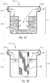
- FIGS. 3A and 3B are perspective views of charge reducing units of the fluid delivery system of FIG. 2B according to examples of the present disclosure.
- the filter unit 112a may include at least one of silica gel 310 ( FIG. 3A ) and a mono-directional membrane 350 ( FIG. 3B ).
- the filter unit 112a may include a silica gel 310 and a housing unit 312 to store the silica gel 310.
- the housing unit 312 may include a removable portion 314 in which the silica gel 310 can be removably stored, and a stationary portion 316 having an inlet 316a and outlet 316b in fluid communication with the removable portion 314 and the silica gel 310 stored therein.
- the silica gel 310 may be replaced as needed.
- the fluid f p from the fluid chamber 111 enters the inlet 316a of the stationary portion 316 of the filter unit 112a. Subsequently, the fluid f p flows into the removable portion 314 of the filter unit 112a and comes in contact with the silica gel 310.
- the silica gel 310 filters the fluid by attracting to its surface solids such as charge directors.
- the filtered fluid f f having a reduced amount and/or no charge directors therein flows out of the outlet 316b of the stationary portion 316 of the filter unit 112a, and into the fluid chamber 111.
- the filtered fluid f f mixes together with the rest of the fluid therein resulting in a reduction of the concentration of the amount of charge directors in the fluid stored in the fluid chamber 111.
- the housing unit 312 may include a mono-directional membrane 350 stored therein in which the mono-directional membrane 350 and/or the housing unit 312, or a portion thereof, is replaceable as illustrated in FIG. 3B .
- the fluid fp from the fluid chamber 111 is directed through the mono-directional membrane 350 in order to remove charge directors therefrom resulting in the filtered fluid f f .
- the filtered fluid f f having a lower concentration of the amount of the charge directors than the fluid in the fluid chamber 111 is directed into the fluid chamber 111.
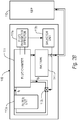
- FIG. 4A is a block diagram illustrating a fluid delivery system of FIG. 2A according to an example of the present disclosure.
- a fluid delivery system 100 includes a fluid chamber 111, a charge reducing unit 112, a charge increasing unit 114, and a charge control unit 113.
- the fluid chamber 111 is configured to store fluid having at least charge directors and a carrier liquid.
- the charge reducing unit 112 is in fluid communication with the fluid chamber 111.
- the charge reducing unit 112 is configured to decrease a charge level of the fluid of the fluid chamber 111.
- the charge reducing unit 112 reduces a concentration of an amount of the charge directors in the fluid of the fluid chamber 111.
- the charge control unit 113 is in communication with the fluid chamber 111, the charge reducing unit 112, and the charge increasing unit 114.
- the charge increasing unit 114 of the fluid delivery system 100 is in fluid communication with the fluid chamber 111 and in communication with the charge control unit 113.
- the charge increasing unit 114 is configured to increase the charge level of the fluid of the fluid chamber 111.
- the charge increasing unit 114 increases a concentration of the amount of the charge directors in the fluid of the fluid chamber 111.
- the charge increasing unit 114 may provide a supplemental fluid 114a ( FIG.
- the charge increasing unit 114 may include the supplemental fluid 114a and a supplemental fluid receptacle 114b configured to removable receive the supplemental fluid 114a as illustrated in FIG. 4B .
- the supplemental fluid 114a may be primarily imaging oil such as ISOPAR, trademarked by Exxon Corporation, having a charge director compound dispersed therein, a toner concentrate 115a having charge directors and toner particles mixed therein, and/or primarily a charge director compound 116a in a solution.
- the supplemental fluid 114a may be replaced as needed.
- the charge control unit 113 is in communication with the fluid chamber 111, the charge reducing unit 112 and the charge increasing unit 114.
- the charge control unit 113 is configured to control the charge level of the fluid based on a detection of at least one fluid parameter corresponding to the charge level of the fluid of the fluid chamber 111.
- FIG. 4B is a partial side view illustrating the fluid delivery system of FIG. 4A according to an example of the present disclosure. Referring to FIGS.
- the charge reducing unit 112 includes a filter unit 112a configured to remove charge directors from the fluid by adsorbtion with the fluid f p entering the filter unit 112a to form a filtered fluid f f having a lower concentration of an amount of charge directors than the fluid in the fluid chamber 111. Subsequently, the filtered fluid f f is directed from the filter unit 112a to the fluid chamber 111.
- the charge control unit 113 includes a fluid parameter detector 113a configured to detect the at least one fluid parameter such as conductivity corresponding to the charge level of the fluid.
- the charge control unit 113 may also include a selector unit 113b configured to place the charge reducing unit 112 such as the filter unit 112a and the charge increasing unit 114 such as the supplemental fluid 114a in or out of fluid communication with the fluid chamber 111 based on the detection of the at least one fluid parameter. For example, when the fluid parameter detector 113a detects the conductivity of the fluid below 70 pS/cm, the selector unit 113b may place the fluid chamber 111 in fluid communication with the supplemental fluid 114a having a higher concentration of the amount of the charge directors than the fluid in the fluid chamber 111 to mix with the fluid therein.
- the selector unit 113b may open an automatic control valve 113d, or the like, disposed between the supplemental fluid 114a and the fluid chamber 111.
- the filtered fluid f f mixes together with the rest of the fluid resulting in a reduction of the concentration of the amount of charge directors in the fluid stored in the fluid chamber 111.
- the supplemental fluid 114a may be primarily imaging oil such as ISOPAR having a charge director compound dispersed therein, a toner concentrate 115a having charge directors and toner particles mixed therein, and/or primarily a charge director compound 116a in solution.
- the supplemental fluid 114a includes the imaging oil having a concentration of an amount of charge directors of approximately 0.075%.
- the fluid delivery system 100 may also include an ink tank 211 configured to receive fluid from the fluid chamber 111 and toner concentrate 115a to form a printing fluid.
- the ink tank 211 may also be in fluid communication with the LEP 110, to provide the printing fluid to a respective BID 130 ( FIG. 1 ) of the LEP 110 to print images therewith.
- the fluid delivery system 100 may include other fluid receptacles 115b in addition to the supplemental fluid receptacle 114b to receivable mount, for example, the toner concentrate 115a.
- the toner concentrate 115a supplies color pigments to the fluid to correspond with a desired color.
- the toner concentrate 115a may include 21.5% solids.
- the selector unit 113b may additionally place the filter unit 112a out of fluid communication with the fluid chamber 111 in response to the detection of the conductivity below 70 pS/cm.
- the selector unit 113b may close an automated control valve 113c, or the like, disposed between the fluid chamber 111 and the charge reducing unit 112.
- the selector unit 113b may select the charge reducing unit 112 to be in fluid communication with the fluid chamber 111 when the conductivity is greater than 110 pS/cm, and select the charge increasing unit 114 to be in fluid communication with the fluid chamber 111 when the conductivity is less than 70 pS/cm.
- the fluid chamber 111 of the fluid delivery system 100 may also be in fluid communication with the LEP 110, for example, through the ink tank 211, to provide the fluid to a respective the BID 130 ( FIG. 1 ).
- FIG. 5 is a flowchart illustrating a method of controlling a charge level of fluid in a fluid chamber of a fluid delivery system 100 according to an example of the present disclosure.
- at least one fluid parameter corresponding to a charge level of a fluid having at least charge directors and carrier liquid in a fluid chamber is detected.
- the at least one parameter may be conductivity and a predetermined range of the conductivity of the fluid may be in a range of 70 pS/cm to 110 pS/cm.
- the charge level of the fluid in the fluid container is controlled by changing a concentration of an amount of the charge directors in the fluid based on the detected fluid parameter.
- a charge control unit may control the charge level of the fluid by selecting at least one of a charge reducing unit and a charge increasing unit to be in fluid communication with the fluid chamber based on the detected at least one fluid parameter of the fluid.
- the charge reducing unit may reduce the concentration of the amount of the charge directors in the fluid and the charge increasing unit may increase the concentration of the amount of the charge directors in the fluid.
- the charge control unit may select the charge reducing unit when the detected fluid parameter is greater than 110 pS/cm and may select the charge increasing unit when the detected fluid parameter is less than 70 pS/cm.
- the concentration of the amount of the charge directors in the fluid may be reduced by a filter unit removing respective charge directors from the fluid by adsorbtion.
- the filter unit 115a may include at least one of a silica gel and a mono-directional membrane ( FIGS. 3A and 3B ).
Landscapes
- Physics & Mathematics (AREA)
- General Physics & Mathematics (AREA)
- Engineering & Computer Science (AREA)
- Microelectronics & Electronic Packaging (AREA)
- Wet Developing In Electrophotography (AREA)
- Ink Jet (AREA)
Description
- Fluid delivery systems for image forming apparatuses such as liquid electrophotography printing apparatuses include providing liquid toner to fluid applicators. Subsequently, the fluid applicators provide the charged liquid toner to an image transfer member that receives images formed by the image forming apparatuses and transfer the images onto substrates such as print media. Generally, the liquid toner includes charge directors to electrically charge the liquid toner.
JPH1165295 relates to controlling a concentration of a charge-control agent in liquid developer, based on a detected toner-image-density by an optical reflection-density-detection means. From a light emission part of a reflection-type photosensor, light irradiates a toner image for optical reflection-density-detection formed on a photoreceptor, and the reflected light from the toner image is received by a light receiving part. Thus, the density of the toner image on the photoreceptor is detected. A control part compares a given reflection-density reference value (a given reference voltage) and the detection value (output voltage) of the sensor. When the detection value is lower than the given reference value, it judges that the density of toner image used for the density detection is higher than a proper density. Accordingly, it transmits a signal to a charge-control-agent supply device and make the device supply the charge control agent to the liquid developer. On the other hand, when the detection value of the sensor is higher than the specific reference value, liquid carrier is supplied to the liquid developer from the liquid-carrier supply device.US5003352 relates to an arrangement to supply a liquid toner dispersion to a printing station of a high speed electrophotographic printing press. A highly concentrated form of the liquid toner dispersion is supplied in a first container. Density sensor in a process tank controls the feed of liquid toner concentrate to the process tank. Liquid level switches in the process tank control toner carrier liquid flow to the process tank. A conductivity sensor monitors the toner in the process tank and controls the flow of liquid charge control agent from tank to the process tank. Flow rate of the liquid toner from the process tank to the printing station of the printing unit is controlled by a sensor, logic circuitry, and motorized adjustable flow valve and flow meter. - The invention is defined by the appended claims.
- Exemplary non-limiting embodiments of the present disclosure are described in the following description, read with reference to the figures attached hereto and do not limit the scope of the claims. In the figures, identical and similar structures, elements or parts thereof that appear in more than one figure are generally labeled with the same or similar references in the figures in which they appear. Dimensions of components and features illustrated in the figures are chosen primarily for convenience and clarity of presentation and are not necessarily to scale. Referring to the attached figures:
-
FIG. 1 is a schematic view illustrating a fluid delivery system in communication with an exemplary liquid electrophotography printing apparatus according to an example of the present disclosure. -
FIG. 2A is a block diagram illustrating a fluid delivery system according to an example of the present disclosure. -
FIG. 2B is a partial side view illustrating the fluid delivery system ofFIG. 2A according to an example of the present disclosure. -
FIGS. 3A and 3B are perspective views of charge reducing units of the fluid delivery system ofFIG. 2B according to examples of the present disclosure. -
FIG. 4A is a block diagram illustrating a fluid delivery system ofFIG. 2A according to an example of the present disclosure. -
FIG. 4B is a partial side view illustrating the fluid delivery system ofFIG. 4A according to an example of the present disclosure. -
FIG. 5 is a flowchart illustrating a method of controlling a charge level of fluid in a fluid chamber of a fluid delivery system according to an example of the present disclosure. - In the following detailed description, reference is made to the accompanying drawings which form a part hereof, and in which is depicted by way of illustration specific embodiments in which the present disclosure may be practiced. It is to be understood that other embodiments may be utilized and structural or logical changes may be made without departing from the scope of the present disclosure. The following detailed description, therefore, is not to be taken in a limiting sense, and the scope of the present disclosure is defined by the appended claims.
- Fluid delivery systems for image forming apparatuses such as liquid electrophotography printing apparatuses provide charged liquid toner including charge directors and a carrier fluid to fluid applicators such as binary ink developers (BIDs) of the liquid electrophotography apparatuses. A fluid chamber receives each of the charge directors and carrier fluid forming the charged liquid toner and subsequently provides the charged liquid toner to a respective BID. The BID provides the charged liquid toner to a latent image on a photo imaging member, which in turn provides the image to an image transfer member such as an image transfer blanket. The image transfer blanket transfers the image onto a substrate such as print media. The fluid delivery system may include multiple fluid chambers in fluid communication with corresponding BIDS in which each fluid chamber with its corresponding BID may correspond to a different color fluid to enable color printing.
- At times, however, a charge level of the liquid toner in the fluid chamber may change in a manner in which the charge level is no longer within a range recommended, for example, for the liquid toner to be sufficiently transferred to and from the intermediate transfer member. The charge level may rise above the recommended range due to, for example, an accumulation of charge directors on the photo imaging member as a result of periodic cleaning processes thereof, an accumulation of charge directors remaining in fluid chamber, and/or printing side effects such as electrical fatigue. Such a rise in charge level may contribute to printing defects resulting in printed images of an inferior image quality. In examples of the present disclosure, a fluid delivery system is disclosed to prevent inferior quality images from being printed and stabilize optical density. A fluid delivery system is disclosed to maintain the charge level of the fluid in the fluid chamber within a predetermined range, for example, by changing a concentration of an amount of charge directors in the fluid. A charge reducing unit is configured to decrease the charge level of the fluid of the fluid chamber and a charge increasing unit is configured to increase the charge level of the fluid based on based on a detection of at least one fluid parameter corresponding to the charge level of the fluid of the fluid chamber.
-
FIG. 1 is a schematic view illustrating a fluid delivery system in communication with an exemplary liquid electrophotography printing apparatus according to an example of the present disclosure. Referring toFIG. 1 , a fluid deliversystem 100 is usable with an image forming apparatus such as a liquid electrophotography printing apparatus (LEP) 110. As illustrated inFIG. 1 , the LEAP 110 includes animage forming unit 120 that receives a substrate S such as a print media from aninput unit 140 and outputs the substrate S to anoutput unit 160. Theimage forming unit 120 includes a photo imaging member (PIP) 180 that defines an outer surface on which images can be formed. The outer surface may be charged with a suitable charger (not illustrated), such as a charge roller, and portions of the outer surface that correspond to features of the image can be selectively discharged by alaser writing unit 119 to form an electrostatic image on the outer surface. - Referring to
FIG. 1 , afluid delivery system 100 may supply fluid such as liquid toner, for example, ElectroInk, trademarked by Hewlett-Packard Company, to fluid development units of theLEP 110 such asBIDs 130. TheBIDs 130 apply the fluid to the electrostatic image to form a fluid image on the outer surface of thePIP 180 to be transferred to an intermediate transfer member (ITM) 150. The ITM 150 is configured to receive the fluid image from thePIP 180, heat the image, and transfer the image to the substrate S. During the transfer from theITM 150 to the substrate S, the substrate S is pinched between theITM 150 and animpression member 190. Once the fluid image has been transferred to the substrate S, the substrate S can be transported to theoutput unit 160. -
FIG. 2A is a block diagram illustrating a fluid delivery system according to an example of the present disclosure. Referring toFIG. 2A , afluid delivery system 100 includes afluid chamber 111, acharge reducing unit 112, and acharge control unit 113. In an example, thefluid delivery system 100 may be disposed within theimage forming apparatus 110. In other examples, thefluid delivery system 100 may be external to theimage forming apparatus 110. In the present example, thefluid chamber 111 is configured to store fluid having at least charge directors and a carrier liquid. In examples, thefluid chamber 111 may be a reservoir, ink tank, or the like. In an example, the fluid may also be supplied to aLEP 110 to print images on a substrate S (FIGS. 1 and2B ) and/or used as a cleaning fluid for thePIP 180, or the like. Thecharge reducing unit 112 is in fluid communication with thefluid chamber 111. Thecharge reducing unit 112 is configured to decrease a charge level of the fluid of thefluid chamber 111. Thecharge control unit 113 is in communication with thefluid chamber 111 and is configured to control the charge level of the fluid based on a detection of at least one fluid parameter corresponding to the charge level of the fluid of thefluid chamber 111. In an example, thecharge reducing unit 112 reduces a concentration of an amount of the charge directors in the fluid of thefluid chamber 111. In an example, the charge directors, that is, charge control agents, may include one or more of lecithin, barium sulfocuccinate, or the like. -
FIG. 2B is a partial side view illustrating the fluid delivery system ofFIG. 2A according to an example of the present disclosure. Referring toFIGS. 2A and2B , in an example, thecharge reducing unit 112 includes afilter unit 112a configured to remove charge directors from the fluid by adsorbtion with the fluid fp entering thefilter unit 112a to form a filtered fluid ff, and provide the filtered fluid ff to thefluid chamber 111. As illustrated inFIG. 2B , thecharge control unit 113 includes afluid parameter detector 113a configured to detect the at least one fluid parameter corresponding to the charge level of the fluid. For example, the at least one fluid parameter may be conductivity, In an example, thecharge control unit 113 may also include aselector unit 113b configured to place thecharge reducing unit 112 such as thefilter unit 112a in or out of fluid communication with thefluid chamber 111 based on the detection of the at least one fluid parameter such as the conductivity of the fluid. - In an example, a predetermined range for the conductivity may be 70 to 110 picoseimens per centimeter (pS/cm). Thus, for example, when the
fluid parameter detector 113a detects the conductivity of the fluid exceeding 110 pS/cm, theselector unit 113b may place thefilter unit 112a in fluid communication with thefluid chamber 111 to reduce the charge level of the fluid. For example, theselector unit 113b may open anautomated control valve 113c, or the like, disposed between thefilter unit 112a and thefluid chamber 111 to enable thefilter unit 112a to remove the charge directors from the fluid passing therethrough. Thefluid parameter detector 113a may be a conductivity sensor disposed on thefluid chamber 111. Thefluid chamber 111 may further include a pump (not illustrated), additional sensors (not illustrated) such as a density sensor, level sensor and temperature sensor, and a fluid temperature controller such as a heater a cooler. As illustrated inFIG. 2B , thefluid delivery system 100 may also include anink tank 211 configured to receive fluid from thefluid chamber 111 andtoner concentrate 115a (FIG. 4B ) to form a printing fluid. Theink tank 211 may also be in fluid communication with theLEP 110, to provide the printing fluid to a respective BID 130 (FIG. 1 ) of theLEP 110 to print images therewith. -
FIGS. 3A and 3B are perspective views of charge reducing units of the fluid delivery system ofFIG. 2B according to examples of the present disclosure. Referring toFIGS. 3A and 3B , thefilter unit 112a may include at least one of silica gel 310 (FIG. 3A ) and a mono-directional membrane 350 (FIG. 3B ). Referring toFIG. 3A , in an example, thefilter unit 112a may include asilica gel 310 and ahousing unit 312 to store thesilica gel 310. Thehousing unit 312 may include aremovable portion 314 in which thesilica gel 310 can be removably stored, and astationary portion 316 having aninlet 316a andoutlet 316b in fluid communication with theremovable portion 314 and thesilica gel 310 stored therein. Thesilica gel 310 may be replaced as needed. In an example, the fluid fp from thefluid chamber 111 enters theinlet 316a of thestationary portion 316 of thefilter unit 112a. Subsequently, the fluid fp flows into theremovable portion 314 of thefilter unit 112a and comes in contact with thesilica gel 310. Thesilica gel 310 filters the fluid by attracting to its surface solids such as charge directors. The filtered fluid ff having a reduced amount and/or no charge directors therein, flows out of theoutlet 316b of thestationary portion 316 of thefilter unit 112a, and into thefluid chamber 111. In thefluid chamber 111, the filtered fluid ff mixes together with the rest of the fluid therein resulting in a reduction of the concentration of the amount of charge directors in the fluid stored in thefluid chamber 111. - In other examples, the
housing unit 312 may include a mono-directional membrane 350 stored therein in which the mono-directional membrane 350 and/or thehousing unit 312, or a portion thereof, is replaceable as illustrated inFIG. 3B . Referring toFIG. 3B , the fluid fp from thefluid chamber 111 is directed through the mono-directional membrane 350 in order to remove charge directors therefrom resulting in the filtered fluid ff. The filtered fluid ff having a lower concentration of the amount of the charge directors than the fluid in thefluid chamber 111 is directed into thefluid chamber 111. -
FIG. 4A is a block diagram illustrating a fluid delivery system ofFIG. 2A according to an example of the present disclosure. Referring toFIG. 4A , in an example, afluid delivery system 100 includes afluid chamber 111, acharge reducing unit 112, acharge increasing unit 114, and acharge control unit 113. In the present example, thefluid chamber 111 is configured to store fluid having at least charge directors and a carrier liquid. Thecharge reducing unit 112 is in fluid communication with thefluid chamber 111. Thecharge reducing unit 112 is configured to decrease a charge level of the fluid of thefluid chamber 111. In an example, thecharge reducing unit 112 reduces a concentration of an amount of the charge directors in the fluid of thefluid chamber 111. Thecharge control unit 113 is in communication with thefluid chamber 111, thecharge reducing unit 112, and thecharge increasing unit 114. - Referring to
FIG, 4A , in an example, thecharge increasing unit 114 of thefluid delivery system 100 is in fluid communication with thefluid chamber 111 and in communication with thecharge control unit 113. In an example, thecharge increasing unit 114 is configured to increase the charge level of the fluid of thefluid chamber 111. In an example, thecharge increasing unit 114 increases a concentration of the amount of the charge directors in the fluid of thefluid chamber 111. For example, thecharge increasing unit 114 may provide asupplemental fluid 114a (FIG. 4B ) to the fluid of thefluid chamber 111 such that the concentration of the amount of charge directors of thesupplemental fluid 114a is greater than the concentration of the amount of the charge directors of the fluid in thefluid chamber 111 at the time of the detection of the at least one fluid parameter, In an example, thecharge increasing unit 114 may include thesupplemental fluid 114a and a supplementalfluid receptacle 114b configured to removable receive thesupplemental fluid 114a as illustrated inFIG. 4B . In an example, thesupplemental fluid 114a may be primarily imaging oil such as ISOPAR, trademarked by Exxon Corporation, having a charge director compound dispersed therein, atoner concentrate 115a having charge directors and toner particles mixed therein, and/or primarily acharge director compound 116a in a solution. Thesupplemental fluid 114a may be replaced as needed. - Referring to
FIG. 4A , in an example, thecharge control unit 113 is in communication with thefluid chamber 111, thecharge reducing unit 112 and thecharge increasing unit 114. In the present example, thecharge control unit 113 is configured to control the charge level of the fluid based on a detection of at least one fluid parameter corresponding to the charge level of the fluid of thefluid chamber 111.FIG. 4B is a partial side view illustrating the fluid delivery system ofFIG. 4A according to an example of the present disclosure. Referring toFIGS. 4A and4B , in an example, thecharge reducing unit 112 includes afilter unit 112a configured to remove charge directors from the fluid by adsorbtion with the fluid fp entering thefilter unit 112a to form a filtered fluid ff having a lower concentration of an amount of charge directors than the fluid in thefluid chamber 111. Subsequently, the filtered fluid ff is directed from thefilter unit 112a to thefluid chamber 111. As illustrated inFIG. 4B , thecharge control unit 113 includes afluid parameter detector 113a configured to detect the at least one fluid parameter such as conductivity corresponding to the charge level of the fluid. - Referring to
FIG. 4B , thecharge control unit 113 may also include aselector unit 113b configured to place thecharge reducing unit 112 such as thefilter unit 112a and thecharge increasing unit 114 such as thesupplemental fluid 114a in or out of fluid communication with thefluid chamber 111 based on the detection of the at least one fluid parameter. For example, when thefluid parameter detector 113a detects the conductivity of the fluid below 70 pS/cm, theselector unit 113b may place thefluid chamber 111 in fluid communication with thesupplemental fluid 114a having a higher concentration of the amount of the charge directors than the fluid in thefluid chamber 111 to mix with the fluid therein. For example, theselector unit 113b may open anautomatic control valve 113d, or the like, disposed between thesupplemental fluid 114a and thefluid chamber 111. Thus, in thefluid chamber 111, the filtered fluid ff mixes together with the rest of the fluid resulting in a reduction of the concentration of the amount of charge directors in the fluid stored in thefluid chamber 111. Accordingly, thesupplemental fluid 114a may be primarily imaging oil such as ISOPAR having a charge director compound dispersed therein, atoner concentrate 115a having charge directors and toner particles mixed therein, and/or primarily acharge director compound 116a in solution. In an example, thesupplemental fluid 114a includes the imaging oil having a concentration of an amount of charge directors of approximately 0.075%. - Referring to
FIG. 4B , thefluid delivery system 100 may also include anink tank 211 configured to receive fluid from thefluid chamber 111 andtoner concentrate 115a to form a printing fluid. Theink tank 211 may also be in fluid communication with theLEP 110, to provide the printing fluid to a respective BID 130 (FIG. 1 ) of theLEP 110 to print images therewith. In an example, thefluid delivery system 100 may include otherfluid receptacles 115b in addition to thesupplemental fluid receptacle 114b to receivable mount, for example, thetoner concentrate 115a. In an example, thetoner concentrate 115a supplies color pigments to the fluid to correspond with a desired color. In an example, thetoner concentrate 115a may include 21.5% solids. - In other examples, the
selector unit 113b may additionally place thefilter unit 112a out of fluid communication with thefluid chamber 111 in response to the detection of the conductivity below 70 pS/cm. For example, theselector unit 113b may close anautomated control valve 113c, or the like, disposed between thefluid chamber 111 and thecharge reducing unit 112. In an example, theselector unit 113b may select thecharge reducing unit 112 to be in fluid communication with thefluid chamber 111 when the conductivity is greater than 110 pS/cm, and select thecharge increasing unit 114 to be in fluid communication with thefluid chamber 111 when the conductivity is less than 70 pS/cm. As illustrated inFIG. 4B , thefluid chamber 111 of thefluid delivery system 100 may also be in fluid communication with theLEP 110, for example, through theink tank 211, to provide the fluid to a respective the BID 130 (FIG. 1 ). -
FIG. 5 is a flowchart illustrating a method of controlling a charge level of fluid in a fluid chamber of afluid delivery system 100 according to an example of the present disclosure. Referring toFIGS. 4A ,4B and5 , inblock 510, at least one fluid parameter corresponding to a charge level of a fluid having at least charge directors and carrier liquid in a fluid chamber is detected. In an example, the at least one parameter may be conductivity and a predetermined range of the conductivity of the fluid may be in a range of 70 pS/cm to 110 pS/cm. - In
block 520, the charge level of the fluid in the fluid container is controlled by changing a concentration of an amount of the charge directors in the fluid based on the detected fluid parameter. For example, a charge control unit may control the charge level of the fluid by selecting at least one of a charge reducing unit and a charge increasing unit to be in fluid communication with the fluid chamber based on the detected at least one fluid parameter of the fluid. In an example, the charge reducing unit may reduce the concentration of the amount of the charge directors in the fluid and the charge increasing unit may increase the concentration of the amount of the charge directors in the fluid. In an example, the charge control unit may select the charge reducing unit when the detected fluid parameter is greater than 110 pS/cm and may select the charge increasing unit when the detected fluid parameter is less than 70 pS/cm. The concentration of the amount of the charge directors in the fluid may be reduced by a filter unit removing respective charge directors from the fluid by adsorbtion. In examples, thefilter unit 115a may include at least one of a silica gel and a mono-directional membrane (FIGS. 3A and 3B ). - The present disclosure has been described using non-limiting detailed descriptions of example embodiments thereof that are provided by way of example and are not intended to limit the scope of the present disclosure. It should be understood that features and/or operations described with respect to one example may be used with other examples and that not all examples of the present disclosure have all of the features and/or operations illustrated in a particular figure or described with respect to one of the embodiments. Variations of embodiments described will occur to persons of the art. Furthermore, the terms "comprises," "include," "have" and their conjugates, shall mean, when used in the present disclosure and/or claims, "including but not necessarily limited to."
- It is noted that some of the above described embodiments may describe examples contemplated by the inventors and therefore may include structure, acts or details of structures and acts that may not be essential to the present disclosure and which are described as examples. Structure and acts described herein are replaceable by equivalents, which perform the same function, even if the structure or acts are different, as known in the art. Therefore, the scope of the present disclosure is limited only by the elements and limitations as used in the claims.
Claims (13)
- A fluid delivery system (100) usable with a liquid electrophotography printing apparatus (110), the system (100) comprising:a fluid chamber (111) configured to store fluid having at least charge directors and a carrier liquid;a charge reducing unit (112) in communication with the fluid chamber (111), the charge reducing unit (112) configured to decrease a charge level of the fluid of the fluid chamber (111); anda charge control unit (113) in communication with the fluid chamber (111) and the charge reducing unit (112), the charge control unit (113) configured to control the charge level of the fluid based on a detection of at least one fluid parameter corresponding to the charge level of the fluid of the fluid chamber (111), whereinthe charge reducing unit (112) is configured to reduce a concentration of an amount of the charge directors in the fluid of the fluid chamber (111), andthe charge reducing unit (112) comprises a filter unit (112a) configured to remove charge directors from the fluid by adsorbtion to form a filtered fluid and provide the filtered fluid to the fluid chamber (111).
- The system (100) according to claim 1, wherein the filter unit (112a) comprises at least one of a silica gel (310) and a mono-directional membrane (350).
- The system (100) according to claim 1, wherein the charge control unit (113) comprises:a fluid parameter detector (113a) configured to detect the at least one fluid parameter corresponding to the charge level of the fluid.
- The system (100) according to claim 1, further comprising:a charge increasing unit (114) configured to increase the charge level of the fluid of the fluid chamber (111) by providing a supplemental fluid to the fluid of the fluid chamber (111) such that the concentration of the amount of the charge directors of the supplemental fluid is greater than the concentration of the amount of the charge directors of the fluid at the time of the detection of the at least one fluid parameter.
- The system (100) according to claim 3, further comprising:an ink tank (211) configured to receive fluid from the fluid chamber (111) and toner concentrate to form a printing fluid, wherein the printing fluid is provided from the ink tank (211) to the liquid electrophotography printing apparatus (110) to enable images to be formed on a substrate.
- The system (100) according to claim 4, wherein the charge control unit (113) further comprises:a selector unit (113b) configured to select at least one of the charge reducing unit (112) and the charge increasing unit (114) to be in fluid communication with the fluid chamber (111) based on the detection of the at least one fluid parameter.
- The system (100) according to claim 6, wherein the at least one fluid parameter is conductivity.
- The system (100) according to claim 7, wherein the selector unit (113b) is configured to select the charge reducing unit (112) when the conductivity is greater than 110 pS/cm and select the charge increasing unit (114) when the conductivity is less than 70 pS/cm.
- A method of controlling a charge level of fluid in a fluid chamber (111) of a fluid delivery system (100), the method comprising:detecting at least one fluid parameter corresponding to a charge level of a fluid having at least charge directors and carrier liquid in a fluid chamber (111); andcontrolling the charge level of the fluid in the fluid chamber (111) by changing a concentration of an amount of the charge directors in the fluid based on the detected fluid parameter, whereincontrolling the charge level includes reducing, by a charge reducing unit (112), the concentration of the amount of charge directors in the fluid, andthe concentration of the amount of the charge directors in the fluid is reduced by a filter unit (112a) removing respective charge directors from the fluid.
- The method according to claim 9, wherein the at least one fluid parameter is conductivity.
- The method according to claim 10, wherein a charge control unit (113) controls the charge level of the fluid by selecting at least one of the charge reducing unit (112) and a charge increasing unit (114) to be in fluid communication with the fluid chamber (111) based on the detected at least one fluid parameter of the fluid, wherein the charge increasing unit (114) increases the concentration of the amount of charge directors in the fluid.
- The method according to claim 11, wherein the charge control unit (113) selects the charge reducing unit (112) when the detected fluid parameter is greater than 110 pS/cm and selects the charge increasing unit (114) when the detected fluid parameter is less than 70 pS/cm.
- The method according to claim 11, wherein the filter unit (112a) includes at least one of a silica gel (310) and a mono-directional membrane (350).
Applications Claiming Priority (1)
| Application Number | Priority Date | Filing Date | Title |
|---|---|---|---|
| PCT/US2010/046169 WO2012023946A1 (en) | 2010-08-20 | 2010-08-20 | Fluid delivery system and method thereof |
Publications (3)
| Publication Number | Publication Date |
|---|---|
| EP2605914A1 EP2605914A1 (en) | 2013-06-26 |
| EP2605914A4 EP2605914A4 (en) | 2017-04-26 |
| EP2605914B1 true EP2605914B1 (en) | 2018-02-21 |
Family
ID=45605375
Family Applications (1)
| Application Number | Title | Priority Date | Filing Date |
|---|---|---|---|
| EP10856244.8A Not-in-force EP2605914B1 (en) | 2010-08-20 | 2010-08-20 | Fluid delivery system and method thereof |
Country Status (5)
| Country | Link |
|---|---|
| US (1) | US8983321B2 (en) |
| EP (1) | EP2605914B1 (en) |
| CN (1) | CN103052509B (en) |
| BR (1) | BR112013003824A2 (en) |
| WO (1) | WO2012023946A1 (en) |
Cited By (1)
| Publication number | Priority date | Publication date | Assignee | Title |
|---|---|---|---|---|
| WO2021211101A1 (en) * | 2020-04-14 | 2021-10-21 | Hewlett-Packard Development Company, L.P. | Force adjustment arrangement |
Families Citing this family (2)
| Publication number | Priority date | Publication date | Assignee | Title |
|---|---|---|---|---|
| JP7066406B2 (en) * | 2017-12-28 | 2022-05-13 | キヤノン株式会社 | Recording device, recording method, and program |
| WO2019177568A1 (en) * | 2018-03-12 | 2019-09-19 | Hewlett-Packard Development Company, L.P. | Non-nucleation fluid actuator measurements |
Family Cites Families (8)
| Publication number | Priority date | Publication date | Assignee | Title |
|---|---|---|---|---|
| US4860924A (en) * | 1986-02-14 | 1989-08-29 | Savin Corporation | Liquid developer charge director control |
| US5231454A (en) | 1989-05-15 | 1993-07-27 | Spectrum Sciences B.V. | Charge director replenishment system and method for a liquid toner developing apparatus |
| US5003352A (en) * | 1989-10-24 | 1991-03-26 | Am International, Inc. | Liquid toner supply system and method |
| US5278615A (en) * | 1990-07-23 | 1994-01-11 | Spectrum Sciences B.V. | Liquid toner imaging system |
| JPH0915982A (en) * | 1995-06-28 | 1997-01-17 | Minolta Co Ltd | Monitoring device for physical property of liquid |
| JPH1165295A (en) * | 1997-08-15 | 1999-03-05 | Minolta Co Ltd | Image forming device |
| US7343121B2 (en) * | 2005-12-21 | 2008-03-11 | Eastman Kodak Company | Addition of liquid charge control agents to toner in toner development stations of electrographic reproduction apparatus |
| JP5240541B2 (en) | 2007-02-26 | 2013-07-17 | 株式会社リコー | Image forming apparatus |
-
2010
- 2010-08-20 US US13/816,467 patent/US8983321B2/en active Active
- 2010-08-20 EP EP10856244.8A patent/EP2605914B1/en not_active Not-in-force
- 2010-08-20 BR BR112013003824A patent/BR112013003824A2/en active Search and Examination
- 2010-08-20 CN CN201080068676.4A patent/CN103052509B/en not_active Expired - Fee Related
- 2010-08-20 WO PCT/US2010/046169 patent/WO2012023946A1/en not_active Ceased
Non-Patent Citations (1)
| Title |
|---|
| None * |
Cited By (2)
| Publication number | Priority date | Publication date | Assignee | Title |
|---|---|---|---|---|
| WO2021211101A1 (en) * | 2020-04-14 | 2021-10-21 | Hewlett-Packard Development Company, L.P. | Force adjustment arrangement |
| US12498653B2 (en) | 2020-04-14 | 2025-12-16 | Hewlett-Packard Development Company, L.P. | Force adjustment arrangement |
Also Published As
| Publication number | Publication date |
|---|---|
| EP2605914A1 (en) | 2013-06-26 |
| EP2605914A4 (en) | 2017-04-26 |
| US20130148989A1 (en) | 2013-06-13 |
| US8983321B2 (en) | 2015-03-17 |
| CN103052509B (en) | 2015-04-22 |
| CN103052509A (en) | 2013-04-17 |
| BR112013003824A2 (en) | 2016-06-28 |
| WO2012023946A1 (en) | 2012-02-23 |
Similar Documents
| Publication | Publication Date | Title |
|---|---|---|
| US5003352A (en) | Liquid toner supply system and method | |
| CN101943875B (en) | Developing device, process cartridge and image forming apparatus | |
| CN101504525B (en) | Image forming apparatus and image forming method | |
| AU2009200904A1 (en) | Device and method for electrophoretic liquid development | |
| US9696654B2 (en) | Image forming apparatus comprising image density detector and toner concentration detector | |
| CN101556449B (en) | imaging device | |
| US20140270818A1 (en) | Image forming apparatus | |
| US5722017A (en) | Liquid developing material replenishment system and method | |
| JPH10104954A (en) | Developing system, developing device and printing method for electrostatic copying and printing machine | |
| US8879939B2 (en) | Method to operate a digital printer to print a recording material, and associated digital printer with mixing container | |
| US8983321B2 (en) | Fluid delivery system and method thereof | |
| US5923356A (en) | Liquid developing material replenishment control system | |
| US20070047985A1 (en) | Development System and Image Forming Apparatus Using the Same | |
| JP2003167442A (en) | A toner recycling control method for electrophotographic equipment using a highly viscous liquid developer | |
| US20060232615A1 (en) | Device and method for electrophoretic liquid development | |
| KR20010012518A (en) | Color control system for electrographic printer | |
| US9341980B2 (en) | Process unit and image forming apparatus | |
| JP6167662B2 (en) | Image forming apparatus and consumable management system | |
| US8078086B2 (en) | Liquid developer transport device and image forming apparatus | |
| US20090028610A1 (en) | Electrophotographic Printing | |
| JP2007057772A (en) | Development system | |
| EP1304600B1 (en) | Systems and methods for liquid immersion development | |
| JP5277139B2 (en) | Extraction apparatus and image forming apparatus incorporating the extraction apparatus | |
| JP4780286B2 (en) | Development system | |
| JP3515218B2 (en) | Wet image forming device |
Legal Events
| Date | Code | Title | Description |
|---|---|---|---|
| PUAI | Public reference made under article 153(3) epc to a published international application that has entered the european phase |
Free format text: ORIGINAL CODE: 0009012 |
|
| 17P | Request for examination filed |
Effective date: 20130124 |
|
| AK | Designated contracting states |
Kind code of ref document: A1 Designated state(s): AL AT BE BG CH CY CZ DE DK EE ES FI FR GB GR HR HU IE IS IT LI LT LU LV MC MK MT NL NO PL PT RO SE SI SK SM TR |
|
| DAX | Request for extension of the european patent (deleted) | ||
| RAP1 | Party data changed (applicant data changed or rights of an application transferred) |
Owner name: HEWLETT-PACKARD INDIGO B.V. |
|
| RA4 | Supplementary search report drawn up and despatched (corrected) |
Effective date: 20170329 |
|
| RIC1 | Information provided on ipc code assigned before grant |
Ipc: G03G 15/10 20060101ALI20170323BHEP Ipc: G03G 15/00 20060101ALI20170323BHEP Ipc: B41J 2/18 20060101AFI20170323BHEP Ipc: B41J 2/17 20060101ALI20170323BHEP Ipc: B41J 2/185 20060101ALI20170323BHEP |
|
| GRAP | Despatch of communication of intention to grant a patent |
Free format text: ORIGINAL CODE: EPIDOSNIGR1 |
|
| INTG | Intention to grant announced |
Effective date: 20171129 |
|
| RAP1 | Party data changed (applicant data changed or rights of an application transferred) |
Owner name: HP INDIGO B.V. |
|
| RIN1 | Information on inventor provided before grant (corrected) |
Inventor name: SHKURI, KOBI Inventor name: KLEIN, NAVA Inventor name: BACHAR, EYAL Inventor name: SILCOFF, ELLIAD |
|
| GRAS | Grant fee paid |
Free format text: ORIGINAL CODE: EPIDOSNIGR3 |
|
| GRAA | (expected) grant |
Free format text: ORIGINAL CODE: 0009210 |
|
| AK | Designated contracting states |
Kind code of ref document: B1 Designated state(s): AL AT BE BG CH CY CZ DE DK EE ES FI FR GB GR HR HU IE IS IT LI LT LU LV MC MK MT NL NO PL PT RO SE SI SK SM TR |
|
| REG | Reference to a national code |
Ref country code: GB Ref legal event code: FG4D |
|
| REG | Reference to a national code |
Ref country code: CH Ref legal event code: EP |
|
| REG | Reference to a national code |
Ref country code: AT Ref legal event code: REF Ref document number: 971274 Country of ref document: AT Kind code of ref document: T Effective date: 20180315 |
|
| REG | Reference to a national code |
Ref country code: IE Ref legal event code: FG4D |
|
| REG | Reference to a national code |
Ref country code: DE Ref legal event code: R096 Ref document number: 602010048737 Country of ref document: DE |
|
| REG | Reference to a national code |
Ref country code: NL Ref legal event code: MP Effective date: 20180221 |
|
| REG | Reference to a national code |
Ref country code: LT Ref legal event code: MG4D |
|
| REG | Reference to a national code |
Ref country code: AT Ref legal event code: MK05 Ref document number: 971274 Country of ref document: AT Kind code of ref document: T Effective date: 20180221 |
|
| REG | Reference to a national code |
Ref country code: FR Ref legal event code: PLFP Year of fee payment: 9 |
|
| PG25 | Lapsed in a contracting state [announced via postgrant information from national office to epo] |
Ref country code: ES Free format text: LAPSE BECAUSE OF FAILURE TO SUBMIT A TRANSLATION OF THE DESCRIPTION OR TO PAY THE FEE WITHIN THE PRESCRIBED TIME-LIMIT Effective date: 20180221 Ref country code: CY Free format text: LAPSE BECAUSE OF FAILURE TO SUBMIT A TRANSLATION OF THE DESCRIPTION OR TO PAY THE FEE WITHIN THE PRESCRIBED TIME-LIMIT Effective date: 20180221 Ref country code: LT Free format text: LAPSE BECAUSE OF FAILURE TO SUBMIT A TRANSLATION OF THE DESCRIPTION OR TO PAY THE FEE WITHIN THE PRESCRIBED TIME-LIMIT Effective date: 20180221 Ref country code: NL Free format text: LAPSE BECAUSE OF FAILURE TO SUBMIT A TRANSLATION OF THE DESCRIPTION OR TO PAY THE FEE WITHIN THE PRESCRIBED TIME-LIMIT Effective date: 20180221 Ref country code: FI Free format text: LAPSE BECAUSE OF FAILURE TO SUBMIT A TRANSLATION OF THE DESCRIPTION OR TO PAY THE FEE WITHIN THE PRESCRIBED TIME-LIMIT Effective date: 20180221 Ref country code: NO Free format text: LAPSE BECAUSE OF FAILURE TO SUBMIT A TRANSLATION OF THE DESCRIPTION OR TO PAY THE FEE WITHIN THE PRESCRIBED TIME-LIMIT Effective date: 20180521 Ref country code: HR Free format text: LAPSE BECAUSE OF FAILURE TO SUBMIT A TRANSLATION OF THE DESCRIPTION OR TO PAY THE FEE WITHIN THE PRESCRIBED TIME-LIMIT Effective date: 20180221 |
|
| PG25 | Lapsed in a contracting state [announced via postgrant information from national office to epo] |
Ref country code: AT Free format text: LAPSE BECAUSE OF FAILURE TO SUBMIT A TRANSLATION OF THE DESCRIPTION OR TO PAY THE FEE WITHIN THE PRESCRIBED TIME-LIMIT Effective date: 20180221 Ref country code: GR Free format text: LAPSE BECAUSE OF FAILURE TO SUBMIT A TRANSLATION OF THE DESCRIPTION OR TO PAY THE FEE WITHIN THE PRESCRIBED TIME-LIMIT Effective date: 20180522 Ref country code: BG Free format text: LAPSE BECAUSE OF FAILURE TO SUBMIT A TRANSLATION OF THE DESCRIPTION OR TO PAY THE FEE WITHIN THE PRESCRIBED TIME-LIMIT Effective date: 20180521 Ref country code: SE Free format text: LAPSE BECAUSE OF FAILURE TO SUBMIT A TRANSLATION OF THE DESCRIPTION OR TO PAY THE FEE WITHIN THE PRESCRIBED TIME-LIMIT Effective date: 20180221 Ref country code: LV Free format text: LAPSE BECAUSE OF FAILURE TO SUBMIT A TRANSLATION OF THE DESCRIPTION OR TO PAY THE FEE WITHIN THE PRESCRIBED TIME-LIMIT Effective date: 20180221 |
|
| PG25 | Lapsed in a contracting state [announced via postgrant information from national office to epo] |
Ref country code: RO Free format text: LAPSE BECAUSE OF FAILURE TO SUBMIT A TRANSLATION OF THE DESCRIPTION OR TO PAY THE FEE WITHIN THE PRESCRIBED TIME-LIMIT Effective date: 20180221 Ref country code: AL Free format text: LAPSE BECAUSE OF FAILURE TO SUBMIT A TRANSLATION OF THE DESCRIPTION OR TO PAY THE FEE WITHIN THE PRESCRIBED TIME-LIMIT Effective date: 20180221 Ref country code: PL Free format text: LAPSE BECAUSE OF FAILURE TO SUBMIT A TRANSLATION OF THE DESCRIPTION OR TO PAY THE FEE WITHIN THE PRESCRIBED TIME-LIMIT Effective date: 20180221 Ref country code: EE Free format text: LAPSE BECAUSE OF FAILURE TO SUBMIT A TRANSLATION OF THE DESCRIPTION OR TO PAY THE FEE WITHIN THE PRESCRIBED TIME-LIMIT Effective date: 20180221 Ref country code: IT Free format text: LAPSE BECAUSE OF FAILURE TO SUBMIT A TRANSLATION OF THE DESCRIPTION OR TO PAY THE FEE WITHIN THE PRESCRIBED TIME-LIMIT Effective date: 20180221 |
|
| REG | Reference to a national code |
Ref country code: DE Ref legal event code: R097 Ref document number: 602010048737 Country of ref document: DE |
|
| PG25 | Lapsed in a contracting state [announced via postgrant information from national office to epo] |
Ref country code: DK Free format text: LAPSE BECAUSE OF FAILURE TO SUBMIT A TRANSLATION OF THE DESCRIPTION OR TO PAY THE FEE WITHIN THE PRESCRIBED TIME-LIMIT Effective date: 20180221 Ref country code: SM Free format text: LAPSE BECAUSE OF FAILURE TO SUBMIT A TRANSLATION OF THE DESCRIPTION OR TO PAY THE FEE WITHIN THE PRESCRIBED TIME-LIMIT Effective date: 20180221 Ref country code: CZ Free format text: LAPSE BECAUSE OF FAILURE TO SUBMIT A TRANSLATION OF THE DESCRIPTION OR TO PAY THE FEE WITHIN THE PRESCRIBED TIME-LIMIT Effective date: 20180221 Ref country code: SK Free format text: LAPSE BECAUSE OF FAILURE TO SUBMIT A TRANSLATION OF THE DESCRIPTION OR TO PAY THE FEE WITHIN THE PRESCRIBED TIME-LIMIT Effective date: 20180221 |
|
| PLBE | No opposition filed within time limit |
Free format text: ORIGINAL CODE: 0009261 |
|
| STAA | Information on the status of an ep patent application or granted ep patent |
Free format text: STATUS: NO OPPOSITION FILED WITHIN TIME LIMIT |
|
| 26N | No opposition filed |
Effective date: 20181122 |
|
| PG25 | Lapsed in a contracting state [announced via postgrant information from national office to epo] |
Ref country code: SI Free format text: LAPSE BECAUSE OF FAILURE TO SUBMIT A TRANSLATION OF THE DESCRIPTION OR TO PAY THE FEE WITHIN THE PRESCRIBED TIME-LIMIT Effective date: 20180221 |
|
| PG25 | Lapsed in a contracting state [announced via postgrant information from national office to epo] |
Ref country code: MC Free format text: LAPSE BECAUSE OF FAILURE TO SUBMIT A TRANSLATION OF THE DESCRIPTION OR TO PAY THE FEE WITHIN THE PRESCRIBED TIME-LIMIT Effective date: 20180221 |
|
| REG | Reference to a national code |
Ref country code: CH Ref legal event code: PL |
|
| PG25 | Lapsed in a contracting state [announced via postgrant information from national office to epo] |
Ref country code: CH Free format text: LAPSE BECAUSE OF NON-PAYMENT OF DUE FEES Effective date: 20180831 Ref country code: LU Free format text: LAPSE BECAUSE OF NON-PAYMENT OF DUE FEES Effective date: 20180820 Ref country code: LI Free format text: LAPSE BECAUSE OF NON-PAYMENT OF DUE FEES Effective date: 20180831 |
|
| REG | Reference to a national code |
Ref country code: BE Ref legal event code: MM Effective date: 20180831 |
|
| REG | Reference to a national code |
Ref country code: IE Ref legal event code: MM4A |
|
| PG25 | Lapsed in a contracting state [announced via postgrant information from national office to epo] |
Ref country code: IE Free format text: LAPSE BECAUSE OF NON-PAYMENT OF DUE FEES Effective date: 20180820 |
|
| PG25 | Lapsed in a contracting state [announced via postgrant information from national office to epo] |
Ref country code: BE Free format text: LAPSE BECAUSE OF NON-PAYMENT OF DUE FEES Effective date: 20180831 |
|
| PG25 | Lapsed in a contracting state [announced via postgrant information from national office to epo] |
Ref country code: MT Free format text: LAPSE BECAUSE OF NON-PAYMENT OF DUE FEES Effective date: 20180820 |
|
| PG25 | Lapsed in a contracting state [announced via postgrant information from national office to epo] |
Ref country code: TR Free format text: LAPSE BECAUSE OF FAILURE TO SUBMIT A TRANSLATION OF THE DESCRIPTION OR TO PAY THE FEE WITHIN THE PRESCRIBED TIME-LIMIT Effective date: 20180221 |
|
| PG25 | Lapsed in a contracting state [announced via postgrant information from national office to epo] |
Ref country code: PT Free format text: LAPSE BECAUSE OF FAILURE TO SUBMIT A TRANSLATION OF THE DESCRIPTION OR TO PAY THE FEE WITHIN THE PRESCRIBED TIME-LIMIT Effective date: 20180221 Ref country code: HU Free format text: LAPSE BECAUSE OF FAILURE TO SUBMIT A TRANSLATION OF THE DESCRIPTION OR TO PAY THE FEE WITHIN THE PRESCRIBED TIME-LIMIT; INVALID AB INITIO Effective date: 20100820 |
|
| PG25 | Lapsed in a contracting state [announced via postgrant information from national office to epo] |
Ref country code: MK Free format text: LAPSE BECAUSE OF NON-PAYMENT OF DUE FEES Effective date: 20180221 |
|
| PG25 | Lapsed in a contracting state [announced via postgrant information from national office to epo] |
Ref country code: IS Free format text: LAPSE BECAUSE OF FAILURE TO SUBMIT A TRANSLATION OF THE DESCRIPTION OR TO PAY THE FEE WITHIN THE PRESCRIBED TIME-LIMIT Effective date: 20180621 |
|
| PGFP | Annual fee paid to national office [announced via postgrant information from national office to epo] |
Ref country code: FR Payment date: 20200721 Year of fee payment: 11 Ref country code: GB Payment date: 20200722 Year of fee payment: 11 |
|
| GBPC | Gb: european patent ceased through non-payment of renewal fee |
Effective date: 20210820 |
|
| PG25 | Lapsed in a contracting state [announced via postgrant information from national office to epo] |
Ref country code: GB Free format text: LAPSE BECAUSE OF NON-PAYMENT OF DUE FEES Effective date: 20210820 Ref country code: FR Free format text: LAPSE BECAUSE OF NON-PAYMENT OF DUE FEES Effective date: 20210831 |
|
| PGFP | Annual fee paid to national office [announced via postgrant information from national office to epo] |
Ref country code: DE Payment date: 20230720 Year of fee payment: 14 |
|
| REG | Reference to a national code |
Ref country code: DE Ref legal event code: R119 Ref document number: 602010048737 Country of ref document: DE |
|
| PG25 | Lapsed in a contracting state [announced via postgrant information from national office to epo] |
Ref country code: DE Free format text: LAPSE BECAUSE OF NON-PAYMENT OF DUE FEES Effective date: 20250301 |