EP2605848B1 - Fluid filter device - Google Patents
Fluid filter device Download PDFInfo
- Publication number
- EP2605848B1 EP2605848B1 EP11817604.9A EP11817604A EP2605848B1 EP 2605848 B1 EP2605848 B1 EP 2605848B1 EP 11817604 A EP11817604 A EP 11817604A EP 2605848 B1 EP2605848 B1 EP 2605848B1
- Authority
- EP
- European Patent Office
- Prior art keywords
- fluid
- porous section
- filter device
- section
- fluid filter
- Prior art date
- Legal status (The legal status is an assumption and is not a legal conclusion. Google has not performed a legal analysis and makes no representation as to the accuracy of the status listed.)
- Expired - Fee Related
Links
- 239000012530 fluid Substances 0.000 title claims description 198
- 238000004140 cleaning Methods 0.000 claims description 38
- 238000001914 filtration Methods 0.000 claims description 9
- 239000002245 particle Substances 0.000 claims description 5
- 230000009471 action Effects 0.000 claims description 4
- 239000010419 fine particle Substances 0.000 claims description 4
- 238000011001 backwashing Methods 0.000 claims description 3
- 238000004891 communication Methods 0.000 claims description 3
- 230000004931 aggregating effect Effects 0.000 claims 2
- 230000003247 decreasing effect Effects 0.000 claims 1
- 230000005855 radiation Effects 0.000 description 28
- XLYOFNOQVPJJNP-UHFFFAOYSA-N water Substances O XLYOFNOQVPJJNP-UHFFFAOYSA-N 0.000 description 20
- 239000000463 material Substances 0.000 description 12
- 238000000926 separation method Methods 0.000 description 9
- 238000013461 design Methods 0.000 description 4
- 238000009434 installation Methods 0.000 description 4
- 241000894007 species Species 0.000 description 4
- 239000003651 drinking water Substances 0.000 description 3
- 210000002969 egg yolk Anatomy 0.000 description 3
- 230000005484 gravity Effects 0.000 description 3
- 239000010841 municipal wastewater Substances 0.000 description 3
- 241000894006 Bacteria Species 0.000 description 2
- 238000013459 approach Methods 0.000 description 2
- 238000003491 array Methods 0.000 description 2
- 235000020188 drinking water Nutrition 0.000 description 2
- 230000000694 effects Effects 0.000 description 2
- 229920001971 elastomer Polymers 0.000 description 2
- 239000000806 elastomer Substances 0.000 description 2
- 230000036541 health Effects 0.000 description 2
- 230000006872 improvement Effects 0.000 description 2
- 238000002955 isolation Methods 0.000 description 2
- 239000007788 liquid Substances 0.000 description 2
- 238000012423 maintenance Methods 0.000 description 2
- 244000005700 microbiome Species 0.000 description 2
- 238000012986 modification Methods 0.000 description 2
- 230000004048 modification Effects 0.000 description 2
- 238000007789 sealing Methods 0.000 description 2
- 239000007787 solid Substances 0.000 description 2
- 238000004065 wastewater treatment Methods 0.000 description 2
- 229910001369 Brass Inorganic materials 0.000 description 1
- 230000002411 adverse Effects 0.000 description 1
- 235000012206 bottled water Nutrition 0.000 description 1
- 239000010951 brass Substances 0.000 description 1
- 230000008859 change Effects 0.000 description 1
- 239000011362 coarse particle Substances 0.000 description 1
- 230000002860 competitive effect Effects 0.000 description 1
- 230000001627 detrimental effect Effects 0.000 description 1
- 238000011161 development Methods 0.000 description 1
- 238000000605 extraction Methods 0.000 description 1
- 239000013505 freshwater Substances 0.000 description 1
- 238000000034 method Methods 0.000 description 1
- 230000000116 mitigating effect Effects 0.000 description 1
- 230000000737 periodic effect Effects 0.000 description 1
- 229920000642 polymer Polymers 0.000 description 1
- 230000001681 protective effect Effects 0.000 description 1
- 239000010453 quartz Substances 0.000 description 1
- 238000009877 rendering Methods 0.000 description 1
- 150000003839 salts Chemical class 0.000 description 1
- VYPSYNLAJGMNEJ-UHFFFAOYSA-N silicon dioxide Inorganic materials O=[Si]=O VYPSYNLAJGMNEJ-UHFFFAOYSA-N 0.000 description 1
- 229910001220 stainless steel Inorganic materials 0.000 description 1
- 239000010935 stainless steel Substances 0.000 description 1
- 238000004659 sterilization and disinfection Methods 0.000 description 1
- 230000007704 transition Effects 0.000 description 1
- 238000011144 upstream manufacturing Methods 0.000 description 1
Images


Classifications
-
- B—PERFORMING OPERATIONS; TRANSPORTING
- B01—PHYSICAL OR CHEMICAL PROCESSES OR APPARATUS IN GENERAL
- B01D—SEPARATION
- B01D29/00—Filters with filtering elements stationary during filtration, e.g. pressure or suction filters, not covered by groups B01D24/00 - B01D27/00; Filtering elements therefor
- B01D29/50—Filters with filtering elements stationary during filtration, e.g. pressure or suction filters, not covered by groups B01D24/00 - B01D27/00; Filtering elements therefor with multiple filtering elements, characterised by their mutual disposition
-
- B—PERFORMING OPERATIONS; TRANSPORTING
- B01—PHYSICAL OR CHEMICAL PROCESSES OR APPARATUS IN GENERAL
- B01D—SEPARATION
- B01D29/00—Filters with filtering elements stationary during filtration, e.g. pressure or suction filters, not covered by groups B01D24/00 - B01D27/00; Filtering elements therefor
- B01D29/62—Regenerating the filter material in the filter
- B01D29/66—Regenerating the filter material in the filter by flushing, e.g. counter-current air-bumps
-
- B—PERFORMING OPERATIONS; TRANSPORTING
- B01—PHYSICAL OR CHEMICAL PROCESSES OR APPARATUS IN GENERAL
- B01D—SEPARATION
- B01D29/00—Filters with filtering elements stationary during filtration, e.g. pressure or suction filters, not covered by groups B01D24/00 - B01D27/00; Filtering elements therefor
- B01D29/11—Filters with filtering elements stationary during filtration, e.g. pressure or suction filters, not covered by groups B01D24/00 - B01D27/00; Filtering elements therefor with bag, cage, hose, tube, sleeve or like filtering elements
- B01D29/114—Filters with filtering elements stationary during filtration, e.g. pressure or suction filters, not covered by groups B01D24/00 - B01D27/00; Filtering elements therefor with bag, cage, hose, tube, sleeve or like filtering elements arranged for inward flow filtration
-
- B—PERFORMING OPERATIONS; TRANSPORTING
- B01—PHYSICAL OR CHEMICAL PROCESSES OR APPARATUS IN GENERAL
- B01D—SEPARATION
- B01D29/00—Filters with filtering elements stationary during filtration, e.g. pressure or suction filters, not covered by groups B01D24/00 - B01D27/00; Filtering elements therefor
- B01D29/11—Filters with filtering elements stationary during filtration, e.g. pressure or suction filters, not covered by groups B01D24/00 - B01D27/00; Filtering elements therefor with bag, cage, hose, tube, sleeve or like filtering elements
- B01D29/117—Filters with filtering elements stationary during filtration, e.g. pressure or suction filters, not covered by groups B01D24/00 - B01D27/00; Filtering elements therefor with bag, cage, hose, tube, sleeve or like filtering elements arranged for outward flow filtration
-
- B—PERFORMING OPERATIONS; TRANSPORTING
- B01—PHYSICAL OR CHEMICAL PROCESSES OR APPARATUS IN GENERAL
- B01D—SEPARATION
- B01D29/00—Filters with filtering elements stationary during filtration, e.g. pressure or suction filters, not covered by groups B01D24/00 - B01D27/00; Filtering elements therefor
- B01D29/50—Filters with filtering elements stationary during filtration, e.g. pressure or suction filters, not covered by groups B01D24/00 - B01D27/00; Filtering elements therefor with multiple filtering elements, characterised by their mutual disposition
- B01D29/52—Filters with filtering elements stationary during filtration, e.g. pressure or suction filters, not covered by groups B01D24/00 - B01D27/00; Filtering elements therefor with multiple filtering elements, characterised by their mutual disposition in parallel connection
-
- B—PERFORMING OPERATIONS; TRANSPORTING
- B01—PHYSICAL OR CHEMICAL PROCESSES OR APPARATUS IN GENERAL
- B01D—SEPARATION
- B01D29/00—Filters with filtering elements stationary during filtration, e.g. pressure or suction filters, not covered by groups B01D24/00 - B01D27/00; Filtering elements therefor
- B01D29/50—Filters with filtering elements stationary during filtration, e.g. pressure or suction filters, not covered by groups B01D24/00 - B01D27/00; Filtering elements therefor with multiple filtering elements, characterised by their mutual disposition
- B01D29/56—Filters with filtering elements stationary during filtration, e.g. pressure or suction filters, not covered by groups B01D24/00 - B01D27/00; Filtering elements therefor with multiple filtering elements, characterised by their mutual disposition in series connection
- B01D29/58—Filters with filtering elements stationary during filtration, e.g. pressure or suction filters, not covered by groups B01D24/00 - B01D27/00; Filtering elements therefor with multiple filtering elements, characterised by their mutual disposition in series connection arranged concentrically or coaxially
-
- B—PERFORMING OPERATIONS; TRANSPORTING
- B01—PHYSICAL OR CHEMICAL PROCESSES OR APPARATUS IN GENERAL
- B01D—SEPARATION
- B01D29/00—Filters with filtering elements stationary during filtration, e.g. pressure or suction filters, not covered by groups B01D24/00 - B01D27/00; Filtering elements therefor
- B01D29/62—Regenerating the filter material in the filter
- B01D29/64—Regenerating the filter material in the filter by scrapers, brushes, nozzles, or the like, acting on the cake side of the filtering element
-
- B—PERFORMING OPERATIONS; TRANSPORTING
- B01—PHYSICAL OR CHEMICAL PROCESSES OR APPARATUS IN GENERAL
- B01D—SEPARATION
- B01D29/00—Filters with filtering elements stationary during filtration, e.g. pressure or suction filters, not covered by groups B01D24/00 - B01D27/00; Filtering elements therefor
- B01D29/62—Regenerating the filter material in the filter
- B01D29/66—Regenerating the filter material in the filter by flushing, e.g. counter-current air-bumps
- B01D29/668—Regenerating the filter material in the filter by flushing, e.g. counter-current air-bumps with valves, e.g. rotating valves for coaxially placed filtering elements
-
- B—PERFORMING OPERATIONS; TRANSPORTING
- B01—PHYSICAL OR CHEMICAL PROCESSES OR APPARATUS IN GENERAL
- B01D—SEPARATION
- B01D29/00—Filters with filtering elements stationary during filtration, e.g. pressure or suction filters, not covered by groups B01D24/00 - B01D27/00; Filtering elements therefor
- B01D29/62—Regenerating the filter material in the filter
- B01D29/66—Regenerating the filter material in the filter by flushing, e.g. counter-current air-bumps
- B01D29/68—Regenerating the filter material in the filter by flushing, e.g. counter-current air-bumps with backwash arms, shoes or nozzles
Definitions
- the present invention relates to a fluid filter device.
- Fluid treatment systems are generally known in the art. More particularly, ultraviolet (UV) radiation fluid treatment systems are generally known in the art.
- UV radiation fluid treatment systems are generally known in the art.
- Early treatment systems comprised a fully enclosed chamber design containing one or more radiation (preferably UV) lamps. Certain problems existed with these earlier designs. These problems were manifested particularly when applied to large open flow treatment systems which are typical of larger scale municipal waste water or potable water treatment plants. Thus, these types of reactors had associated with them the following problems:
- Such systems include an array of UV lamp modules (e.g., frames) which include several UV lamps each of which are mounted within sleeves which extend between and are supported by a pair of legs which are attached to a cross-piece.
- the so-supported sleeves (containing the UV lamps) are immersed into a fluid to be treated which is then irradiated as required.
- the amount of radiation to which the fluid is exposed is determined by the proximity of the fluid to the lamps, the output wattage of the lamps and the flow rate of the fluid past the lamps.
- one or more UV sensors may be employed to monitor the UV output of the lamps and the fluid level is typically controlled, to some extent, downstream of the treatment device by means of level gates or the like.
- the Maarschalkerweerd #1 Patents teach fluid treatment systems which were characterized by improved ability to extract the equipment from a wetted or submerged state without the need for full equipment redundancy. These designs compartmentalized the lamp arrays into rows and/or columns and were characterized by having the top of the reactor open to provide free-surface flow of fluid in a "top open" channel.
- the fluid treatment system taught in the Maarschalkerweerd #1 Patents is characterized by having a free-surface flow of fluid (typically the top fluid surface was not purposely controlled or constrained).
- a free-surface flow of fluid typically the top fluid surface was not purposely controlled or constrained.
- the systems would typically follow the behaviour of open channel hydraulics. Since the design of the system inherently comprised a free-surface flow of fluid, there were constraints on the maximum flow each lamp or lamp array could handle before either one or other hydraulically adjoined arrays would be adversely affected by changes in water elevation. At higher flows or significant changes in the flow, the unrestrained or free-surface flow of fluid would be allowed to change the treatment volume and cross-sectional shape of the fluid flow, thereby rendering the reactor relatively ineffective.
- the improved radiation source module comprises a radiation source assembly (typically comprising a radiation source and a protective (e.g., quartz) sleeve) sealingly cantilevered from a support member.
- the support member may further comprise appropriate means to secure the radiation source module in the gravity fed fluid treatment system.
- the Maarschalkerweerd #2 Patents are characterized by having a closed surface confining the fluid being treated in the treatment area of the reactor.
- This closed treatment system had open ends which, in effect, were disposed in an open channel.
- the submerged or wetted equipment UV lamps, cleaners and the like
- pivoted hinges, sliders and various other devices allowing removal of equipment from the semi-enclosed reactor to the free surfaces.
- the fluid treatment system described in the Maarschalkerweerd #2 Patents was typically characterized by relatively short length lamps which were cantilevered to a substantially vertical support arm (i.e., the lamps were supported at one end only). This allowed for pivoting or other extraction of the lamp from the semi-enclosed reactor. These significantly shorter and more powerful lamps inherently are characterized by being less efficient in converting electrical energy to UV energy. The cost associated with the equipment necessary to physically access and support these lamps was significant.
- Maarschalkerweerd #3 teaches a closed fluid treatment device comprising a housing for receiving a flow of fluid.
- the housing comprises a fluid inlet, a fluid outlet, a fluid treatment zone disposed between the fluid inlet and the fluid outlet, and at least one radiation source module disposed in the fluid treatment zone.
- the fluid inlet, the fluid outlet and the fluid treatment zone are in a collinear relationship with respect to one another.
- the at least one radiation source module comprises a radiation source sealably connected to a leg which is sealably mounted to the housing. The radiation source is disposed substantially parallel to the flow of fluid.
- the device comprises a housing for receiving a flow of fluid.
- the housing has a fluid inlet, a fluid outlet, a fluid treatment zone disposed between the fluid inlet and the fluid outlet and at least one radiation source having a longitudinal axis disposed in the fluid treatment zone substantially transverse to a direction of the flow of fluid through the housing.
- the fluid inlet, the fluid outlet and the fluid treatment zone are arranged substantially collinearly with respect to one another.
- the fluid inlet has a first opening having: (i) a cross-sectional area less than a cross-sectional area of the fluid treatment zone, and (ii) a largest diameter substantially parallel to the longitudinal axis of the at least one radiation source assembly.
- the various embodiments described in the the Maarshalkerweerd #1 Patents, the Maarschalkerweerd #2 Patents, the Maarschalkerweerd #3 Patents and Taghipour relate to land-based fluid radiation treatment systems.
- the fluid radiation treatment systems are used in conjunction with other treatment systems in the municipal wastewater treatment plant or the municipal drinking water treatment plant, as the case may be.
- various conduit systems and the like are used to interconnect the fluid radiation treatment system to the other fluid treatment systems in the installation.
- ballast water taken on in one body of water or ecological zone and released into another body of water or ecological zone can introduce so-called Aquatic Invasive Species (AIS) that has the potential to cause detrimental impact on one or more of the biodiversity, economy and human health of the receiving community.
- AIS Aquatic Invasive Species
- ballast water fresh water and/or salt water
- ballast water fresh water and/or salt water
- the ballast water is typically discharged from the onboard ballast tanks and/or cargo holds.
- ballast water it is common for ballast water to be taken on and/or discharged during transit between the source point and the destination point. It has been estimated that 3-5 billon tonnes of ballast water is transferred in this manner on an annual basis.
- the fluid treatment system comprises: (i) a fluid inlet; (ii) a fluid outlet; and (iii) a fluid treatment zone in fluid communication with the fluid inlet and the fluid outlet.
- the fluid treatment zone comprises a housing within which is disposed a fluid separation section (the separation section may include a single separation device or a combination of two or more similar or disimilar separation devices) and a fluid radiation section in fluid communication with one another.
- the fluid separation section removes solids in the fluid and the fluid radiation section irradiates the fluid to deactive microorganisms in the fluid.
- the fluid separation section and the fluid radiation section are configured to have a substantially common fluid flow path which significantly reduces the space or footprint requirement of and/or significantly reduces hydraulic head loss (pressure drops) in the overall fluid treatment system while allowing the two sections to perform their respective functions.
- ballast water can contain bacteria, zooplankton, phytoplankton and the like.
- ultraviolet radiation can be used to treat bacteria
- filtration can be used to treat (remove) zooplankton and either ultraviolet radiation or filtration can be used to treat phytoplankton.
- a fluid filter system 10 comprising a housing 15 having an inlet 20 and an outlet 25. Disposed within housing 15 are a pair of identical fluid filter devices 100 which will be described in more detail hereinbelow.
- a fluid to be filtered such as water
- inlet 20 in the direction of arrows A.
- the fluid passes through a coarse porous section 105 of each fluid filter device 100 during which the fluid is subjected to coarse filtration.
- each fluid filter device 100 travels within each fluid filter device 100 in the direction of hashed arrows B. As shown, fluid travels from coarse porous section 105 of each fluid filter device 100 to a fine porous section 110 of each fluid filter device 100. Since the fluid is under pressure, it emanates from the fine porous section 110 of each fluid filter device 100 in the direction of arrows C. The fluid then emanates from fluid outlet 25.
- fluid that is treated by fluid filter system 10 is subjected to an initial filtering action by coarse porous section 105 of each fluid filter device 100.
- coarse porous section 105 of each fluid filter device 100 serves to remove the larger particles from the fluid.
- those larger particles may aggregate on the exterior surface of coarse porous section 105 of each fluid filter device 100.
- the fluid is then subjected to a second filtering step whereby finer particles still contained in the fluid are filtered by fine porous section 110 of each fluid filter device 100. These fine particles may aggregate (possibly together with other fouling marerials) on a interior surface of fine porous 110 of each fluid filter device 100.
- an aspect of the present invention relates to a cleaning device for removing one or both of coarse particles (possibly together with other fouling marerials) that aggregate on the exterior of coarse porous section 105 of each fluid filter device 100 and fine particles (possibly together with other fouling marerials) which aggregate on the interior surface of fine porous section 110 of each fluid filter device 100.
- fluid filter device 100 In Figures 2-14 , further details are provided on fluid filter device 100. It will be apparent to those of skill in the art that housing 15 has been removed for clarity purposes only.
- each fluid filter device 100 in a so-called "in use” position. As shown, each fluid filter device 100 is affixed to an isolation flange 101 and a lower flanged 102.
- Coarse porous section 105 of each fluid filter device 100 comprises an axial filter screen 107 that is preferably in the form of a wedge wire filter.
- the axial filter screen has the specifications described above for the first porous section of the present fluid filter device.
- T-valve 130 Disposed below coarse porous section 105 of fluid filter device 100 is a cleaning sleeve 115 that is connected to a linear drive 120 by a yolk 125. Disposed below coarse porous section 105 of fluid filter device 100 is a T-valve 130. The operation of T-valve will be described herein below.
- each fluid filter device 100 comprises a tie rod 108.
- the lower portion of coarse porous section 105 of fluid filter device 100 comprises an annular backwash opening 111 defined by an annular end portion 112.
- the distal edges of annular end portion 112 are in sealing abutment with a filter seal 113 disposed on the upper surface of T-valve 130.
- T-valve 130 comprises a sliding portion 132 that is movable with respect to a base portion 134.
- T-valve element 130 is normally maintained in the position shown in Figures 2 and 3 by a biasing element 136 (e.g., an elastomer spring, a metallic spring, etc.).
- a biasing element 136 e.g., an elastomer spring, a metallic spring, etc.
- cleaning sleeve 115 comprises a scraper element 117 for removing fouling materials from the exterior surface of axial filter screen 107 of coarse porous section 105.
- scraper element 117 is in the form of a polymer (e.g., elastomer) scraper.
- linear drive 120 is actuated to move cleaning sleeve 115 toward T-valve 130 - see Figures 4 and 5 which show cleaning sleeve 115 being lowered toward T-valve 130.
- Figures 6-8 illustrate fluid filter devices 100 wherein cleaning sleeves 115 of each fluid filter device 100 fully covers coarse porous section 105 while concurrently actuating T-valve to allow backwashing of fluid from the interior of fluid filter device 100.
- linear drive 120 is reversed and cleaning sleeve 115 is retracted away from T-valve 130.
- Biasing element 136 then moves sliding portion 132 upward such that annular end portion 112 of cleaning sleeve 115 is returned to a sealing engagement position with filter seal 113 of T-valve 130. This also exposes axial filter screen 107 of coarse porous section 105 to allow fluid to be filtered.
- Fine coarse section 110 comprises an axial filter screen 109.
- axial filter screen 109 has these specifications described above for the second porous section of the present fluid filter device.
- An annular cleaning ring 140 is disposed on the outside of axial filter screen 109.
- Cleaning ring 140 is attached to a drive yolk 139 which serves to move cleaning ring 140 along the exterior of axial filter screen 109 - see, for example, Figure 11 which illustrates cleaning rings 140 being moved along the exterior surface of axial filter screen 109.
- a line 141 is connected to each annular cleaning ring 140.
- Line 141 supplies pressurized fluid (liquid or gas) to annular cleaning rings 140.
- annular cleaning ring 140 operates in a manner similar to a so-called "water knife".
- annular cleaning ring 140 comprises an interior chamber having a fluid distribution channel 142, a fluid flow transition 143 and a slit 144.
- Fouling materials 145 may be removed in the following manner.
- a source of pressurized fluid (liquid or gas), preferably water, is fed through line 141 into flow distribution channel 142 of annular cleaning ring 140.
- the pressurized fluid moves in the direction of arrow E and exits slit 144 as shown to impinge on axial filter screen 109 at a relatively high pressure.
- This high pressure fluid blasts fouling material 145 as shown in circle F.
- drive yolk 139 is actuated to move annular cleaning ring 140 in the direction of arrow G, fouling materials 145 are continuously removed from the interior surface of axial filter screen 109.
- cleaning rings 140 are actuated at the same time as cleaning sleeves 115 with the result that backwash of fluid from the interior of fluid filter device 100 removes fouling materials 145 that have been dislodged from the interior surface of axial filter screen 109 by operation of cleaning rings 140.
- axial filter screen for use in the present fluid filter device is a so-called wedge wire filter it is possible to use other filters for the axial filter screen - e.g., mesh, screens, sintered elements (e.g., made from brass, stainless steel and the like) and the like.
- annular cleaning ring 140 comprises a continuous single, annular slit 144, it is possible to utilize a multiplicity of individual jets or nozzles. Still further, while the illustrated embodiment comprises a single line 141 connected to a single annular cleaning ring 140, it is possible to have one line 141 connected to a multiplicity of annular cleaning rings 140 (e.g., serial connection). It is therefore contemplated that the appended claims will cover any such modifications or embodiments.
Description
- The present invention relates to a fluid filter device.
- Fluid treatment systems are generally known in the art. More particularly, ultraviolet (UV) radiation fluid treatment systems are generally known in the art. Early treatment systems comprised a fully enclosed chamber design containing one or more radiation (preferably UV) lamps. Certain problems existed with these earlier designs. These problems were manifested particularly when applied to large open flow treatment systems which are typical of larger scale municipal waste water or potable water treatment plants. Thus, these types of reactors had associated with them the following problems:
- relatively high capital cost of reactor;
- difficult accessibility to submerged reactor and/or wetted equipment (lamps, sleeve cleaners, etc);
- difficulties associated with removal of fouling materials from fluid treatment equipment;
- relatively low fluid disinfection efficiency, and/or
- full redundancy of equipment was required for maintenance of wetted components (sleeves, lamps and the like).
- The shortcomings in conventional closed reactors led to the development of the so-called "open channel" reactors.
- For example, United States patents
4,482,809 ,4,872,980 and5,006,244 (all in the name of Maarschalkerweerd and all assigned to the assignee of the present invention and hereinafter referred to as the Maarschalkerweerd #1 Patents) all describe gravity fed fluid treatment systems which employ ultraviolet (UV) radiation. - Such systems include an array of UV lamp modules (e.g., frames) which include several UV lamps each of which are mounted within sleeves which extend between and are supported by a pair of legs which are attached to a cross-piece. The so-supported sleeves (containing the UV lamps) are immersed into a fluid to be treated which is then irradiated as required. The amount of radiation to which the fluid is exposed is determined by the proximity of the fluid to the lamps, the output wattage of the lamps and the flow rate of the fluid past the lamps. Typically, one or more UV sensors may be employed to monitor the UV output of the lamps and the fluid level is typically controlled, to some extent, downstream of the treatment device by means of level gates or the like.
- The Maarschalkerweerd #1 Patents teach fluid treatment systems which were characterized by improved ability to extract the equipment from a wetted or submerged state without the need for full equipment redundancy. These designs compartmentalized the lamp arrays into rows and/or columns and were characterized by having the top of the reactor open to provide free-surface flow of fluid in a "top open" channel.
- The fluid treatment system taught in the Maarschalkerweerd #1 Patents is characterized by having a free-surface flow of fluid (typically the top fluid surface was not purposely controlled or constrained). Thus, the systems would typically follow the behaviour of open channel hydraulics. Since the design of the system inherently comprised a free-surface flow of fluid, there were constraints on the maximum flow each lamp or lamp array could handle before either one or other hydraulically adjoined arrays would be adversely affected by changes in water elevation. At higher flows or significant changes in the flow, the unrestrained or free-surface flow of fluid would be allowed to change the treatment volume and cross-sectional shape of the fluid flow, thereby rendering the reactor relatively ineffective. Provided that the power to each lamp in the array was relatively low, the subsequent fluid flow per lamp would be relatively low. The concept of a fully open channel fluid treatment system would suffice in these lower lamp power and subsequently lower hydraulically loaded treatment systems. The problem here was that, with less powerful lamps, a relatively large number of lamps was required to treat the same volume of fluid flow. Thus, the inherent cost of the system would be unduly large and/or not competitive with the additional features of automatic lamp sleeve cleaning and large fluid volume treatment systems.
- This led to the so-called "semi-enclosed" fluid treatment systems.
- United States patents
5,418,370 ,5,539,210 andRe36,896 (all in the name of Maarschalkerweerd and all assigned to the assignee of the present invention and hereinafter referred to as the Maarschalkerweerd #2 Patents) all describe an improved radiation source module for use in gravity fed fluid treatment systems which employ UV radiation. Generally, the improved radiation source module comprises a radiation source assembly (typically comprising a radiation source and a protective (e.g., quartz) sleeve) sealingly cantilevered from a support member. The support member may further comprise appropriate means to secure the radiation source module in the gravity fed fluid treatment system. - The Maarschalkerweerd #2 Patents are characterized by having a closed surface confining the fluid being treated in the treatment area of the reactor. This closed treatment system had open ends which, in effect, were disposed in an open channel. The submerged or wetted equipment (UV lamps, cleaners and the like) could be extracted using pivoted hinges, sliders and various other devices allowing removal of equipment from the semi-enclosed reactor to the free surfaces.
- The fluid treatment system described in the Maarschalkerweerd #2 Patents was typically characterized by relatively short length lamps which were cantilevered to a substantially vertical support arm (i.e., the lamps were supported at one end only). This allowed for pivoting or other extraction of the lamp from the semi-enclosed reactor. These significantly shorter and more powerful lamps inherently are characterized by being less efficient in converting electrical energy to UV energy. The cost associated with the equipment necessary to physically access and support these lamps was significant.
- Historically, the fluid treatment modules and systems described in the Maarschalkerweerd #1 and #2 Patents have found widespread application in the field of municipal waste water treatment (i.e., treatment of water that is discharged to a river, pond, lake or other such receiving stream).
- In the field of municipal drinking water, it is known to utilize so-called "closed" fluid treatment systems or "pressurized" fluid treatment systems.
- Closed fluid treatment devices are known - see, for example, United States patent
5,504,335 (Maarschalkerweerd #3). Maarschalkerweerd #3 teaches a closed fluid treatment device comprising a housing for receiving a flow of fluid. The housing comprises a fluid inlet, a fluid outlet, a fluid treatment zone disposed between the fluid inlet and the fluid outlet, and at least one radiation source module disposed in the fluid treatment zone. The fluid inlet, the fluid outlet and the fluid treatment zone are in a collinear relationship with respect to one another. The at least one radiation source module comprises a radiation source sealably connected to a leg which is sealably mounted to the housing. The radiation source is disposed substantially parallel to the flow of fluid. - United States patent
6,500,346 [Taghipour et al. (Taghipour)] also teaches a closed fluid treatment device, particularly useful for ultraviolet radiation treatment of fluids such as water. The device comprises a housing for receiving a flow of fluid. The housing has a fluid inlet, a fluid outlet, a fluid treatment zone disposed between the fluid inlet and the fluid outlet and at least one radiation source having a longitudinal axis disposed in the fluid treatment zone substantially transverse to a direction of the flow of fluid through the housing. The fluid inlet, the fluid outlet and the fluid treatment zone are arranged substantially collinearly with respect to one another. The fluid inlet has a first opening having: (i) a cross-sectional area less than a cross-sectional area of the fluid treatment zone, and (ii) a largest diameter substantially parallel to the longitudinal axis of the at least one radiation source assembly. - The various embodiments described in the the Maarshalkerweerd #1 Patents, the Maarschalkerweerd #2 Patents, the Maarschalkerweerd #3 Patents and Taghipour relate to land-based fluid radiation treatment systems. Typically, the fluid radiation treatment systems are used in conjunction with other treatment systems in the municipal wastewater treatment plant or the municipal drinking water treatment plant, as the case may be. In such installations, various conduit systems and the like are used to interconnect the fluid radiation treatment system to the other fluid treatment systems in the installation.
- It is conventional in such installations to compartmentalize each treatment system in the installation such that each treatment system is configured to create its own optimized flow fluid. This approach has been satisfactory for land-based fluid treatment systems.
- A problem arises in applications of fluid treatment systems where a very small footprint is available for overall fluid treatment. This problem arises particularly when it is desired to treat ballast water in shipping vessels.
- The continuous introduction and spread of aquatic non-indigenous species is a serious threat to the marine environment. Unlike other forms of pollution, once a non-indigenous species establishes itself, it will remain in its new location. While calculating the potential side effects on human food supply, economy, health and overall biodiversity is difficult, there is widespread acceptance that the cost could be staggering.
- One primary culprit for introduction and spread of aquatic non-indigenous species is due to unabated transferance of ballast water from shipping vessels. Ballast water taken on in one body of water or ecological zone and released into another body of water or ecological zone can introduce so-called Aquatic Invasive Species (AIS) that has the potential to cause detrimental impact on one or more of the biodiversity, economy and human health of the receiving community.
- Typically, a shipping vessel will take on ballast water (fresh water and/or salt water) and at a source point and hold this in onboard ballast tanks and/or cargo holds to increase stability and maneuverability during transit. Once the shipping vessel arrives at its destination point, the ballast water is typically discharged from the onboard ballast tanks and/or cargo holds. Also, it is common for ballast water to be taken on and/or discharged during transit between the source point and the destination point. It has been estimated that 3-5 billon tonnes of ballast water is transferred in this manner on an annual basis.
- Co-pending United States patent application S.N.
12/777,691 - While the fluid treatment system taught by Fraser is an advance in the art, there is room for improvement.
- Specifically, while the fluid treatment system taught by Fraser describes a so-called fluid separation section for removal of solids in the fluid, there are areas of potential improvement. For example, it is known ballast water can contain bacteria, zooplankton, phytoplankton and the like. As is known, ultraviolet radiation can be used to treat bacteria, filtration can be used to treat (remove) zooplankton and either ultraviolet radiation or filtration can be used to treat phytoplankton.
- When the fluid treatment system taught by Fraser is installed in a shipping vessel, it is important to optimize ship resources such as pump head, available space and electrical power. On the one hand, if the fluid separation section utilizes a filter that is too coarse, too much particular material will be passed through the filter thereby necessitating the use higher amounts of ultraviolet radiation - i.e., this causes an increase in the amount of electrical power necessary to treat the ballast water. On the other hand if the fluid separation section utilizes a filter that is too fine, valuable pump head is lost during ballast water treatment and/or exchange.
US 6 447 680 B1 as well asUS 5 871 652 A both disclose a fluid filter device as per the introductory part of claim 1. - Accordingly, there is a need for a filter device that can be implemented in the fluid treatment system taught by Fraser which achieves an acceptable balance between treatment of microorganisms by the fluid radiation section and reducing the amount of power consumption required to operate the fluid radiation section.
- It is an object of the present invention to obviate or mitigate at least one of the above- mentioned disadvantages of the prior art.
- It is another object of the present invention to provide a fluid filter device.
- It is another object of the present invention to provide a fluid isolation device.
- The above objectives are achieved by the characterizing part of claim 1.
- The following advantages accrue from the present fluid filter device:
- the advantages of a so-called fine filter while mitigating or obviating the disadvantages of such a filter due to quick clogging that normally occurs - this is achieved by separating a significant portion of coarser fouling materials from the flow stream via an upstream relatively coarse filter section;
- the ability to optimize filter size;
- the ability to couple a cleaning device (optional) to the fluid filter device to maximize system's effectiveness for both stages of filtration;
- <-> the present fluid filter device is relatively compact and, in a preferred embodiment, the first porous section and the second porous section are disposed inside a single pressurized vessel; and
- the ability to implement the present fluid filter device using a so-called
modular approach wherein a number of fluid filter devices may be disposed in a closed pressurized system - Of course, other advantages will be apparent to those of skill in the art having in hand the present specification.
- Embodiments of the present invention will be described with reference to the accompanying drawings, wherein like reference numerals denote like parts, and in which:
-
Figure 1 illustrates a sectional schematic view of implementation of a preferred embodiment of the present fluid filter device; -
Figure 2 illustrates a perspective view of a portion of the fluid filter device illustrated inFigure 1 in an "in use" position; -
Figure 3 illustrates a sectional view of the fluid filter device shown inFigure 2 ; -
Figure 4 illustrates a perspective view of a portion of the fluid filter device illustrated inFigure 1 where the cleaning device is being actuated; -
Figure 5 illustrates a sectional view of the fluid filter device shown inFigure 4 ; -
Figure 6 illustrates a perspective view of a portion of the fluid filter device illustrated inFigure 1 wherein the cleaning system fully covers the first porous section of the fluid filter device and the backwash system has been actuated; -
Figure 7 illustrates a sectional view of the fluid filter device shown inFigure 6 ; -
Figure 8 illustrates an enlarged perspective sectional view of the fluid filter device shown inFigure 7 ; -
Figure 9 illustrates a perspective view of the top portion of the fluid filter device shown inFigure 2 with a cleaning system in a so-called "parked" position; -
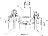
Figure 10 illustrates an enlarged sectional view of the portion of the fluid filter device shown inFigure 9 ; -
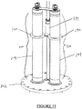
Figure 11 illustrates a perspective view of the top portion of the fluid filter device shown inFigure 9 with the cleaning system being actuated; -
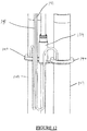
Figure 12 illustrates a rear portion of the fluid filter device illustrated inFigures 9-11 ; -
Figure 13 illustrates a cross-sectional view of the cleaning ring used in the fluid filter device illustrated inFigures 9-12 ; and -
Figure 14 illustrates a schematic view of operation of the cleaning ring used in the fluid filter device illustrated inFigures 9-13 . - With reference to
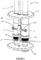
Figure 1 , there is illustrated afluid filter system 10 comprising ahousing 15 having aninlet 20 and anoutlet 25. Disposed withinhousing 15 are a pair of identicalfluid filter devices 100 which will be described in more detail hereinbelow. - In use, a fluid to be filtered such (e.g., water) is fed into
inlet 20 in the direction of arrows A. Thus, the fluid passes through a coarseporous section 105 of eachfluid filter device 100 during which the fluid is subjected to coarse filtration. - Next, the fluid travels within each
fluid filter device 100 in the direction of hashed arrows B. As shown, fluid travels from coarseporous section 105 of eachfluid filter device 100 to a fineporous section 110 of eachfluid filter device 100. Since the fluid is under pressure, it emanates from the fineporous section 110 of eachfluid filter device 100 in the direction of arrows C. The fluid then emanates fromfluid outlet 25. - Thus, fluid that is treated by
fluid filter system 10 is subjected to an initial filtering action by coarseporous section 105 of eachfluid filter device 100. This serves to remove the larger particles from the fluid. As will be apparent to those of skill in the art, those larger particles (possibly together with other fouling materials) may aggregate on the exterior surface of coarseporous section 105 of eachfluid filter device 100. - The fluid is then subjected to a second filtering step whereby finer particles still contained in the fluid are filtered by fine
porous section 110 of eachfluid filter device 100. These fine particles may aggregate (possibly together with other fouling marerials) on a interior surface of fine porous 110 of eachfluid filter device 100. - As will be described in more detail hereinbelow, an aspect of the present invention relates to a cleaning device for removing one or both of coarse particles (possibly together with other fouling marerials) that aggregate on the exterior of coarse
porous section 105 of eachfluid filter device 100 and fine particles (possibly together with other fouling marerials) which aggregate on the interior surface of fineporous section 110 of eachfluid filter device 100. - In
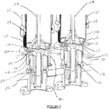
Figures 2-14 , further details are provided onfluid filter device 100. It will be apparent to those of skill in the art thathousing 15 has been removed for clarity purposes only. - Thus, with reference to
Figures 2 and3 , there is shown the lower portion of eachfluid filter device 100 in a so-called "in use" position. As shown, eachfluid filter device 100 is affixed to anisolation flange 101 and a lower flanged 102. - Coarse
porous section 105 of eachfluid filter device 100 comprises anaxial filter screen 107 that is preferably in the form of a wedge wire filter. Preferably, the axial filter screen has the specifications described above for the first porous section of the present fluid filter device. - Disposed above coarse
porous section 105 offluid filter device 100 is acleaning sleeve 115 that is connected to alinear drive 120 by ayolk 125. Disposed below coarseporous section 105 offluid filter device 100 is a T-valve 130. The operation of T-valve will be described herein below. - With particular reference to
Figure 3 , it will be seen that the interior of coarseporous section 105 of eachfluid filter device 100 comprises atie rod 108. The lower portion of coarseporous section 105 offluid filter device 100 comprises an annular backwash opening 111 defined by anannular end portion 112. The distal edges ofannular end portion 112 are in sealing abutment with afilter seal 113 disposed on the upper surface of T-valve 130. - T-
valve 130 comprises a slidingportion 132 that is movable with respect to abase portion 134. T-valve element 130 is normally maintained in the position shown inFigures 2 and3 by a biasing element 136 (e.g., an elastomer spring, a metallic spring, etc.). - As shown particularly in
Figure 3 , cleaningsleeve 115 comprises ascraper element 117 for removing fouling materials from the exterior surface ofaxial filter screen 107 of coarseporous section 105. Preferably,scraper element 117 is in the form of a polymer (e.g., elastomer) scraper. - As described above, in normal use, fluid to be filtered will pass through
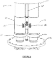
axial filter screen 107 of coarseporous section 105. After a period of time it is possible that particulate or other fouling materials will aggregate on the exterior surface ofaxial filter screen 107 of coarseporous section 105. When it is desired to remove these fouling materials,linear drive 120 is actuated to move cleaningsleeve 115 toward T-valve 130 - seeFigures 4 and5 which show cleaningsleeve 115 being lowered toward T-valve 130. -
Figures 6-8 illustratefluid filter devices 100 wherein cleaningsleeves 115 of eachfluid filter device 100 fully covers coarseporous section 105 while concurrently actuating T-valve to allow backwashing of fluid from the interior offluid filter device 100. - Thus, as shown with particular reference to
Figures 7 and8 , the distal most edge of cleaningsleeve 115 contacts the upper surface of T-valve 130 thereby pushing downward slidingportion 132 and compressing biasingelement 136. The combination of these actions serves to separateannular end portion 112 of cleaningsleeve 115 fromfilter seal 113 of T-valve 130. This serves to allow fluid contained influid filter device 100 to pass through annular backwash opening 111 and out of T-valve 130 in the direction of arrow D. - After the backwashing step has been completed,
linear drive 120 is reversed and cleaningsleeve 115 is retracted away from T-valve 130.Biasing element 136 then moves slidingportion 132 upward such thatannular end portion 112 of cleaningsleeve 115 is returned to a sealing engagement position withfilter seal 113 of T-valve 130. This also exposesaxial filter screen 107 of coarseporous section 105 to allow fluid to be filtered. - With reference to
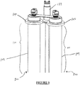
Figures 9-12 , there is illustrated a portion of theporous section 110 offluid filter device 100. - Fine
coarse section 110 comprises anaxial filter screen 109. Preferably,axial filter screen 109 has these specifications described above for the second porous section of the present fluid filter device. - An
annular cleaning ring 140 is disposed on the outside ofaxial filter screen 109.Cleaning ring 140 is attached to adrive yolk 139 which serves to move cleaningring 140 along the exterior of axial filter screen 109 - see, for example,Figure 11 which illustrates cleaning rings 140 being moved along the exterior surface ofaxial filter screen 109. - With particular reference to
Figure 12 , it can been seen that aline 141 is connected to eachannular cleaning ring 140.Line 141 supplies pressurized fluid (liquid or gas) to annular cleaning rings 140. - With particular reference to
Figures 13 and14 , it can been seen thatannular cleaning ring 140 operates in a manner similar to a so-called "water knife". Thus,annular cleaning ring 140 comprises an interior chamber having afluid distribution channel 142, afluid flow transition 143 and aslit 144. - With particular reference to
Figure 14 , and as discussed above with reference toFigure 1 , it is common to have particulate and other foulingmaterials 145 aggregate on the interior surface ofaxial filter screen 109. Foulingmaterials 145 may be removed in the following manner. - A source of pressurized fluid (liquid or gas), preferably water, is fed through
line 141 intoflow distribution channel 142 ofannular cleaning ring 140. The pressurized fluid moves in the direction of arrow E and exits slit 144 as shown to impinge onaxial filter screen 109 at a relatively high pressure. This high pressure fluidblasts fouling material 145 as shown in circle F. Asdrive yolk 139 is actuated to moveannular cleaning ring 140 in the direction of arrow G, foulingmaterials 145 are continuously removed from the interior surface ofaxial filter screen 109. - In a preferred embodiment cleaning rings 140 are actuated at the same time as cleaning
sleeves 115 with the result that backwash of fluid from the interior offluid filter device 100 removes foulingmaterials 145 that have been dislodged from the interior surface ofaxial filter screen 109 by operation of cleaning rings 140. Alternatively, it is possible to actuate cleaningrings 140 whenfluid filter device 100 is not in use - e.g., as part of a periodic maintenance procedure. - While this invention has been described with reference to illustrative embodiments and examples, the description is not intended to be construed in a limiting sense. Thus, various modifications of the illustrative embodiments, as well as other embodiments of the invention, will be apparent to persons skilled in the art upon reference to this description. For example, while the illustrated axial filter screen for use in the present fluid filter device is a so-called wedge wire filter it is possible to use other filters for the axial filter screen - e.g., mesh, screens, sintered elements (e.g., made from brass, stainless steel and the like) and the like. Further, while the illustrated
annular cleaning ring 140 comprises a continuous single,annular slit 144, it is possible to utilize a multiplicity of individual jets or nozzles. Still further, while the illustrated embodiment comprises asingle line 141 connected to a singleannular cleaning ring 140, it is possible to have oneline 141 connected to a multiplicity of annular cleaning rings 140 (e.g., serial connection). It is therefore contemplated that the appended claims will cover any such modifications or embodiments.
Claims (13)
- A fluid filter device (100) comprising:a primary filter section having a first porous section (105) comprising a vertical cylindrical axial filter screen (107); said first porous section having an exterior surface an interior surface anda secondary filter section having second porous section (110) comprising a vertical cylindrical axial filter screen (109); said second porous section having an exterior surface and an interior surface;wherein: (i) the primary filter section and the secondary filter section are in fluid communication with one another, and (ii) the first porous section (105) has a greater porosity than the second porous section (110), the first porous section being the coarse porous section and the second porous section being the fine porous section, so that the fluid that is treated is subjected to:characterized in that said fluid filter device comprises further:- an initial filtering action by said coarse porous section, the larger particles aggregating on said exterior surface of said coarse porous section and then to- a second filtering action by said fine porous section, the fine particles aggregating on said interior surface of said fine porous section,a fluid backwash valve element (130) located at the lower end of the coarse porous section (105) to remove said aggregated larger particles, and operable between: (i) a closed position in which fluid flow is in a direction from the coarse porous section (105) to the fine porous section during normal filtering operation, and (ii) an open position wherein at least a portion of the fluid flow is in a direction from the secondary fine porous section (110) to the primary coarse porous section (105) during backwashing;an annular cleaning ring (140) disposed on the outside of said second porous section and capable of moving axially along said exterior surface of said second porous section to remove said aggregated fine particles (145) therefrom with the help of pressurized fluid supplied to said annular cleaning ring (140).
- The fluid filter device (100) defined in any of claims 1, wherein the first porous section comprises a plurality of first openings.
- The fluid filter device defined (100) in claim 2, wherein each of the first openings comprises a dimension in the range of from about 30 µm to about 500 µm.
- The fluid filter device (100) defined in one of claims 2 or 3, wherein the first porous section (105) is in the form of a first wedge wire filter element.
- The fluid filter device (100) defined in claim 4, wherein the first wedge wire filter element comprises a plurality of first wire elements arranged to define an elongate opening between each adjacent pair of first wire elements.
- The fluid filter device (100) defined in claim 5, wherein each first wire element comprises a tapered portion oriented to have a decreasing cross-sectional dimension in a direction towards an interior of the first wedge wire filter element.
- The fluid filter device (100) defined in any of claims 1 - 6, wherein the second porous section comprises a plurality of second openings.
- The fluid filter device (100) defined in claim 7, wherein each of the second openings comprises a dimension in the range of from about 10 µm to about 150 µm.
- The fluid filter device (100) defined of claim 7 or 8, wherein the second porous section (110) is in the form of a second wedge wire filter element.
- The fluid filter device (100) defined in claim 9, wherein the second wedge wire filter element comprises a plurality of second wire elements arranged to define an elongate opening between each adjacent pair of second wire elements.
- The fluid filter device (100) defined in claim 10, wherein each second wire element comprises a tapered portion oriented to have an increasing cross-sectional dimension in a direction toward an interior of the second wedge wire filter element.
- The fluid filter device (100) defined in any of claims 1 - 11, comprising a driving yoke (139) which serves to move the annular cleaning ring (140) axially along the exterior surface of the second porous section.
- The fluid filter device (100) defined in any of claims 1 - 12, wherein the backwash valve element (130) comprises a biasing element configured to maintain the backwash valve element (130) in the closed position during normal operation of the fluid filter device.
Applications Claiming Priority (2)
| Application Number | Priority Date | Filing Date | Title |
|---|---|---|---|
| US37544810P | 2010-08-20 | 2010-08-20 | |
| PCT/CA2011/000928 WO2012021971A1 (en) | 2010-08-20 | 2011-08-19 | Fluid filter device |
Publications (3)
| Publication Number | Publication Date |
|---|---|
| EP2605848A1 EP2605848A1 (en) | 2013-06-26 |
| EP2605848A4 EP2605848A4 (en) | 2014-01-22 |
| EP2605848B1 true EP2605848B1 (en) | 2019-01-23 |
Family
ID=45604649
Family Applications (1)
| Application Number | Title | Priority Date | Filing Date |
|---|---|---|---|
| EP11817604.9A Expired - Fee Related EP2605848B1 (en) | 2010-08-20 | 2011-08-19 | Fluid filter device |
Country Status (8)
| Country | Link |
|---|---|
| US (1) | US9561455B2 (en) |
| EP (1) | EP2605848B1 (en) |
| JP (1) | JP2013538122A (en) |
| KR (1) | KR20140030092A (en) |
| CN (1) | CN103167898A (en) |
| CA (1) | CA2808323A1 (en) |
| SG (2) | SG187752A1 (en) |
| WO (1) | WO2012021971A1 (en) |
Families Citing this family (16)
| Publication number | Priority date | Publication date | Assignee | Title |
|---|---|---|---|---|
| CN102712018B (en) * | 2009-11-12 | 2015-10-07 | 过滤器安全有限公司 | Filter proximity nozzle |
| KR101454103B1 (en) | 2013-01-24 | 2014-10-23 | 현대중공업 주식회사 | Filter for ballast water |
| EP2784298A1 (en) * | 2013-03-25 | 2014-10-01 | Ingo Platthoff | Oil or fuel filter system |
| CN103808530B (en) * | 2014-01-08 | 2017-01-18 | 青岛双瑞海洋环境工程股份有限公司 | Ship ballast water sampling device for keeping bioactivity |
| IL251485A0 (en) * | 2017-03-30 | 2017-05-29 | אוליאל ערן | Water filter |
| CN109794114B (en) * | 2017-11-16 | 2021-09-17 | 崇鸣投资有限公司 | Unsupported filter comprising a plurality of built-in filter tubes and filter assembly comprising such a filter |
| CN107875708A (en) * | 2017-12-19 | 2018-04-06 | 邱学尧 | Filter pipe and its filter |
| US11679348B2 (en) * | 2017-12-29 | 2023-06-20 | Enercorp Engineered Solutions Inc. | Horizontal sand separator assembly |
| CN109157884A (en) * | 2018-10-24 | 2019-01-08 | 广东石油化工学院 | A kind of Electroplate liquid filter, purging method and system |
| CN110538539B (en) * | 2019-09-24 | 2021-03-23 | 赵佳栋 | Dust and smoke explosion-proof purification device and system for livestock feed processing |
| CN111249790B (en) * | 2020-02-28 | 2021-05-07 | 北京科技大学 | Air-water shared filtering device for underground dry fog dust suppression equipment |
| CN111888825A (en) * | 2020-08-20 | 2020-11-06 | 江苏新天鸿集团有限公司 | Particle impurity removing device |
| US11896989B2 (en) * | 2020-08-26 | 2024-02-13 | Deere & Company | Work vehicle sprayer system and method with self-cleaning filter apparatus |
| US11612837B2 (en) | 2020-09-18 | 2023-03-28 | Pall Corporation | Filter with interconnected hollow elements and method of use |
| US20220088541A1 (en) * | 2020-09-18 | 2022-03-24 | Pall Corporation | Filter with interconnected hollow elements and method of use |
| CN113813674B (en) * | 2021-09-28 | 2023-03-24 | 浙江东原科技股份有限公司 | Filter capable of balancing pressure difference inside and outside filter element |
Family Cites Families (25)
| Publication number | Priority date | Publication date | Assignee | Title |
|---|---|---|---|---|
| US1340599A (en) * | 1919-07-26 | 1920-05-18 | Bird Machine Co | Strainer |
| US4552655A (en) * | 1981-10-06 | 1985-11-12 | Moshe Granot | Self-cleaning filter apparatus |
| JPS6067119U (en) | 1983-10-14 | 1985-05-13 | 日進化成株式会社 | filtration device |
| JPH0730097Y2 (en) | 1991-04-16 | 1995-07-12 | 株式会社八千代環境エンジニアリング | Backwashable double filtration device |
| US5443726A (en) * | 1993-10-13 | 1995-08-22 | Tm Industrial Supply, Inc. | Self-cleaning filter assembly |
| US5527462A (en) | 1994-11-15 | 1996-06-18 | Delaware Capital Formation, Inc. | Filter with axially movable wiper |
| FR2727323A1 (en) | 1994-11-24 | 1996-05-31 | Kim Young Tae | MULTIPLE SCREW PRESS FOR SPINNING OF RESIDUAL MATERIALS |
| US5569383A (en) | 1994-12-15 | 1996-10-29 | Delaware Capital Formation, Inc. | Filter with axially and rotatably movable wiper |
| DE19501896A1 (en) | 1995-01-23 | 1996-07-25 | Knecht Filterwerke Gmbh | Edge filter for liquids |
| US5871652A (en) * | 1995-08-04 | 1999-02-16 | Pipetronics, Inc. | Method for high volume pipeline water filtration |
| JP2000117013A (en) | 1998-10-14 | 2000-04-25 | Marusei Heavy Industry Works Ltd | Superfine type filter for filtering seawater or the like |
| DE10001259A1 (en) | 2000-01-14 | 2001-07-19 | Hydac Filtertechnik Gmbh | Filter includes two elements in casing, to retain particles of differing sizes and has passage connecting filter chambers |
| JP2002011309A (en) | 2000-06-30 | 2002-01-15 | Herushii Techno Chem:Kk | Multilayer filtration type filter |
| US6447680B1 (en) | 2001-04-24 | 2002-09-10 | James Richard | Double pass septic tank outlet filter |
| US20040055946A1 (en) | 2002-09-20 | 2004-03-25 | Sid Harvey Industries, Inc. | Dual filtration system |
| JP4206251B2 (en) | 2002-10-23 | 2009-01-07 | 三菱化工機株式会社 | Filtration apparatus and filtration method using the same |
| JP4051260B2 (en) | 2002-10-25 | 2008-02-20 | Ajバーステック株式会社 | Filtration device |
| US7055699B2 (en) * | 2004-09-01 | 2006-06-06 | Amiad Japan Inc. | Self-cleaning mechanical filter |
| JP2006239530A (en) | 2005-03-02 | 2006-09-14 | Japan Organo Co Ltd | Manufacturing method and manufacturing apparatus of ballast water for ship |
| ATE515303T1 (en) * | 2005-11-14 | 2011-07-15 | Odis Irrigation Equipment Ltd | FILTER CLEANING METHOD AND FILTRATION SYSTEM WITH CLEANING DEVICES |
| WO2008080068A2 (en) | 2006-12-22 | 2008-07-03 | Donaldson Company, Inc. | Gas/liquid separator assembly with preseparator and liquid filter, and methods |
| WO2008115789A1 (en) | 2007-03-19 | 2008-09-25 | Pall Corporation | Fluid treatment arrangements with sets of fluid treatment elements and methods for making and using them |
| JP2010119999A (en) | 2008-11-21 | 2010-06-03 | Sumitomo Electric Ind Ltd | Apparatus for treating water |
| CN201353455Y (en) | 2009-03-18 | 2009-12-02 | 丹东东方机电工程有限公司 | Millimetre-grade/micron-grade multifunctional automatic-cleaning filter |
| CN101785941A (en) | 2010-03-23 | 2010-07-28 | 沈阳万通健康用品制造有限公司 | Water filter |
-
2011
- 2011-08-19 WO PCT/CA2011/000928 patent/WO2012021971A1/en active Application Filing
- 2011-08-19 US US13/817,915 patent/US9561455B2/en not_active Expired - Fee Related
- 2011-08-19 CN CN201180050654XA patent/CN103167898A/en active Pending
- 2011-08-19 SG SG2013009295A patent/SG187752A1/en unknown
- 2011-08-19 SG SG10201506600QA patent/SG10201506600QA/en unknown
- 2011-08-19 EP EP11817604.9A patent/EP2605848B1/en not_active Expired - Fee Related
- 2011-08-19 CA CA2808323A patent/CA2808323A1/en not_active Abandoned
- 2011-08-19 KR KR1020137007085A patent/KR20140030092A/en not_active Application Discontinuation
- 2011-08-19 JP JP2013525091A patent/JP2013538122A/en active Pending
Non-Patent Citations (1)
| Title |
|---|
| None * |
Also Published As
| Publication number | Publication date |
|---|---|
| KR20140030092A (en) | 2014-03-11 |
| JP2013538122A (en) | 2013-10-10 |
| SG187752A1 (en) | 2013-03-28 |
| EP2605848A1 (en) | 2013-06-26 |
| EP2605848A4 (en) | 2014-01-22 |
| WO2012021971A1 (en) | 2012-02-23 |
| SG10201506600QA (en) | 2015-09-29 |
| US20130206674A1 (en) | 2013-08-15 |
| US9561455B2 (en) | 2017-02-07 |
| CA2808323A1 (en) | 2012-02-23 |
| CN103167898A (en) | 2013-06-19 |
Similar Documents
| Publication | Publication Date | Title |
|---|---|---|
| EP2605848B1 (en) | Fluid filter device | |
| EP2637761B1 (en) | Ship ballast water treatment system | |
| US8852441B2 (en) | Apparatus for purifying liquids, in particular for purifying ballast water | |
| KR101130521B1 (en) | Apparatus and method for separating and filtering particles and organisms from a high volume flowing liquid | |
| KR100968403B1 (en) | Apparatus and method for separating and filtering particles and organisms from flowing liquid | |
| US9115009B2 (en) | Fluid treatment system | |
| US20110108483A1 (en) | Filter unit with filter bank | |
| EP2805064B1 (en) | Fluid flow modifier and fluid treatment system incorporating same | |
| EP2498891B1 (en) | A method and a plant for the treatment of water and wastewater | |
| KR101954760B1 (en) | Water Cleaning System Having Backflushing Filter and Water Cleaning Method thereof | |
| KR101709537B1 (en) | Water treatment apparatus for sea water/freshwater | |
| CN214829654U (en) | Marine ballast water treatment facilities | |
| CN214299698U (en) | Marine ballast water treatment facilities | |
| CN113149300A (en) | Marine ballast water treatment facilities | |
| KR20210002418U (en) | Spring filter for easy water flow | |
| SE0602619L (en) | Method and system for filter treatment | |
| KR20040045103A (en) | Apparatus for generating whirlpool of filter for clean water |
Legal Events
| Date | Code | Title | Description |
|---|---|---|---|
| PUAI | Public reference made under article 153(3) epc to a published international application that has entered the european phase |
Free format text: ORIGINAL CODE: 0009012 |
|
| 17P | Request for examination filed |
Effective date: 20130228 |
|
| AK | Designated contracting states |
Kind code of ref document: A1 Designated state(s): AL AT BE BG CH CY CZ DE DK EE ES FI FR GB GR HR HU IE IS IT LI LT LU LV MC MK MT NL NO PL PT RO RS SE SI SK SM TR |
|
| DAX | Request for extension of the european patent (deleted) | ||
| A4 | Supplementary search report drawn up and despatched |
Effective date: 20131219 |
|
| RIC1 | Information provided on ipc code assigned before grant |
Ipc: B01D 29/50 20060101AFI20131213BHEP Ipc: B01D 29/64 20060101ALI20131213BHEP |
|
| 17Q | First examination report despatched |
Effective date: 20160630 |
|
| STAA | Information on the status of an ep patent application or granted ep patent |
Free format text: STATUS: EXAMINATION IS IN PROGRESS |
|
| GRAP | Despatch of communication of intention to grant a patent |
Free format text: ORIGINAL CODE: EPIDOSNIGR1 |
|
| STAA | Information on the status of an ep patent application or granted ep patent |
Free format text: STATUS: GRANT OF PATENT IS INTENDED |
|
| INTG | Intention to grant announced |
Effective date: 20180523 |
|
| GRAS | Grant fee paid |
Free format text: ORIGINAL CODE: EPIDOSNIGR3 |
|
| GRAJ | Information related to disapproval of communication of intention to grant by the applicant or resumption of examination proceedings by the epo deleted |
Free format text: ORIGINAL CODE: EPIDOSDIGR1 |
|
| GRAL | Information related to payment of fee for publishing/printing deleted |
Free format text: ORIGINAL CODE: EPIDOSDIGR3 |
|
| STAA | Information on the status of an ep patent application or granted ep patent |
Free format text: STATUS: EXAMINATION IS IN PROGRESS |
|
| INTC | Intention to grant announced (deleted) | ||
| GRAR | Information related to intention to grant a patent recorded |
Free format text: ORIGINAL CODE: EPIDOSNIGR71 |
|
| STAA | Information on the status of an ep patent application or granted ep patent |
Free format text: STATUS: GRANT OF PATENT IS INTENDED |
|
| INTG | Intention to grant announced |
Effective date: 20181112 |
|
| GRAA | (expected) grant |
Free format text: ORIGINAL CODE: 0009210 |
|
| STAA | Information on the status of an ep patent application or granted ep patent |
Free format text: STATUS: THE PATENT HAS BEEN GRANTED |
|
| AK | Designated contracting states |
Kind code of ref document: B1 Designated state(s): AL AT BE BG CH CY CZ DE DK EE ES FI FR GB GR HR HU IE IS IT LI LT LU LV MC MK MT NL NO PL PT RO RS SE SI SK SM TR |
|
| REG | Reference to a national code |
Ref country code: GB Ref legal event code: FG4D |
|
| REG | Reference to a national code |
Ref country code: CH Ref legal event code: EP |
|
| REG | Reference to a national code |
Ref country code: AT Ref legal event code: REF Ref document number: 1090984 Country of ref document: AT Kind code of ref document: T Effective date: 20190215 |
|
| REG | Reference to a national code |
Ref country code: IE Ref legal event code: FG4D |
|
| REG | Reference to a national code |
Ref country code: DE Ref legal event code: R096 Ref document number: 602011055967 Country of ref document: DE |
|
| REG | Reference to a national code |
Ref country code: NL Ref legal event code: MP Effective date: 20190123 |
|
| PG25 | Lapsed in a contracting state [announced via postgrant information from national office to epo] |
Ref country code: NL Free format text: LAPSE BECAUSE OF FAILURE TO SUBMIT A TRANSLATION OF THE DESCRIPTION OR TO PAY THE FEE WITHIN THE PRESCRIBED TIME-LIMIT Effective date: 20190123 |
|
| PG25 | Lapsed in a contracting state [announced via postgrant information from national office to epo] |
Ref country code: SE Free format text: LAPSE BECAUSE OF FAILURE TO SUBMIT A TRANSLATION OF THE DESCRIPTION OR TO PAY THE FEE WITHIN THE PRESCRIBED TIME-LIMIT Effective date: 20190123 Ref country code: PT Free format text: LAPSE BECAUSE OF FAILURE TO SUBMIT A TRANSLATION OF THE DESCRIPTION OR TO PAY THE FEE WITHIN THE PRESCRIBED TIME-LIMIT Effective date: 20190523 Ref country code: PL Free format text: LAPSE BECAUSE OF FAILURE TO SUBMIT A TRANSLATION OF THE DESCRIPTION OR TO PAY THE FEE WITHIN THE PRESCRIBED TIME-LIMIT Effective date: 20190123 Ref country code: LT Free format text: LAPSE BECAUSE OF FAILURE TO SUBMIT A TRANSLATION OF THE DESCRIPTION OR TO PAY THE FEE WITHIN THE PRESCRIBED TIME-LIMIT Effective date: 20190123 Ref country code: ES Free format text: LAPSE BECAUSE OF FAILURE TO SUBMIT A TRANSLATION OF THE DESCRIPTION OR TO PAY THE FEE WITHIN THE PRESCRIBED TIME-LIMIT Effective date: 20190123 Ref country code: NO Free format text: LAPSE BECAUSE OF FAILURE TO SUBMIT A TRANSLATION OF THE DESCRIPTION OR TO PAY THE FEE WITHIN THE PRESCRIBED TIME-LIMIT Effective date: 20190423 Ref country code: FI Free format text: LAPSE BECAUSE OF FAILURE TO SUBMIT A TRANSLATION OF THE DESCRIPTION OR TO PAY THE FEE WITHIN THE PRESCRIBED TIME-LIMIT Effective date: 20190123 |
|
| REG | Reference to a national code |
Ref country code: AT Ref legal event code: MK05 Ref document number: 1090984 Country of ref document: AT Kind code of ref document: T Effective date: 20190123 |
|
| PG25 | Lapsed in a contracting state [announced via postgrant information from national office to epo] |
Ref country code: IS Free format text: LAPSE BECAUSE OF FAILURE TO SUBMIT A TRANSLATION OF THE DESCRIPTION OR TO PAY THE FEE WITHIN THE PRESCRIBED TIME-LIMIT Effective date: 20190523 Ref country code: BG Free format text: LAPSE BECAUSE OF FAILURE TO SUBMIT A TRANSLATION OF THE DESCRIPTION OR TO PAY THE FEE WITHIN THE PRESCRIBED TIME-LIMIT Effective date: 20190423 Ref country code: RS Free format text: LAPSE BECAUSE OF FAILURE TO SUBMIT A TRANSLATION OF THE DESCRIPTION OR TO PAY THE FEE WITHIN THE PRESCRIBED TIME-LIMIT Effective date: 20190123 Ref country code: HR Free format text: LAPSE BECAUSE OF FAILURE TO SUBMIT A TRANSLATION OF THE DESCRIPTION OR TO PAY THE FEE WITHIN THE PRESCRIBED TIME-LIMIT Effective date: 20190123 Ref country code: LV Free format text: LAPSE BECAUSE OF FAILURE TO SUBMIT A TRANSLATION OF THE DESCRIPTION OR TO PAY THE FEE WITHIN THE PRESCRIBED TIME-LIMIT Effective date: 20190123 Ref country code: GR Free format text: LAPSE BECAUSE OF FAILURE TO SUBMIT A TRANSLATION OF THE DESCRIPTION OR TO PAY THE FEE WITHIN THE PRESCRIBED TIME-LIMIT Effective date: 20190424 |
|
| REG | Reference to a national code |
Ref country code: DE Ref legal event code: R097 Ref document number: 602011055967 Country of ref document: DE |
|
| PG25 | Lapsed in a contracting state [announced via postgrant information from national office to epo] |
Ref country code: CZ Free format text: LAPSE BECAUSE OF FAILURE TO SUBMIT A TRANSLATION OF THE DESCRIPTION OR TO PAY THE FEE WITHIN THE PRESCRIBED TIME-LIMIT Effective date: 20190123 Ref country code: SK Free format text: LAPSE BECAUSE OF FAILURE TO SUBMIT A TRANSLATION OF THE DESCRIPTION OR TO PAY THE FEE WITHIN THE PRESCRIBED TIME-LIMIT Effective date: 20190123 Ref country code: AL Free format text: LAPSE BECAUSE OF FAILURE TO SUBMIT A TRANSLATION OF THE DESCRIPTION OR TO PAY THE FEE WITHIN THE PRESCRIBED TIME-LIMIT Effective date: 20190123 Ref country code: EE Free format text: LAPSE BECAUSE OF FAILURE TO SUBMIT A TRANSLATION OF THE DESCRIPTION OR TO PAY THE FEE WITHIN THE PRESCRIBED TIME-LIMIT Effective date: 20190123 Ref country code: DK Free format text: LAPSE BECAUSE OF FAILURE TO SUBMIT A TRANSLATION OF THE DESCRIPTION OR TO PAY THE FEE WITHIN THE PRESCRIBED TIME-LIMIT Effective date: 20190123 Ref country code: RO Free format text: LAPSE BECAUSE OF FAILURE TO SUBMIT A TRANSLATION OF THE DESCRIPTION OR TO PAY THE FEE WITHIN THE PRESCRIBED TIME-LIMIT Effective date: 20190123 Ref country code: IT Free format text: LAPSE BECAUSE OF FAILURE TO SUBMIT A TRANSLATION OF THE DESCRIPTION OR TO PAY THE FEE WITHIN THE PRESCRIBED TIME-LIMIT Effective date: 20190123 |
|
| PG25 | Lapsed in a contracting state [announced via postgrant information from national office to epo] |
Ref country code: SM Free format text: LAPSE BECAUSE OF FAILURE TO SUBMIT A TRANSLATION OF THE DESCRIPTION OR TO PAY THE FEE WITHIN THE PRESCRIBED TIME-LIMIT Effective date: 20190123 |
|
| PLBE | No opposition filed within time limit |
Free format text: ORIGINAL CODE: 0009261 |
|
| STAA | Information on the status of an ep patent application or granted ep patent |
Free format text: STATUS: NO OPPOSITION FILED WITHIN TIME LIMIT |
|
| PG25 | Lapsed in a contracting state [announced via postgrant information from national office to epo] |
Ref country code: AT Free format text: LAPSE BECAUSE OF FAILURE TO SUBMIT A TRANSLATION OF THE DESCRIPTION OR TO PAY THE FEE WITHIN THE PRESCRIBED TIME-LIMIT Effective date: 20190123 |
|
| 26N | No opposition filed |
Effective date: 20191024 |
|
| PG25 | Lapsed in a contracting state [announced via postgrant information from national office to epo] |
Ref country code: SI Free format text: LAPSE BECAUSE OF FAILURE TO SUBMIT A TRANSLATION OF THE DESCRIPTION OR TO PAY THE FEE WITHIN THE PRESCRIBED TIME-LIMIT Effective date: 20190123 |
|
| REG | Reference to a national code |
Ref country code: DE Ref legal event code: R119 Ref document number: 602011055967 Country of ref document: DE |
|
| PG25 | Lapsed in a contracting state [announced via postgrant information from national office to epo] |
Ref country code: TR Free format text: LAPSE BECAUSE OF FAILURE TO SUBMIT A TRANSLATION OF THE DESCRIPTION OR TO PAY THE FEE WITHIN THE PRESCRIBED TIME-LIMIT Effective date: 20190123 |
|
| GBPC | Gb: european patent ceased through non-payment of renewal fee |
Effective date: 20190819 |
|
| PG25 | Lapsed in a contracting state [announced via postgrant information from national office to epo] |
Ref country code: LU Free format text: LAPSE BECAUSE OF NON-PAYMENT OF DUE FEES Effective date: 20190819 Ref country code: CH Free format text: LAPSE BECAUSE OF NON-PAYMENT OF DUE FEES Effective date: 20190831 Ref country code: LI Free format text: LAPSE BECAUSE OF NON-PAYMENT OF DUE FEES Effective date: 20190831 Ref country code: MC Free format text: LAPSE BECAUSE OF FAILURE TO SUBMIT A TRANSLATION OF THE DESCRIPTION OR TO PAY THE FEE WITHIN THE PRESCRIBED TIME-LIMIT Effective date: 20190123 |
|
| REG | Reference to a national code |
Ref country code: BE Ref legal event code: MM Effective date: 20190831 |
|
| PG25 | Lapsed in a contracting state [announced via postgrant information from national office to epo] |
Ref country code: FR Free format text: LAPSE BECAUSE OF NON-PAYMENT OF DUE FEES Effective date: 20190831 Ref country code: IE Free format text: LAPSE BECAUSE OF NON-PAYMENT OF DUE FEES Effective date: 20190819 Ref country code: DE Free format text: LAPSE BECAUSE OF NON-PAYMENT OF DUE FEES Effective date: 20200303 |
|
| PG25 | Lapsed in a contracting state [announced via postgrant information from national office to epo] |
Ref country code: BE Free format text: LAPSE BECAUSE OF NON-PAYMENT OF DUE FEES Effective date: 20190831 Ref country code: GB Free format text: LAPSE BECAUSE OF NON-PAYMENT OF DUE FEES Effective date: 20190819 |
|
| PG25 | Lapsed in a contracting state [announced via postgrant information from national office to epo] |
Ref country code: CY Free format text: LAPSE BECAUSE OF FAILURE TO SUBMIT A TRANSLATION OF THE DESCRIPTION OR TO PAY THE FEE WITHIN THE PRESCRIBED TIME-LIMIT Effective date: 20190123 |
|
| PG25 | Lapsed in a contracting state [announced via postgrant information from national office to epo] |
Ref country code: MT Free format text: LAPSE BECAUSE OF FAILURE TO SUBMIT A TRANSLATION OF THE DESCRIPTION OR TO PAY THE FEE WITHIN THE PRESCRIBED TIME-LIMIT Effective date: 20190123 Ref country code: HU Free format text: LAPSE BECAUSE OF FAILURE TO SUBMIT A TRANSLATION OF THE DESCRIPTION OR TO PAY THE FEE WITHIN THE PRESCRIBED TIME-LIMIT; INVALID AB INITIO Effective date: 20110819 |
|
| PG25 | Lapsed in a contracting state [announced via postgrant information from national office to epo] |
Ref country code: MK Free format text: LAPSE BECAUSE OF FAILURE TO SUBMIT A TRANSLATION OF THE DESCRIPTION OR TO PAY THE FEE WITHIN THE PRESCRIBED TIME-LIMIT Effective date: 20190123 |