EP2605634B1 - Harvester discharge spout - Google Patents
Harvester discharge spout Download PDFInfo
- Publication number
- EP2605634B1 EP2605634B1 EP11733860.8A EP11733860A EP2605634B1 EP 2605634 B1 EP2605634 B1 EP 2605634B1 EP 11733860 A EP11733860 A EP 11733860A EP 2605634 B1 EP2605634 B1 EP 2605634B1
- Authority
- EP
- European Patent Office
- Prior art keywords
- support frame
- control flap
- discharge spout
- outer end
- crop
- Prior art date
- Legal status (The legal status is an assumption and is not a legal conclusion. Google has not performed a legal analysis and makes no representation as to the accuracy of the status listed.)
- Not-in-force
Links
- 241001124569 Lycaenidae Species 0.000 description 4
- 210000005069 ears Anatomy 0.000 description 4
- 239000004459 forage Substances 0.000 description 4
- 238000003306 harvesting Methods 0.000 description 1
Images

Classifications
-
- A—HUMAN NECESSITIES
- A01—AGRICULTURE; FORESTRY; ANIMAL HUSBANDRY; HUNTING; TRAPPING; FISHING
- A01D—HARVESTING; MOWING
- A01D43/00—Mowers combined with apparatus performing additional operations while mowing
- A01D43/08—Mowers combined with apparatus performing additional operations while mowing with means for cutting up the mown crop, e.g. forage harvesters
- A01D43/086—Mowers combined with apparatus performing additional operations while mowing with means for cutting up the mown crop, e.g. forage harvesters and means for collecting, gathering or loading mown material
- A01D43/087—Mowers combined with apparatus performing additional operations while mowing with means for cutting up the mown crop, e.g. forage harvesters and means for collecting, gathering or loading mown material with controllable discharge spout
Definitions
- the invention relates to forage harvesters/or combine harvesters and in particular to control flap arrangements used at the end of discharge spouts of such machines to control the discharge of harvested crop into an accompanying trailer.
- One known arrangement provides a harvester discharge spout outlet control flap arrangement comprising a first support frame for attachment to an outer end of a harvester discharge spout for supporting first crop deflecting control flap means, a second support frame for supporting second crop deflecting control flap means, and actuating means for pivoting the second support frame relative to the first support frame to deflect crop discharge from the outer end of the discharge spout.
- control flap arrangements must be easily changeable to adapt the crop discharge flow path according the crop harvested. This also requires easy replacement.
- a harvester discharge spout outlet control flap arrangement is characterised in that the first and second crop deflecting control flap means are detachably supported by first and second support frames, respectively, and in that the second support frame is pivotally mounted on an outer end of the first support frame.
- the actuator acts directly between the first and second support frames.
- Such an arrangement enables the crop defecting control flap means carried by the first or second support frame to be easily replaced when worn or damaged by impact from the crop etc. by simply detaching the control flap means from the relevant support need to disconnect frame without the any other items.
- a second crop deflecting control flap means of a shorter length can be easily replaced with a longer one to adjust the crop discharge flow path.
- the first support frame may also be pivotally mounted on the outer end of the discharge spout and a linkage may connect the second support frame with the end of the discharge spout so that movement of the second support frame relative to the first support frame by the actuator also moves the first support frame relative to the outer end of the discharge spout.
- a third support frame may also be pivotally mounted on the outer end of the second support frame for detachably supporting a third crop deflecting control flap means therefrom and a further linkage connects the third support frame with the first support frame so that movement of the second support frame relative to the first support frame by the actuator also moves the third support frame relative to the first support frame.
- the actuator is preferably a hydraulic cylinder.
- a sensor is provided to give a signal indicative of the relative angle between he support frames or between one of the support frames and the outer end of the discharge spout to enable the operation of the actuator to be controlled to give a desired crop discharge flow path.
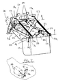
- a forage harvester discharge spout 10 is rotatable as indicated by the arrow R about a substantially vertical axis X by hydraulic motor (not shown).
- the discharge spout 10 can also be raised and lowered as indicated by the arrow S by being pivoted by a hydraulic ram 11 about an axis Y which is as at right angles to axis X.
- the outer end 12 of discharge spout 11 is provided with a control flap arrangement 13 which has a first control flap 14 and a second control flap 15 which can be pivoted relative to each other in order to change the flow path of the crop being discharged from the end of the spout 10.
- the first control flap 14 is supported on a first support frame 16 which is pivoted on a mounting member 17 which is bolted to the end of the discharge spout 10.
- the first support number 16 is free to pivot relative to the support member 17 about an axis A - A (see figure 2 ) via pins 18 which extend through downwardly extending ears 19 provided on the first support frame.
- a second support frame 20 which can pivot relative to the fist support frame 16 about an axis B - B via pins 21 which extend through a second pair of downwardly extending ears 22 on the first support frame 16.
- First control flap 14 is detachably supported below first support framel6 using nuts and bolts or other detachable fasteners which extend through holes 23 and 24 provided in first frame 16.
- second control flap 15 is supported from second support frame 20 via detachable nuts and bolts or other fasteners extending through holes 25 and 26 provided on the second support frame.
- a double acting hydraulic cylinder 27 extends between a support bracket 28 on first support frame 16 and a second support bracket 29 on second support frame 20.
- Second support frame 20 is also connected with mounting member 17 via links 30 which are pivotally connected at 31 and 32 with the second support frame 20 and the mounting member 17.
- lever arm Z between the pivot axis B-B and the pivotal connection 31 of link 30 with the second support frame 20. This lever arm ensures that, when the actuator 27 is operated to pivot the second support frame 20 and the second control flap 15 relative to the first support frame 16 and the fist control flap 14, the first support member 16 and associated control flap 14 are also caused to pivot about axis A - A.
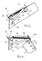
- Figure 3 shows the position adopted by the support frames 16 and 20 and their associated control flaps 14 and 15 when the cylinder 27 is in its fully retracted position. As can be seen this gives a substantially straight configuration of the two control flaps 14 and 15 relative to each other.
- Figure 4 shows the configuration of the control flaps 14 and 15 when the ram 27 is in its fully extended position. This shows the two control flaps in their most relatively pivoted position in which the crop exiting from the spout 10 will be most deflected.
- Tension springs 33 are arranged to act between brackets 20a on second support frame 20 and eyes 17a on support member 17. These tension springs take up all the slackness in the pivots and linkage connections and thus reduce vibration and associated noise etc.
- control flaps 14 and 15 are subject to a high rate of wear due to the impacts of the crop being discharged from spout 10. These flaps thus require relatively frequent replacements and, because the flaps are easily detachable from the associated support frames 16 and 20, these flaps can be easily replaced without the need to disconnect any of the other components of the control flap arrangement.
- control flap 15 can be easily substituted by a control flap which is longer or shorter (in direction of crop flow) to adjust the crop discharge flow path.
- the control flap arrangement may be provided with a sensor 34 (see Figure 2 ) which, for example, has an input arm 35 connected by a link 36 with a pivot pin 37 mounted one of the holes 24 in one of the downwardly projecting ears 19.
- This sensor 34 provides an indication of the pivot angle of the first support frame 16 (and hence the first control flap 14) relative to the mounting member 17. This pivot angle is also indicative of the pivoting of control flap 15 relative to control flap 14 due to the presence of the control links 30.
- the signal from sensor 34 can therefore be used as an input into a control system for adjusting the relative angle of control flaps 14 and 15 and thus the discharge path of the crop being discharged from the spout 10.
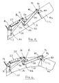
- FIGS 5 and 6 show and extended form of the control flap arrangement shown in figures 2 to 4 in which a third control flap 40 is mounted on a third support frame 41 which is pivotally mounted on a support structure 42 secured to the outer end of the second control flap 15 for pivoting about an axis C - C relative to the second control flap.
- the third support frame 41 is also connected by a link 50 and pins 51 to the third support frame 41 and by pins 52 to extended downwardly projecting ears 22 provided on the first support frame 16.
- Flap 40 is again secured to frame 41 by nuts and bolts or other fasteners extending through holes 43 and other holes (not visible in Figures 5 and 6 ) in the top of frame 41.
- Present invention thus provides is simple but effective control arrangement for the control flaps of a forage harvester discharge spout.
- the invention is also applicable to the discharge spouts of other harvesters such as combine harvesters used to harvest grain or similar crops.
Landscapes
- Life Sciences & Earth Sciences (AREA)
- Environmental Sciences (AREA)
- Harvester Elements (AREA)
Description
- The invention relates to forage harvesters/or combine harvesters and in particular to control flap arrangements used at the end of discharge spouts of such machines to control the discharge of harvested crop into an accompanying trailer.
- One known arrangement, described in
DE 33 16 325 A1 - Such control flap arrangements are well known but suffer from problems due to replacement necessitated by wear caused by continual impact from the harvested crop.
- Furthermore, the geometry of such control flap arrangements must be easily changeable to adapt the crop discharge flow path according the crop harvested. This also requires easy replacement.
- It is therefore an object of the present invention to provide an improved control flap arrangement which addresses the above problem.
- A harvester discharge spout outlet control flap arrangement according to the present invention is characterised in that the first and second crop deflecting control flap means are detachably supported by first and second support frames, respectively, and in that the second support frame is pivotally mounted on an outer end of the first support frame.
- Preferably the actuator acts directly between the first and second support frames.
- Such an arrangement enables the crop defecting control flap means carried by the first or second support frame to be easily replaced when worn or damaged by impact from the crop etc. by simply detaching the control flap means from the relevant support need to disconnect frame without the any other items. In addition a second crop deflecting control flap means of a shorter length can be easily replaced with a longer one to adjust the crop discharge flow path.
- The first support frame may also be pivotally mounted on the outer end of the discharge spout and a linkage may connect the second support frame with the end of the discharge spout so that movement of the second support frame relative to the first support frame by the actuator also moves the first support frame relative to the outer end of the discharge spout.
- A third support frame may also be pivotally mounted on the outer end of the second support frame for detachably supporting a third crop deflecting control flap means therefrom and a further linkage connects the third support frame with the first support frame so that movement of the second support frame relative to the first support frame by the actuator also moves the third support frame relative to the first support frame.
- The actuator is preferably a hydraulic cylinder.
- Also preferably a sensor is provided to give a signal indicative of the relative angle between he support frames or between one of the support frames and the outer end of the discharge spout to enable the operation of the actuator to be controlled to give a desired crop discharge flow path.
- The present invention will now be described, by way of example only, with reference to the accompanying drawings in which:
-
Figure 1 shows a discharge spout for a forage harvester provided with a spout outlet control flap arrangement in accordance with the present invention; -
Figure 2 shows a perspective view of the spout outlet control flap arrangement fitted to the discharge spout offigure 1 ; -
Figure 3 shows a side view of the spout outlet control flap arrangement offigure 2 in the straight configuration; -
Figure 4 shows the control flap Arrangement offigure 2 in the fully angled position -
Figure 5 shows an extended version of the control flap arrangement offigure 2 in the straight position, -
Figure 6 shows the control flap arrangement offigure 5 in the fully angled position. - Referring to the drawings, a forage
harvester discharge spout 10 is rotatable as indicated by the arrow R about a substantially vertical axis X by hydraulic motor (not shown). - The
discharge spout 10 can also be raised and lowered as indicated by the arrow S by being pivoted by a hydraulic ram 11 about an axis Y which is as at right angles to axis X. - The
outer end 12 of discharge spout 11 is provided with acontrol flap arrangement 13 which has afirst control flap 14 and asecond control flap 15 which can be pivoted relative to each other in order to change the flow path of the crop being discharged from the end of thespout 10. - In accordance with the present invention, the
first control flap 14 is supported on afirst support frame 16 which is pivoted on amounting member 17 which is bolted to the end of thedischarge spout 10. Thefirst support number 16 is free to pivot relative to thesupport member 17 about an axis A - A (seefigure 2 ) viapins 18 which extend through downwardly extendingears 19 provided on the first support frame. - Mounted on the outer end of the
first support frame 16 is asecond support frame 20 which can pivot relative to thefist support frame 16 about an axis B - B viapins 21 which extend through a second pair of downwardly extendingears 22 on thefirst support frame 16. -
First control flap 14 is detachably supported below first support framel6 using nuts and bolts or other detachable fasteners which extend throughholes first frame 16. - Similarly,
second control flap 15 is supported fromsecond support frame 20 via detachable nuts and bolts or other fasteners extending throughholes - A double acting
hydraulic cylinder 27 extends between asupport bracket 28 onfirst support frame 16 and asecond support bracket 29 onsecond support frame 20.Second support frame 20 is also connected withmounting member 17 vialinks 30 which are pivotally connected at 31 and 32 with thesecond support frame 20 and themounting member 17. - As best seen from
figure 4 , there is a lever arm Z between the pivot axis B-B and thepivotal connection 31 oflink 30 with thesecond support frame 20. This lever arm ensures that, when theactuator 27 is operated to pivot thesecond support frame 20 and thesecond control flap 15 relative to thefirst support frame 16 and thefist control flap 14, thefirst support member 16 and associatedcontrol flap 14 are also caused to pivot about axis A - A. -
Figure 3 shows the position adopted by thesupport frames control flaps cylinder 27 is in its fully retracted position. As can be seen this gives a substantially straight configuration of the twocontrol flaps -
Figure 4 shows the configuration of thecontrol flaps ram 27 is in its fully extended position. This shows the two control flaps in their most relatively pivoted position in which the crop exiting from thespout 10 will be most deflected. -
Tension springs 33 are arranged to act betweenbrackets 20a onsecond support frame 20 andeyes 17a onsupport member 17. These tension springs take up all the slackness in the pivots and linkage connections and thus reduce vibration and associated noise etc. - As has been indicated earlier, the
control flaps spout 10. These flaps thus require relatively frequent replacements and, because the flaps are easily detachable from the associatedsupport frames - In addition the
control flap 15 can be easily substituted by a control flap which is longer or shorter (in direction of crop flow) to adjust the crop discharge flow path. - The control flap arrangement may be provided with a sensor 34 (see
Figure 2 ) which, for example, has aninput arm 35 connected by alink 36 with apivot pin 37 mounted one of theholes 24 in one of the downwardly projectingears 19. Thissensor 34 provides an indication of the pivot angle of the first support frame 16 (and hence the first control flap 14) relative to themounting member 17. This pivot angle is also indicative of the pivoting ofcontrol flap 15 relative tocontrol flap 14 due to the presence of thecontrol links 30. - The signal from
sensor 34 can therefore be used as an input into a control system for adjusting the relative angle ofcontrol flaps spout 10. -
Figures 5 and 6 show and extended form of the control flap arrangement shown infigures 2 to 4 in which athird control flap 40 is mounted on athird support frame 41 which is pivotally mounted on asupport structure 42 secured to the outer end of thesecond control flap 15 for pivoting about an axis C - C relative to the second control flap. Thethird support frame 41 is also connected by alink 50 andpins 51 to thethird support frame 41 and bypins 52 to extended downwardly projectingears 22 provided on thefirst support frame 16.Flap 40 is again secured to frame 41 by nuts and bolts or other fasteners extending throughholes 43 and other holes (not visible inFigures 5 and 6 ) in the top offrame 41. - Thus in this extended arrangement, when the
cylinder 27 is in its fully retracted position all threecontrol flaps figure 5 and when thecylinder 27 is extended the control flaps assume a progressively more curved relative configuration, as shown infigure 6 . - Again all three
control flaps single cylinder 27. - Present invention thus provides is simple but effective control arrangement for the control flaps of a forage harvester discharge spout.
- As will be appreciated, the invention is also applicable to the discharge spouts of other harvesters such as combine harvesters used to harvest grain or similar crops.
Claims (6)
- A harvester discharge spout outlet control flap arrangement comprising a first support frame (16) for attachment to an outer end of a harvester discharge spout (10) for supporting first crop deflecting control flap means (14), a second support frame (20) for supporting second crop deflecting control flap means (15), and actuating means (27) for pivoting the second support frame (20) relative to the first support frame (16) to deflect crop discharge from the outer end of the discharge spout, characterised in that the first (14) and second (15) crop deflecting control flap means are detachably supported by first (16) and second (20) support frames, respectively, and in that the second support frame (20) is pivotally mounted on an outer end of the first support frame (16).
- A control flap arrangement according to claim 1 in which the actuator (27) acts directly between the first (16) and second (20) support frames.
- A control flap arrangement according to claim 1 or 2 in which the first support frame (16) is pivotally mounted on the outer end of the discharge spout (10) and a linkage (30) connects the second support frame (20) with the end of the discharge spout (10) so that movement of the second support frame (20) relative to the first support frame (16) by the actuator (27) also moves the first support frame (16) relative to the outer end of the discharge spout (10).
- A control flap arrangement according to claim 3 in which a third support frame (41) is pivotally mounted on the outer end of the second support frame (20) for detachably supporting a third crop deflecting control flap means (40) therefrom and a further linkage (50) connects the third support frame (41) with the first support frame (16) so that movement of the second support frame (20) relative to the first support frame (16) by the actuator (27) also moves the third support frame (41) relative to the first support frame (16).
- A control flap arrangement according to any one of claims 1 to 4 in which the actuator (27) is a hydraulic cylinder.
- A control flap arrangement according to any one of claims 1 to 5 in which a sensor (34) is provided to give a signal indicative of the relative angle between the support frames (16, 20) or between one of the support frames and the outer end of the discharge spout (10) to enable the operation of the actuator (27) to be controlled to give a desired crop discharge flow path.
Applications Claiming Priority (2)
| Application Number | Priority Date | Filing Date | Title |
|---|---|---|---|
| GBGB1013942.6A GB201013942D0 (en) | 2010-08-20 | 2010-08-20 | Harvester discharge spout |
| PCT/EP2011/062331 WO2012022564A1 (en) | 2010-08-20 | 2011-07-19 | Harvester discharge spouts |
Publications (2)
| Publication Number | Publication Date |
|---|---|
| EP2605634A1 EP2605634A1 (en) | 2013-06-26 |
| EP2605634B1 true EP2605634B1 (en) | 2015-11-25 |
Family
ID=42984404
Family Applications (1)
| Application Number | Title | Priority Date | Filing Date |
|---|---|---|---|
| EP11733860.8A Not-in-force EP2605634B1 (en) | 2010-08-20 | 2011-07-19 | Harvester discharge spout |
Country Status (3)
| Country | Link |
|---|---|
| EP (1) | EP2605634B1 (en) |
| GB (1) | GB201013942D0 (en) |
| WO (1) | WO2012022564A1 (en) |
Cited By (1)
| Publication number | Priority date | Publication date | Assignee | Title |
|---|---|---|---|---|
| BE1028226B1 (en) * | 2020-05-05 | 2022-04-29 | Claas Saulgau Gmbh | Ejection device of an agricultural harvesting machine |
Families Citing this family (4)
| Publication number | Priority date | Publication date | Assignee | Title |
|---|---|---|---|---|
| EP3175699B1 (en) | 2015-12-01 | 2019-02-06 | AGCO International GmbH | Harvester display system |
| DE102018202323A1 (en) | 2018-02-15 | 2019-08-22 | Deere & Company | Ejector assembly for attachment to the end of a discharge device |
| EP3735815B1 (en) | 2019-05-09 | 2023-07-12 | CNH Industrial Belgium N.V. | Apparatus for directing a harvested crop output from an agricultural harvester |
| GB202311002D0 (en) | 2023-07-18 | 2023-08-30 | Agco Int Gmbh | An agricultural vehicle with a working component and a method for controlling the working component |
Family Cites Families (3)
| Publication number | Priority date | Publication date | Assignee | Title |
|---|---|---|---|---|
| DE3316325A1 (en) * | 1983-05-04 | 1984-11-08 | Klöckner-Humboldt-Deutz AG Zweigniederlassung Fahr, 7702 Gottmadingen | Controllable ejector-flap arrangement for the ejector elbows of choppers or impeller blowers |
| GB2287633A (en) * | 1994-03-16 | 1995-09-27 | New Holland Belguim Nv | Forage harvester |
| DE10211706A1 (en) * | 2002-03-16 | 2003-09-25 | Deere & Co | Discharge device for an agricultural harvesting machine |
-
2010
- 2010-08-20 GB GBGB1013942.6A patent/GB201013942D0/en not_active Ceased
-
2011
- 2011-07-19 EP EP11733860.8A patent/EP2605634B1/en not_active Not-in-force
- 2011-07-19 WO PCT/EP2011/062331 patent/WO2012022564A1/en not_active Ceased
Cited By (1)
| Publication number | Priority date | Publication date | Assignee | Title |
|---|---|---|---|---|
| BE1028226B1 (en) * | 2020-05-05 | 2022-04-29 | Claas Saulgau Gmbh | Ejection device of an agricultural harvesting machine |
Also Published As
| Publication number | Publication date |
|---|---|
| EP2605634A1 (en) | 2013-06-26 |
| GB201013942D0 (en) | 2010-10-06 |
| WO2012022564A1 (en) | 2012-02-23 |
Similar Documents
| Publication | Publication Date | Title |
|---|---|---|
| CN103732052B (en) | Lifting system for a harvester | |
| US10701862B2 (en) | Agricultural header with float control | |
| WO2012022564A1 (en) | Harvester discharge spouts | |
| US7873456B2 (en) | Agricultural harvesting machine with transfer device | |
| US10257979B2 (en) | Harvester header pitch adjustment apparatus | |
| EP3520597B1 (en) | Agricultural header with float control | |
| EP3811763B1 (en) | Cutter bar support linkage | |
| AU2018201075A1 (en) | Combination flex and rigid header height control in a harvester | |
| US9743586B2 (en) | Mounting arrangement for a straw chopper and chaff spreader in a combine harvester residue management system | |
| US11375667B2 (en) | Concave adjustment system in a combine harvester twin axial-flow crop processor | |
| US4085571A (en) | Resilient mounting for agricultural machinery attachment | |
| EP2042025B1 (en) | A mower with a lateral conveyor | |
| US12408590B2 (en) | Rigid cutterbar over travel | |
| JP5134604B2 (en) | Crawler traveling work vehicle | |
| US11832554B2 (en) | Tilting mechanism for uniform distribution of a material on a conveying and cleaning unit | |
| CN103329689B (en) | Threshing device | |
| WO2021014254A1 (en) | Feederhouse assemblies, agricultural harvesters, and methods of connecting harvesting headers to agricultural harvesters | |
| KR102557624B1 (en) | Combine | |
| EP3815505B1 (en) | Torsion balanced harvester head | |
| JP2010029137A5 (en) | ||
| JP2019010029A (en) | Combine | |
| JP2019068750A (en) | Combine | |
| HU210588B (en) | Combined strap -connecting apparatus, mainly for use in combines for the driving of chaff- choppers |
Legal Events
| Date | Code | Title | Description |
|---|---|---|---|
| PUAI | Public reference made under article 153(3) epc to a published international application that has entered the european phase |
Free format text: ORIGINAL CODE: 0009012 |
|
| 17P | Request for examination filed |
Effective date: 20130320 |
|
| AK | Designated contracting states |
Kind code of ref document: A1 Designated state(s): AL AT BE BG CH CY CZ DE DK EE ES FI FR GB GR HR HU IE IS IT LI LT LU LV MC MK MT NL NO PL PT RO RS SE SI SK SM TR |
|
| DAX | Request for extension of the european patent (deleted) | ||
| GRAP | Despatch of communication of intention to grant a patent |
Free format text: ORIGINAL CODE: EPIDOSNIGR1 |
|
| INTG | Intention to grant announced |
Effective date: 20150715 |
|
| GRAS | Grant fee paid |
Free format text: ORIGINAL CODE: EPIDOSNIGR3 |
|
| GRAA | (expected) grant |
Free format text: ORIGINAL CODE: 0009210 |
|
| AK | Designated contracting states |
Kind code of ref document: B1 Designated state(s): AL AT BE BG CH CY CZ DE DK EE ES FI FR GB GR HR HU IE IS IT LI LT LU LV MC MK MT NL NO PL PT RO RS SE SI SK SM TR |
|
| REG | Reference to a national code |
Ref country code: GB Ref legal event code: FG4D |
|
| REG | Reference to a national code |
Ref country code: CH Ref legal event code: EP |
|
| REG | Reference to a national code |
Ref country code: AT Ref legal event code: REF Ref document number: 762118 Country of ref document: AT Kind code of ref document: T Effective date: 20151215 |
|
| REG | Reference to a national code |
Ref country code: IE Ref legal event code: FG4D |
|
| REG | Reference to a national code |
Ref country code: DE Ref legal event code: R096 Ref document number: 602011021636 Country of ref document: DE |
|
| REG | Reference to a national code |
Ref country code: LT Ref legal event code: MG4D |
|
| REG | Reference to a national code |
Ref country code: NL Ref legal event code: MP Effective date: 20160225 |
|
| REG | Reference to a national code |
Ref country code: AT Ref legal event code: MK05 Ref document number: 762118 Country of ref document: AT Kind code of ref document: T Effective date: 20151125 |
|
| PG25 | Lapsed in a contracting state [announced via postgrant information from national office to epo] |
Ref country code: NO Free format text: LAPSE BECAUSE OF FAILURE TO SUBMIT A TRANSLATION OF THE DESCRIPTION OR TO PAY THE FEE WITHIN THE PRESCRIBED TIME-LIMIT Effective date: 20160225 Ref country code: NL Free format text: LAPSE BECAUSE OF FAILURE TO SUBMIT A TRANSLATION OF THE DESCRIPTION OR TO PAY THE FEE WITHIN THE PRESCRIBED TIME-LIMIT Effective date: 20151125 Ref country code: ES Free format text: LAPSE BECAUSE OF FAILURE TO SUBMIT A TRANSLATION OF THE DESCRIPTION OR TO PAY THE FEE WITHIN THE PRESCRIBED TIME-LIMIT Effective date: 20151125 Ref country code: LT Free format text: LAPSE BECAUSE OF FAILURE TO SUBMIT A TRANSLATION OF THE DESCRIPTION OR TO PAY THE FEE WITHIN THE PRESCRIBED TIME-LIMIT Effective date: 20151125 Ref country code: HR Free format text: LAPSE BECAUSE OF FAILURE TO SUBMIT A TRANSLATION OF THE DESCRIPTION OR TO PAY THE FEE WITHIN THE PRESCRIBED TIME-LIMIT Effective date: 20151125 Ref country code: IS Free format text: LAPSE BECAUSE OF FAILURE TO SUBMIT A TRANSLATION OF THE DESCRIPTION OR TO PAY THE FEE WITHIN THE PRESCRIBED TIME-LIMIT Effective date: 20160325 |
|
| PG25 | Lapsed in a contracting state [announced via postgrant information from national office to epo] |
Ref country code: AT Free format text: LAPSE BECAUSE OF FAILURE TO SUBMIT A TRANSLATION OF THE DESCRIPTION OR TO PAY THE FEE WITHIN THE PRESCRIBED TIME-LIMIT Effective date: 20151125 Ref country code: LV Free format text: LAPSE BECAUSE OF FAILURE TO SUBMIT A TRANSLATION OF THE DESCRIPTION OR TO PAY THE FEE WITHIN THE PRESCRIBED TIME-LIMIT Effective date: 20151125 Ref country code: RS Free format text: LAPSE BECAUSE OF FAILURE TO SUBMIT A TRANSLATION OF THE DESCRIPTION OR TO PAY THE FEE WITHIN THE PRESCRIBED TIME-LIMIT Effective date: 20151125 Ref country code: PT Free format text: LAPSE BECAUSE OF FAILURE TO SUBMIT A TRANSLATION OF THE DESCRIPTION OR TO PAY THE FEE WITHIN THE PRESCRIBED TIME-LIMIT Effective date: 20160325 Ref country code: SE Free format text: LAPSE BECAUSE OF FAILURE TO SUBMIT A TRANSLATION OF THE DESCRIPTION OR TO PAY THE FEE WITHIN THE PRESCRIBED TIME-LIMIT Effective date: 20151125 Ref country code: FI Free format text: LAPSE BECAUSE OF FAILURE TO SUBMIT A TRANSLATION OF THE DESCRIPTION OR TO PAY THE FEE WITHIN THE PRESCRIBED TIME-LIMIT Effective date: 20151125 Ref country code: PL Free format text: LAPSE BECAUSE OF FAILURE TO SUBMIT A TRANSLATION OF THE DESCRIPTION OR TO PAY THE FEE WITHIN THE PRESCRIBED TIME-LIMIT Effective date: 20151125 Ref country code: GR Free format text: LAPSE BECAUSE OF FAILURE TO SUBMIT A TRANSLATION OF THE DESCRIPTION OR TO PAY THE FEE WITHIN THE PRESCRIBED TIME-LIMIT Effective date: 20160226 |
|
| PG25 | Lapsed in a contracting state [announced via postgrant information from national office to epo] |
Ref country code: IT Free format text: LAPSE BECAUSE OF FAILURE TO SUBMIT A TRANSLATION OF THE DESCRIPTION OR TO PAY THE FEE WITHIN THE PRESCRIBED TIME-LIMIT Effective date: 20151125 Ref country code: CZ Free format text: LAPSE BECAUSE OF FAILURE TO SUBMIT A TRANSLATION OF THE DESCRIPTION OR TO PAY THE FEE WITHIN THE PRESCRIBED TIME-LIMIT Effective date: 20151125 |
|
| REG | Reference to a national code |
Ref country code: DE Ref legal event code: R097 Ref document number: 602011021636 Country of ref document: DE |
|
| PG25 | Lapsed in a contracting state [announced via postgrant information from national office to epo] |
Ref country code: RO Free format text: LAPSE BECAUSE OF FAILURE TO SUBMIT A TRANSLATION OF THE DESCRIPTION OR TO PAY THE FEE WITHIN THE PRESCRIBED TIME-LIMIT Effective date: 20151125 Ref country code: SM Free format text: LAPSE BECAUSE OF FAILURE TO SUBMIT A TRANSLATION OF THE DESCRIPTION OR TO PAY THE FEE WITHIN THE PRESCRIBED TIME-LIMIT Effective date: 20151125 Ref country code: DK Free format text: LAPSE BECAUSE OF FAILURE TO SUBMIT A TRANSLATION OF THE DESCRIPTION OR TO PAY THE FEE WITHIN THE PRESCRIBED TIME-LIMIT Effective date: 20151125 Ref country code: EE Free format text: LAPSE BECAUSE OF FAILURE TO SUBMIT A TRANSLATION OF THE DESCRIPTION OR TO PAY THE FEE WITHIN THE PRESCRIBED TIME-LIMIT Effective date: 20151125 Ref country code: SK Free format text: LAPSE BECAUSE OF FAILURE TO SUBMIT A TRANSLATION OF THE DESCRIPTION OR TO PAY THE FEE WITHIN THE PRESCRIBED TIME-LIMIT Effective date: 20151125 |
|
| PLBE | No opposition filed within time limit |
Free format text: ORIGINAL CODE: 0009261 |
|
| STAA | Information on the status of an ep patent application or granted ep patent |
Free format text: STATUS: NO OPPOSITION FILED WITHIN TIME LIMIT |
|
| 26N | No opposition filed |
Effective date: 20160826 |
|
| PG25 | Lapsed in a contracting state [announced via postgrant information from national office to epo] |
Ref country code: SI Free format text: LAPSE BECAUSE OF FAILURE TO SUBMIT A TRANSLATION OF THE DESCRIPTION OR TO PAY THE FEE WITHIN THE PRESCRIBED TIME-LIMIT Effective date: 20151125 |
|
| REG | Reference to a national code |
Ref country code: CH Ref legal event code: PL |
|
| GBPC | Gb: european patent ceased through non-payment of renewal fee |
Effective date: 20160719 |
|
| PG25 | Lapsed in a contracting state [announced via postgrant information from national office to epo] |
Ref country code: MC Free format text: LAPSE BECAUSE OF FAILURE TO SUBMIT A TRANSLATION OF THE DESCRIPTION OR TO PAY THE FEE WITHIN THE PRESCRIBED TIME-LIMIT Effective date: 20151125 |
|
| PG25 | Lapsed in a contracting state [announced via postgrant information from national office to epo] |
Ref country code: FR Free format text: LAPSE BECAUSE OF NON-PAYMENT OF DUE FEES Effective date: 20160801 Ref country code: CH Free format text: LAPSE BECAUSE OF NON-PAYMENT OF DUE FEES Effective date: 20160731 Ref country code: LI Free format text: LAPSE BECAUSE OF NON-PAYMENT OF DUE FEES Effective date: 20160731 |
|
| REG | Reference to a national code |
Ref country code: FR Ref legal event code: ST Effective date: 20170331 |
|
| REG | Reference to a national code |
Ref country code: IE Ref legal event code: MM4A |
|
| PG25 | Lapsed in a contracting state [announced via postgrant information from national office to epo] |
Ref country code: GB Free format text: LAPSE BECAUSE OF NON-PAYMENT OF DUE FEES Effective date: 20160719 |
|
| PG25 | Lapsed in a contracting state [announced via postgrant information from national office to epo] |
Ref country code: IE Free format text: LAPSE BECAUSE OF NON-PAYMENT OF DUE FEES Effective date: 20160719 |
|
| PG25 | Lapsed in a contracting state [announced via postgrant information from national office to epo] |
Ref country code: LU Free format text: LAPSE BECAUSE OF NON-PAYMENT OF DUE FEES Effective date: 20160719 |
|
| PG25 | Lapsed in a contracting state [announced via postgrant information from national office to epo] |
Ref country code: CY Free format text: LAPSE BECAUSE OF FAILURE TO SUBMIT A TRANSLATION OF THE DESCRIPTION OR TO PAY THE FEE WITHIN THE PRESCRIBED TIME-LIMIT Effective date: 20151125 Ref country code: HU Free format text: LAPSE BECAUSE OF FAILURE TO SUBMIT A TRANSLATION OF THE DESCRIPTION OR TO PAY THE FEE WITHIN THE PRESCRIBED TIME-LIMIT; INVALID AB INITIO Effective date: 20110719 |
|
| PG25 | Lapsed in a contracting state [announced via postgrant information from national office to epo] |
Ref country code: MT Free format text: LAPSE BECAUSE OF NON-PAYMENT OF DUE FEES Effective date: 20160731 Ref country code: MK Free format text: LAPSE BECAUSE OF FAILURE TO SUBMIT A TRANSLATION OF THE DESCRIPTION OR TO PAY THE FEE WITHIN THE PRESCRIBED TIME-LIMIT Effective date: 20151125 Ref country code: TR Free format text: LAPSE BECAUSE OF FAILURE TO SUBMIT A TRANSLATION OF THE DESCRIPTION OR TO PAY THE FEE WITHIN THE PRESCRIBED TIME-LIMIT Effective date: 20151125 |
|
| PG25 | Lapsed in a contracting state [announced via postgrant information from national office to epo] |
Ref country code: BG Free format text: LAPSE BECAUSE OF FAILURE TO SUBMIT A TRANSLATION OF THE DESCRIPTION OR TO PAY THE FEE WITHIN THE PRESCRIBED TIME-LIMIT Effective date: 20151125 |
|
| PG25 | Lapsed in a contracting state [announced via postgrant information from national office to epo] |
Ref country code: AL Free format text: LAPSE BECAUSE OF FAILURE TO SUBMIT A TRANSLATION OF THE DESCRIPTION OR TO PAY THE FEE WITHIN THE PRESCRIBED TIME-LIMIT Effective date: 20151125 |
|
| PGFP | Annual fee paid to national office [announced via postgrant information from national office to epo] |
Ref country code: BE Payment date: 20210721 Year of fee payment: 11 Ref country code: DE Payment date: 20210721 Year of fee payment: 11 |
|
| REG | Reference to a national code |
Ref country code: DE Ref legal event code: R084 Ref document number: 602011021636 Country of ref document: DE |
|
| REG | Reference to a national code |
Ref country code: DE Ref legal event code: R119 Ref document number: 602011021636 Country of ref document: DE |
|
| REG | Reference to a national code |
Ref country code: BE Ref legal event code: MM Effective date: 20220731 |
|
| PG25 | Lapsed in a contracting state [announced via postgrant information from national office to epo] |
Ref country code: DE Free format text: LAPSE BECAUSE OF NON-PAYMENT OF DUE FEES Effective date: 20230201 Ref country code: BE Free format text: LAPSE BECAUSE OF NON-PAYMENT OF DUE FEES Effective date: 20220731 |