EP2605235B1 - Illumination unit and display apparatus using the same - Google Patents
Illumination unit and display apparatus using the same Download PDFInfo
- Publication number
- EP2605235B1 EP2605235B1 EP12196535.4A EP12196535A EP2605235B1 EP 2605235 B1 EP2605235 B1 EP 2605235B1 EP 12196535 A EP12196535 A EP 12196535A EP 2605235 B1 EP2605235 B1 EP 2605235B1
- Authority
- EP
- European Patent Office
- Prior art keywords
- reflector
- light source
- source module
- groove
- illumination unit
- Prior art date
- Legal status (The legal status is an assumption and is not a legal conclusion. Google has not performed a legal analysis and makes no representation as to the accuracy of the status listed.)
- Active
Links
- 238000005286 illumination Methods 0.000 title claims description 43
- 230000001154 acute effect Effects 0.000 claims description 8
- 239000000463 material Substances 0.000 description 17
- 230000003287 optical effect Effects 0.000 description 17
- 230000008878 coupling Effects 0.000 description 13
- 238000010168 coupling process Methods 0.000 description 13
- 238000005859 coupling reaction Methods 0.000 description 13
- 239000011248 coating agent Substances 0.000 description 12
- 238000000576 coating method Methods 0.000 description 12
- 239000010410 layer Substances 0.000 description 8
- 229910052751 metal Inorganic materials 0.000 description 7
- 239000002184 metal Substances 0.000 description 7
- 239000010408 film Substances 0.000 description 6
- 239000010931 gold Substances 0.000 description 6
- 229910044991 metal oxide Inorganic materials 0.000 description 6
- 150000004706 metal oxides Chemical class 0.000 description 6
- 230000003746 surface roughness Effects 0.000 description 6
- 239000000758 substrate Substances 0.000 description 5
- 238000009792 diffusion process Methods 0.000 description 4
- 238000002310 reflectometry Methods 0.000 description 4
- BQCADISMDOOEFD-UHFFFAOYSA-N Silver Chemical compound [Ag] BQCADISMDOOEFD-UHFFFAOYSA-N 0.000 description 3
- GWEVSGVZZGPLCZ-UHFFFAOYSA-N Titan oxide Chemical compound O=[Ti]=O GWEVSGVZZGPLCZ-UHFFFAOYSA-N 0.000 description 3
- 229910052782 aluminium Inorganic materials 0.000 description 3
- XAGFODPZIPBFFR-UHFFFAOYSA-N aluminium Chemical compound [Al] XAGFODPZIPBFFR-UHFFFAOYSA-N 0.000 description 3
- PCHJSUWPFVWCPO-UHFFFAOYSA-N gold Chemical compound [Au] PCHJSUWPFVWCPO-UHFFFAOYSA-N 0.000 description 3
- 229910052737 gold Inorganic materials 0.000 description 3
- 238000012986 modification Methods 0.000 description 3
- 230000004048 modification Effects 0.000 description 3
- 229910052709 silver Inorganic materials 0.000 description 3
- 239000004332 silver Substances 0.000 description 3
- 238000000151 deposition Methods 0.000 description 2
- 238000004519 manufacturing process Methods 0.000 description 2
- 229920000139 polyethylene terephthalate Polymers 0.000 description 2
- 239000005020 polyethylene terephthalate Substances 0.000 description 2
- 238000007639 printing Methods 0.000 description 2
- 238000002207 thermal evaporation Methods 0.000 description 2
- OAICVXFJPJFONN-UHFFFAOYSA-N Phosphorus Chemical compound [P] OAICVXFJPJFONN-UHFFFAOYSA-N 0.000 description 1
- XUIMIQQOPSSXEZ-UHFFFAOYSA-N Silicon Chemical compound [Si] XUIMIQQOPSSXEZ-UHFFFAOYSA-N 0.000 description 1
- 239000000919 ceramic Substances 0.000 description 1
- 230000008021 deposition Effects 0.000 description 1
- 230000000694 effects Effects 0.000 description 1
- 230000008020 evaporation Effects 0.000 description 1
- 239000011521 glass Substances 0.000 description 1
- 238000007756 gravure coating Methods 0.000 description 1
- 239000004973 liquid crystal related substance Substances 0.000 description 1
- -1 polycarbondate (PC) Substances 0.000 description 1
- 238000007650 screen-printing Methods 0.000 description 1
- 230000035939 shock Effects 0.000 description 1
- 229910052710 silicon Inorganic materials 0.000 description 1
- 239000010703 silicon Substances 0.000 description 1
- 239000002356 single layer Substances 0.000 description 1
- 238000004544 sputter deposition Methods 0.000 description 1
- 239000010409 thin film Substances 0.000 description 1
- 238000001771 vacuum deposition Methods 0.000 description 1
Images


Classifications
-
- G—PHYSICS
- G09—EDUCATION; CRYPTOGRAPHY; DISPLAY; ADVERTISING; SEALS
- G09F—DISPLAYING; ADVERTISING; SIGNS; LABELS OR NAME-PLATES; SEALS
- G09F13/00—Illuminated signs; Luminous advertising
- G09F13/20—Illuminated signs; Luminous advertising with luminescent surfaces or parts
- G09F13/22—Illuminated signs; Luminous advertising with luminescent surfaces or parts electroluminescent
-
- F—MECHANICAL ENGINEERING; LIGHTING; HEATING; WEAPONS; BLASTING
- F21—LIGHTING
- F21V—FUNCTIONAL FEATURES OR DETAILS OF LIGHTING DEVICES OR SYSTEMS THEREOF; STRUCTURAL COMBINATIONS OF LIGHTING DEVICES WITH OTHER ARTICLES, NOT OTHERWISE PROVIDED FOR
- F21V7/00—Reflectors for light sources
- F21V7/04—Optical design
- F21V7/09—Optical design with a combination of different curvatures
-
- G—PHYSICS
- G09—EDUCATION; CRYPTOGRAPHY; DISPLAY; ADVERTISING; SEALS
- G09F—DISPLAYING; ADVERTISING; SIGNS; LABELS OR NAME-PLATES; SEALS
- G09F13/00—Illuminated signs; Luminous advertising
- G09F13/04—Signs, boards or panels, illuminated from behind the insignia
- G09F13/14—Arrangements of reflectors therein
-
- F—MECHANICAL ENGINEERING; LIGHTING; HEATING; WEAPONS; BLASTING
- F21—LIGHTING
- F21V—FUNCTIONAL FEATURES OR DETAILS OF LIGHTING DEVICES OR SYSTEMS THEREOF; STRUCTURAL COMBINATIONS OF LIGHTING DEVICES WITH OTHER ARTICLES, NOT OTHERWISE PROVIDED FOR
- F21V7/00—Reflectors for light sources
-
- G—PHYSICS
- G02—OPTICS
- G02B—OPTICAL ELEMENTS, SYSTEMS OR APPARATUS
- G02B6/00—Light guides; Structural details of arrangements comprising light guides and other optical elements, e.g. couplings
- G02B6/0001—Light guides; Structural details of arrangements comprising light guides and other optical elements, e.g. couplings specially adapted for lighting devices or systems
- G02B6/0096—Light guides; Structural details of arrangements comprising light guides and other optical elements, e.g. couplings specially adapted for lighting devices or systems the lights guides being of the hollow type
-
- G—PHYSICS
- G09—EDUCATION; CRYPTOGRAPHY; DISPLAY; ADVERTISING; SEALS
- G09F—DISPLAYING; ADVERTISING; SIGNS; LABELS OR NAME-PLATES; SEALS
- G09F13/00—Illuminated signs; Luminous advertising
- G09F13/04—Signs, boards or panels, illuminated from behind the insignia
- G09F13/0418—Constructional details
- G09F13/0436—Signs, boards or panels attached to ceilings
-
- G—PHYSICS
- G09—EDUCATION; CRYPTOGRAPHY; DISPLAY; ADVERTISING; SEALS
- G09F—DISPLAYING; ADVERTISING; SIGNS; LABELS OR NAME-PLATES; SEALS
- G09F13/00—Illuminated signs; Luminous advertising
- G09F13/04—Signs, boards or panels, illuminated from behind the insignia
- G09F13/0418—Constructional details
- G09F13/049—Edge illuminated signs, boards or panels
-
- G—PHYSICS
- G09—EDUCATION; CRYPTOGRAPHY; DISPLAY; ADVERTISING; SEALS
- G09F—DISPLAYING; ADVERTISING; SIGNS; LABELS OR NAME-PLATES; SEALS
- G09F13/00—Illuminated signs; Luminous advertising
- G09F13/18—Edge-illuminated signs
-
- G—PHYSICS
- G09—EDUCATION; CRYPTOGRAPHY; DISPLAY; ADVERTISING; SEALS
- G09F—DISPLAYING; ADVERTISING; SIGNS; LABELS OR NAME-PLATES; SEALS
- G09F13/00—Illuminated signs; Luminous advertising
- G09F13/04—Signs, boards or panels, illuminated from behind the insignia
- G09F13/0418—Constructional details
- G09F13/0422—Reflectors
-
- G—PHYSICS
- G09—EDUCATION; CRYPTOGRAPHY; DISPLAY; ADVERTISING; SEALS
- G09F—DISPLAYING; ADVERTISING; SIGNS; LABELS OR NAME-PLATES; SEALS
- G09F13/00—Illuminated signs; Luminous advertising
- G09F13/04—Signs, boards or panels, illuminated from behind the insignia
- G09F13/14—Arrangements of reflectors therein
- G09F2013/142—Arrangements of reflectors therein multiple reflectors
-
- G—PHYSICS
- G09—EDUCATION; CRYPTOGRAPHY; DISPLAY; ADVERTISING; SEALS
- G09F—DISPLAYING; ADVERTISING; SIGNS; LABELS OR NAME-PLATES; SEALS
- G09F13/00—Illuminated signs; Luminous advertising
- G09F13/04—Signs, boards or panels, illuminated from behind the insignia
- G09F13/14—Arrangements of reflectors therein
- G09F2013/145—Arrangements of reflectors therein curved reflectors
-
- G—PHYSICS
- G09—EDUCATION; CRYPTOGRAPHY; DISPLAY; ADVERTISING; SEALS
- G09F—DISPLAYING; ADVERTISING; SIGNS; LABELS OR NAME-PLATES; SEALS
- G09F13/00—Illuminated signs; Luminous advertising
- G09F13/04—Signs, boards or panels, illuminated from behind the insignia
- G09F13/14—Arrangements of reflectors therein
- G09F2013/147—Arrangements of reflectors therein plane reflectors
-
- G—PHYSICS
- G09—EDUCATION; CRYPTOGRAPHY; DISPLAY; ADVERTISING; SEALS
- G09F—DISPLAYING; ADVERTISING; SIGNS; LABELS OR NAME-PLATES; SEALS
- G09F13/00—Illuminated signs; Luminous advertising
- G09F13/18—Edge-illuminated signs
- G09F2013/1872—Casing
- G09F2013/1881—Frame-like
-
- G—PHYSICS
- G09—EDUCATION; CRYPTOGRAPHY; DISPLAY; ADVERTISING; SEALS
- G09F—DISPLAYING; ADVERTISING; SIGNS; LABELS OR NAME-PLATES; SEALS
- G09F13/00—Illuminated signs; Luminous advertising
- G09F13/20—Illuminated signs; Luminous advertising with luminescent surfaces or parts
- G09F13/22—Illuminated signs; Luminous advertising with luminescent surfaces or parts electroluminescent
- G09F2013/222—Illuminated signs; Luminous advertising with luminescent surfaces or parts electroluminescent with LEDs
Definitions
- Embodiments relate to an illumination unit and a display apparatus using the same.
- downlights are constructed such that a light source is embedded in a ceiling hole.
- Such downlights have been widely used as architectural illumination means that integrate illumination with a building.
- the downlight is embedded in the ceiling so as to be substantially prevented from being exposed outward, thus advantageously providing an orderly external appearance to the ceiling.
- the downlight embedded in the ceiling may have low luminance and be suitable to form an intimate indoor space.
- Such an illumination unit configuration may be suitable for a narrow indoor space than a wide indoor space, and may need a great number of light sources such as Light Emitting Diodes (LEDs).
- LEDs Light Emitting Diodes
- Embodiments provide an illumination unit which includes a reflector partially provided with an inclined surface and is suitable for a wide indoor space, and a display apparatus using the same.
- the illumination unit includes first and second reflectors, and at least one light source module placed between the first and second reflectors, wherein the second reflector includes a bottom plate, first lateral plates arranged to face each other in a first direction of the bottom plate, the light source module being placed on each of the first lateral plates; second lateral plates arranged to face each other in a second direction orthogonal to the first direction, a groove formed in at least one of the second lateral plate and the bottom plate, and at least one hole formed in the groove.
- the light source module is placed on the first lateral plate of the second reflector, and may include at least one connector for electric connection with an external component.
- the groove may be located close to the connector.
- the illumination unit may further include at least one drive unit placed below the bottom plate of the second reflector and serving to drive the light source module, and at least one line placed through the groove and the hole to electrically connect the light source module and the drive unit to each other.
- the groove may have a width and a depth which differ from each other, and the width of the groove may be less than the depth of the groove.
- the width of the groove may differ from the width of the hole, and the width of the groove may be greater than the width of the hole.
- the width of the groove may be equal to the width of the hole.
- the groove may include first and second lateral surfaces facing each other, and a bottom surface located between the first and second lateral surfaces, and a first angle between the first lateral surface and the bottom surface and a second angle between the second lateral surface and the bottom surface may be an acute angle.
- first angle and the second angle may differ from each other.
- the first angle may be a right angle and the second angle may be an acute angle.
- the first angle may be an acute angle and the second angle may be a right angle.
- the first lateral surface may be a curved surface having a first radius of curvature
- the second lateral surface may be a curved surface having a second radius of curvature
- the first radius of curvature and the second radius of curvature may differ from each other.
- the bottom plate of the second reflector may include at least one inclined surface.
- the at least one inclined surface may include at least one inflection point such that inclined surfaces, which are located next to each other about the inflection point, have different radii of curvature.
- the light source module may be spaced apart from the first reflector by a first distance, and may be spaced apart from the second reflector by a second distance.
- the first distance and the second distance may differ from each other.
- the light source module may come into contact with at least one of the first and second reflectors.
- a thickness of a region of the first reflector close to the light source module may differ from a thickness of a region of the first reflector distant from the light source module, and the first reflector may include a reflective pattern formed on a surface thereof facing the light source module.
- the first reflector and the second reflector may be formed of different materials.
- an illumination unit in another embodiment, includes a bottom plate, first lateral plates arranged to face each other in a first direction of the bottom plate, second lateral plates arranged to face each other in a second direction orthogonal to the first direction, a groove formed in at least one of the second lateral plate and the bottom plate, and at least one hole formed in the groove, wherein the light source module including a connector is placed on the first lateral plate, and a portion of the connector overlaps with the groove of the second lateral plate.
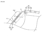
- FIG. 1 is an explanatory perspective view illustrating an illumination unit according to an embodiment.
- the illumination unit may include first and second reflectors 200 and 300, and at least one light source module 100 placed between the first and second reflectors 200 and 300.
- the light source module 100 may be located between the first reflector 200 and the second reflector 300 and may be located closer to the first reflector 200 than the second reflector 300.
- the light source module 100 may come into contact with the first reflector 200 while being spaced apart from the second reflector 300 by a predetermined distance, or may come into contact with the second reflector 300 while being spaced apart from the first reflector 200 by a predetermined distance.
- the light source module 100 may be spaced apart from the first reflector 200 and the second reflector 300 by predetermined distances, or may come into contact with both the first reflector 200 and the second reflector 300.
- the light source module 100 may include a board 100b having an electrode pattern, at least one light source 100a placed on the board 100b, and at least one connector 100c for electric connection with an external component.
- the light source 100a of the light source module 100 may be a top view type light emitting diode.
- the light source 100a may be a side view type light emitting diode.
- the board 100b may be a Printed Circuit Board (PCB) formed of any one material selected from among polyethyleneterephthalate (PET), glass, polycarbondate (PC), and silicon (Si), and may take the form of a film.
- PCB Printed Circuit Board
- a single layer PCB, a multilayer PCB, a ceramic board, a metal core PCB, or the like may be selectively used as the board 100b.
- the board 100b may be provided with any one of a reflective coating film and a reflective coating material layer, to reflect light emitted from the light source 100a to a central region of the reflector 300.
- the light source 100a may be a Light Emitting Diode (LED) chip.
- the LED chip may be a blue LED chip or an ultraviolet LED chip, or may be a package combining at least one or more selected from among a red LED chip, a green LED chip, a blue LED chip, a yellow green LED chip, and a white LED chip.
- a white LED may be realized by coupling a yellow phosphor to a blue LED, by coupling both red and green phosphors to a blue LED, or by coupling yellow, red and green phosphors to a blue LED.
- the first reflector 200 and the second reflector 300 may be spaced apart from each other by a predetermined distance so as to face each other, such that an air guide is defined in an empty space between the first reflector 200 and the second reflector 300.
- the first reflector 200 may have an open region, and may come into contact with one side of the light source module 100 or may be spaced apart from the light source module 100 by a predetermined distance.
- the first reflector 200 may have an open central region
- the light source module 100 may include a first light source module and a second light source module which are arranged at opposite edge regions of the first reflector 200 so as to face each other.
- the first reflector 200 may be formed of any one of a reflective coating film and a reflective coating material layer and may serve to reflect light emitted from the light source module 100 toward the second reflector 300.
- a saw-toothed reflective pattern may be formed on a surface of the first reflector 200 facing the light source module 100.
- the reflective pattern may be flat or may be curved.
- the reason for providing the surface of the first reflector 200 with the reflective pattern is to reflect light emitted from the light source module 100 toward the central region of the second reflector 300, thereby increasing luminance of the central region of the illumination unit.
- the second reflector 300 may include a bottom plate 310 and lateral plates 320.
- the lateral plates 320 may include a pair of first lateral plates 320a, which are arranged to face each other in a first direction (Y-direction of FIG. 2 ) of the bottom plate 310, and a pair of second lateral plates 320b which are arranged to face each other in a second direction (X-direction of FIG. 2 ) orthogonal to the first direction.
- the light source module 100 and the first reflector 200 may be placed over the first lateral plate 320a.
- the second lateral plate 320b may have a groove.
- the groove 110 may be formed in an upper surface 320b2 of the second lateral plate 320b and serve as a passage of a line that electrically connects the connector 100c of the light source module 100 and a drive unit to each other.
- At least one hole may be perforated in the groove 110.
- the drive unit to drive the light source module 100 may be located below the bottom plate 310 of the second reflector 300, and at least one line may pass through the groove 110 and the hole so as to electrically connect the light source module 100 and the drive unit to each other.
- the groove 110 may be located close to the connector 100c of the light source module 100.
- the second lateral plate 320b may have more than one first coupling portion 322 for coupling with an optical member and more than one second coupling portion 334 for coupling with a cover member.
- the first coupling portion 322 may be formed on the upper surface 320b2 of the second lateral plate 320b, and the second coupling portion 334 may be formed on an outer surface 320b3 of the second lateral plate 320b.
- first coupling portion 322 and the second coupling portion 334 may be provided to correspond to each other in a one to one ratio.
- the first coupling portion 322 may protrude upward (in Z-direction of FIG. 2 ) from the upper surface 320b2 of the second lateral plate 320b.
- the second coupling portion 334 may protrude in the second direction (X-direction of FIG. 2 ) from the outer surface 320b3 of the second lateral plate 320b.
- a reflective coating film or a deposited reflective coating material layer may be formed over an inner surface 320b1 of the second lateral plate 320b and the bottom plate 310.
- the same reflective material may be formed over the inner surface 320b1 of the second lateral plate 320b and the bottom plate 310, different materials may be formed as occasion demands.
- the bottom plate 310 of the second reflector 300 may be spaced apart from the light source module 100 by a predetermined distance and may have an inclined surface having a predetermined inclination angle with respect to a horizontal plane that is parallel to the surface of the first reflector 200.
- the inclined surface of the bottom plate 310 of the second reflector 300 may serve to reflect the light, emitted from the light source module 100 or reflected from the first reflector 200, toward the open region of the first reflector 200.
- the bottom plate 310 of the second reflector 300 may include at least two inclined surfaces having at least one inflection point.
- the first and second inclined surfaces which are located next to each other about the inflection point, may have different radii of curvature.
- the inflection point between the first and second inclined surfaces may be located close to the light source module 100.
- a reflective coating film or a deposited reflective coating material layer may be formed over an upper surface of the bottom plate 310 of the second reflector 300.
- the bottom plate 310 of the second reflector 300 may include at least one of a metal or metal oxide.
- the bottom plate 310 may be formed of a metal or metal oxide having high reflectivity, such as aluminum (Al), silver (Ag), gold (Au) or titanium dioxide (TiO 2 ).
- the bottom plate 310 of the second reflector 300 may be formed by depositing or coating a metal or metal oxide on the upper surface thereof, or may be formed by printing metallic ink.
- deposition may be performed by thermal deposition, evaporation, or vacuum deposition such as sputtering, and coating or printing may be performed by gravure coating, silk screen printing, or the like.
- the second reflector 300 may be provided with at least one of a specular-reflection sheet and a diffuse-reflection sheet.
- the first and second inclined surfaces may be formed of the same material or different materials and may have different surface roughness values.
- the first and second inclined surfaces may be formed of the same material, but may have different surface roughness values.
- the first and second inclined surfaces may be formed of different materials and may have different surface roughness values.
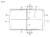
- FIG. 2 is a view illustrating a position of the groove according to a first embodiment.
- the second reflector 300 may include the bottom plate 310 and the lateral plates 320.
- the lateral plates 320 may include the first lateral plates 320a, which are arranged to face each other in the first direction (Y-direction of FIG. 2 ) of the bottom plate 310, and the second lateral plates 320b which are arranged to face each other in the second direction (X-direction of FIG. 2 ) orthogonal to the first direction.
- the light source module 100 and the first reflector 200 may be placed over the first lateral plate 320a.
- the light source module 100 may include the board 100b having an electrode pattern, the at least one light source 100a placed on the board 100b, and the at least one connector 100c for electric connection with an external component.
- the second lateral plate 320b may include the groove 110.
- the groove 110 may be formed in the upper surface 320b2 of the second lateral plate 320b and serve as a passage of a line that electrically connects the connector 100c of the light source module 100 and the drive unit to each other.
- the at least one hole 112 may be perforated in the groove 110.
- a line electrically connected to the connector 100c of the light source module 100 may pass through the groove 110 and the hole 112 to thereby be electrically connected to the drive unit below the bottom plate 310.
- the light source module 100 including the connector 100c may be placed on the first lateral plate 320a such that a portion of the connector 100c overlaps with the groove 110 of the second lateral plate 320b.
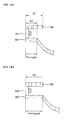
- FIGs. 3A and 3B are views illustrating electric connection between the light source module and the drive unit according to the first embodiment.
- FIG. 3A illustrates the groove viewed from the top
- FIG. 3B illustrates the groove viewed from the bottom.
- the light source module 100 may include the board 100b having the electrode pattern, the at least one light source 100a placed on the board 100b, and the at least one connector 100c for electric connection with an external component.
- the groove 110 may be formed in the upper surface 320b2 of the second lateral plate 320b and serve as a passage of a line 114 that electrically connects the connector 100c of the light source module 100 and the drive unit to each other.
- the at least one hole 112 may be perforated in the groove 110.
- the drive unit 370 to drive the light source module 100 may be located below the bottom plate 310 of the second reflector 300, and the at least one line 114 may pass through the groove 110 and the hole 112 so as to electrically connect the light source module 100 and the drive unit 370 to each other.
- the groove 110 may be located close to the connector 100c of the light source module 100.
- FIG. 4 is a sectional view taken along the line I-I of FIG. 3A .
- the groove 110 may be formed in the upper surface 320b2 of the second lateral plate 320b and serve as a passage of the line 114 that electrically connects the connector 100c of the light source module 100 and the drive unit 370 to each other.
- the groove 110 may be defined by a bottom surface 110a and a lateral surface 110b.
- the lateral surface 110b of the groove 110 may be a flat surface orthogonal to the bottom surface 110a.
- the lateral surface 110b of the groove 110 may be inclined with respect to the bottom surface 110a.
- the groove 110 may have a width w and a depth d which differ from each other.
- the width w of the groove 110 may be less than the depth d of the groove 110.
- the groove may have a width w and a depth d that are equal to each other.
- the single line 114 may be placed in the groove 110, a plurality of lines 114 may be stacked one above another in the groove 110.
- the depth d of the groove 110 may be determined based on the number of the lines 114.
- FIGs. 5A and 5B are sectional views taken along the line II-II of FIG. 3A .
- the second lateral plate 320b may have the groove 110 and the hole 112, which serve as a passage of the line that electrically connects the connector of the light source module and the drive unit to each other.
- a width w1 of the groove 110 may differ from a width w2 of the hole 112.
- the width w1 of the groove 110 may be greater than the width w2 of the hole 112.
- FIG. 5A is applicable to embodiments in which some of the plurality of lines placed in the groove 110 pass through the hole 112.
- the width w1 of the groove 110 may be equal to the width w2 of the hole 112.
- the width w1 of the groove 110 and the width w2 of the hole 112 may be determined based on various arrangements of the lines.
- a plurality of different holes 112 may be formed in the single groove 110.
- FIGs. 6A to 6D are sectional views illustrating different shapes of the groove.
- the second lateral plate 320b has the groove 110 that serves as a passage of a line that electrically connects the connector 100c of the light source module and the drive unit to each other.
- the groove 110 may include first and second lateral surfaces 110b1 and 110b2 facing each other, and the bottom surface 110a located between the first and second lateral surfaces 110b1 and 110b2.
- a first angle ⁇ 1 between the first lateral surface 110b1 and the bottom surface 110a and a second angle ⁇ 2 between the second lateral surface 110b2 and the bottom surface 110a may be an acute angle.
- first angle ⁇ 1 and the second angle ⁇ 2 may differ from each other, but may be equal to each other as occasion demands.
- the first angle ⁇ 1 may be a right angle and the second angle ⁇ 2 may be an acute angle as illustrated in FIG. 6B , or the first angle ⁇ 1 may be an acute angle and the second angle ⁇ 2 may be a right angle as illustrated in FIG. 6C .
- the first lateral surface 110b1 may be a curved surface having a first radius of curvature R1
- the second lateral surface 110b2 may be a curved surface having a second radius of curvature R2.
- the first radius of curvature R1 and the second radius of curvature R2 may differ from each other, but may be equal to each other, as occasion demands.
- the reason for providing the groove 110 with a wider bottom end and a narrower top end is to prevent the line(s) placed in the groove 110 from being visible from the outside, thereby enabling fabrication of an illumination unit having a pleasant outer appearance and preventing damage to the line(s) due to external shock.
- FIGs. 7 and 8 are views illustrating a position of the groove according to a second embodiment.
- FIG. 7 is a plan view illustrating the top of the groove
- FIG. 8 is a view illustrating the bottom of the groove.
- FIG. 2 illustrates one embodiment of a position of the groove 110 in a configuration in which the connector 100c of the light source module 100 is located at one side of the board 100b
- FIGs. 7 and 8 illustrate another embodiment of a position of the groove 110 in a configuration in which a pair of connectors 100c of the light source module 100 is arranged respectively at both sides of the board 100b.
- the second reflector 300 may include the bottom plate 310 and the lateral plates 320.
- the lateral plates 320 may include the first lateral plates 320a, which are arranged to face each other in the first direction (Y-direction of FIG. 2 ) of the bottom plate 310, and the second lateral plates 320b which are arranged to face each other in the second direction (X-direction of FIG. 2 ) orthogonal to the first direction.
- the light source module 100 may be placed on the first lateral plate 320a.
- the light source module 100 may include the board 100b having the electrode pattern, the at least one light source 100a placed on the board 100b, and the at least one connector 100c for electric connection with an external component.
- the connectors 100c of the light source module 100 may be located respectively at both sides of the board 100b.
- the second lateral plate 320b may have the groove 110 formed in the upper surface 320b2 thereof, and the groove 110 serves as a passage of a line that electrically connects a corresponding one of the connectors 100c of the light source module 100 and the drive unit to each other.
- the at least one hole 112 may be perforated in the groove 110.
- the drive unit 370 to drive the light source module 100 may be located below the bottom plate 310 of the second reflector 300, and the at least one line 114 may pass through the groove 110 and the hole 112 so as to electrically connect the light source module 100 and the drive unit 370 to each other.
- the groove 110 may be located close to the corresponding connector 100c of the light source module 100.
- the groove 110 may be formed in each of the second lateral plates 320b arranged to face each other.
- FIGs. 9 and 10 are views illustrating a position of the groove according to a third embodiment.
- FIG. 9 is a plan view illustrating the top of the groove
- FIG. 10 is a view illustrating the bottom of the groove.
- FIG. 2 illustrates one embodiment of a position of the groove 110 in a configuration in which the connector 100c of the light source module 100 is located at one side of the board 100b
- FIGs. 7 and 8 illustrate another embodiment of a position of the groove 110 in a configuration in which a pair of connectors 100c of the light source module 100 is arranged respectively at both sides of the board 100b
- FIGs. 9 and 10 illustrate the other embodiment of a position of the groove 110 in a configuration in which the connector 100c of the light source module 100 is located at the center of the board 100b.
- the second reflector 300 may include the bottom plate 310 and the lateral plates 320.
- the lateral plates 320 may include the first lateral plates 320a, which are arranged to face each other in the first direction (Y-direction of FIG. 2 ) of the bottom plate 310, and the second lateral plates 320b which are arranged to face each other in the second direction (X-direction of FIG. 2 ) orthogonal to the first direction.
- the light source module 100 may be placed on the first lateral plate 320a.
- the light source module 100 may include the board 100b having the electrode pattern, the at least one light source 100a placed on the board 100b, and the at least one connector 100c for electric connection with an external component.
- the connector 100c of the light source module 100 may be located at the center of the board 100b.
- the bottom plate 310 located close to the connector 100c of the light source module 100 may have the groove 110 that serves as a passage of a line that electrically connects the connector 100c of the light source module 100 and the drive unit to each other.
- the at least one hole 112 may be perforated in the groove 110.
- the drive unit 370 to drive the light source module 100 may be located below the bottom plate 310 of the second reflector 300, and the at least one line 114 may pass through the groove 110 and the hole 112 so as to electrically connect the light source module 100 and the drive unit 370 to each other.
- the groove 110 may be located close to the connector 100c of the light source module 100.
- the groove 110 may be formed in the bottom plate 310.
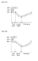
- FIG. 11 is a view illustrating an inclined surface of the second reflector according to a first embodiment.
- the light source module 100 is located between the first and second reflectors 200 and 300.
- the second reflector 300 may include at least one inclined surface and at least one flat surface.
- the flat surface of the second reflector 300 may be located close to the light source module 100 and may be parallel to the first reflector 200.
- the inclined surface of the second reflector 300 may include at least one inflection point. That is, inclined surfaces, which are located next to each other about the inflection point, may have different radii of curvature.
- the second reflector 300 may include first, second, and third regions.
- the first region may be aligned with the light source module 100 and the first reflector 200, and may be a flat surface parallel to the first reflector 200.
- the second region which is located between the first region and the third region, may be a first inclined surface that is inclined downward from the first region.
- the third region which is located next to the second region, may be a second inclined surface that is inclined upward from the second region.
- the first inclined surface of the second region and the second inclined surface of the third region may be located next to each other about an inflection point P.
- first inclined surface of the second region may be a curved surface having a first radius of curvature R1
- second inclined surface of the third region may be a curved surface having a second radius of curvature R2.
- the first radius of curvature R1 and the second radius of curvature R2 may differ from each other, and the first radius of curvature R1 may be greater than the second radius of curvature R2.
- the first radius of curvature R1 and the second radius of curvature R2 may be equal to each other.
- At least one of the first inclined surface of the second region and the second inclined surface of the third region may be a convexly curved surface or a concavely curved surface.
- the first inclined surface of the second region may be a flat surface having a first gradient and the second inclined surface of the third region may be a flat surface having a second gradient.
- first gradient and the second gradient may differ from each other, and the first gradient may be greater than the second gradient.
- the first region of the second reflector 300 may be provided with a specular-reflection sheet.
- the second region and the third region of the second reflector 300 may be provided with at least one of a specular-reflection sheet and a diffuse-reflection sheet.
- the specular-reflection sheet formed on the first region of the second reflector 300 serves to reflect light to a low luminance central region of the second reflector 300, which achieves uniform luminance.
- first region of the second reflector 300 is the flat surface parallel to the first reflector 200, concentrating a greater quantity of light emitted from the light source module 100 on the low-luminance central region of the second reflector 300 may increase luminance at a central region of the illumination unit.
- the second reflector 300 may be formed of a metal or metal oxide having high reflectivity, such as aluminum (Al), silver (Ag), gold (Au) or titanium dioxide (TiO 2 )
- the first, second and third regions of the second reflector 300 may be formed of the same material or different materials, and may have different surface roughness values.
- first, second and third regions of the second reflector 300 may be formed of the same material, but may have different surface roughness values.
- first, second and third regions of the second reflector 300 may be formed of different materials and may have different surface roughness values.
- FIGs. 12A to 12C are explanatory views illustrating an arrangement relationship between the light source module and the first and second reflectors.
- FIG. 12A illustrates the light source module 100 spaced apart from the first reflector 200 and the second reflector 300 by predetermined distances.
- FIG. 12B illustrates the light source module 100 coming into contact with the first reflector 200 while being spaced apart from the second reflector 300 by a predetermined distance.
- FIG. 12C illustrates the light source module 100 coming into contact with both the first reflector 200 and the second reflector 300.
- the light source module 100 may be spaced apart from the first reflector 200 by a first distance d1 and may be spaced apart from the second reflector 300 by a second distance d2.
- first distance d1 and the second distance d2 may be equal to each other, or may differ from each other.
- the first distance d1 may be less than the second distance d2.
- the light source module 100 may come into contact with the first reflector 200 and may be spaced apart from the second reflector 300 by a distance d.
- the light source module 100 comes into contact with the first reflector 200, it is possible to prevent a hot spot phenomenon and to transmit light more distantly from the light source module 100.
- the light source module 100 may come into contact with both the first reflector 200 and the second reflector 300.
- the light source module 100 comes into contact with both the first reflector 200 and the second reflector 300, it is possible to prevent a hot spot phenomenon, to transmit light more distantly from the light source module 100, and to reduce a thickness of the entire illumination unit.
- FIGs. 13A and 13B are views comparing a width of the first region of the second reflector with a width of the first reflector.
- the first region of the second reflector 300 may overlap with the first reflector 200, and a width W2 of the first region of the second reflector 300 may be less than a width W1 of the first reflector 200.
- the light may be concentrated on the low luminance central region of the second reflector 300.
- the first region of the second reflector 300 may completely overlap with the first reflector 200, and a width of the first region of the second reflector 300 may be equal to a width W1 of the first reflector 200.
- FIGs. 14A to 14D are views illustrating different inclined surfaces for the second reflector.
- the second reflector 300 may include the first, second and third regions.
- the first region may be aligned with the light source module 100 and the first reflector 200 and may be a flat surface parallel to the first reflector 200.
- the second region which is located between the first region and the third region, may be a first inclined surface that is inclined downward from the first region.
- the third region which is located next to the second region, may be a second inclined surface that is inclined upward from the second region.
- the first inclined surface may be a curved surface having a first radius of curvature
- the second inclined surface may be a curved surface having a second radius of curvature.
- the first radius of curvature and the second radius of curvature may differ from each other.
- At least one of the first and second inclined surfaces may be a convexly curved surface or a concavely curved surface.
- the second reflector 300 may include the first, second and third regions.
- the first region may be aligned with the light source module 100 and the first reflector 200 and may be a flat surface parallel to the first reflector 200.
- the second region which is located between the first region and the third region, may be a first inclined surface that is inclined downward from the first region.
- the third region which is located next to the second region, may be a second inclined surface that is inclined upward from the second region.
- the first inclined surface may be a flat surface having a first gradient
- the second inclined surface may be a flat surface having a second gradient.
- the first gradient and the second gradient may differ from each other.
- the second reflector 300 may include the first, second and third regions.
- the first region may be aligned with the light source module 100 and the first reflector 200 and may be a flat surface parallel to the first reflector 200.
- the second region which is located between the first region and the third region, may be a first inclined surface that is inclined downward from the first region.
- the third region which is located next to the second region, may be a second inclined surface that is inclined upward from the second region.
- the first inclined surface may be a curved surface having a predetermined radius of curvature
- the second inclined surface may be a flat surface having a predetermined gradient
- the second reflector 300 may include the first, second and third regions.
- the first region may be aligned with the light source module 100 and the first reflector 200 and may be a flat surface parallel to the first reflector 200.
- the second region which is located between the first region and the third region, may be a first inclined surface that is inclined downward from the first region.
- the third region which is located next to the second region, may be a second inclined surface that is inclined upward from the second region.
- the first inclined surface may be a flat surface having a predetermined gradient
- the second inclined surface may be a curved surface having a predetermined radius of curvature
- FIG. 15 is a view illustrating an inclined surface of the second reflector according to a second embodiment.
- FIG. 15 illustrates a configuration similar to that of FIG. 11 , there is a difference in that a fourth region may be formed next to the third region of the second reflector 300.
- the second reflector 300 may include a center fourth region next to the third region.
- the fourth region may be a flat surface parallel to the first reflector 200, or may be a curved surface having a third radius of curvature.
- the fourth region is located at the center of the second reflector 300.
- the fourth region may have a gentle shape to provide uniform luminance because a sharp shape of the fourth region causes a hot spot phenomenon due to light concentration.
- FIGs. 16A to 16C are views illustrating the fourth region of FIG. 15 .
- the fourth region of the second reflector 300 may be a flat surface parallel to the first reflector.
- the fourth region of the second reflector 300 may be a concavely curved surface having a third radius of curvature R3.
- the fourth region of the second reflector 300 may be a convexly curved surface having a third radius of curvature R3.
- fabricating the fourth region with a gentle shape without a pointed portion may reduce a hot spot phenomenon and achieve uniform luminance.
- the light source module 100 and the first and second reflectors 200 and 300 arranged as described above may be supported by a cover frame.
- FIGs. 17A to 17D are views illustrating the first reflector having an inclined surface.
- FIG. 17A illustrates a flat inclined surface
- FIGs. 17B , 17C and 17D illustrate a curved inclined surface.
- one surface of the first reflector 200 facing the second reflector 300 may be inclined with respect to the other surface of the first reflector 200 by a predetermined angle.
- the angle ⁇ of the inclined surface may be in a range of 1-85 degrees with respect to a horizontal plane parallel to the other surface of the first reflector 200.
- a thickness of the first reflector 200 may gradually decrease or increase with increasing distance from the light source module 100.
- a thickness t1 of a region of the first reflector 200 close to the light source module 100 may differ from a thickness t2 of a region of the first reflector 200 distant from the light source module 100. As illustrated in FIGs. 17A and 17B , the thickness t1 of the region of the first reflector 200 close to the light source module 100 may be greater than the thickness t2 of the region of the first reflector 200 distant from the light source module 100.
- the thickness t1 of the region of the first reflector 200 close to the light source module 100 may be less than the thickness t2 of the region of the first reflector 200 distant from the light source module 100.
- the first reflector 200 may include not only an inclined surface, but also a flat surface.
- the region of the first reflector 200 close to the light source module 100 may include an inclined surface, and the region of the first reflector 200 distant from the light source module 100 may include a flat surface.
- a length L1 of the inclined surface and a length L2 of the flat surface may be equal to each other, or may differ from each other, as occasion demands.
- a reflective pattern may be formed on a surface of the first reflector 200.
- FIGs. 18A to 18D are views illustrating the first reflector having a reflective pattern.
- FIG. 18A illustrates a saw-toothed reflective pattern 220, each tooth of which may have a flat surface.
- FIGs. 18B and 18C illustrate a saw-toothed reflective pattern 220, each tooth of which may have a curved surface.
- the reflective pattern 220 illustrated in FIG. 18B has saw teeth of a concavely curved surface
- the reflective pattern 220 illustrated in FIG. 18C has saw teeth of a convexly curved surface.
- the size of teeth may gradually increase with increasing distance from a fixed end of the first reflector 200.
- Providing the reflective pattern 220 on the first reflector 200 may achieve higher reflectivity and uniform diffusion of light.
- various sizes of the reflective pattern 220 may be formed at a corresponding region based on luminance distribution of the entire illumination unit.
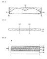
- FIG. 19 is a sectional view illustrating an illumination unit including an optical member
- FIG. 20 is a sectional view illustrating the optical member of FIG. 19 .
- an optical member 600 may be spaced apart from the second reflector 300 by a predetermined distance.
- an air guide may be defined in a space between the second reflector 300 and the optical member 600.
- the optical member 600 as illustrated in FIG. 20 , may have a roughened pattern 620 formed on an upper surface thereof.
- the optical member 600 serves to diffuse light emitted from the light source module 100.
- the roughened pattern 620 may be formed on the upper surface of the optical member 600.
- the optical member 600 may have a multilayer form.
- the roughened pattern 620 may be an uppermost layer or any one layer of the optical member 600.
- the roughened pattern 620 may have a stripe shape extending along the light source module 100.
- the roughened pattern 620 may include ridges formed on the surface of the optical member 600.
- the respective ridges may have a first face and a second face facing each other, and an angle between the first face and the second face may be an acute angle or an obtuse angle.
- the optical member 600 may be formed of at least one sheet. More specifically, the optical member 600 may selectively include a diffusion sheet, a prism sheet, a luminance-increasing sheet, or the like.
- the diffusion sheet functions to diffuse light emitted from a light source
- the prism sheet functions to guide diffused light to a light emitting region
- the luminance-increasing sheet functions to increase luminance
- the second reflector 300 may include at least one of a metal or a metal oxide.
- the second reflector 300 may be formed of a metal or metal oxide having high reflectivity, such as aluminum (Al), silver (Ag), gold (Au) or titanium dioxide (TiO 2 )
- the second reflector 300 may be formed of any one of a reflective coating film and a reflective coating material layer.
- the second reflector 300 may serve to reflect light emitted from the light source module 100 toward the optical member 600.
- a saw-toothed reflective pattern may be formed on a surface of the second reflector 300 facing the optical member 600.
- the reflective pattern may be flat or may be curved.
- the reason for providing the surface of the second reflector 300 with the reflective pattern is to uniformly diffuse and reflect light emitted from the light source module 100.
- the aforementioned embodiments may achieve low weight and manufacturing costs and uniform luminance.
- the illumination unit may achieve enhanced reliability and economical efficiency and may be suitable for a wide indoor space.
- an illumination system may include a lamp, and a street lamp.
- FIG. 21 is a view illustrating a display module having an illumination unit according to an embodiment.
- the display module 20 may include a display panel 800 and an illumination unit 700.
- the display panel 800 may include a color filter substrate 810 and a Thin Film Transistor (TFT) substrate 820, which are bonded to face each other with a uniform cell gap therebetween.
- a liquid crystal layer (not shown) may be interposed between the two substrates 810 and 820.
- An upper polarizer 830 and a lower polarizer 840 may be disposed at upper and lower sides of the display panel 800. More specifically, the upper polarizer 830 may be disposed on an upper surface of the color filter substrate 810, and the lower polarizer 840 may be disposed beneath a lower surface of the TFT substrate 820.
- a gate and data drive unit may be provided at a lateral surface of the display panel 800 and may generate a drive signal to drive the panel 800.
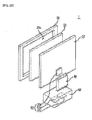
- FIGs. 22 and 23 are views illustrating a display apparatus according to an embodiment.
- the display apparatus 1 may include the display module 20, a front cover 30 and a back cover 35 to surround the display module 20, a drive unit 55 provided at the back cover 35, and a drive unit cover 40 to surround the drive unit 55.
- the front cover 30 may include a transparent front panel (not shown) to transmit light.
- the front panel serves to protect the display module 20 spaced apart therefrom by a predetermined distance and to transmit light emitted from the display module 20, allowing an image displayed on the display module 20 to be seen from the outside.
- the back cover 35 may be coupled to the front cover 30 to protect the display module 20.
- the drive unit 55 may be placed on a surface of the back cover 35.
- the drive unit 55 may include a drive controller 55a, a main board 55b and a power supply board 55c.
- the drive controller 55a may be a timing controller.
- the drive controller 55a serves to adjust an operation timing of each driver IC of the display module 20.
- the main board 55b may serve to transmit V-sync, H-sync and R, G and B resolution signals to the timing controller.
- the power supply board 55c supplies power to the display module 20.
- the drive unit 55 may be attached to the back cover 35 and may be enclosed by the drive unit cover 40.
- the back cover 35 has a plurality of holes, through which the display module 20 may be connected to the drive unit 55. Also, a stand 60 to support the display apparatus 1 may be provided.
- the drive controller 55a of the drive unit 55 may be provided at the back cover 35, whereas the main board 55b and the power supply board 55c may be provided in the stand 60.
- the drive unit cover 40 may be configured to enclose only the drive unit 55 provided at the back cover 35.
- the present embodiment illustrates the main board 55b and the power supply board 55c as being provided separately, they may be integrated with each other, and the disclosure is not limited thereto.
- a backlight unit which include the groove, the first and second reflectors and the light source module as described in the aforementioned embodiments, may be realized.
- the illumination system may include a lamp or a street lamp.
Description
- Embodiments relate to an illumination unit and a display apparatus using the same.
- In general, downlights are constructed such that a light source is embedded in a ceiling hole. Such downlights have been widely used as architectural illumination means that integrate illumination with a building.
- The downlight is embedded in the ceiling so as to be substantially prevented from being exposed outward, thus advantageously providing an orderly external appearance to the ceiling. Moreover, the downlight embedded in the ceiling may have low luminance and be suitable to form an intimate indoor space.
- However, such an illumination unit configuration may be suitable for a narrow indoor space than a wide indoor space, and may need a great number of light sources such as Light Emitting Diodes (LEDs).
- Document
US 2011/211335 is considered the closest prior art. - Accordingly, in the future, development of an illumination unit suitable for a wide indoor space even with a low number of LEDs is necessary.
- Embodiments provide an illumination unit which includes a reflector partially provided with an inclined surface and is suitable for a wide indoor space, and a display apparatus using the same.
- The illumination unit includes first and second reflectors, and at least one light source module placed between the first and second reflectors, wherein the second reflector includes a bottom plate, first lateral plates arranged to face each other in a first direction of the bottom plate, the light source module being placed on each of the first lateral plates; second lateral plates arranged to face each other in a second direction orthogonal to the first direction, a groove formed in at least one of the second lateral plate and the bottom plate, and at least one hole formed in the groove.
- The light source module is placed on the first lateral plate of the second reflector, and may include at least one connector for electric connection with an external component.
- In this case, the groove may be located close to the connector.
- The illumination unit may further include at least one drive unit placed below the bottom plate of the second reflector and serving to drive the light source module, and at least one line placed through the groove and the hole to electrically connect the light source module and the drive unit to each other.
- The groove may have a width and a depth which differ from each other, and the width of the groove may be less than the depth of the groove.
- The width of the groove may differ from the width of the hole, and the width of the groove may be greater than the width of the hole.
- The width of the groove may be equal to the width of the hole.
- The groove may include first and second lateral surfaces facing each other, and a bottom surface located between the first and second lateral surfaces, and a first angle between the first lateral surface and the bottom surface and a second angle between the second lateral surface and the bottom surface may be an acute angle.
- Here, the first angle and the second angle may differ from each other. The first angle may be a right angle and the second angle may be an acute angle. Alternatively, the first angle may be an acute angle and the second angle may be a right angle.
- The first lateral surface may be a curved surface having a first radius of curvature, the second lateral surface may be a curved surface having a second radius of curvature, and the first radius of curvature and the second radius of curvature may differ from each other.
- The bottom plate of the second reflector may include at least one inclined surface.
- The at least one inclined surface may include at least one inflection point such that inclined surfaces, which are located next to each other about the inflection point, have different radii of curvature.
- The light source module may be spaced apart from the first reflector by a first distance, and may be spaced apart from the second reflector by a second distance. The first distance and the second distance may differ from each other.
- The light source module may come into contact with at least one of the first and second reflectors.
- A thickness of a region of the first reflector close to the light source module may differ from a thickness of a region of the first reflector distant from the light source module, and the first reflector may include a reflective pattern formed on a surface thereof facing the light source module.
- The first reflector and the second reflector may be formed of different materials.
- In another embodiment, an illumination unit includes a bottom plate, first lateral plates arranged to face each other in a first direction of the bottom plate, second lateral plates arranged to face each other in a second direction orthogonal to the first direction, a groove formed in at least one of the second lateral plate and the bottom plate, and at least one hole formed in the groove, wherein the light source module including a connector is placed on the first lateral plate, and a portion of the connector overlaps with the groove of the second lateral plate.
- Arrangements and embodiments may be described in detail with reference to the following drawings in which like reference numerals refer to like elements and wherein:
-
FIG. 1 is an explanatory perspective view illustrating an illumination unit according to an embodiment; -
FIG. 2 is a view illustrating a position of a groove according to a first embodiment; -
FIGs. 3A and3B are views illustrating electric connection between a light source module and a drive unit according to the first embodiment; -
FIG. 4 is a sectional view taken along the line I-I ofFIG. 3A ; -
FIGs. 5A and5B are sectional views taken along the line II-II ofFIG. 3A ; -
FIGs. 6A to 6D are sectional views illustrating different shapes of the groove; -
FIGs. 7 and8 are views illustrating a position of the groove according to a second embodiment; -
FIGs. 9 and10 are views illustrating positions of recesses according to a third embodiment; -
FIG. 11 is a view illustrating an inclined surface of a second reflector according to a first embodiment; -
FIGs. 12A to 12C are explanatory views illustrating an arrangement relationship between a light source module and first and second reflectors; -
FIGs. 13A and 13B are views comparing a width of a first region of the second reflector with a width of the first reflector; -
FIGs. 14A to 14D are views illustrating different inclined surfaces for the second reflector; -
FIG. 15 is a view illustrating an inclined surface of a second reflector according to a second embodiment; -
FIGs. 16A to 16C are views illustrating a fourth region ofFIG. 15 ; -
FIGs. 17A to 17D are views illustrating a first reflector having an inclined surface; -
FIGs. 18A to 18D are views illustrating a first reflector having a reflective pattern; -
FIG. 19 is a sectional view illustrating an illumination unit including an optical member; -
FIG. 20 is a sectional view illustrating the optical member ofFIG. 19 ; -
FIG. 21 is a view illustrating a display module having an illumination unit according to an embodiment; and -
FIGs. 22 and23 are views illustrating a display apparatus according to an embodiment. - Hereinafter, embodiments will be described with reference to the annexed drawings.
- It will be understood that when an element is referred to as being 'on' or "under" another element, it can be directly on/under the element, and one or more intervening elements may also be present.
- Also, when an element is referred to as being 'on' or 'under', 'under the element' as well as 'on the element' can be included based on the element.
-
FIG. 1 is an explanatory perspective view illustrating an illumination unit according to an embodiment. - As illustrated in
FIG. 1 , the illumination unit may include first andsecond reflectors light source module 100 placed between the first andsecond reflectors - The
light source module 100 may be located between thefirst reflector 200 and thesecond reflector 300 and may be located closer to thefirst reflector 200 than thesecond reflector 300. - As occasion demands, the
light source module 100 may come into contact with thefirst reflector 200 while being spaced apart from thesecond reflector 300 by a predetermined distance, or may come into contact with thesecond reflector 300 while being spaced apart from thefirst reflector 200 by a predetermined distance. - Alternatively, the
light source module 100 may be spaced apart from thefirst reflector 200 and thesecond reflector 300 by predetermined distances, or may come into contact with both thefirst reflector 200 and thesecond reflector 300. - The
light source module 100 may include aboard 100b having an electrode pattern, at least onelight source 100a placed on theboard 100b, and at least oneconnector 100c for electric connection with an external component. - The
light source 100a of thelight source module 100 may be a top view type light emitting diode. - As occasion demands, the
light source 100a may be a side view type light emitting diode. - The
board 100b may be a Printed Circuit Board (PCB) formed of any one material selected from among polyethyleneterephthalate (PET), glass, polycarbondate (PC), and silicon (Si), and may take the form of a film. - A single layer PCB, a multilayer PCB, a ceramic board, a metal core PCB, or the like may be selectively used as the
board 100b. - The
board 100b may be provided with any one of a reflective coating film and a reflective coating material layer, to reflect light emitted from thelight source 100a to a central region of thereflector 300. - The
light source 100a may be a Light Emitting Diode (LED) chip. The LED chip may be a blue LED chip or an ultraviolet LED chip, or may be a package combining at least one or more selected from among a red LED chip, a green LED chip, a blue LED chip, a yellow green LED chip, and a white LED chip. - A white LED may be realized by coupling a yellow phosphor to a blue LED, by coupling both red and green phosphors to a blue LED, or by coupling yellow, red and green phosphors to a blue LED.
- The
first reflector 200 and thesecond reflector 300 may be spaced apart from each other by a predetermined distance so as to face each other, such that an air guide is defined in an empty space between thefirst reflector 200 and thesecond reflector 300. - The
first reflector 200 may have an open region, and may come into contact with one side of thelight source module 100 or may be spaced apart from thelight source module 100 by a predetermined distance. - More specifically, the
first reflector 200 may have an open central region, and thelight source module 100 may include a first light source module and a second light source module which are arranged at opposite edge regions of thefirst reflector 200 so as to face each other. - The
first reflector 200 may be formed of any one of a reflective coating film and a reflective coating material layer and may serve to reflect light emitted from thelight source module 100 toward thesecond reflector 300. - A saw-toothed reflective pattern may be formed on a surface of the
first reflector 200 facing thelight source module 100. The reflective pattern may be flat or may be curved. - The reason for providing the surface of the
first reflector 200 with the reflective pattern is to reflect light emitted from thelight source module 100 toward the central region of thesecond reflector 300, thereby increasing luminance of the central region of the illumination unit. - The
second reflector 300 may include abottom plate 310 andlateral plates 320. - The
lateral plates 320 may include a pair offirst lateral plates 320a, which are arranged to face each other in a first direction (Y-direction ofFIG. 2 ) of thebottom plate 310, and a pair of secondlateral plates 320b which are arranged to face each other in a second direction (X-direction ofFIG. 2 ) orthogonal to the first direction. - The
light source module 100 and thefirst reflector 200 may be placed over the firstlateral plate 320a. - The second
lateral plate 320b may have a groove. - More specifically, the
groove 110 may be formed in an upper surface 320b2 of the secondlateral plate 320b and serve as a passage of a line that electrically connects theconnector 100c of thelight source module 100 and a drive unit to each other. - Here, at least one hole may be perforated in the
groove 110. - As such, the drive unit to drive the
light source module 100 may be located below thebottom plate 310 of thesecond reflector 300, and at least one line may pass through thegroove 110 and the hole so as to electrically connect thelight source module 100 and the drive unit to each other. - Through the aforementioned line connection, the
groove 110 may be located close to theconnector 100c of thelight source module 100. - The second
lateral plate 320b may have more than onefirst coupling portion 322 for coupling with an optical member and more than onesecond coupling portion 334 for coupling with a cover member. - The
first coupling portion 322 may be formed on the upper surface 320b2 of the secondlateral plate 320b, and thesecond coupling portion 334 may be formed on an outer surface 320b3 of the secondlateral plate 320b. - In this case, the
first coupling portion 322 and thesecond coupling portion 334 may be provided to correspond to each other in a one to one ratio. - The
first coupling portion 322 may protrude upward (in Z-direction ofFIG. 2 ) from the upper surface 320b2 of the secondlateral plate 320b. Thesecond coupling portion 334 may protrude in the second direction (X-direction ofFIG. 2 ) from the outer surface 320b3 of the secondlateral plate 320b. - A reflective coating film or a deposited reflective coating material layer may be formed over an inner surface 320b1 of the second
lateral plate 320b and thebottom plate 310. - Although the same reflective material may be formed over the inner surface 320b1 of the second
lateral plate 320b and thebottom plate 310, different materials may be formed as occasion demands. - The
bottom plate 310 of thesecond reflector 300 may be spaced apart from thelight source module 100 by a predetermined distance and may have an inclined surface having a predetermined inclination angle with respect to a horizontal plane that is parallel to the surface of thefirst reflector 200. - The inclined surface of the
bottom plate 310 of thesecond reflector 300 may serve to reflect the light, emitted from thelight source module 100 or reflected from thefirst reflector 200, toward the open region of thefirst reflector 200. - The
bottom plate 310 of thesecond reflector 300 may include at least two inclined surfaces having at least one inflection point. - In the
bottom plate 310 of thesecond reflector 300, the first and second inclined surfaces, which are located next to each other about the inflection point, may have different radii of curvature. - The inflection point between the first and second inclined surfaces may be located close to the
light source module 100. - This is because the radius of curvature of the first inclined surface close to the
light source module 100 is greater than the radius of curvature of the second inclined surface. - A reflective coating film or a deposited reflective coating material layer may be formed over an upper surface of the
bottom plate 310 of thesecond reflector 300. - Accordingly, the
bottom plate 310 of thesecond reflector 300 may include at least one of a metal or metal oxide. For example, thebottom plate 310 may be formed of a metal or metal oxide having high reflectivity, such as aluminum (Al), silver (Ag), gold (Au) or titanium dioxide (TiO2). - In this case, the
bottom plate 310 of thesecond reflector 300 may be formed by depositing or coating a metal or metal oxide on the upper surface thereof, or may be formed by printing metallic ink. - Here, deposition may be performed by thermal deposition, evaporation, or vacuum deposition such as sputtering, and coating or printing may be performed by gravure coating, silk screen printing, or the like.
- As occasion demands, the
second reflector 300 may be provided with at least one of a specular-reflection sheet and a diffuse-reflection sheet. - In the
bottom plate 310 of thesecond reflector 300, the first and second inclined surfaces may be formed of the same material or different materials and may have different surface roughness values. - More specifically, in the
bottom plate 310 of thesecond reflector 300, the first and second inclined surfaces may be formed of the same material, but may have different surface roughness values. - Alternatively, in the
bottom plate 310 of thesecond reflector 300, the first and second inclined surfaces may be formed of different materials and may have different surface roughness values. -
FIG. 2 is a view illustrating a position of the groove according to a first embodiment. - As illustrated in
FIG. 2 , thesecond reflector 300 may include thebottom plate 310 and thelateral plates 320. - The
lateral plates 320 may include thefirst lateral plates 320a, which are arranged to face each other in the first direction (Y-direction ofFIG. 2 ) of thebottom plate 310, and the secondlateral plates 320b which are arranged to face each other in the second direction (X-direction ofFIG. 2 ) orthogonal to the first direction. - The
light source module 100 and thefirst reflector 200 may be placed over the firstlateral plate 320a. - The
light source module 100 may include theboard 100b having an electrode pattern, the at least onelight source 100a placed on theboard 100b, and the at least oneconnector 100c for electric connection with an external component. - The second
lateral plate 320b may include thegroove 110. - More specifically, the
groove 110 may be formed in the upper surface 320b2 of the secondlateral plate 320b and serve as a passage of a line that electrically connects theconnector 100c of thelight source module 100 and the drive unit to each other. - The at least one
hole 112 may be perforated in thegroove 110. - As such, if the drive unit to drive the
light source module 100 is located below thebottom plate 310 of thesecond reflector 300, a line electrically connected to theconnector 100c of thelight source module 100 may pass through thegroove 110 and thehole 112 to thereby be electrically connected to the drive unit below thebottom plate 310. - The
light source module 100 including theconnector 100c may be placed on the firstlateral plate 320a such that a portion of theconnector 100c overlaps with thegroove 110 of the secondlateral plate 320b. -
FIGs. 3A and3B are views illustrating electric connection between the light source module and the drive unit according to the first embodiment.FIG. 3A illustrates the groove viewed from the top, andFIG. 3B illustrates the groove viewed from the bottom. - As illustrated in
FIG. 3A , thelight source module 100 may include theboard 100b having the electrode pattern, the at least onelight source 100a placed on theboard 100b, and the at least oneconnector 100c for electric connection with an external component. - The
groove 110 may be formed in the upper surface 320b2 of the secondlateral plate 320b and serve as a passage of aline 114 that electrically connects theconnector 100c of thelight source module 100 and the drive unit to each other. - The at least one
hole 112 may be perforated in thegroove 110. - As illustrated in
FIG. 3B , thedrive unit 370 to drive thelight source module 100 may be located below thebottom plate 310 of thesecond reflector 300, and the at least oneline 114 may pass through thegroove 110 and thehole 112 so as to electrically connect thelight source module 100 and thedrive unit 370 to each other. - As such, the
groove 110 may be located close to theconnector 100c of thelight source module 100. -
FIG. 4 is a sectional view taken along the line I-I ofFIG. 3A . - As illustrated in
FIG. 4 , thegroove 110 may be formed in the upper surface 320b2 of the secondlateral plate 320b and serve as a passage of theline 114 that electrically connects theconnector 100c of thelight source module 100 and thedrive unit 370 to each other. Thegroove 110 may be defined by abottom surface 110a and alateral surface 110b. - The
lateral surface 110b of thegroove 110 may be a flat surface orthogonal to thebottom surface 110a. - As occasion demands, the
lateral surface 110b of thegroove 110 may be inclined with respect to thebottom surface 110a. - The
groove 110 may have a width w and a depth d which differ from each other. - For example, the width w of the
groove 110 may be less than the depth d of thegroove 110. - As occasion demands, the groove may have a width w and a depth d that are equal to each other.
- Although the
single line 114 may be placed in thegroove 110, a plurality oflines 114 may be stacked one above another in thegroove 110. - Accordingly, the depth d of the
groove 110 may be determined based on the number of thelines 114. -
FIGs. 5A and5B are sectional views taken along the line II-II ofFIG. 3A . - As illustrated in
FIGs. 5A and5B , the secondlateral plate 320b may have thegroove 110 and thehole 112, which serve as a passage of the line that electrically connects the connector of the light source module and the drive unit to each other. - As illustrated in
FIG. 5A , a width w1 of thegroove 110 may differ from a width w2 of thehole 112. - For example, the width w1 of the
groove 110 may be greater than the width w2 of thehole 112. - This is because a plurality of lines may be placed in the
groove 110, but only some of the lines may pass through thehole 112. - Accordingly, the configuration of
FIG. 5A is applicable to embodiments in which some of the plurality of lines placed in thegroove 110 pass through thehole 112. - As occasion demands, as illustrated in
FIG. 5B , the width w1 of thegroove 110 may be equal to the width w2 of thehole 112. - As such, the width w1 of the
groove 110 and the width w2 of thehole 112 may be determined based on various arrangements of the lines. - In another embodiment, a plurality of
different holes 112 may be formed in thesingle groove 110. -
FIGs. 6A to 6D are sectional views illustrating different shapes of the groove. - As illustrated in
FIGs. 6A to 6D , the secondlateral plate 320b has thegroove 110 that serves as a passage of a line that electrically connects theconnector 100c of the light source module and the drive unit to each other. Thegroove 110 may include first and second lateral surfaces 110b1 and 110b2 facing each other, and thebottom surface 110a located between the first and second lateral surfaces 110b1 and 110b2. - As illustrated in
FIG. 6A , a first angle θ1 between the first lateral surface 110b1 and thebottom surface 110a and a second angle θ2 between the second lateral surface 110b2 and thebottom surface 110a may be an acute angle. - In this case, the first angle θ1 and the second angle θ2 may differ from each other, but may be equal to each other as occasion demands.
- The first angle θ1 may be a right angle and the second angle θ2 may be an acute angle as illustrated in
FIG. 6B , or the first angle θ1 may be an acute angle and the second angle θ2 may be a right angle as illustrated inFIG. 6C . - As occasion demands, as illustrated in
FIG. 6D , the first lateral surface 110b1 may be a curved surface having a first radius of curvature R1, and the second lateral surface 110b2 may be a curved surface having a second radius of curvature R2. - The first radius of curvature R1 and the second radius of curvature R2 may differ from each other, but may be equal to each other, as occasion demands.
- The reason for providing the
groove 110 with a wider bottom end and a narrower top end is to prevent the line(s) placed in thegroove 110 from being visible from the outside, thereby enabling fabrication of an illumination unit having a pleasant outer appearance and preventing damage to the line(s) due to external shock. -
FIGs. 7 and8 are views illustrating a position of the groove according to a second embodiment.FIG. 7 is a plan view illustrating the top of the groove, andFIG. 8 is a view illustrating the bottom of the groove. - Although
FIG. 2 illustrates one embodiment of a position of thegroove 110 in a configuration in which theconnector 100c of thelight source module 100 is located at one side of theboard 100b,FIGs. 7 and8 illustrate another embodiment of a position of thegroove 110 in a configuration in which a pair ofconnectors 100c of thelight source module 100 is arranged respectively at both sides of theboard 100b. - As illustrated in
FIGs. 7 and8 , thesecond reflector 300 may include thebottom plate 310 and thelateral plates 320. - The
lateral plates 320 may include thefirst lateral plates 320a, which are arranged to face each other in the first direction (Y-direction ofFIG. 2 ) of thebottom plate 310, and the secondlateral plates 320b which are arranged to face each other in the second direction (X-direction ofFIG. 2 ) orthogonal to the first direction. - The
light source module 100 may be placed on the firstlateral plate 320a. - The
light source module 100 may include theboard 100b having the electrode pattern, the at least onelight source 100a placed on theboard 100b, and the at least oneconnector 100c for electric connection with an external component. - In this case, the
connectors 100c of thelight source module 100 may be located respectively at both sides of theboard 100b. - The second
lateral plate 320b may have thegroove 110 formed in the upper surface 320b2 thereof, and thegroove 110 serves as a passage of a line that electrically connects a corresponding one of theconnectors 100c of thelight source module 100 and the drive unit to each other. - The at least one
hole 112 may be perforated in thegroove 110. - As illustrated in
FIG. 8 , thedrive unit 370 to drive thelight source module 100 may be located below thebottom plate 310 of thesecond reflector 300, and the at least oneline 114 may pass through thegroove 110 and thehole 112 so as to electrically connect thelight source module 100 and thedrive unit 370 to each other. - As such, the
groove 110 may be located close to thecorresponding connector 100c of thelight source module 100. - In the aforementioned configuration in which the
connectors 100c of thelight source module 100 are located at both sides of theboard 100b, thegroove 110 may be formed in each of the secondlateral plates 320b arranged to face each other. -
FIGs. 9 and10 are views illustrating a position of the groove according to a third embodiment.FIG. 9 is a plan view illustrating the top of the groove, andFIG. 10 is a view illustrating the bottom of the groove. -
FIG. 2 illustrates one embodiment of a position of thegroove 110 in a configuration in which theconnector 100c of thelight source module 100 is located at one side of theboard 100b,FIGs. 7 and8 illustrate another embodiment of a position of thegroove 110 in a configuration in which a pair ofconnectors 100c of thelight source module 100 is arranged respectively at both sides of theboard 100b, andFIGs. 9 and10 illustrate the other embodiment of a position of thegroove 110 in a configuration in which theconnector 100c of thelight source module 100 is located at the center of theboard 100b. - As illustrated in
FIGs. 9 and10 , thesecond reflector 300 may include thebottom plate 310 and thelateral plates 320. - The
lateral plates 320 may include thefirst lateral plates 320a, which are arranged to face each other in the first direction (Y-direction ofFIG. 2 ) of thebottom plate 310, and the secondlateral plates 320b which are arranged to face each other in the second direction (X-direction ofFIG. 2 ) orthogonal to the first direction. - The
light source module 100 may be placed on the firstlateral plate 320a. - The
light source module 100 may include theboard 100b having the electrode pattern, the at least onelight source 100a placed on theboard 100b, and the at least oneconnector 100c for electric connection with an external component. - In this case, the
connector 100c of thelight source module 100 may be located at the center of theboard 100b. - The
bottom plate 310 located close to theconnector 100c of thelight source module 100 may have thegroove 110 that serves as a passage of a line that electrically connects theconnector 100c of thelight source module 100 and the drive unit to each other. - The at least one
hole 112 may be perforated in thegroove 110. - As illustrated in
FIG. 10 , thedrive unit 370 to drive thelight source module 100 may be located below thebottom plate 310 of thesecond reflector 300, and the at least oneline 114 may pass through thegroove 110 and thehole 112 so as to electrically connect thelight source module 100 and thedrive unit 370 to each other. - As such, the
groove 110 may be located close to theconnector 100c of thelight source module 100. - In the aforementioned configuration in which the
connector 100c of thelight source module 100 is located at the center of theboard 100b, thegroove 110 may be formed in thebottom plate 310. -
FIG. 11 is a view illustrating an inclined surface of the second reflector according to a first embodiment. - As illustrated in
FIG. 11 , thelight source module 100 is located between the first andsecond reflectors second reflector 300 may include at least one inclined surface and at least one flat surface. The flat surface of thesecond reflector 300 may be located close to thelight source module 100 and may be parallel to thefirst reflector 200. - The inclined surface of the
second reflector 300 may include at least one inflection point. That is, inclined surfaces, which are located next to each other about the inflection point, may have different radii of curvature. - For example, the
second reflector 300 may include first, second, and third regions. - The first region may be aligned with the
light source module 100 and thefirst reflector 200, and may be a flat surface parallel to thefirst reflector 200. - The second region, which is located between the first region and the third region, may be a first inclined surface that is inclined downward from the first region. The third region, which is located next to the second region, may be a second inclined surface that is inclined upward from the second region.
- The first inclined surface of the second region and the second inclined surface of the third region may be located next to each other about an inflection point P.
- In this case, the first inclined surface of the second region may be a curved surface having a first radius of curvature R1, and the second inclined surface of the third region may be a curved surface having a second radius of curvature R2.
- The first radius of curvature R1 and the second radius of curvature R2 may differ from each other, and the first radius of curvature R1 may be greater than the second radius of curvature R2.
- As occasion demands, the first radius of curvature R1 and the second radius of curvature R2 may be equal to each other.
- At least one of the first inclined surface of the second region and the second inclined surface of the third region may be a convexly curved surface or a concavely curved surface.
- As occasion demands, the first inclined surface of the second region may be a flat surface having a first gradient and the second inclined surface of the third region may be a flat surface having a second gradient.
- In this case, the first gradient and the second gradient may differ from each other, and the first gradient may be greater than the second gradient.
- The first region of the
second reflector 300 may be provided with a specular-reflection sheet. The second region and the third region of thesecond reflector 300 may be provided with at least one of a specular-reflection sheet and a diffuse-reflection sheet. - The specular-reflection sheet formed on the first region of the
second reflector 300 serves to reflect light to a low luminance central region of thesecond reflector 300, which achieves uniform luminance. - Additionally, since the first region of the
second reflector 300 is the flat surface parallel to thefirst reflector 200, concentrating a greater quantity of light emitted from thelight source module 100 on the low-luminance central region of thesecond reflector 300 may increase luminance at a central region of the illumination unit. - The
second reflector 300 may be formed of a metal or metal oxide having high reflectivity, such as aluminum (Al), silver (Ag), gold (Au) or titanium dioxide (TiO2) The first, second and third regions of thesecond reflector 300 may be formed of the same material or different materials, and may have different surface roughness values. - More specifically, the first, second and third regions of the
second reflector 300 may be formed of the same material, but may have different surface roughness values. - Alternatively, the first, second and third regions of the
second reflector 300 may be formed of different materials and may have different surface roughness values. -
FIGs. 12A to 12C are explanatory views illustrating an arrangement relationship between the light source module and the first and second reflectors. -
FIG. 12A illustrates thelight source module 100 spaced apart from thefirst reflector 200 and thesecond reflector 300 by predetermined distances.FIG. 12B illustrates thelight source module 100 coming into contact with thefirst reflector 200 while being spaced apart from thesecond reflector 300 by a predetermined distance.FIG. 12C illustrates thelight source module 100 coming into contact with both thefirst reflector 200 and thesecond reflector 300. - As illustrated in
FIG. 12A , thelight source module 100 may be spaced apart from thefirst reflector 200 by a first distance d1 and may be spaced apart from thesecond reflector 300 by a second distance d2. - Here, the first distance d1 and the second distance d2 may be equal to each other, or may differ from each other.
- For example, the first distance d1 may be less than the second distance d2.
- This is because a hot spot phenomenon may occur if the first distance d1 is greater than the second distance d2.
- As illustrated in
FIG. 12B , thelight source module 100 may come into contact with thefirst reflector 200 and may be spaced apart from thesecond reflector 300 by a distance d. - When the
light source module 100 comes into contact with thefirst reflector 200, it is possible to prevent a hot spot phenomenon and to transmit light more distantly from thelight source module 100. - As illustrated in
FIG. 12C , thelight source module 100 may come into contact with both thefirst reflector 200 and thesecond reflector 300. - When the
light source module 100 comes into contact with both thefirst reflector 200 and thesecond reflector 300, it is possible to prevent a hot spot phenomenon, to transmit light more distantly from thelight source module 100, and to reduce a thickness of the entire illumination unit. -
FIGs. 13A and 13B are views comparing a width of the first region of the second reflector with a width of the first reflector. - As illustrated in
FIG. 13A , the first region of thesecond reflector 300 may overlap with thefirst reflector 200, and a width W2 of the first region of thesecond reflector 300 may be less than a width W1 of thefirst reflector 200. - Through this configuration, as light reflected from the first region of the
second reflector 300 is repeatedly reflected from thefirst reflector 200, the light may be concentrated on the low luminance central region of thesecond reflector 300. - As illustrated in
FIG. 13B , the first region of thesecond reflector 300 may completely overlap with thefirst reflector 200, and a width of the first region of thesecond reflector 300 may be equal to a width W1 of thefirst reflector 200. -
FIGs. 14A to 14D are views illustrating different inclined surfaces for the second reflector. - As illustrated in
FIG. 14A , thesecond reflector 300 may include the first, second and third regions. The first region may be aligned with thelight source module 100 and thefirst reflector 200 and may be a flat surface parallel to thefirst reflector 200. - The second region, which is located between the first region and the third region, may be a first inclined surface that is inclined downward from the first region. The third region, which is located next to the second region, may be a second inclined surface that is inclined upward from the second region.
- The first inclined surface may be a curved surface having a first radius of curvature, and the second inclined surface may be a curved surface having a second radius of curvature. The first radius of curvature and the second radius of curvature may differ from each other.
- As occasion demands, at least one of the first and second inclined surfaces may be a convexly curved surface or a concavely curved surface.
- As illustrated in
FIG. 14B , thesecond reflector 300 may include the first, second and third regions. The first region may be aligned with thelight source module 100 and thefirst reflector 200 and may be a flat surface parallel to thefirst reflector 200. - The second region, which is located between the first region and the third region, may be a first inclined surface that is inclined downward from the first region. The third region, which is located next to the second region, may be a second inclined surface that is inclined upward from the second region.
- The first inclined surface may be a flat surface having a first gradient, and the second inclined surface may be a flat surface having a second gradient. The first gradient and the second gradient may differ from each other.
- As illustrated in
FIG. 14C , thesecond reflector 300 may include the first, second and third regions. The first region may be aligned with thelight source module 100 and thefirst reflector 200 and may be a flat surface parallel to thefirst reflector 200. - The second region, which is located between the first region and the third region, may be a first inclined surface that is inclined downward from the first region. The third region, which is located next to the second region, may be a second inclined surface that is inclined upward from the second region.
- The first inclined surface may be a curved surface having a predetermined radius of curvature, and the second inclined surface may be a flat surface having a predetermined gradient.
- As illustrated in
FIG. 14D , thesecond reflector 300 may include the first, second and third regions. The first region may be aligned with thelight source module 100 and thefirst reflector 200 and may be a flat surface parallel to thefirst reflector 200. - The second region, which is located between the first region and the third region, may be a first inclined surface that is inclined downward from the first region. The third region, which is located next to the second region, may be a second inclined surface that is inclined upward from the second region.
- The first inclined surface may be a flat surface having a predetermined gradient, and the second inclined surface may be a curved surface having a predetermined radius of curvature.
-
FIG. 15 is a view illustrating an inclined surface of the second reflector according to a second embodiment. - Although
FIG. 15 illustrates a configuration similar to that ofFIG. 11 , there is a difference in that a fourth region may be formed next to the third region of thesecond reflector 300. - As illustrated in
FIG. 15 , thesecond reflector 300 may include a center fourth region next to the third region. - The fourth region may be a flat surface parallel to the
first reflector 200, or may be a curved surface having a third radius of curvature. - The fourth region is located at the center of the
second reflector 300. The fourth region may have a gentle shape to provide uniform luminance because a sharp shape of the fourth region causes a hot spot phenomenon due to light concentration. -
FIGs. 16A to 16C are views illustrating the fourth region ofFIG. 15 . - As illustrated in
FIG. 16A , the fourth region of thesecond reflector 300 may be a flat surface parallel to the first reflector. - As illustrated in
FIG. 16B , the fourth region of thesecond reflector 300 may be a concavely curved surface having a third radius of curvature R3. As illustrated inFIG. 16C , the fourth region of thesecond reflector 300 may be a convexly curved surface having a third radius of curvature R3. - As such, fabricating the fourth region with a gentle shape without a pointed portion may reduce a hot spot phenomenon and achieve uniform luminance.
- The
light source module 100 and the first andsecond reflectors -
FIGs. 17A to 17D are views illustrating the first reflector having an inclined surface.FIG. 17A illustrates a flat inclined surface, andFIGs. 17B ,17C and 17D illustrate a curved inclined surface. - As illustrated in
FIGs. 17A to 17D , one surface of thefirst reflector 200 facing thesecond reflector 300 may be inclined with respect to the other surface of thefirst reflector 200 by a predetermined angle. - Here, the angle θ of the inclined surface may be in a range of 1-85 degrees with respect to a horizontal plane parallel to the other surface of the
first reflector 200. - A thickness of the
first reflector 200 may gradually decrease or increase with increasing distance from thelight source module 100. - More specifically, a thickness t1 of a region of the
first reflector 200 close to thelight source module 100 may differ from a thickness t2 of a region of thefirst reflector 200 distant from thelight source module 100. As illustrated inFIGs. 17A and 17B , the thickness t1 of the region of thefirst reflector 200 close to thelight source module 100 may be greater than the thickness t2 of the region of thefirst reflector 200 distant from thelight source module 100. - As occasion demands, as illustrated in
FIGs. 17C and 17D , the thickness t1 of the region of thefirst reflector 200 close to thelight source module 100 may be less than the thickness t2 of the region of thefirst reflector 200 distant from thelight source module 100. - Additionally, as illustrated in
FIG. 17D , thefirst reflector 200 may include not only an inclined surface, but also a flat surface. - More specifically, the region of the
first reflector 200 close to thelight source module 100 may include an inclined surface, and the region of thefirst reflector 200 distant from thelight source module 100 may include a flat surface. - Here, a length L1 of the inclined surface and a length L2 of the flat surface may be equal to each other, or may differ from each other, as occasion demands.
- A reflective pattern may be formed on a surface of the
first reflector 200. -
FIGs. 18A to 18D are views illustrating the first reflector having a reflective pattern. -
FIG. 18A illustrates a saw-toothedreflective pattern 220, each tooth of which may have a flat surface.FIGs. 18B and18C illustrate a saw-toothedreflective pattern 220, each tooth of which may have a curved surface. - Here, the
reflective pattern 220 illustrated inFIG. 18B has saw teeth of a concavely curved surface, whereas thereflective pattern 220 illustrated inFIG. 18C has saw teeth of a convexly curved surface. - As occasion demands, as illustrated in
FIG. 18D , in the case of the saw-toothedreflective pattern 220, the size of teeth may gradually increase with increasing distance from a fixed end of thefirst reflector 200. - Providing the
reflective pattern 220 on thefirst reflector 200 may achieve higher reflectivity and uniform diffusion of light. - Accordingly, various sizes of the
reflective pattern 220 may be formed at a corresponding region based on luminance distribution of the entire illumination unit. -
FIG. 19 is a sectional view illustrating an illumination unit including an optical member, andFIG. 20 is a sectional view illustrating the optical member ofFIG. 19 . - As illustrated in
FIG. 19 , anoptical member 600 may be spaced apart from thesecond reflector 300 by a predetermined distance. - As such, an air guide may be defined in a space between the
second reflector 300 and theoptical member 600. - The
optical member 600, as illustrated inFIG. 20 , may have a roughenedpattern 620 formed on an upper surface thereof. - The
optical member 600 serves to diffuse light emitted from thelight source module 100. To increase diffusion effects, the roughenedpattern 620 may be formed on the upper surface of theoptical member 600. - More specifically, the
optical member 600 may have a multilayer form. The roughenedpattern 620 may be an uppermost layer or any one layer of theoptical member 600. - The roughened
pattern 620 may have a stripe shape extending along thelight source module 100. - In this case, the roughened
pattern 620 may include ridges formed on the surface of theoptical member 600. The respective ridges may have a first face and a second face facing each other, and an angle between the first face and the second face may be an acute angle or an obtuse angle. - As occasion demands, the
optical member 600 may be formed of at least one sheet. More specifically, theoptical member 600 may selectively include a diffusion sheet, a prism sheet, a luminance-increasing sheet, or the like. - The diffusion sheet functions to diffuse light emitted from a light source, the prism sheet functions to guide diffused light to a light emitting region, and the luminance-increasing sheet functions to increase luminance.
- The
second reflector 300 may include at least one of a metal or a metal oxide. For example, thesecond reflector 300 may be formed of a metal or metal oxide having high reflectivity, such as aluminum (Al), silver (Ag), gold (Au) or titanium dioxide (TiO2) - The
second reflector 300 may be formed of any one of a reflective coating film and a reflective coating material layer. Thesecond reflector 300 may serve to reflect light emitted from thelight source module 100 toward theoptical member 600. - A saw-toothed reflective pattern may be formed on a surface of the
second reflector 300 facing theoptical member 600. The reflective pattern may be flat or may be curved. - The reason for providing the surface of the
second reflector 300 with the reflective pattern is to uniformly diffuse and reflect light emitted from thelight source module 100. - As such, through provision of the groove and the reflector having a partial inclined surface for an air guide instead of a light guide plate, the aforementioned embodiments may achieve low weight and manufacturing costs and uniform luminance.
- Accordingly, the illumination unit may achieve enhanced reliability and economical efficiency and may be suitable for a wide indoor space.
- In addition, a backlight unit, a display apparatus, an indicator apparatus, and an illumination system, which employ the groove, the first and second reflectors, and the light source module according to the aforementioned embodiments, may be realized. For example, an illumination system may include a lamp, and a street lamp.
-
FIG. 21 is a view illustrating a display module having an illumination unit according to an embodiment. - As illustrated in
FIG. 20 , thedisplay module 20 may include adisplay panel 800 and anillumination unit 700. - The
display panel 800 may include acolor filter substrate 810 and a Thin Film Transistor (TFT)substrate 820, which are bonded to face each other with a uniform cell gap therebetween. A liquid crystal layer (not shown) may be interposed between the twosubstrates - An
upper polarizer 830 and alower polarizer 840 may be disposed at upper and lower sides of thedisplay panel 800. More specifically, theupper polarizer 830 may be disposed on an upper surface of thecolor filter substrate 810, and thelower polarizer 840 may be disposed beneath a lower surface of theTFT substrate 820. - Although not illustrated, a gate and data drive unit may be provided at a lateral surface of the
display panel 800 and may generate a drive signal to drive thepanel 800. -
FIGs. 22 and23 are views illustrating a display apparatus according to an embodiment. - Referring to
FIG. 22 , thedisplay apparatus 1 may include thedisplay module 20, afront cover 30 and aback cover 35 to surround thedisplay module 20, adrive unit 55 provided at theback cover 35, and a drive unit cover 40 to surround thedrive unit 55. - The
front cover 30 may include a transparent front panel (not shown) to transmit light. The front panel serves to protect thedisplay module 20 spaced apart therefrom by a predetermined distance and to transmit light emitted from thedisplay module 20, allowing an image displayed on thedisplay module 20 to be seen from the outside. - The
back cover 35 may be coupled to thefront cover 30 to protect thedisplay module 20. - The
drive unit 55 may be placed on a surface of theback cover 35. - The
drive unit 55 may include adrive controller 55a, a main board 55b and apower supply board 55c. - The
drive controller 55a may be a timing controller. Thedrive controller 55a serves to adjust an operation timing of each driver IC of thedisplay module 20. The main board 55b may serve to transmit V-sync, H-sync and R, G and B resolution signals to the timing controller. Thepower supply board 55c supplies power to thedisplay module 20. - The
drive unit 55 may be attached to theback cover 35 and may be enclosed by thedrive unit cover 40. - The
back cover 35 has a plurality of holes, through which thedisplay module 20 may be connected to thedrive unit 55. Also, astand 60 to support thedisplay apparatus 1 may be provided. - In an alternative embodiment, as illustrated in
FIG. 23 , thedrive controller 55a of thedrive unit 55 may be provided at theback cover 35, whereas the main board 55b and thepower supply board 55c may be provided in thestand 60. - The
drive unit cover 40 may be configured to enclose only thedrive unit 55 provided at theback cover 35. - Although the present embodiment illustrates the main board 55b and the
power supply board 55c as being provided separately, they may be integrated with each other, and the disclosure is not limited thereto. - In other embodiments, a backlight unit, a display apparatus, an indicator apparatus, and an illumination system, which include the groove, the first and second reflectors and the light source module as described in the aforementioned embodiments, may be realized. For example, the illumination system may include a lamp or a street lamp.
- Although embodiments have been described with reference to a number of illustrative embodiments thereof, it should be understood that numerous other modifications and embodiments can be devised by those skilled in the art that will fall within the scope of the principles of this disclosure. More particularly, various variations and modifications are possible in the component parts and/or arrangements of the subject combination arrangement within the scope of the disclosure, the drawings and the appended claims. In addition to variations and modifications in the component parts and/or arrangements, alternative uses will also be apparent to those skilled in the art.
Claims (15)
- An illumination unit comprising:first and second reflectors (200, 300); andat least one light source module (100) placed between the first and second reflectors (200, 300),wherein the second reflector (300) includes:a bottom plate (310);first lateral plates (320a) arranged to face each other in a first direction of the bottom plate (310),second lateral plates (320b) arranged to face each other in a second direction orthogonal to the first direction; characterised by the light source module (100) being placed on each of the first lateral plates;a groove (110) formed in at least one of the second lateral plates (320b) and the bottom plate (310); andat least one hole (112) formed in the groove (110).
- The illumination unit according to claim 1, wherein the light source module (100) includes at least one connector (110c) for electric connection between a light source (110a) and an external component.
- The illumination unit according to claim 2, wherein the groove (110) is located closer to the connector (110c) than the light source (110a).
- The illumination unit according to any one of claims 1 to 3, further comprising:at least one drive unit (370) placed below the bottom plate (310) of the second reflector (300) and serving to drive the light source module (100); andat least one line (114) placed through the groove (110) and the hole (112) to electrically connect the light source module (100) and the drive unit (370) to each other.
- The illumination unit according to any one of claims 1 to 3, wherein the groove (110) has a width and a depth which differ from each other.
- The illumination unit according to any one of claims 1 to 3, wherein a width of the groove (110) differs from a width of the hole (112).
- The illumination unit according to any one of claims 1 to 3, wherein the groove (110) includes first and second lateral surfaces (110b1, 110b2) facing each other, and a bottom surface (110a) located between the first and second lateral surfaces (110b1, 110b2), and
wherein at least one of a first angle between the first lateral surface (110b1) and the bottom surface (110a) and a second angle between the second lateral surface (110b2) and the bottom surface (110a) is an acute angle. - The illumination unit according to claim 1, wherein the groove (110) includes first and second lateral surfaces (110b1, 110b2) facing each other, and a bottom surface (110a) located between the first and second lateral surfaces (110b1, 110b2), and
wherein at least one of the first lateral surface (110b1) and the second lateral surface (110b2) is a curved surface having a radius of curvature. - The illumination unit according to claim 8, wherein the first lateral surface (110b1) is a curved surface having a first radius of curvature, the second lateral surface (110b2) is a curved surface having a second radius of curvature, and the first radius of curvature and the second radius of curvature differ from each other.
- The illumination unit according to claim 1, wherein the bottom plate (310) of the second reflector (300) includes at least one inclined surface.
- The illumination unit according to claim 10, wherein the at least one inclined surface includes at least one inflection point such that inclined surfaces, which are located next to each other about the inflection point, have different radii of curvature.
- The illumination unit according to claim 1, wherein the light source module (100) is spaced apart from the first reflector (200) by a first distance, and is spaced apart from the second reflector (300) by a second distance.
- The illumination unit according to claim 1, wherein a thickness of a region of the first reflector (200) close to the light source module (100) differs from a thickness of a region of the first reflector (200) distant from the light source module (100).
- The illumination unit according to claim 1, wherein the first reflector (200) includes a reflective pattern (220) formed on a surface thereof facing the light source module (100).
- A display apparatus using an illumination unit according to any one of claims 1 to 14.
Priority Applications (1)
| Application Number | Priority Date | Filing Date | Title |
|---|---|---|---|
| EP14195429.7A EP2849173B1 (en) | 2011-12-12 | 2012-12-11 | Illumination unit |
Applications Claiming Priority (1)
| Application Number | Priority Date | Filing Date | Title |
|---|---|---|---|
| KR1020110132885A KR101902394B1 (en) | 2011-12-12 | 2011-12-12 | illumination unit and display apparatus for using the same |
Related Child Applications (2)
| Application Number | Title | Priority Date | Filing Date |
|---|---|---|---|
| EP14195429.7A Division EP2849173B1 (en) | 2011-12-12 | 2012-12-11 | Illumination unit |
| EP14195429.7A Division-Into EP2849173B1 (en) | 2011-12-12 | 2012-12-11 | Illumination unit |
Publications (3)
| Publication Number | Publication Date |
|---|---|
| EP2605235A2 EP2605235A2 (en) | 2013-06-19 |
| EP2605235A3 EP2605235A3 (en) | 2013-12-04 |
| EP2605235B1 true EP2605235B1 (en) | 2015-01-07 |
Family
ID=47630096
Family Applications (2)
| Application Number | Title | Priority Date | Filing Date |
|---|---|---|---|
| EP14195429.7A Active EP2849173B1 (en) | 2011-12-12 | 2012-12-11 | Illumination unit |
| EP12196535.4A Active EP2605235B1 (en) | 2011-12-12 | 2012-12-11 | Illumination unit and display apparatus using the same |
Family Applications Before (1)
| Application Number | Title | Priority Date | Filing Date |
|---|---|---|---|
| EP14195429.7A Active EP2849173B1 (en) | 2011-12-12 | 2012-12-11 | Illumination unit |
Country Status (6)
| Country | Link |
|---|---|
| US (2) | US8919990B2 (en) |
| EP (2) | EP2849173B1 (en) |
| JP (1) | JP6133048B2 (en) |
| KR (1) | KR101902394B1 (en) |
| CN (1) | CN103162180B (en) |
| TW (1) | TWI573963B (en) |
Families Citing this family (7)
| Publication number | Priority date | Publication date | Assignee | Title |
|---|---|---|---|---|
| US20150247969A1 (en) * | 2014-03-03 | 2015-09-03 | Synopsys, Inc. | Hollow Backlight Unit |
| GB2527903B (en) * | 2014-07-02 | 2016-05-11 | Wonderlight Int Ltd | Light panel |
| KR102170218B1 (en) * | 2014-08-05 | 2020-10-26 | 엘지이노텍 주식회사 | Light emitting devicee package |
| FR3026885B3 (en) * | 2014-10-07 | 2017-05-19 | Gruau Laval | DISPLAY DEVICE HANGING TO A SUN SHIELD BEHIND A GLASS OF A VEHICLE |
| EP3658819B1 (en) * | 2017-07-25 | 2021-12-29 | Signify Holding B.V. | Light guide-based luminaire |
| CN109358444A (en) * | 2018-12-20 | 2019-02-19 | 合肥惠科金扬科技有限公司 | A kind of display device |
| TWI741842B (en) * | 2020-10-20 | 2021-10-01 | 台灣松下電材股份有限公司 | Recessed lamp device and light-emitting panel module |
Family Cites Families (20)
| Publication number | Priority date | Publication date | Assignee | Title |
|---|---|---|---|---|
| JPH0232320A (en) * | 1988-07-21 | 1990-02-02 | Tama Electric Co Ltd | Back lighting device |
| JP3362900B2 (en) * | 1993-03-09 | 2003-01-07 | 富士通株式会社 | Surface emitting device |
| KR100434325B1 (en) | 2001-12-26 | 2004-06-04 | 엘지.필립스 엘시디 주식회사 | Structure for assembly of backlight lamp wire in liquid cristal display(LCD) |
| JP4147843B2 (en) * | 2002-07-05 | 2008-09-10 | セイコーエプソン株式会社 | Backlight device |
| JP2004288498A (en) | 2003-03-24 | 2004-10-14 | Advanced Display Inc | Planar light source device and display device |
| US6929503B2 (en) * | 2003-08-20 | 2005-08-16 | Chunghwa Picture Tubes, Ltd. | Mounting structure for lamp wires of a back light module |
| JP4746301B2 (en) * | 2004-10-01 | 2011-08-10 | ライツ・アドバンスト・テクノロジー株式会社 | Backlight unit |
| US7473019B2 (en) * | 2005-09-29 | 2009-01-06 | Osram Opto Semiconductors Gmbh | Lighting apparatus |
| EP2048437A4 (en) * | 2006-07-28 | 2013-07-17 | Fujifilm Corp | Surface area illumination device |
| CN101681056B (en) * | 2007-05-20 | 2013-03-27 | 3M创新有限公司 | Backlight and display system using same |
| JP2010040296A (en) * | 2008-08-04 | 2010-02-18 | Harison Toshiba Lighting Corp | Arrayed light source optical element and light emitting device using the same |
| US20110019424A1 (en) * | 2009-07-27 | 2011-01-27 | Ching-Cherng Sun | High Contrast Light Pattern Projection Mechanism |
| CN101740670A (en) * | 2008-11-05 | 2010-06-16 | 启耀光电股份有限公司 | Light-emitting unit |
| JP2010157445A (en) * | 2008-12-27 | 2010-07-15 | Harison Toshiba Lighting Corp | Surface light-emitting device of led light source |
| CN201448639U (en) * | 2009-05-26 | 2010-05-05 | 陈向荣 | Lighting device |
| JP5320599B2 (en) * | 2009-09-18 | 2013-10-23 | 株式会社オプトデザイン | Light source device and surface illumination device using the light source device |
| JP5406225B2 (en) * | 2010-12-06 | 2014-02-05 | エルジー イノテック カンパニー リミテッド | Backlight unit |
| JP5989305B2 (en) * | 2011-01-14 | 2016-09-07 | エルジー イノテック カンパニー リミテッド | Backlight unit and display device using the same |
| KR101867044B1 (en) * | 2011-11-02 | 2018-07-23 | 엘지이노텍 주식회사 | Backlight unit, display apparatus using the same, and the lighting apparatus including the same |
| KR101943447B1 (en) * | 2012-02-23 | 2019-01-29 | 엘지이노텍 주식회사 | illumination unit and display apparatus for using the same |
-
2011
- 2011-12-12 KR KR1020110132885A patent/KR101902394B1/en active IP Right Grant
-
2012
- 2012-12-11 EP EP14195429.7A patent/EP2849173B1/en active Active
- 2012-12-11 TW TW101146633A patent/TWI573963B/en active
- 2012-12-11 EP EP12196535.4A patent/EP2605235B1/en active Active
- 2012-12-11 US US13/711,222 patent/US8919990B2/en active Active
- 2012-12-12 CN CN201210537388.XA patent/CN103162180B/en active Active
- 2012-12-12 JP JP2012271171A patent/JP6133048B2/en not_active Expired - Fee Related
-
2014
- 2014-12-01 US US14/557,219 patent/US9347645B2/en active Active
Also Published As
| Publication number | Publication date |
|---|---|
| TWI573963B (en) | 2017-03-11 |
| US20130148380A1 (en) | 2013-06-13 |
| EP2849173B1 (en) | 2019-03-13 |
| KR101902394B1 (en) | 2018-09-28 |
| US20150085484A1 (en) | 2015-03-26 |
| TW201323782A (en) | 2013-06-16 |
| JP2013122919A (en) | 2013-06-20 |
| KR20130066171A (en) | 2013-06-20 |
| EP2849173A3 (en) | 2015-08-19 |
| JP6133048B2 (en) | 2017-05-24 |
| EP2605235A2 (en) | 2013-06-19 |
| US9347645B2 (en) | 2016-05-24 |
| CN103162180B (en) | 2017-04-26 |
| EP2849173A2 (en) | 2015-03-18 |
| CN103162180A (en) | 2013-06-19 |
| EP2605235A3 (en) | 2013-12-04 |
| US8919990B2 (en) | 2014-12-30 |
Similar Documents
| Publication | Publication Date | Title |
|---|---|---|
| US9347645B2 (en) | Illumination unit and display apparatus using the same | |
| JP6061513B2 (en) | Light unit and lighting system using the same | |
| TWI546593B (en) | Backlight unit and display device using the same | |
| EP3015884B1 (en) | Light emitting apparatus including a lens, and backlight unit including the apparatus | |
| KR102461530B1 (en) | Deformed display device | |
| EP2604913B1 (en) | Illumination unit and display apparatus using the same | |
| US9822953B2 (en) | Illumination unit and display apparatus using the same | |
| TWI652531B (en) | Lighting system | |
| KR20120134828A (en) | Backlight unit and display apparatus using the same | |
| KR20130070858A (en) | Backlight unit and illumination system using the same | |
| KR20130058513A (en) | Backlight unit and illumination system using the same | |
| KR20130046732A (en) | Backlight unit and illumination system using the same | |
| KR20140028429A (en) | Light unit and illumination system using the same | |
| KR20130058516A (en) | Backlight unit and illumination system using the same | |
| KR20130110757A (en) | Backlight unit and illumination system using the same | |
| KR20130113029A (en) | Illumination unit and display apparatus for using the same | |
| KR20130045660A (en) | Backlight unit and display apparatus using the same | |
| KR20130009344A (en) | Backlight unit and display apparatus using the same | |
| KR20130115736A (en) | Illumination unit and display apparatus for using the same |
Legal Events
| Date | Code | Title | Description |
|---|---|---|---|
| PUAI | Public reference made under article 153(3) epc to a published international application that has entered the european phase |
Free format text: ORIGINAL CODE: 0009012 |
|
| AK | Designated contracting states |
Kind code of ref document: A2 Designated state(s): AL AT BE BG CH CY CZ DE DK EE ES FI FR GB GR HR HU IE IS IT LI LT LU LV MC MK MT NL NO PL PT RO RS SE SI SK SM TR |
|
| AX | Request for extension of the european patent |
Extension state: BA ME |
|
| PUAL | Search report despatched |
Free format text: ORIGINAL CODE: 0009013 |
|
| AK | Designated contracting states |
Kind code of ref document: A3 Designated state(s): AL AT BE BG CH CY CZ DE DK EE ES FI FR GB GR HR HU IE IS IT LI LT LU LV MC MK MT NL NO PL PT RO RS SE SI SK SM TR |
|
| AX | Request for extension of the european patent |
Extension state: BA ME |
|
| RIC1 | Information provided on ipc code assigned before grant |
Ipc: G09F 13/22 20060101ALI20131031BHEP Ipc: G09F 13/00 20060101ALN20131031BHEP Ipc: G09F 13/18 20060101AFI20131031BHEP Ipc: G09F 13/14 20060101ALI20131031BHEP |
|
| 17P | Request for examination filed |
Effective date: 20140328 |
|
| RBV | Designated contracting states (corrected) |
Designated state(s): AL AT BE BG CH CY CZ DE DK EE ES FI FR GB GR HR HU IE IS IT LI LT LU LV MC MK MT NL NO PL PT RO RS SE SI SK SM TR |
|
| RAP1 | Party data changed (applicant data changed or rights of an application transferred) |
Owner name: LG INNOTEK CO., LTD. |
|
| GRAP | Despatch of communication of intention to grant a patent |
Free format text: ORIGINAL CODE: EPIDOSNIGR1 |
|
| RIC1 | Information provided on ipc code assigned before grant |
Ipc: F21V 7/00 20060101ALI20140627BHEP Ipc: G09F 13/22 20060101ALI20140627BHEP Ipc: G09F 13/00 20060101ALN20140627BHEP Ipc: G09F 13/18 20060101AFI20140627BHEP Ipc: G09F 13/14 20060101ALI20140627BHEP |
|
| INTG | Intention to grant announced |
Effective date: 20140728 |
|
| GRAS | Grant fee paid |
Free format text: ORIGINAL CODE: EPIDOSNIGR3 |
|
| GRAA | (expected) grant |
Free format text: ORIGINAL CODE: 0009210 |
|
| AK | Designated contracting states |
Kind code of ref document: B1 Designated state(s): AL AT BE BG CH CY CZ DE DK EE ES FI FR GB GR HR HU IE IS IT LI LT LU LV MC MK MT NL NO PL PT RO RS SE SI SK SM TR |
|
| REG | Reference to a national code |
Ref country code: GB Ref legal event code: FG4D |
|
| REG | Reference to a national code |
Ref country code: CH Ref legal event code: EP |
|
| REG | Reference to a national code |
Ref country code: IE Ref legal event code: FG4D |
|
| REG | Reference to a national code |
Ref country code: AT Ref legal event code: REF Ref document number: 706204 Country of ref document: AT Kind code of ref document: T Effective date: 20150215 |
|
| REG | Reference to a national code |
Ref country code: DE Ref legal event code: R096 Ref document number: 602012004772 Country of ref document: DE Effective date: 20150305 |
|
| REG | Reference to a national code |
Ref country code: NL Ref legal event code: T3 |
|
| REG | Reference to a national code |
Ref country code: AT Ref legal event code: MK05 Ref document number: 706204 Country of ref document: AT Kind code of ref document: T Effective date: 20150107 |
|
| REG | Reference to a national code |
Ref country code: LT Ref legal event code: MG4D |
|
| PG25 | Lapsed in a contracting state [announced via postgrant information from national office to epo] |
Ref country code: HR Free format text: LAPSE BECAUSE OF FAILURE TO SUBMIT A TRANSLATION OF THE DESCRIPTION OR TO PAY THE FEE WITHIN THE PRESCRIBED TIME-LIMIT Effective date: 20150107 Ref country code: ES Free format text: LAPSE BECAUSE OF FAILURE TO SUBMIT A TRANSLATION OF THE DESCRIPTION OR TO PAY THE FEE WITHIN THE PRESCRIBED TIME-LIMIT Effective date: 20150107 Ref country code: LT Free format text: LAPSE BECAUSE OF FAILURE TO SUBMIT A TRANSLATION OF THE DESCRIPTION OR TO PAY THE FEE WITHIN THE PRESCRIBED TIME-LIMIT Effective date: 20150107 Ref country code: SE Free format text: LAPSE BECAUSE OF FAILURE TO SUBMIT A TRANSLATION OF THE DESCRIPTION OR TO PAY THE FEE WITHIN THE PRESCRIBED TIME-LIMIT Effective date: 20150107 Ref country code: FI Free format text: LAPSE BECAUSE OF FAILURE TO SUBMIT A TRANSLATION OF THE DESCRIPTION OR TO PAY THE FEE WITHIN THE PRESCRIBED TIME-LIMIT Effective date: 20150107 Ref country code: BG Free format text: LAPSE BECAUSE OF FAILURE TO SUBMIT A TRANSLATION OF THE DESCRIPTION OR TO PAY THE FEE WITHIN THE PRESCRIBED TIME-LIMIT Effective date: 20150407 Ref country code: NO Free format text: LAPSE BECAUSE OF FAILURE TO SUBMIT A TRANSLATION OF THE DESCRIPTION OR TO PAY THE FEE WITHIN THE PRESCRIBED TIME-LIMIT Effective date: 20150407 |
|
| PG25 | Lapsed in a contracting state [announced via postgrant information from national office to epo] |
Ref country code: LV Free format text: LAPSE BECAUSE OF FAILURE TO SUBMIT A TRANSLATION OF THE DESCRIPTION OR TO PAY THE FEE WITHIN THE PRESCRIBED TIME-LIMIT Effective date: 20150107 Ref country code: GR Free format text: LAPSE BECAUSE OF FAILURE TO SUBMIT A TRANSLATION OF THE DESCRIPTION OR TO PAY THE FEE WITHIN THE PRESCRIBED TIME-LIMIT Effective date: 20150408 Ref country code: AT Free format text: LAPSE BECAUSE OF FAILURE TO SUBMIT A TRANSLATION OF THE DESCRIPTION OR TO PAY THE FEE WITHIN THE PRESCRIBED TIME-LIMIT Effective date: 20150107 Ref country code: IS Free format text: LAPSE BECAUSE OF FAILURE TO SUBMIT A TRANSLATION OF THE DESCRIPTION OR TO PAY THE FEE WITHIN THE PRESCRIBED TIME-LIMIT Effective date: 20150507 Ref country code: RS Free format text: LAPSE BECAUSE OF FAILURE TO SUBMIT A TRANSLATION OF THE DESCRIPTION OR TO PAY THE FEE WITHIN THE PRESCRIBED TIME-LIMIT Effective date: 20150107 Ref country code: PL Free format text: LAPSE BECAUSE OF FAILURE TO SUBMIT A TRANSLATION OF THE DESCRIPTION OR TO PAY THE FEE WITHIN THE PRESCRIBED TIME-LIMIT Effective date: 20150107 |
|
| REG | Reference to a national code |
Ref country code: DE Ref legal event code: R097 Ref document number: 602012004772 Country of ref document: DE |
|
| PG25 | Lapsed in a contracting state [announced via postgrant information from national office to epo] |
Ref country code: DK Free format text: LAPSE BECAUSE OF FAILURE TO SUBMIT A TRANSLATION OF THE DESCRIPTION OR TO PAY THE FEE WITHIN THE PRESCRIBED TIME-LIMIT Effective date: 20150107 Ref country code: EE Free format text: LAPSE BECAUSE OF FAILURE TO SUBMIT A TRANSLATION OF THE DESCRIPTION OR TO PAY THE FEE WITHIN THE PRESCRIBED TIME-LIMIT Effective date: 20150107 Ref country code: RO Free format text: LAPSE BECAUSE OF FAILURE TO SUBMIT A TRANSLATION OF THE DESCRIPTION OR TO PAY THE FEE WITHIN THE PRESCRIBED TIME-LIMIT Effective date: 20150107 Ref country code: CZ Free format text: LAPSE BECAUSE OF FAILURE TO SUBMIT A TRANSLATION OF THE DESCRIPTION OR TO PAY THE FEE WITHIN THE PRESCRIBED TIME-LIMIT Effective date: 20150107 Ref country code: SK Free format text: LAPSE BECAUSE OF FAILURE TO SUBMIT A TRANSLATION OF THE DESCRIPTION OR TO PAY THE FEE WITHIN THE PRESCRIBED TIME-LIMIT Effective date: 20150107 |
|
| PLBE | No opposition filed within time limit |
Free format text: ORIGINAL CODE: 0009261 |
|
| REG | Reference to a national code |
Ref country code: FR Ref legal event code: PLFP Year of fee payment: 4 |
|
| STAA | Information on the status of an ep patent application or granted ep patent |
Free format text: STATUS: NO OPPOSITION FILED WITHIN TIME LIMIT |
|
| 26N | No opposition filed |
Effective date: 20151008 |
|
| PG25 | Lapsed in a contracting state [announced via postgrant information from national office to epo] |
Ref country code: IT Free format text: LAPSE BECAUSE OF FAILURE TO SUBMIT A TRANSLATION OF THE DESCRIPTION OR TO PAY THE FEE WITHIN THE PRESCRIBED TIME-LIMIT Effective date: 20150107 |
|
| PG25 | Lapsed in a contracting state [announced via postgrant information from national office to epo] |
Ref country code: SI Free format text: LAPSE BECAUSE OF FAILURE TO SUBMIT A TRANSLATION OF THE DESCRIPTION OR TO PAY THE FEE WITHIN THE PRESCRIBED TIME-LIMIT Effective date: 20150107 |
|
| PG25 | Lapsed in a contracting state [announced via postgrant information from national office to epo] |
Ref country code: BE Free format text: LAPSE BECAUSE OF FAILURE TO SUBMIT A TRANSLATION OF THE DESCRIPTION OR TO PAY THE FEE WITHIN THE PRESCRIBED TIME-LIMIT Effective date: 20150107 |
|
| PG25 | Lapsed in a contracting state [announced via postgrant information from national office to epo] |
Ref country code: MC Free format text: LAPSE BECAUSE OF FAILURE TO SUBMIT A TRANSLATION OF THE DESCRIPTION OR TO PAY THE FEE WITHIN THE PRESCRIBED TIME-LIMIT Effective date: 20150107 Ref country code: LU Free format text: LAPSE BECAUSE OF FAILURE TO SUBMIT A TRANSLATION OF THE DESCRIPTION OR TO PAY THE FEE WITHIN THE PRESCRIBED TIME-LIMIT Effective date: 20151211 |
|
| REG | Reference to a national code |
Ref country code: CH Ref legal event code: PL |
|
| REG | Reference to a national code |
Ref country code: IE Ref legal event code: MM4A |
|
| PG25 | Lapsed in a contracting state [announced via postgrant information from national office to epo] |
Ref country code: LI Free format text: LAPSE BECAUSE OF NON-PAYMENT OF DUE FEES Effective date: 20151231 Ref country code: CH Free format text: LAPSE BECAUSE OF NON-PAYMENT OF DUE FEES Effective date: 20151231 Ref country code: IE Free format text: LAPSE BECAUSE OF NON-PAYMENT OF DUE FEES Effective date: 20151211 |
|
| REG | Reference to a national code |
Ref country code: FR Ref legal event code: PLFP Year of fee payment: 5 |
|
| PG25 | Lapsed in a contracting state [announced via postgrant information from national office to epo] |
Ref country code: HU Free format text: LAPSE BECAUSE OF FAILURE TO SUBMIT A TRANSLATION OF THE DESCRIPTION OR TO PAY THE FEE WITHIN THE PRESCRIBED TIME-LIMIT; INVALID AB INITIO Effective date: 20121211 Ref country code: SM Free format text: LAPSE BECAUSE OF FAILURE TO SUBMIT A TRANSLATION OF THE DESCRIPTION OR TO PAY THE FEE WITHIN THE PRESCRIBED TIME-LIMIT Effective date: 20150107 |
|
| PG25 | Lapsed in a contracting state [announced via postgrant information from national office to epo] |
Ref country code: CY Free format text: LAPSE BECAUSE OF FAILURE TO SUBMIT A TRANSLATION OF THE DESCRIPTION OR TO PAY THE FEE WITHIN THE PRESCRIBED TIME-LIMIT Effective date: 20150107 |
|
| PG25 | Lapsed in a contracting state [announced via postgrant information from national office to epo] |
Ref country code: MT Free format text: LAPSE BECAUSE OF FAILURE TO SUBMIT A TRANSLATION OF THE DESCRIPTION OR TO PAY THE FEE WITHIN THE PRESCRIBED TIME-LIMIT Effective date: 20150107 |
|
| REG | Reference to a national code |
Ref country code: FR Ref legal event code: PLFP Year of fee payment: 6 |
|
| PG25 | Lapsed in a contracting state [announced via postgrant information from national office to epo] |
Ref country code: PT Free format text: LAPSE BECAUSE OF FAILURE TO SUBMIT A TRANSLATION OF THE DESCRIPTION OR TO PAY THE FEE WITHIN THE PRESCRIBED TIME-LIMIT Effective date: 20150107 Ref country code: TR Free format text: LAPSE BECAUSE OF FAILURE TO SUBMIT A TRANSLATION OF THE DESCRIPTION OR TO PAY THE FEE WITHIN THE PRESCRIBED TIME-LIMIT Effective date: 20150107 Ref country code: MK Free format text: LAPSE BECAUSE OF FAILURE TO SUBMIT A TRANSLATION OF THE DESCRIPTION OR TO PAY THE FEE WITHIN THE PRESCRIBED TIME-LIMIT Effective date: 20150107 |
|
| PG25 | Lapsed in a contracting state [announced via postgrant information from national office to epo] |
Ref country code: AL Free format text: LAPSE BECAUSE OF FAILURE TO SUBMIT A TRANSLATION OF THE DESCRIPTION OR TO PAY THE FEE WITHIN THE PRESCRIBED TIME-LIMIT Effective date: 20150107 |
|
| REG | Reference to a national code |
Ref country code: FR Ref legal event code: PLFP Year of fee payment: 7 |
|
| PGFP | Annual fee paid to national office [announced via postgrant information from national office to epo] |
Ref country code: FR Payment date: 20181108 Year of fee payment: 7 Ref country code: GB Payment date: 20181106 Year of fee payment: 7 |
|
| GBPC | Gb: european patent ceased through non-payment of renewal fee |
Effective date: 20191211 |
|
| PG25 | Lapsed in a contracting state [announced via postgrant information from national office to epo] |
Ref country code: GB Free format text: LAPSE BECAUSE OF NON-PAYMENT OF DUE FEES Effective date: 20191211 Ref country code: FR Free format text: LAPSE BECAUSE OF NON-PAYMENT OF DUE FEES Effective date: 20191231 |
|
| REG | Reference to a national code |
Ref country code: NL Ref legal event code: PD Owner name: SUZHOU LEKIN SEMICONDUCTOR CO., LTD.; CN Free format text: DETAILS ASSIGNMENT: CHANGE OF OWNER(S), ASSIGNMENT; FORMER OWNER NAME: LG INNOTEK CO., LTD. Effective date: 20210719 |
|
| REG | Reference to a national code |
Ref country code: DE Ref legal event code: R081 Ref document number: 602012004772 Country of ref document: DE Owner name: SUZHOU LEKIN SEMICONDUCTOR CO. LTD., TAICANG, CN Free format text: FORMER OWNER: LG INNOTEK CO., LTD., SEOUL, KR |
|
| PGFP | Annual fee paid to national office [announced via postgrant information from national office to epo] |
Ref country code: NL Payment date: 20221114 Year of fee payment: 11 |
|
| PGFP | Annual fee paid to national office [announced via postgrant information from national office to epo] |
Ref country code: DE Payment date: 20231107 Year of fee payment: 12 |