EP2605053A1 - Imaging apparatus - Google Patents
Imaging apparatus Download PDFInfo
- Publication number
- EP2605053A1 EP2605053A1 EP12767236.8A EP12767236A EP2605053A1 EP 2605053 A1 EP2605053 A1 EP 2605053A1 EP 12767236 A EP12767236 A EP 12767236A EP 2605053 A1 EP2605053 A1 EP 2605053A1
- Authority
- EP
- European Patent Office
- Prior art keywords
- lens frame
- image pickup
- lens
- contact
- pickup device
- Prior art date
- Legal status (The legal status is an assumption and is not a legal conclusion. Google has not performed a legal analysis and makes no representation as to the accuracy of the status listed.)
- Granted
Links
Images

Classifications
-
- G—PHYSICS
- G02—OPTICS
- G02B—OPTICAL ELEMENTS, SYSTEMS OR APPARATUS
- G02B7/00—Mountings, adjusting means, or light-tight connections, for optical elements
- G02B7/02—Mountings, adjusting means, or light-tight connections, for optical elements for lenses
- G02B7/04—Mountings, adjusting means, or light-tight connections, for optical elements for lenses with mechanism for focusing or varying magnification
- G02B7/10—Mountings, adjusting means, or light-tight connections, for optical elements for lenses with mechanism for focusing or varying magnification by relative axial movement of several lenses, e.g. of varifocal objective lens
-
- A—HUMAN NECESSITIES
- A61—MEDICAL OR VETERINARY SCIENCE; HYGIENE
- A61B—DIAGNOSIS; SURGERY; IDENTIFICATION
- A61B1/00—Instruments for performing medical examinations of the interior of cavities or tubes of the body by visual or photographical inspection, e.g. endoscopes; Illuminating arrangements therefor
- A61B1/00064—Constructional details of the endoscope body
- A61B1/00071—Insertion part of the endoscope body
- A61B1/0008—Insertion part of the endoscope body characterised by distal tip features
- A61B1/00096—Optical elements
-
- A—HUMAN NECESSITIES
- A61—MEDICAL OR VETERINARY SCIENCE; HYGIENE
- A61B—DIAGNOSIS; SURGERY; IDENTIFICATION
- A61B1/00—Instruments for performing medical examinations of the interior of cavities or tubes of the body by visual or photographical inspection, e.g. endoscopes; Illuminating arrangements therefor
- A61B1/04—Instruments for performing medical examinations of the interior of cavities or tubes of the body by visual or photographical inspection, e.g. endoscopes; Illuminating arrangements therefor combined with photographic or television appliances
- A61B1/05—Instruments for performing medical examinations of the interior of cavities or tubes of the body by visual or photographical inspection, e.g. endoscopes; Illuminating arrangements therefor combined with photographic or television appliances characterised by the image sensor, e.g. camera, being in the distal end portion
-
- G—PHYSICS
- G02—OPTICS
- G02B—OPTICAL ELEMENTS, SYSTEMS OR APPARATUS
- G02B23/00—Telescopes, e.g. binoculars; Periscopes; Instruments for viewing the inside of hollow bodies; Viewfinders; Optical aiming or sighting devices
- G02B23/24—Instruments or systems for viewing the inside of hollow bodies, e.g. fibrescopes
- G02B23/2407—Optical details
- G02B23/2423—Optical details of the distal end
- G02B23/243—Objectives for endoscopes
- G02B23/2438—Zoom objectives
-
- F—MECHANICAL ENGINEERING; LIGHTING; HEATING; WEAPONS; BLASTING
- F04—POSITIVE - DISPLACEMENT MACHINES FOR LIQUIDS; PUMPS FOR LIQUIDS OR ELASTIC FLUIDS
- F04C—ROTARY-PISTON, OR OSCILLATING-PISTON, POSITIVE-DISPLACEMENT MACHINES FOR LIQUIDS; ROTARY-PISTON, OR OSCILLATING-PISTON, POSITIVE-DISPLACEMENT PUMPS
- F04C2270/00—Control; Monitoring or safety arrangements
- F04C2270/04—Force
- F04C2270/042—Force radial
- F04C2270/0421—Controlled or regulated
Definitions
- the present invention relates to an image pickup apparatus including an image pickup system disposed at a rear of an objective optical system.
- endoscopes including an image pickup apparatus using a solid image pickup device such as a CCD arranged at a distal end of an insertion portion thereof.
- the insertion portion in which the image pickup apparatus is arranged is inserted into, for example, a body cavity in the case of a medical endoscope, enabling an image of a site to be examined in the body cavity to be observed via a monitor.
- an image pickup device package is disposed at a rear of an objective optical system including a group of lenses.
- the image pickup device package is formed by packaging a solid image pickup device, a cover glass that protects an image pickup surface of the solid image pickup device and a circuit substrate with electronic components mounted thereon on a rear face opposite to the image pickup surface of the solid image pickup device by means of sealing using a resin.
- a group of lenses included in an objective optical system in an image pickup apparatus are held using a lens frame.
- the group of lenses may be held by a plurality of lens frames, and in such case, in order to accurately hold optical positions of the respective lenses to ensure optical performance, a lens holding structure such as illustrated in Fig. 5 is often provided to dispose an image pickup device package at the rear of the lens holding structure.
- a first lens frame 210 holding one lens 200 included in an objective lens group is joined to a second lens frame 211 holding the other lens 201 by making the second lens frame 211 butt an inner portion of the first lens frame 210, whereby the lenses 200 and 201 are disposed at prescribed positions in an optical axis direction, and an image pickup frame 212 holding a non-illustrated image pickup device package is joined to the second lens frame 211.
- the lens holding structure illustrated in Fig. 5 it is necessary to provide a fitting structure in which the first lens frame 210 and the second lens frame 211 are fitted to each other, in order to eliminate optical misalignment between the lens 200 and the lens 201 in a diameter direction. Therefore, when assembling is performed by inserting the second lens frame 211 into the first lens frame 210, the insertion resistance due to friction is large, which possibly causes not only deterioration of workability but also a failure due to an excessive load imposed on the lens.
- the second lens frame 211 when the second lens frame 211 is fitted to the first lens frame 210, it is hard to check whether or not a distal end surface 211 a of the lens frame 211 surely abuts an abutting surface 210a of the first lens frame 210, and a gap is generated between the abutting surface 210a of the first lens frame 210 and the distal end surface 211 a of the second lens frame 211, which causes variations in the positions in the optical axis direction of the lenses. As a result, there is a possibility that stable optical performance cannot be obtained.
- the present invention has been achieved in view of the above-described circumstances, and an object of the present invention is to provide an image pickup apparatus capable of being surely fixed without applying excessive load to constituent elements and obtaining stable optical performance.
- An image pickup apparatus provides an image pickup apparatus including an image pickup system disposed at a rear of an objective optical system, wherein the objective optical system includes a plurality of lenses and a plurality of lens frames, and in at least two lens frames of the plurality of lens frames, a first lens frame includes a step portion inside, which a distal end portion of a second lens frame is brought into contact with, the second lens frame includes a fitting portion that fits in an inner diameter of the first lens frame, and a contact portion that provides a gap between the inner diameter of the first lens frame and the contact portion, the contact portion being brought into contact with the step portion.
- An image pickup apparatus provides an image pickup apparatus including an image pickup system disposed at a rear of an objective optical system, wherein the objective optical system includes a plurality of lenses and a plurality of lens frames, and in a configuration of at least two lens frames of the plurality of lens frames, a first lens frame includes a step portion and a slide portion inside, the step portion allowing a distal end portion of a second lens frame to be brought into contact therewith and the slide portion having a moving lens frame disposed thereon, which advances and retracts in an optical axis direction, on a front side of the step portion, the second lens frame includes a fitting portion that fits in an inner diameter of the first lens frame and a contact portion that provides a gap between the inner diameter of the first lens frame and the contact portion and is brought into contact with the step portion.
- An image pickup apparatus provides an image pickup apparatus including an image pickup system disposed at a rear of an objective optical system, wherein the image pickup system includes: a solid image pickup device that photoelectrically converts light incident from the objective optical system; a cover glass that covers an image pickup surface of the solid image pickup device; a circuit substrate portion disposed on a rear face opposite to the image pickup surface of the solid image pickup device; an inner lead extended from the circuit substrate portion, the inner lead being connected to a connection portion provided at a position which is on a side of the image pickup surface of the solid image pickup device and which is not covered by the cover glass; and a sealing resin provided on a side of the cover glass, the sealing resin not covering whole region of a side surface of the cover glass but covering up to an upper face of the inner lead.
- An image pickup apparatus is one employed in, for example, an endoscope including an image pickup device incorporated on the distal end side of an elongated insertion portion, which is inserted into a cavity in a site to be observed.
- an image pickup apparatus 1 includes an objective optical system unit 2, and an image pickup system unit 30 arranged at the rear of the objective optical system unit 2.
- the objective optical system unit 2 holds an objective lens group 20, which includes a plurality of lenses, via a first lens frame 3 and a second lens frame 10 joined to the first lens frame 3.
- an objective lens group 20 which includes a plurality of lenses, via a first lens frame 3 and a second lens frame 10 joined to the first lens frame 3.
- a first lens 21 on the distal end side is held by the first lens frame 3 and a group of remaining lenses is held by the second lens frame 10.
- the respective lenses in the objective lens group 20 are disposed at sites of the respective lens frames where perpendicularity and coaxiality are provided by means of high-precision processing. With such structure, the respective lenses in the objective lens group 20 are disposed in the respective lens frames without inclination.
- the first lens frame 3 is formed in a substantially-cylindrical shape, and at a position close to a distal end in an inner portion of the cylindrical shape, a flange portion 4 that allows an outer circumferential portion on the proximal end side of the first lens 21 to be brought into contact therewith is provided. On the rear side of the flange portion 4, a space portion in which a second lens frame 10 is received is provided. Note that if the first lens frame 3 is employed in, for example, an endoscope, the first lens frame 3 is fitted in a distal end frame of the endoscope, which is not illustrated, and held by a distal end portion of the endoscope. Furthermore, the outer circumferential portion of the first lens 21 held by the first lens frame 3 is joined in an air-tight manner to the first lens frame 3 by means of soldering or brazing, for example, taking autoclave sterilization processing into account.
- the second lens frame 10 holds the group of remaining lenses other than the first lens 21 in the objective lens group 20, and thus holds a second lens 22, a diaphragm 23, a third lens 24, a fourth lens 25 and a fifth lens 26 disposed at the rear of the first lens 21 in this order from the distal end side.
- the second lens frame 10 holding such group of lenses is inserted into the space portion provided on the rear side of the flange portion 4 of the first lens frame 3, and a distal end portion of the second lens frame 10 is brought into contact with an end face 4a on the rear side of the flange portion 4 of the first lens frame 3, and a rear end portion of the second lens frame 10 is fitted on an inner wall surface of the space portion of the first lens frame 3 and fixed via, e.g., an adhesive.
- an outer shape of the second lens frame 10 is formed to be a stepped cylindrical shape in which the distal end side and the rear end side have different outer diameters
- the second lens frame 10 includes a contact portion 11 having a cylindrical shape with a diameter smaller than that of an inner diameter of the space portion of the first lens frame 3, a distal end portion of the contact portion 11 being brought into contact with the end face 4a on the rear side of the flange portion 4 of the first lens frame 3, and a cylindrically-shaped fitting portion 12 provided over a predetermined length on the rear end side of the contact portion 11, the fitting portion 12 having a diameter larger than that of the contact portion 11 and being fitted on the inner wall surface of the space portion of the first lens frame 3.
- the second lens frame 10 is formed so as to have a shape that forms a gap 5 between the inner wall surface of the space portion of the first lens frame 3 and the second lens frame 10 when the second lens frame 10 is inserted into the space portion of the first lens frame 3.
- a surface of the distal end portion of the second lens frame 10 and the end face 4a of the flange portion 4 of the first lens frame 3 are processed so as to have highly-precise perpendicularity to the optical axis.
- the fitting portion 12 is processed so as to have highly-precise coaxiality relative to the optical axis.
- the distal end portion of the second lens frame 10 can reliably be brought into contact with the end face 4a of the flange portion 4 of the first lens frame 3, whereby variations in coaxiality and/or perpendicularity and/or position in the optical axis direction between the first lens 21 disposed in the first lens frame 3 and the group of remaining lenses disposed inside the second lens frame 10 are eliminated, enabling prevention of optical performance deterioration.
- the adhesive when an adhesive is applied to the fitting portion 12 of the second lens frame 10 and the fitting portion 12 is assembled into the first lens frame 3, even if the adhesive applied on the fitting portion 12 flows toward the distal end side, the adhesive can be confined inside the gap 5, and does not flow between the end face 4a of the flange portion 4 of the first lens frame 3 and a distal end of the contact portion 11 of the second lens frame 10. Accordingly, no misalignment in the optical axis direction among the lenses by the amount of a thickness of the layer of the flowed-in adhesive resulting from the adhesive flowing to the contact surface occurs, ensuring provision of a stable optical precision.
- the above-described objective optical system unit 2 is joined to the image pickup system unit 30, and incoming light entering via the objective lens group 20 forms an image on a light-receiving surface of a solid image pickup device 41 inside the image pickup system unit 30. Then, the optical image of a subject/object is subjected to photoelectric conversion by the solid image pickup device 41, and an image pickup signal resulting from the photoelectric conversion is transmitted to a following signal processing circuit via a signal cable 70.
- the objective optical system unit 2 and the image pickup system unit 30 are joined to each other by inserting and fitting the first lens frame 3 with the second lens frame 10 received and fixed thereto into an inner diameter portion of an image pickup frame 31 holding the image pickup device package 40 and joining these two members to each other in an air-tight manner.
- the image pickup device package 40 is one resulting from unitization by means of integral molding using an insulating sealing resin 44.
- the integral molding is performed after a cover glass 42 for protection is fixed to an image pickup surface 41 a of the solid image pickup device 41 that includes, e.g., a CMOS or a CCD by means of adhesion using, e.g., an ultraviolet cure adhesive, a circuit substrate portion 43 with a plurality of electronic components such as capacitors, resistances and/or transistors mounted thereon is disposed on the rear side of the solid image pickup device 41 (the back side of the image pickup surface 41a), and the solid image pickup device 41 and the circuit substrate portion 43 are electrically connected.
- a cover glass 42 for protection is fixed to an image pickup surface 41 a of the solid image pickup device 41 that includes, e.g., a CMOS or a CCD by means of adhesion using, e.g., an ultraviolet cure adhesive
- a circuit substrate portion 43 with a plurality of electronic components such as capacitors, resistances and/or transistors mounted thereon is disposed on the rear side of the solid image pickup device 41 (the back side of
- the image pickup device package 40 includes a multilayer substrate 43a with a plurality of electronic components 45a mounted in a recess portion formed inside, and a flexible substrate 43b with a plurality of electronic components 45b mounted thereon as the circuit substrate portion 43 disposed on the rear side of the solid image pickup device 41.
- the multilayer substrate 43a and the flexible substrate 43b are electrically connected by means of, for example, bump connection, and furthermore, an inner lead 46 extending from the flexible substrate 43b is connected to a bonding portion 47 provided at a site on the image pickup surface 41 a side of the solid image pickup device 41, the site being not covered by the cover glass 42.
- Such image pickup device package 40 is formed by integral molding performed in such a manner that the substrates 43a and 43b and the electronic components 45a and 45b are sealed via the sealing resin 44 and the sealing resin 44 covers up to an upper face of the inner lead 46 connected to the bonding portion 47 of the solid image pickup device 41, and an entire side of the cover glass 42 is not covered by the sealing resin.
- an upper face portion of the inner lead 46 disposed on a surface of the solid image pickup device 41 that is not covered by the cover glass 42 is sealed by a minimum amount of resin that can protect the relevant electronic equipment part, and thus, even if the sealing resin 44 thermally expands because of temperature change, no undue load is imposed on the cover glass 42 and/or the portion of connection between the inner lead 46 and the bonding portion 47. Accordingly, cracking of the cover glass 42 and/or a failure in connection in the portion of connection between the inner lead 46 and the bonding portion 47 in the image pickup device package 40 due to stress caused by, e.g., transportation before assembly of the image pickup unit 30 can be avoided. Note that on the rear end side of the multilayer substrate 43 a, a portion of connection with the signal cable 70 is provided, and the portion of connection is exposed without being covered by the sealing resin 44.
- a cover glass 32 for centering which is fixed on the inner diameter side of the image pickup frame 31 so as to face the fifth lens 26, is adhered and joined to the cover glass 42 via, e.g., a translucent optical adhesive.
- the image pickup device package 40 is held to the image pickup frame 31 via the cover glass 32 for centering.
- a shield frame 33 is fitted on an outer circumference on the rear end side of the image pickup frame 31, and the image pickup device package 40 is fixed by an adhesive 60 including, e.g., a thermoset resin charged between the image pickup frame 31 and the image pickup device package 40 and between the shield frame 33, and image pickup device package 40 and the portion of connection with the signal cable 70.
- an adhesive 60 including, e.g., a thermoset resin charged between the image pickup frame 31 and the image pickup device package 40 and between the shield frame 33, and image pickup device package 40 and the portion of connection with the signal cable 70.
- a protection tube 34 including, e.g., a heat-shrinkable tube.
- the above-described image pickup device package 40 is one contemplated for use in a front-view endoscope for observation in a direction along a direction of insertion of the endoscope.
- a configuration similar to the above can be employed in a side-view endoscope for observation in a direction substantially perpendicular to the insertion direction.
- an image pickup device package 40A which is illustrated in Fig. 3 , is one in which an image pickup surface 50a of a solid image pickup device 50 is directed in a direction perpendicular to an optical axis direction of an objective optical system and, e.g., a non-illustrated prism is disposed on an upper face of a cover glass 51.
- a flexible substrate 53 with a plurality of electronic components 52 mounted thereon is arranged and an inner lead 54 extending from the flexible substrate 53 is connected to a bonding portion 55 provided on a site of the image pickup surface 50a of the solid image pickup device 50 that is not covered by the cover glass 51.
- integral molding is performed using an insulating sealing resin 56 so that the electronic components 52 and the flexible substrate 53 are sealed by the sealing resin 56 and the sealing resin 56 covers up to an upper face of the inner lead 54 connected to the bonding portion 55, thereby forming the image pickup device package 40A.
- the signal cable 70 is fixed together with the image pickup device package 40 via the adhesive 60 with a plurality of electric wires 70b exposed from an outer covering 70a in the vicinity of an end portion of the shield frame 33 fitted on the image pickup frame 31 and with the electric wires 70b connected to the image pickup device package 40 via, for example, soldering.
- a part around a strip end of the outer covering 70a from which the electric wires 70b are exposed is fixed by a cable fixing thread 71, and further covered by an elastic tube 72 having a predetermined length.
- the distal end side of the elastic tube 72 is fixed by another cable fixing thread 73 at a position that is somewhat on the rear side relative to the cable fixing thread 71, and a rear end of the elastic tube 72 is provided so as to extend up to the rear of a bending portion of the endoscope.
- the distal end side of the elastic tube 72 is covered by a heat-shrinkable tube 74.
- the part around the strip end of the signal cable 70 doubly covered by the elastic tube 72 and the heat-shrinkable tube 74 is finally fixed by an adhesive 75 charged in addition to the adhesive 60 for fixing the image pickup device package 40 and the electric wires 70b inside the protection tube 34 covering the shield frame 33.
- a rear end of the heat-shrinkable tube 74 is disposed at a position that is on the rear side relative to a rear end of the protection tube 34, and is on the front side relative to a joint portion between a rigid portion, which is not bent, on the distal end side of the insertion portion of the endoscope and a bending portion, which includes a plurality of bending pieces.
- the heat-shrinkable tube 74 includes an elastic material.
- the elastic tube 72 and the heat-shrinkable tube 74 which each hold the signal cable 70 with a gap between the outer covering 70a and the elastic tube 72 or the heat-shrinkable tube 74, exist at the rear of a portion rigidly fixed by the adhesive 60, which results in provision of a part whose hardness gently changes from the rigid part to a flexible part of the cable itself. Accordingly, even if an outer force in a bending direction is acted on the signal cable 70, the signal cable 70 is gently curved without partial concentration of stress, enabling prevention of disconnection of the inner electric wires.
- an image pickup apparatus 1A includes an objective optical system unit 100, and an image pickup system unit 30 that is arranged at the rear of the objective optical system unit 100 and is similar to that of the first embodiment.
- the above-described objective optical system unit 100 is joined to the image pickup system unit 30, and an incoming light entering via an objective lens group forms an image on a light-receiving surface of a solid image pickup device 41 inside the image pickup system unit 30. Then, the optical image of a subject/object is subjected to photoelectric conversion by the solid image pickup device 41, and an image pickup signal resulting from the photoelectric conversion is transmitted to a following signal processing circuit via a signal cable.
- the objective optical system unit 100 includes a first lens frame 101 holding a first lens group, a moving lens frame 110 holding a moving lens group, a second lens frame 104 holding remaining lens groups, a third lens frame 113 receiving the moving lens frame 110 and holding the second lens frame 104, a fourth lens frame 114 holding the first lens frame 101 and the third lens frame 113, and an adjustment ring 116 that fits on an outer shape of the third lens frame 113.
- the third lens frame 113 receives the moving lens frame 110, and holds a second lens frame 104.
- the third lens frame 113 is formed so as to have a substantially-cylindrical shape, and an inner surface of the cylindrical shape portion serves as a slide surface on which the moving lens frame 110 advances and retracts. Furthermore, in the cylindrical shape portion, a slit for disposition of an action portion 110a of the moving lens frame 110 that is advanced and retracted by an actuator 28.
- respective lenses in the first lens group, the second lens group and the moving lens group are disposed at sites in the respective lens frames where perpendicularity and coaxiality are provided by means of high-precision processing. With such structure, the respective lenses in the first lens group, the second lens group and the moving lens group are disposed in the respective lens frames without inclination.
- a step portion 113a is provided on the inner surface of the cylindrical shape.
- a space portion that receives the second lens frame 104 is provided on the rear side of the step portion 113a.
- a projection portion 113b for disposing an actuator 28 is provided on an outer surface of the cylindrical shape portion.
- the fourth lens frame 114 is formed so as to have a substantially-cylindrical shape, and holds the first lens frame 101 and the third lens frame 113.
- a projection portion 114a is provided on an outer surface of the cylindrical shape.
- a recess portion 114b that receives a spring 115 brought into contact with the action portion 110a of the moving lens frame 110 is provided.
- the first lens frame 101 is employed in, for example, an endoscope, the first lens frame 101 is fitted in a distal end frame of the endoscope, which is not illustrated, and held by a distal end portion of the endoscope.
- the first lens frame 101 is formed in a substantially-cylindrical shape, and at a position close to a distal end in an inner portion of the cylindrical shape, a flange portion 101a, which an outer circumferential portion on the proximal end side of the first lens 103 is brought into contact with via a first diaphragm 102 is provided.
- a contact portion 101b brought into contact with the fourth lens frame 114 and a projection portion that fits in the fourth lens frame 114 are provided.
- the first lens frame 101 is brought into contact with a distal end frame of the endoscope, which is not illustrated, in an optical axis direction, whereby positioning of the image pickup apparatus relative to the distal end frame of the endoscope is determined.
- the second lens frame 104 holds the remaining lens groups of the objective lens group other than the first lens group and the moving lens group, and holds a third diaphragm 106, a third lens 105, a cemented lens 107, a spacer 108 and a first filter 109 disposed at the rear of the moving lens group in this order from the distal end side.
- the second lens frame 104 holding these lens groups is inserted into the space portion provided on the rear side of the step portion of the third lens frame 113, an intermediate portion of the second lens frame 104 is brought into contact with an end face on the rear side of the step portion of the second lens frame 104, and a rear end portion of the second lens frame 104 is fitted on an inner wall surface of the space portion of the third lens frame 113 and fixed via, e.g., an adhesive.
- the second lens frame 104 is formed in a stepped substantially-cylindrical shape in which a distal end projection portion 104a, the intermediate portion 104b and a rear end portion 104c have different outer diameters in the outer shape, and the second lens frame 104 includes a contact portion 104d via which the intermediate portion 104b having a cylindrical shape with a diameter smaller than an inner diameter of the space portion of the third lens frame 113 is brought into contact with the end face on the rear side of the step portion of the third lens frame 113, and a cylindrically-shaped fitting portion 104e provided over a predetermined length on the rear end side of the contact portion 104d, the fitting portion 104e having a diameter larger than that of the contact portion 104d and being fitted on the inner wall surface of the space portion of the third lens frame 113.
- the second lens frame 104 is formed in a shape that forms a gap A between the inner wall surface of the space portion of the third lens frame 113 and the second lens frame 104 when the second lens frame 104 is inserted into the space portion of the third lens frame 113. Furthermore, a surface of a distal end portion of the second lens frame 104 and the end face on the rear side of the step portion of the third lens frame 113 are processed so as to have highly-precise perpendicularity to the optical axis. Furthermore, the fitting portion 104e is processed so as to have highly-precise coaxiality relative to the optical axis.
- the intermediate portion 104b of the second lens frame 104 can reliably be brought into contact with an end face of the step portion 113a of the third lens frame 113, whereby variations in position in the optical axis direction are eliminated, enabling provision of a stable optical precision, and thus, variations in coaxiality and/or perpendicularity and/or position in optical axis direction between the first lens 103 disposed in the first lens frame 101 and the remaining lens groups disposed inside the second lens frame 104 are eliminated, enabling prevention of optical performance deterioration.
- a length from the contact portion 104d of the second lens frame 104 to the rear end of the third lens frame 113 is made to be longer than a length from the step portion 113a of the third lens frame 113 to a rear end of the third lens frame 113, thereby providing an assembling portion 104f.
- the assembling portion 104f is pushed when the second lens frame 104 is fitted in the third lens frame 113 and thus, no undue load is imposed on the first filter 109 and/or the cemented lens 107 via the first filter 109 and the spacer 108, ensuring that worst situations such as breakage of the first filter 109 and/or the cemented lens 107 are avoided.
- the second lens frame 104 includes a distal end projection portion 104a holding the third lens 105 disposed so as to project in the moving lens frame 110 on the front side relative to the step portion of the third lens frame 113 and having a diameter smaller than an inner diameter of moving lens frame 110.
- Provision of such distal end projection portion 104a enables the slide surface of the third lens frame 113 to have a long length in the optical axis direction, and since a slide stroke from a WIDE position to a TELE position of the moving lens frame 110 is set according to an optical design, enabling the slide surface of the moving lens frame 110 to have a long length in the optical axis direction. Consequently, when the moving lens frame 110 is advanced and retracted by an operation of the actuator 28, inclination of the moving lens frame 110 relative to the diameter direction of the third lens frame 113 can be suppressed, enabling provision of stable optical performance and smooth advancing and retracting operation of the moving lens frame 110.
- the moving lens frame 110 holds a second diaphragm 112 and a moving lens 111.
- the moving lens frame 110 is formed in a cylindrical shape, and an outer surface of the cylindrical shape portion serves as a slide surface that slides on the third lens frame 113, and furthermore, on the outer surface of the cylindrical shape portion, a projection-shaped action portion 110a on which a force from the actuator 28 acts is provided.
- the signal cable 70 is fixed together with an image pickup device package 40 via an adhesive 60 with a plurality of electric wires 70b exposed from an outer covering 70a in the vicinity of an end portion of a shield frame 33 fitted on an image pickup frame 31 and with the electric wires 70b connected to the image pickup device package 40 via, for example, soldering.
- a part around a strip end of the outer covering 70a from which the electric wires 70b are exposed is fixed by a cable fixing thread 71, and further covered by an elastic tube 72 having a predetermined length.
- the distal end side of the elastic tube 72 is fixed by another cable fixing thread 73 at a position that is somewhat on the rear side relative to the cable fixing thread 71, and a rear end of the elastic tube 72 is provided so as to extend up to the rear of a bending portion of the endoscope.
- the distal end side of the elastic tube 72 is covered by a heat-shrinkable tube 74.
- the part around the strip end of the signal cable 70 doubly covered by the elastic tube 72 and the heat-shrinkable tube 74 is finally fixed by an adhesive 75 charged in addition to the adhesive 60 for fixing the image pickup device package 40 and the electric wires 70b inside the protection tube 34 covering the shield frame 33.
- a rear end of the heat-shrinkable tube 74 is disposed at a position that is on the rear side relative to a rear end of the protection tube 34 and is on the front side relative to a joint portion between a rigid portion, which is not bent, on the distal end side of an insertion portion of the endoscope and a bending portion, which includes a plurality of bending pieces.
- the heat-shrinkable tube 74 includes an elastic material.
- the elastic tube 72 and the heat-shrinkable tube 74 which each hold the signal cable 70 with a gap between the outer covering 70a and the elastic tube 72 or the heat-shrinkable tube 74, exist at the rear of a portion rigidly fixed by the adhesive 60, which results in provision of a part whose hardness gently changes from the rigid part to a flexible part of the cable itself. Accordingly, even if an outer force in a bending direction is acted on the signal cable 70, the signal cable 70 is gently curved without partial concentration of stress, enabling prevention of disconnection of the inner electric wires.
- the objective optical system unit 100 and the image pickup system unit 30 are joined to each other by inserting and fitting the third lens frame 113 with the second lens frame 104 received and fixed thereto into an inner diameter portion of the image pickup frame 31 holding the image pickup device package 40 and joining these two members to each other in an air-tight manner.
- the image pickup device package 40 is one resulting from unitization by means of integral molding as in the above-described first embodiment.
- the image pickup device package 40 in the present embodiment also employs a configuration similar to that illustrated in Fig. 2 as in the above-described first embodiment.
Landscapes
- Physics & Mathematics (AREA)
- Health & Medical Sciences (AREA)
- Life Sciences & Earth Sciences (AREA)
- Optics & Photonics (AREA)
- Surgery (AREA)
- Medical Informatics (AREA)
- Animal Behavior & Ethology (AREA)
- Radiology & Medical Imaging (AREA)
- Nuclear Medicine, Radiotherapy & Molecular Imaging (AREA)
- Engineering & Computer Science (AREA)
- Biomedical Technology (AREA)
- Heart & Thoracic Surgery (AREA)
- Biophysics (AREA)
- Molecular Biology (AREA)
- Pathology (AREA)
- General Health & Medical Sciences (AREA)
- Public Health (AREA)
- Veterinary Medicine (AREA)
- General Physics & Mathematics (AREA)
- Astronomy & Astrophysics (AREA)
- Endoscopes (AREA)
- Lenses (AREA)
- Instruments For Viewing The Inside Of Hollow Bodies (AREA)
- Lens Barrels (AREA)
Abstract
Description
- The present invention relates to an image pickup apparatus including an image pickup system disposed at a rear of an objective optical system.
- In recent years, industrial and medical endoscopes have been widely used. In particular, there are endoscopes including an image pickup apparatus using a solid image pickup device such as a CCD arranged at a distal end of an insertion portion thereof. The insertion portion in which the image pickup apparatus is arranged is inserted into, for example, a body cavity in the case of a medical endoscope, enabling an image of a site to be examined in the body cavity to be observed via a monitor.
- As disclosed in Japanese Patent Application Laid-Open Publication No.
2008-307293 - In general, a group of lenses included in an objective optical system in an image pickup apparatus are held using a lens frame. In such lens frame-used lens holding structure, the group of lenses may be held by a plurality of lens frames, and in such case, in order to accurately hold optical positions of the respective lenses to ensure optical performance, a lens holding structure such as illustrated in
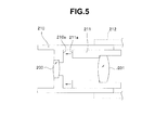
Fig. 5 is often provided to dispose an image pickup device package at the rear of the lens holding structure. - In the lens holding structure illustrated in
Fig. 5 , afirst lens frame 210 holding onelens 200 included in an objective lens group is joined to asecond lens frame 211 holding theother lens 201 by making thesecond lens frame 211 butt an inner portion of thefirst lens frame 210, whereby thelenses image pickup frame 212 holding a non-illustrated image pickup device package is joined to thesecond lens frame 211. - However, in the lens holding structure illustrated in
Fig. 5 , it is necessary to provide a fitting structure in which thefirst lens frame 210 and thesecond lens frame 211 are fitted to each other, in order to eliminate optical misalignment between thelens 200 and thelens 201 in a diameter direction. Therefore, when assembling is performed by inserting thesecond lens frame 211 into thefirst lens frame 210, the insertion resistance due to friction is large, which possibly causes not only deterioration of workability but also a failure due to an excessive load imposed on the lens. - In addition, when the
second lens frame 211 is fitted to thefirst lens frame 210, it is hard to check whether or not adistal end surface 211 a of thelens frame 211 surely abuts anabutting surface 210a of thefirst lens frame 210, and a gap is generated between theabutting surface 210a of thefirst lens frame 210 and thedistal end surface 211 a of thesecond lens frame 211, which causes variations in the positions in the optical axis direction of the lenses. As a result, there is a possibility that stable optical performance cannot be obtained. - Further, after the
first lens frame 210 and thesecond lens frame 211 are assembled, when an image pickup device package is held by joining theimage pickup frame 212 to thesecond lens frame 211, an excessive stress due to thermal expansion of resin acts on the cover glass on the image pickup surface side of the solid image pickup device depending on the amount of the resin which seals the circuit substrate and the electronic components of the image pickup device package, which possibly causes a failure. - The present invention has been achieved in view of the above-described circumstances, and an object of the present invention is to provide an image pickup apparatus capable of being surely fixed without applying excessive load to constituent elements and obtaining stable optical performance.
- An image pickup apparatus according to an aspect of the present invention provides an image pickup apparatus including an image pickup system disposed at a rear of an objective optical system, wherein the objective optical system includes a plurality of lenses and a plurality of lens frames, and in at least two lens frames of the plurality of lens frames, a first lens frame includes a step portion inside, which a distal end portion of a second lens frame is brought into contact with, the second lens frame includes a fitting portion that fits in an inner diameter of the first lens frame, and a contact portion that provides a gap between the inner diameter of the first lens frame and the contact portion, the contact portion being brought into contact with the step portion.
- An image pickup apparatus according to another aspect of the present invention provides an image pickup apparatus including an image pickup system disposed at a rear of an objective optical system, wherein the objective optical system includes a plurality of lenses and a plurality of lens frames, and in a configuration of at least two lens frames of the plurality of lens frames, a first lens frame includes a step portion and a slide portion inside, the step portion allowing a distal end portion of a second lens frame to be brought into contact therewith and the slide portion having a moving lens frame disposed thereon, which advances and retracts in an optical axis direction, on a front side of the step portion, the second lens frame includes a fitting portion that fits in an inner diameter of the first lens frame and a contact portion that provides a gap between the inner diameter of the first lens frame and the contact portion and is brought into contact with the step portion.
- An image pickup apparatus according to still another aspect of the present invention provides an image pickup apparatus including an image pickup system disposed at a rear of an objective optical system, wherein the image pickup system includes: a solid image pickup device that photoelectrically converts light incident from the objective optical system; a cover glass that covers an image pickup surface of the solid image pickup device; a circuit substrate portion disposed on a rear face opposite to the image pickup surface of the solid image pickup device; an inner lead extended from the circuit substrate portion, the inner lead being connected to a connection portion provided at a position which is on a side of the image pickup surface of the solid image pickup device and which is not covered by the cover glass; and a sealing resin provided on a side of the cover glass, the sealing resin not covering whole region of a side surface of the cover glass but covering up to an upper face of the inner lead.
-
-
Fig. 1 relates to a first embodiment of the present invention and is a configuration diagram illustrating an image pickup apparatus provided at a distal end of an insertion portion of an endoscope; -
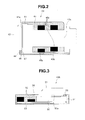
Fig. 2 relates to the first embodiment and is a diagram illustrating a configuration of an image pickup device package; -
Fig. 3 relates to the first embodiment and is a diagram illustrating a configuration of another image pickup device package; -
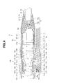
Fig. 4 relates to a second embodiment of the present invention and is a configuration diagram illustrating an image pickup apparatus provided at a distal end of an insertion portion of an endoscope; and -
Fig. 5 is a diagram illustrating a conventional lens holding structure. - A first embodiment of the present invention will be described below with reference to
Figs. 1 to 3 . - An image pickup apparatus according to the present invention is one employed in, for example, an endoscope including an image pickup device incorporated on the distal end side of an elongated insertion portion, which is inserted into a cavity in a site to be observed. As illustrated in
Fig. 1 , such image pickup apparatus 1 includes an objectiveoptical system unit 2, and an imagepickup system unit 30 arranged at the rear of the objectiveoptical system unit 2. - The objective
optical system unit 2 holds anobjective lens group 20, which includes a plurality of lenses, via afirst lens frame 3 and asecond lens frame 10 joined to thefirst lens frame 3. In the present embodiment, from among theobjective lens group 20, afirst lens 21 on the distal end side is held by thefirst lens frame 3 and a group of remaining lenses is held by thesecond lens frame 10. Furthermore, the respective lenses in theobjective lens group 20 are disposed at sites of the respective lens frames where perpendicularity and coaxiality are provided by means of high-precision processing. With such structure, the respective lenses in theobjective lens group 20 are disposed in the respective lens frames without inclination. - The
first lens frame 3 is formed in a substantially-cylindrical shape, and at a position close to a distal end in an inner portion of the cylindrical shape, aflange portion 4 that allows an outer circumferential portion on the proximal end side of thefirst lens 21 to be brought into contact therewith is provided. On the rear side of theflange portion 4, a space portion in which asecond lens frame 10 is received is provided. Note that if thefirst lens frame 3 is employed in, for example, an endoscope, thefirst lens frame 3 is fitted in a distal end frame of the endoscope, which is not illustrated, and held by a distal end portion of the endoscope. Furthermore, the outer circumferential portion of thefirst lens 21 held by thefirst lens frame 3 is joined in an air-tight manner to thefirst lens frame 3 by means of soldering or brazing, for example, taking autoclave sterilization processing into account. - Furthermore, the
second lens frame 10 holds the group of remaining lenses other than thefirst lens 21 in theobjective lens group 20, and thus holds asecond lens 22, adiaphragm 23, athird lens 24, a fourth lens 25 and a fifth lens 26 disposed at the rear of thefirst lens 21 in this order from the distal end side. Thesecond lens frame 10 holding such group of lenses is inserted into the space portion provided on the rear side of theflange portion 4 of thefirst lens frame 3, and a distal end portion of thesecond lens frame 10 is brought into contact with anend face 4a on the rear side of theflange portion 4 of thefirst lens frame 3, and a rear end portion of thesecond lens frame 10 is fitted on an inner wall surface of the space portion of thefirst lens frame 3 and fixed via, e.g., an adhesive. - More specifically, an outer shape of the
second lens frame 10 is formed to be a stepped cylindrical shape in which the distal end side and the rear end side have different outer diameters, and thesecond lens frame 10 includes acontact portion 11 having a cylindrical shape with a diameter smaller than that of an inner diameter of the space portion of thefirst lens frame 3, a distal end portion of thecontact portion 11 being brought into contact with theend face 4a on the rear side of theflange portion 4 of thefirst lens frame 3, and a cylindrically-shaped fitting portion 12 provided over a predetermined length on the rear end side of thecontact portion 11, thefitting portion 12 having a diameter larger than that of thecontact portion 11 and being fitted on the inner wall surface of the space portion of thefirst lens frame 3. In other words, thesecond lens frame 10 is formed so as to have a shape that forms agap 5 between the inner wall surface of the space portion of thefirst lens frame 3 and thesecond lens frame 10 when thesecond lens frame 10 is inserted into the space portion of thefirst lens frame 3. Also, a surface of the distal end portion of thesecond lens frame 10 and theend face 4a of theflange portion 4 of thefirst lens frame 3 are processed so as to have highly-precise perpendicularity to the optical axis. Furthermore, thefitting portion 12 is processed so as to have highly-precise coaxiality relative to the optical axis. - As a result of provision of
such gap 5, when thesecond lens frame 10 is inserted and fitted in thefirst lens frame 3, the area of contact between thefirst lens frame 3 and thesecond lens frame 10 is reduced and the insertion resistance is thereby reduced, enabling enhancement in assembling workability. In addition, the distal end portion of thesecond lens frame 10 can reliably be brought into contact with theend face 4a of theflange portion 4 of thefirst lens frame 3, whereby variations in coaxiality and/or perpendicularity and/or position in the optical axis direction between thefirst lens 21 disposed in thefirst lens frame 3 and the group of remaining lenses disposed inside thesecond lens frame 10 are eliminated, enabling prevention of optical performance deterioration. - Also, in order to provide optical precision, it is only necessary that only the rear end portion is fitted, and thus, the length of the fitting portion that requires a precise dimensional tolerance can be reduced, and if there is difficulty in processing the frame, employment of the present structure provides a cost reduction effect. Furthermore, when the
second lens frame 10 is fitted into thefirst lens frame 3, no undue load is imposed on the lens-attached portions, and thus, optical position deviations due to displacement of the lens-attached portions can be prevented, ensuring that worst situations such as lens breakage is avoided. - Furthermore, when an adhesive is applied to the
fitting portion 12 of thesecond lens frame 10 and thefitting portion 12 is assembled into thefirst lens frame 3, even if the adhesive applied on thefitting portion 12 flows toward the distal end side, the adhesive can be confined inside thegap 5, and does not flow between theend face 4a of theflange portion 4 of thefirst lens frame 3 and a distal end of thecontact portion 11 of thesecond lens frame 10. Accordingly, no misalignment in the optical axis direction among the lenses by the amount of a thickness of the layer of the flowed-in adhesive resulting from the adhesive flowing to the contact surface occurs, ensuring provision of a stable optical precision. - The above-described objective
optical system unit 2 is joined to the imagepickup system unit 30, and incoming light entering via theobjective lens group 20 forms an image on a light-receiving surface of a solidimage pickup device 41 inside the imagepickup system unit 30. Then, the optical image of a subject/object is subjected to photoelectric conversion by the solidimage pickup device 41, and an image pickup signal resulting from the photoelectric conversion is transmitted to a following signal processing circuit via asignal cable 70. - The objective
optical system unit 2 and the imagepickup system unit 30 are joined to each other by inserting and fitting thefirst lens frame 3 with thesecond lens frame 10 received and fixed thereto into an inner diameter portion of animage pickup frame 31 holding the imagepickup device package 40 and joining these two members to each other in an air-tight manner. The imagepickup device package 40 is one resulting from unitization by means of integral molding using aninsulating sealing resin 44. The integral molding is performed after acover glass 42 for protection is fixed to animage pickup surface 41 a of the solidimage pickup device 41 that includes, e.g., a CMOS or a CCD by means of adhesion using, e.g., an ultraviolet cure adhesive, acircuit substrate portion 43 with a plurality of electronic components such as capacitors, resistances and/or transistors mounted thereon is disposed on the rear side of the solid image pickup device 41 (the back side of theimage pickup surface 41a), and the solidimage pickup device 41 and thecircuit substrate portion 43 are electrically connected. - In the present embodiment, as illustrated in
Fig. 2 , the imagepickup device package 40 includes amultilayer substrate 43a with a plurality ofelectronic components 45a mounted in a recess portion formed inside, and aflexible substrate 43b with a plurality ofelectronic components 45b mounted thereon as thecircuit substrate portion 43 disposed on the rear side of the solidimage pickup device 41. Themultilayer substrate 43a and theflexible substrate 43b are electrically connected by means of, for example, bump connection, and furthermore, aninner lead 46 extending from theflexible substrate 43b is connected to abonding portion 47 provided at a site on theimage pickup surface 41 a side of the solidimage pickup device 41, the site being not covered by thecover glass 42. - Such image
pickup device package 40 is formed by integral molding performed in such a manner that thesubstrates electronic components sealing resin 44 and thesealing resin 44 covers up to an upper face of theinner lead 46 connected to thebonding portion 47 of the solidimage pickup device 41, and an entire side of thecover glass 42 is not covered by the sealing resin. In other words, an upper face portion of theinner lead 46 disposed on a surface of the solidimage pickup device 41 that is not covered by thecover glass 42 is sealed by a minimum amount of resin that can protect the relevant electronic equipment part, and thus, even if thesealing resin 44 thermally expands because of temperature change, no undue load is imposed on thecover glass 42 and/or the portion of connection between theinner lead 46 and thebonding portion 47. Accordingly, cracking of thecover glass 42 and/or a failure in connection in the portion of connection between theinner lead 46 and thebonding portion 47 in the imagepickup device package 40 due to stress caused by, e.g., transportation before assembly of theimage pickup unit 30 can be avoided. Note that on the rear end side of themultilayer substrate 43 a, a portion of connection with thesignal cable 70 is provided, and the portion of connection is exposed without being covered by thesealing resin 44. - In the image
pickup device package 40 formed by integral molding using thesealing resin 44, acover glass 32 for centering, which is fixed on the inner diameter side of theimage pickup frame 31 so as to face the fifth lens 26, is adhered and joined to thecover glass 42 via, e.g., a translucent optical adhesive. In other words, the imagepickup device package 40 is held to theimage pickup frame 31 via thecover glass 32 for centering. Furthermore, with thesignal cable 70 connected to the imagepickup device package 40, ashield frame 33 is fitted on an outer circumference on the rear end side of theimage pickup frame 31, and the imagepickup device package 40 is fixed by an adhesive 60 including, e.g., a thermoset resin charged between theimage pickup frame 31 and the imagepickup device package 40 and between theshield frame 33, and imagepickup device package 40 and the portion of connection with thesignal cable 70. Note that a range from an outer circumference of theshield frame 33 to the distal end side of thesignal cable 70 is covered by aprotection tube 34 including, e.g., a heat-shrinkable tube. - The above-described image
pickup device package 40 is one contemplated for use in a front-view endoscope for observation in a direction along a direction of insertion of the endoscope. However, a configuration similar to the above can be employed in a side-view endoscope for observation in a direction substantially perpendicular to the insertion direction. - For example, an image
pickup device package 40A, which is illustrated inFig. 3 , is one in which animage pickup surface 50a of a solidimage pickup device 50 is directed in a direction perpendicular to an optical axis direction of an objective optical system and, e.g., a non-illustrated prism is disposed on an upper face of acover glass 51. In the imagepickup device package 40A, on the lower side of the solid image pickup device 50 (the back side of theimage pickup surface 50a), aflexible substrate 53 with a plurality ofelectronic components 52 mounted thereon is arranged and aninner lead 54 extending from theflexible substrate 53 is connected to abonding portion 55 provided on a site of theimage pickup surface 50a of the solidimage pickup device 50 that is not covered by thecover glass 51. Then, integral molding is performed using an insulating sealingresin 56 so that theelectronic components 52 and theflexible substrate 53 are sealed by the sealingresin 56 and the sealingresin 56 covers up to an upper face of theinner lead 54 connected to thebonding portion 55, thereby forming the imagepickup device package 40A. - Next, a fixing structure for the
signal cable 70 connected to the imagepickup device package 40 will be described. Referring back toFig. 1 , thesignal cable 70 is fixed together with the imagepickup device package 40 via the adhesive 60 with a plurality ofelectric wires 70b exposed from anouter covering 70a in the vicinity of an end portion of theshield frame 33 fitted on theimage pickup frame 31 and with theelectric wires 70b connected to the imagepickup device package 40 via, for example, soldering. - Here, a part around a strip end of the
outer covering 70a from which theelectric wires 70b are exposed is fixed by acable fixing thread 71, and further covered by anelastic tube 72 having a predetermined length. The distal end side of theelastic tube 72 is fixed by anothercable fixing thread 73 at a position that is somewhat on the rear side relative to thecable fixing thread 71, and a rear end of theelastic tube 72 is provided so as to extend up to the rear of a bending portion of the endoscope. Furthermore, the distal end side of theelastic tube 72 is covered by a heat-shrinkable tube 74. The part around the strip end of thesignal cable 70 doubly covered by theelastic tube 72 and the heat-shrinkable tube 74 is finally fixed by an adhesive 75 charged in addition to the adhesive 60 for fixing the imagepickup device package 40 and theelectric wires 70b inside theprotection tube 34 covering theshield frame 33. Also, a rear end of the heat-shrinkable tube 74 is disposed at a position that is on the rear side relative to a rear end of theprotection tube 34, and is on the front side relative to a joint portion between a rigid portion, which is not bent, on the distal end side of the insertion portion of the endoscope and a bending portion, which includes a plurality of bending pieces. In addition, the heat-shrinkable tube 74 includes an elastic material. - In such fixing structure for the
signal cable 70, theelastic tube 72 and the heat-shrinkable tube 74, which each hold thesignal cable 70 with a gap between theouter covering 70a and theelastic tube 72 or the heat-shrinkable tube 74, exist at the rear of a portion rigidly fixed by the adhesive 60, which results in provision of a part whose hardness gently changes from the rigid part to a flexible part of the cable itself. Accordingly, even if an outer force in a bending direction is acted on thesignal cable 70, thesignal cable 70 is gently curved without partial concentration of stress, enabling prevention of disconnection of the inner electric wires. - Next, a second embodiment of the present invention will be described with reference to
Fig. 4 . - In
Fig. 4 , animage pickup apparatus 1A includes an objectiveoptical system unit 100, and an imagepickup system unit 30 that is arranged at the rear of the objectiveoptical system unit 100 and is similar to that of the first embodiment. - The above-described objective
optical system unit 100 is joined to the imagepickup system unit 30, and an incoming light entering via an objective lens group forms an image on a light-receiving surface of a solidimage pickup device 41 inside the imagepickup system unit 30. Then, the optical image of a subject/object is subjected to photoelectric conversion by the solidimage pickup device 41, and an image pickup signal resulting from the photoelectric conversion is transmitted to a following signal processing circuit via a signal cable. - The objective
optical system unit 100 includes afirst lens frame 101 holding a first lens group, a moving lens frame 110 holding a moving lens group, asecond lens frame 104 holding remaining lens groups, athird lens frame 113 receiving the moving lens frame 110 and holding thesecond lens frame 104, a fourth lens frame 114 holding thefirst lens frame 101 and thethird lens frame 113, and an adjustment ring 116 that fits on an outer shape of thethird lens frame 113. - The
third lens frame 113 receives the moving lens frame 110, and holds asecond lens frame 104. Thethird lens frame 113 is formed so as to have a substantially-cylindrical shape, and an inner surface of the cylindrical shape portion serves as a slide surface on which the moving lens frame 110 advances and retracts. Furthermore, in the cylindrical shape portion, a slit for disposition of an action portion 110a of the moving lens frame 110 that is advanced and retracted by an actuator 28. Furthermore, respective lenses in the first lens group, the second lens group and the moving lens group are disposed at sites in the respective lens frames where perpendicularity and coaxiality are provided by means of high-precision processing. With such structure, the respective lenses in the first lens group, the second lens group and the moving lens group are disposed in the respective lens frames without inclination. - Also, on the inner surface of the cylindrical shape, a step portion 113a is provided. On the rear side of the step portion 113a, a space portion that receives the
second lens frame 104 is provided. Also, on an outer surface of the cylindrical shape portion, a projection portion 113b for disposing an actuator 28 is provided. - The fourth lens frame 114 is formed so as to have a substantially-cylindrical shape, and holds the
first lens frame 101 and thethird lens frame 113. On an outer surface of the cylindrical shape, aprojection portion 114a is provided. In theprojection portion 114a, arecess portion 114b that receives a spring 115 brought into contact with the action portion 110a of the moving lens frame 110 is provided. - Note that if the
first lens frame 101 is employed in, for example, an endoscope, thefirst lens frame 101 is fitted in a distal end frame of the endoscope, which is not illustrated, and held by a distal end portion of the endoscope. - The
first lens frame 101 is formed in a substantially-cylindrical shape, and at a position close to a distal end in an inner portion of the cylindrical shape, aflange portion 101a, which an outer circumferential portion on the proximal end side of thefirst lens 103 is brought into contact with via afirst diaphragm 102 is provided. On the rear side of theflange portion 101a, acontact portion 101b brought into contact with the fourth lens frame 114 and a projection portion that fits in the fourth lens frame 114 are provided. - Note that if the
first lens frame 101 is employed in, for example, an endoscope, thefirst lens frame 101 is brought into contact with a distal end frame of the endoscope, which is not illustrated, in an optical axis direction, whereby positioning of the image pickup apparatus relative to the distal end frame of the endoscope is determined. - The
second lens frame 104 holds the remaining lens groups of the objective lens group other than the first lens group and the moving lens group, and holds athird diaphragm 106, athird lens 105, a cementedlens 107, aspacer 108 and afirst filter 109 disposed at the rear of the moving lens group in this order from the distal end side. Thesecond lens frame 104 holding these lens groups is inserted into the space portion provided on the rear side of the step portion of thethird lens frame 113, an intermediate portion of thesecond lens frame 104 is brought into contact with an end face on the rear side of the step portion of thesecond lens frame 104, and a rear end portion of thesecond lens frame 104 is fitted on an inner wall surface of the space portion of thethird lens frame 113 and fixed via, e.g., an adhesive. - The
second lens frame 104 is formed in a stepped substantially-cylindrical shape in which a distalend projection portion 104a, theintermediate portion 104b and arear end portion 104c have different outer diameters in the outer shape, and thesecond lens frame 104 includes acontact portion 104d via which theintermediate portion 104b having a cylindrical shape with a diameter smaller than an inner diameter of the space portion of thethird lens frame 113 is brought into contact with the end face on the rear side of the step portion of thethird lens frame 113, and a cylindrically-shaped fitting portion 104e provided over a predetermined length on the rear end side of thecontact portion 104d, the fitting portion 104e having a diameter larger than that of thecontact portion 104d and being fitted on the inner wall surface of the space portion of thethird lens frame 113. In other words, thesecond lens frame 104 is formed in a shape that forms a gap A between the inner wall surface of the space portion of thethird lens frame 113 and thesecond lens frame 104 when thesecond lens frame 104 is inserted into the space portion of thethird lens frame 113. Furthermore, a surface of a distal end portion of thesecond lens frame 104 and the end face on the rear side of the step portion of thethird lens frame 113 are processed so as to have highly-precise perpendicularity to the optical axis. Furthermore, the fitting portion 104e is processed so as to have highly-precise coaxiality relative to the optical axis. - As a result of provision of such gap, when the
second lens frame 104 is inserted and fitted in thethird lens frame 113, the area of contact between thethird lens frame 113 and thesecond lens frame 104 is reduced and the insertion resistance is thereby reduced, enabling enhancement in assembling workability. In addition, theintermediate portion 104b of thesecond lens frame 104 can reliably be brought into contact with an end face of the step portion 113a of thethird lens frame 113, whereby variations in position in the optical axis direction are eliminated, enabling provision of a stable optical precision, and thus, variations in coaxiality and/or perpendicularity and/or position in optical axis direction between thefirst lens 103 disposed in thefirst lens frame 101 and the remaining lens groups disposed inside thesecond lens frame 104 are eliminated, enabling prevention of optical performance deterioration. - Also, in order to provide optical precision, it is only necessary that only the rear end portion is fitted, and thus, the length of the fitting portion that requires a precise dimensional tolerance can be reduced, and if there is difficulty in processing the frame, employment of the present structure provides a cost reduction effect. Furthermore, when an adhesive is applied to the fitting portion 104e of the
second lens frame 104 and the fitting portion 104e is assembled into thethird lens frame 113, even if the adhesive applied on the fitting portion 104e flows toward the distal end side, the adhesive can be confined inside the gap A, and does not flow between the end face of the step portion 113a of thethird lens frame 113 and the distal end of thecontact portion 104d of thesecond lens frame 104. Accordingly, no misalignment in the optical axis direction among the lenses by the amount of a thickness of the layer of the flowed-in adhesive resulting from the adhesive flowing to the contact surface occurs, ensuring provision of a stable optical precision. - Furthermore, a length from the
contact portion 104d of thesecond lens frame 104 to the rear end of thethird lens frame 113 is made to be longer than a length from the step portion 113a of thethird lens frame 113 to a rear end of thethird lens frame 113, thereby providing an assemblingportion 104f. - As a result of provision of
such assembling portion 104f and the gap A, the assemblingportion 104f is pushed when thesecond lens frame 104 is fitted in thethird lens frame 113 and thus, no undue load is imposed on thefirst filter 109 and/or the cementedlens 107 via thefirst filter 109 and thespacer 108, ensuring that worst situations such as breakage of thefirst filter 109 and/or the cementedlens 107 are avoided. - Furthermore, the
second lens frame 104 includes a distalend projection portion 104a holding thethird lens 105 disposed so as to project in the moving lens frame 110 on the front side relative to the step portion of thethird lens frame 113 and having a diameter smaller than an inner diameter of moving lens frame 110. - Provision of such distal
end projection portion 104a enables the slide surface of thethird lens frame 113 to have a long length in the optical axis direction, and since a slide stroke from a WIDE position to a TELE position of the moving lens frame 110 is set according to an optical design, enabling the slide surface of the moving lens frame 110 to have a long length in the optical axis direction. Consequently, when the moving lens frame 110 is advanced and retracted by an operation of the actuator 28, inclination of the moving lens frame 110 relative to the diameter direction of thethird lens frame 113 can be suppressed, enabling provision of stable optical performance and smooth advancing and retracting operation of the moving lens frame 110. - The moving lens frame 110 holds a
second diaphragm 112 and a movinglens 111. The moving lens frame 110 is formed in a cylindrical shape, and an outer surface of the cylindrical shape portion serves as a slide surface that slides on thethird lens frame 113, and furthermore, on the outer surface of the cylindrical shape portion, a projection-shaped action portion 110a on which a force from the actuator 28 acts is provided. - Next, a fixing structure for a
signal cable 70 connected to the imagepickup device package 40 will be described. As in the first embodiment illustrated inFig. 1 , thesignal cable 70 is fixed together with an imagepickup device package 40 via an adhesive 60 with a plurality ofelectric wires 70b exposed from anouter covering 70a in the vicinity of an end portion of ashield frame 33 fitted on animage pickup frame 31 and with theelectric wires 70b connected to the imagepickup device package 40 via, for example, soldering. - Here, a part around a strip end of the
outer covering 70a from which theelectric wires 70b are exposed is fixed by acable fixing thread 71, and further covered by anelastic tube 72 having a predetermined length. The distal end side of theelastic tube 72 is fixed by anothercable fixing thread 73 at a position that is somewhat on the rear side relative to thecable fixing thread 71, and a rear end of theelastic tube 72 is provided so as to extend up to the rear of a bending portion of the endoscope. Furthermore, the distal end side of theelastic tube 72 is covered by a heat-shrinkable tube 74. The part around the strip end of thesignal cable 70 doubly covered by theelastic tube 72 and the heat-shrinkable tube 74 is finally fixed by an adhesive 75 charged in addition to the adhesive 60 for fixing the imagepickup device package 40 and theelectric wires 70b inside theprotection tube 34 covering theshield frame 33. Also, a rear end of the heat-shrinkable tube 74 is disposed at a position that is on the rear side relative to a rear end of theprotection tube 34 and is on the front side relative to a joint portion between a rigid portion, which is not bent, on the distal end side of an insertion portion of the endoscope and a bending portion, which includes a plurality of bending pieces. In addition, the heat-shrinkable tube 74 includes an elastic material. - In such fixing structure for the
signal cable 70, theelastic tube 72 and the heat-shrinkable tube 74, which each hold thesignal cable 70 with a gap between theouter covering 70a and theelastic tube 72 or the heat-shrinkable tube 74, exist at the rear of a portion rigidly fixed by the adhesive 60, which results in provision of a part whose hardness gently changes from the rigid part to a flexible part of the cable itself. Accordingly, even if an outer force in a bending direction is acted on thesignal cable 70, thesignal cable 70 is gently curved without partial concentration of stress, enabling prevention of disconnection of the inner electric wires. - As in the above-described first embodiment, the objective
optical system unit 100 and the imagepickup system unit 30 are joined to each other by inserting and fitting thethird lens frame 113 with thesecond lens frame 104 received and fixed thereto into an inner diameter portion of theimage pickup frame 31 holding the imagepickup device package 40 and joining these two members to each other in an air-tight manner. The imagepickup device package 40 is one resulting from unitization by means of integral molding as in the above-described first embodiment. - The image
pickup device package 40 in the present embodiment also employs a configuration similar to that illustrated inFig. 2 as in the above-described first embodiment. - The present application is filed claiming the priority of Japanese Patent Application No.
2011-083849
Claims (9)
- An image pickup apparatus including an image pickup system disposed at a rear of an objective optical system,
wherein the objective optical system includes a plurality of lenses and a plurality of lens frames, and in at least two lens frames of the plurality of lens frames,
a first lens frame includes a step portion inside, which a distal end portion of a second lens frame is brought into contact with,
the second lens frame includes a fitting portion that fits in an inner diameter of the first lens frame, and a contact portion that provides a gap between the inner diameter of the first lens frame and the contact portion, the contact portion being brought into contact with the step portion. - An image pickup apparatus including an image pickup system disposed at a rear of an objective optical system,
wherein the objective optical system includes a plurality of lenses and a plurality of lens frames, and in a configuration of at least two lens frames of the plurality of lens frames,
a first lens frame includes a step portion and a slide portion inside, the step portion allowing a distal end portion of a second lens frame to be brought into contact therewith and the slide portion having a moving lens frame disposed thereon, which advances and retracts in an optical axis direction, on a front side of the step portion,
the second lens frame includes a fitting portion that fits in an inner diameter of the first lens frame and a contact portion that provides a gap between the inner diameter of the first lens frame and the contact portion and is brought into contact with the step portion. - The image pickup apparatus according to claim 2, wherein the second lens frame includes a projection portion having at least one lens disposed therein, on the front side relative to the step portion, and the projection portion projects inside the moving lens frame.
- The image pickup apparatus according to claim 2 or 3, wherein the first lens frame includes a slit formed for disposition of an action portion that is acted upon by an actuator that advances and retracts the moving lens frame.
- The image pickup apparatus according to any one of claims 1 to 4, wherein a rear end of the second lens frame projects toward a rear side relative to a rear end of the first lens frame.
- An image pickup apparatus including an image pickup system disposed at a rear of an objective optical system,
wherein the image pickup system includes:a solid image pickup device that photoelectrically converts light incident from the objective optical system;a cover glass that covers an image pickup surface of the solid image pickup device;a circuit substrate portion disposed on a rear face opposite to the image pickup surface of the solid image pickup device;an inner lead extended from the circuit substrate portion, the inner lead being connected to a connection portion provided at a position which is on a side of the image pickup surface of the solid image pickup device and which is not covered by the cover glass; anda sealing resin provided on a side of the cover glass, the sealing resin not covering whole region of a side surface of the cover glass but covering up to an upper face of the inner lead. - The image pickup apparatus according to claim 6, wherein the circuit substrate portion includes a flexible substrate connected to the solid image pickup device via the inner lead, a circuit substrate connected to the flexible substrate, and a plurality of electronic components mounted on the respective substrates.
- The image pickup apparatus according to claim 6 or 7, wherein the sealing resin is formed so as to integrally cover from the inner lead to the circuit substrate portion.
- The image pickup apparatus according to any one of claims 6 to 8, wherein the circuit substrate portion includes a recess portion formed inside thereof.
Applications Claiming Priority (2)
| Application Number | Priority Date | Filing Date | Title |
|---|---|---|---|
| JP2011083849 | 2011-04-05 | ||
| PCT/JP2012/058970 WO2012137739A1 (en) | 2011-04-05 | 2012-04-02 | Imaging apparatus |
Publications (3)
| Publication Number | Publication Date |
|---|---|
| EP2605053A1 true EP2605053A1 (en) | 2013-06-19 |
| EP2605053A4 EP2605053A4 (en) | 2015-04-29 |
| EP2605053B1 EP2605053B1 (en) | 2016-06-01 |
Family
ID=46969137
Family Applications (1)
| Application Number | Title | Priority Date | Filing Date |
|---|---|---|---|
| EP12767236.8A Not-in-force EP2605053B1 (en) | 2011-04-05 | 2012-04-02 | Image pickup apparatus |
Country Status (5)
| Country | Link |
|---|---|
| US (1) | US8823787B2 (en) |
| EP (1) | EP2605053B1 (en) |
| JP (1) | JP5167437B2 (en) |
| CN (1) | CN103069323B (en) |
| WO (1) | WO2012137739A1 (en) |
Cited By (2)
| Publication number | Priority date | Publication date | Assignee | Title |
|---|---|---|---|---|
| US10962763B2 (en) | 2017-05-26 | 2021-03-30 | Olympus Corporation | Optical unit |
| US12078794B2 (en) | 2018-06-05 | 2024-09-03 | Olympus Corporation | Endoscope |
Families Citing this family (20)
| Publication number | Priority date | Publication date | Assignee | Title |
|---|---|---|---|---|
| JP6125796B2 (en) * | 2012-10-30 | 2017-05-10 | 日本電産サンキョー株式会社 | Wide-angle lens and wide-angle lens unit |
| CN105338883A (en) * | 2013-03-15 | 2016-02-17 | 奥利弗医疗公司 | Mechanical image rotation for rigidly coupled image sensor and endoscope |
| WO2015083490A1 (en) * | 2013-12-03 | 2015-06-11 | オリンパス株式会社 | Optical unit for endoscope |
| DE102014208652A1 (en) * | 2014-05-08 | 2015-11-12 | Olympus Winter & Ibe Gmbh | Videoscope |
| CN106455922B (en) * | 2014-05-15 | 2018-03-27 | 奥林巴斯株式会社 | Optical unit and the endoscope with the optical unit |
| JP5914784B2 (en) * | 2014-05-16 | 2016-05-11 | オリンパス株式会社 | Endoscopic imaging apparatus and method for assembling endoscopic imaging apparatus |
| JP6456064B2 (en) * | 2014-07-15 | 2019-01-23 | オリンパス株式会社 | Lens fixing device, method for adjusting lens fixing device, and lens fixing method |
| DE112014006987B4 (en) | 2014-12-18 | 2018-12-20 | Olympus Corporation | Optical unit and endoscope |
| WO2017038149A1 (en) * | 2015-09-01 | 2017-03-09 | オリンパス株式会社 | Observation optical system unit, imaging unit, and endoscope |
| WO2017199776A1 (en) * | 2016-05-19 | 2017-11-23 | オリンパス株式会社 | Imaging unit and endoscope |
| JP6230771B1 (en) * | 2016-06-17 | 2017-11-15 | オリンパス株式会社 | Endoscope device |
| WO2018013204A1 (en) | 2016-07-14 | 2018-01-18 | Intuitive Surgical Operations, Inc. | An endoscope including a plurality of individually testable subassemblies |
| KR102657753B1 (en) | 2016-07-14 | 2024-04-17 | 인튜어티브 서지컬 오퍼레이션즈 인코포레이티드 | A pressure test port contained within a body of surgical instrument |
| KR101889914B1 (en) * | 2016-12-06 | 2018-08-21 | 해성옵틱스(주) | Micro endoscope camera module and micro endoscope having the same |
| WO2018186207A1 (en) * | 2017-04-06 | 2018-10-11 | オリンパス株式会社 | Imaging unit and endoscope |
| DE102017127827B4 (en) * | 2017-11-24 | 2022-01-05 | Karl Storz Se & Co. Kg | Optical instrument |
| JP7011220B2 (en) * | 2018-02-02 | 2022-02-10 | コニカミノルタ株式会社 | Optical unit |
| WO2019163175A1 (en) | 2018-02-20 | 2019-08-29 | オリンパス株式会社 | Image pickup unit and endoscope |
| WO2021152673A1 (en) * | 2020-01-27 | 2021-08-05 | オリンパス株式会社 | Endoscope tip structure and method for manufacturing endoscope tip structure |
| WO2022190244A1 (en) * | 2021-03-10 | 2022-09-15 | オリンパス株式会社 | Endoscope imaging unit and endoscope |
Family Cites Families (8)
| Publication number | Priority date | Publication date | Assignee | Title |
|---|---|---|---|---|
| US5661609A (en) * | 1993-07-06 | 1997-08-26 | Olympus Optical Co., Ltd. | Lens mount |
| JP3456785B2 (en) * | 1995-03-03 | 2003-10-14 | 富士写真光機株式会社 | Camera lens barrel |
| JPH09281375A (en) * | 1996-04-17 | 1997-10-31 | Olympus Optical Co Ltd | Lens barrel |
| JP2002090603A (en) * | 2000-07-10 | 2002-03-27 | Matsushita Electric Ind Co Ltd | Waterproof camera |
| JP4589659B2 (en) * | 2004-05-31 | 2010-12-01 | Hoya株式会社 | Method for assembling the tip of the electronic endoscope |
| JP4795202B2 (en) * | 2006-11-07 | 2011-10-19 | オリンパスメディカルシステムズ株式会社 | Imaging device |
| JP2008307293A (en) | 2007-06-15 | 2008-12-25 | Olympus Medical Systems Corp | Imaging device |
| JP5393060B2 (en) * | 2008-06-04 | 2014-01-22 | オリンパスメディカルシステムズ株式会社 | Imaging unit |
-
2012
- 2012-04-02 WO PCT/JP2012/058970 patent/WO2012137739A1/en not_active Ceased
- 2012-04-02 EP EP12767236.8A patent/EP2605053B1/en not_active Not-in-force
- 2012-04-02 JP JP2012546278A patent/JP5167437B2/en active Active
- 2012-04-02 CN CN201280002340.7A patent/CN103069323B/en active Active
- 2012-10-05 US US13/646,058 patent/US8823787B2/en active Active
Non-Patent Citations (2)
| Title |
|---|
| No Search * |
| See also references of WO2012137739A1 * |
Cited By (2)
| Publication number | Priority date | Publication date | Assignee | Title |
|---|---|---|---|---|
| US10962763B2 (en) | 2017-05-26 | 2021-03-30 | Olympus Corporation | Optical unit |
| US12078794B2 (en) | 2018-06-05 | 2024-09-03 | Olympus Corporation | Endoscope |
Also Published As
| Publication number | Publication date |
|---|---|
| US20130027534A1 (en) | 2013-01-31 |
| US8823787B2 (en) | 2014-09-02 |
| WO2012137739A1 (en) | 2012-10-11 |
| JP5167437B2 (en) | 2013-03-21 |
| EP2605053B1 (en) | 2016-06-01 |
| EP2605053A4 (en) | 2015-04-29 |
| JPWO2012137739A1 (en) | 2014-07-28 |
| CN103069323A (en) | 2013-04-24 |
| CN103069323B (en) | 2015-05-20 |
Similar Documents
| Publication | Publication Date | Title |
|---|---|---|
| EP2605053B1 (en) | Image pickup apparatus | |
| EP2532296B1 (en) | Image pickup unit for endoscope | |
| JP5041925B2 (en) | Imaging unit | |
| US9784964B2 (en) | Image pickup unit for endoscope having multiple bonded frames | |
| JP5374669B1 (en) | Endoscope | |
| JP6057595B2 (en) | Endoscope | |
| WO2014156149A1 (en) | Endoscope and endoscope system | |
| CN105828689B (en) | Photographic device and endoscope apparatus | |
| JP5389376B2 (en) | Endoscope imaging unit | |
| JP5189209B2 (en) | Endoscope structure of endoscope | |
| JP2015047278A (en) | Endoscope | |
| JP2015073537A (en) | Endoscope and endoscope system | |
| JP7207892B2 (en) | LENS DEVICE AND IMAGING DEVICE INCLUDING THE SAME | |
| JP4253369B2 (en) | Electronic endoscope | |
| JPH0664249B2 (en) | Endoscope | |
| JP6574282B2 (en) | Imaging module and manufacturing method thereof | |
| JPS63119736A (en) | Endoscope | |
| JPH04114623A (en) | Camera for endoscope | |
| JPH0438417B2 (en) | ||
| CN106999010A (en) | Image unit and endoscope |
Legal Events
| Date | Code | Title | Description |
|---|---|---|---|
| PUAI | Public reference made under article 153(3) epc to a published international application that has entered the european phase |
Free format text: ORIGINAL CODE: 0009012 |
|
| 17P | Request for examination filed |
Effective date: 20130104 |
|
| AK | Designated contracting states |
Kind code of ref document: A1 Designated state(s): AL AT BE BG CH CY CZ DE DK EE ES FI FR GB GR HR HU IE IS IT LI LT LU LV MC MK MT NL NO PL PT RO RS SE SI SK SM TR |
|
| DAX | Request for extension of the european patent (deleted) | ||
| RA4 | Supplementary search report drawn up and despatched (corrected) |
Effective date: 20150327 |
|
| RIC1 | Information provided on ipc code assigned before grant |
Ipc: A61B 1/04 20060101ALI20150323BHEP Ipc: A61B 1/00 20060101ALI20150323BHEP Ipc: G02B 7/02 20060101AFI20150323BHEP Ipc: G02B 23/24 20060101ALI20150323BHEP |
|
| RAP1 | Party data changed (applicant data changed or rights of an application transferred) |
Owner name: OLYMPUS CORPORATION |
|
| GRAP | Despatch of communication of intention to grant a patent |
Free format text: ORIGINAL CODE: EPIDOSNIGR1 |
|
| INTG | Intention to grant announced |
Effective date: 20151202 |
|
| GRAS | Grant fee paid |
Free format text: ORIGINAL CODE: EPIDOSNIGR3 |
|
| GRAA | (expected) grant |
Free format text: ORIGINAL CODE: 0009210 |
|
| AK | Designated contracting states |
Kind code of ref document: B1 Designated state(s): AL AT BE BG CH CY CZ DE DK EE ES FI FR GB GR HR HU IE IS IT LI LT LU LV MC MK MT NL NO PL PT RO RS SE SI SK SM TR |
|
| REG | Reference to a national code |
Ref country code: GB Ref legal event code: FG4D |
|
| REG | Reference to a national code |
Ref country code: CH Ref legal event code: EP Ref country code: AT Ref legal event code: REF Ref document number: 804210 Country of ref document: AT Kind code of ref document: T Effective date: 20160615 |
|
| REG | Reference to a national code |
Ref country code: IE Ref legal event code: FG4D |
|
| REG | Reference to a national code |
Ref country code: DE Ref legal event code: R096 Ref document number: 602012019209 Country of ref document: DE |
|
| REG | Reference to a national code |
Ref country code: LT Ref legal event code: MG4D |
|
| RAP2 | Party data changed (patent owner data changed or rights of a patent transferred) |
Owner name: OLYMPUS CORPORATION |
|
| RAP2 | Party data changed (patent owner data changed or rights of a patent transferred) |
Owner name: OLYMPUS CORPORATION |
|
| REG | Reference to a national code |
Ref country code: NL Ref legal event code: MP Effective date: 20160601 |
|
| PG25 | Lapsed in a contracting state [announced via postgrant information from national office to epo] |
Ref country code: FI Free format text: LAPSE BECAUSE OF FAILURE TO SUBMIT A TRANSLATION OF THE DESCRIPTION OR TO PAY THE FEE WITHIN THE PRESCRIBED TIME-LIMIT Effective date: 20160601 Ref country code: NO Free format text: LAPSE BECAUSE OF FAILURE TO SUBMIT A TRANSLATION OF THE DESCRIPTION OR TO PAY THE FEE WITHIN THE PRESCRIBED TIME-LIMIT Effective date: 20160901 Ref country code: LT Free format text: LAPSE BECAUSE OF FAILURE TO SUBMIT A TRANSLATION OF THE DESCRIPTION OR TO PAY THE FEE WITHIN THE PRESCRIBED TIME-LIMIT Effective date: 20160601 |
|
| REG | Reference to a national code |
Ref country code: AT Ref legal event code: MK05 Ref document number: 804210 Country of ref document: AT Kind code of ref document: T Effective date: 20160601 |
|
| PG25 | Lapsed in a contracting state [announced via postgrant information from national office to epo] |
Ref country code: SE Free format text: LAPSE BECAUSE OF FAILURE TO SUBMIT A TRANSLATION OF THE DESCRIPTION OR TO PAY THE FEE WITHIN THE PRESCRIBED TIME-LIMIT Effective date: 20160601 Ref country code: RS Free format text: LAPSE BECAUSE OF FAILURE TO SUBMIT A TRANSLATION OF THE DESCRIPTION OR TO PAY THE FEE WITHIN THE PRESCRIBED TIME-LIMIT Effective date: 20160601 Ref country code: ES Free format text: LAPSE BECAUSE OF FAILURE TO SUBMIT A TRANSLATION OF THE DESCRIPTION OR TO PAY THE FEE WITHIN THE PRESCRIBED TIME-LIMIT Effective date: 20160601 Ref country code: GR Free format text: LAPSE BECAUSE OF FAILURE TO SUBMIT A TRANSLATION OF THE DESCRIPTION OR TO PAY THE FEE WITHIN THE PRESCRIBED TIME-LIMIT Effective date: 20160902 Ref country code: NL Free format text: LAPSE BECAUSE OF FAILURE TO SUBMIT A TRANSLATION OF THE DESCRIPTION OR TO PAY THE FEE WITHIN THE PRESCRIBED TIME-LIMIT Effective date: 20160601 Ref country code: HR Free format text: LAPSE BECAUSE OF FAILURE TO SUBMIT A TRANSLATION OF THE DESCRIPTION OR TO PAY THE FEE WITHIN THE PRESCRIBED TIME-LIMIT Effective date: 20160601 Ref country code: LV Free format text: LAPSE BECAUSE OF FAILURE TO SUBMIT A TRANSLATION OF THE DESCRIPTION OR TO PAY THE FEE WITHIN THE PRESCRIBED TIME-LIMIT Effective date: 20160601 |
|
| PG25 | Lapsed in a contracting state [announced via postgrant information from national office to epo] |
Ref country code: IT Free format text: LAPSE BECAUSE OF FAILURE TO SUBMIT A TRANSLATION OF THE DESCRIPTION OR TO PAY THE FEE WITHIN THE PRESCRIBED TIME-LIMIT Effective date: 20160601 Ref country code: IS Free format text: LAPSE BECAUSE OF FAILURE TO SUBMIT A TRANSLATION OF THE DESCRIPTION OR TO PAY THE FEE WITHIN THE PRESCRIBED TIME-LIMIT Effective date: 20161001 Ref country code: EE Free format text: LAPSE BECAUSE OF FAILURE TO SUBMIT A TRANSLATION OF THE DESCRIPTION OR TO PAY THE FEE WITHIN THE PRESCRIBED TIME-LIMIT Effective date: 20160601 Ref country code: CZ Free format text: LAPSE BECAUSE OF FAILURE TO SUBMIT A TRANSLATION OF THE DESCRIPTION OR TO PAY THE FEE WITHIN THE PRESCRIBED TIME-LIMIT Effective date: 20160601 Ref country code: RO Free format text: LAPSE BECAUSE OF FAILURE TO SUBMIT A TRANSLATION OF THE DESCRIPTION OR TO PAY THE FEE WITHIN THE PRESCRIBED TIME-LIMIT Effective date: 20160601 Ref country code: SK Free format text: LAPSE BECAUSE OF FAILURE TO SUBMIT A TRANSLATION OF THE DESCRIPTION OR TO PAY THE FEE WITHIN THE PRESCRIBED TIME-LIMIT Effective date: 20160601 |
|
| PG25 | Lapsed in a contracting state [announced via postgrant information from national office to epo] |
Ref country code: PT Free format text: LAPSE BECAUSE OF FAILURE TO SUBMIT A TRANSLATION OF THE DESCRIPTION OR TO PAY THE FEE WITHIN THE PRESCRIBED TIME-LIMIT Effective date: 20161003 Ref country code: BE Free format text: LAPSE BECAUSE OF FAILURE TO SUBMIT A TRANSLATION OF THE DESCRIPTION OR TO PAY THE FEE WITHIN THE PRESCRIBED TIME-LIMIT Effective date: 20160601 Ref country code: SM Free format text: LAPSE BECAUSE OF FAILURE TO SUBMIT A TRANSLATION OF THE DESCRIPTION OR TO PAY THE FEE WITHIN THE PRESCRIBED TIME-LIMIT Effective date: 20160601 Ref country code: AT Free format text: LAPSE BECAUSE OF FAILURE TO SUBMIT A TRANSLATION OF THE DESCRIPTION OR TO PAY THE FEE WITHIN THE PRESCRIBED TIME-LIMIT Effective date: 20160601 Ref country code: PL Free format text: LAPSE BECAUSE OF FAILURE TO SUBMIT A TRANSLATION OF THE DESCRIPTION OR TO PAY THE FEE WITHIN THE PRESCRIBED TIME-LIMIT Effective date: 20160601 |
|
| REG | Reference to a national code |
Ref country code: DE Ref legal event code: R097 Ref document number: 602012019209 Country of ref document: DE |
|
| PLBE | No opposition filed within time limit |
Free format text: ORIGINAL CODE: 0009261 |
|
| STAA | Information on the status of an ep patent application or granted ep patent |
Free format text: STATUS: NO OPPOSITION FILED WITHIN TIME LIMIT |
|
| 26N | No opposition filed |
Effective date: 20170302 |
|
| PG25 | Lapsed in a contracting state [announced via postgrant information from national office to epo] |
Ref country code: SI Free format text: LAPSE BECAUSE OF FAILURE TO SUBMIT A TRANSLATION OF THE DESCRIPTION OR TO PAY THE FEE WITHIN THE PRESCRIBED TIME-LIMIT Effective date: 20160601 Ref country code: DK Free format text: LAPSE BECAUSE OF FAILURE TO SUBMIT A TRANSLATION OF THE DESCRIPTION OR TO PAY THE FEE WITHIN THE PRESCRIBED TIME-LIMIT Effective date: 20160601 |
|
| REG | Reference to a national code |
Ref country code: CH Ref legal event code: PL |
|
| GBPC | Gb: european patent ceased through non-payment of renewal fee |
Effective date: 20170402 |
|
| REG | Reference to a national code |
Ref country code: IE Ref legal event code: MM4A |
|
| REG | Reference to a national code |
Ref country code: FR Ref legal event code: ST Effective date: 20171229 |
|
| PG25 | Lapsed in a contracting state [announced via postgrant information from national office to epo] |
Ref country code: MC Free format text: LAPSE BECAUSE OF FAILURE TO SUBMIT A TRANSLATION OF THE DESCRIPTION OR TO PAY THE FEE WITHIN THE PRESCRIBED TIME-LIMIT Effective date: 20160601 Ref country code: FR Free format text: LAPSE BECAUSE OF NON-PAYMENT OF DUE FEES Effective date: 20170502 |
|
| PG25 | Lapsed in a contracting state [announced via postgrant information from national office to epo] |
Ref country code: CH Free format text: LAPSE BECAUSE OF NON-PAYMENT OF DUE FEES Effective date: 20170430 Ref country code: GB Free format text: LAPSE BECAUSE OF NON-PAYMENT OF DUE FEES Effective date: 20170402 Ref country code: LU Free format text: LAPSE BECAUSE OF NON-PAYMENT OF DUE FEES Effective date: 20170402 Ref country code: LI Free format text: LAPSE BECAUSE OF NON-PAYMENT OF DUE FEES Effective date: 20170430 |
|
| PG25 | Lapsed in a contracting state [announced via postgrant information from national office to epo] |
Ref country code: IE Free format text: LAPSE BECAUSE OF NON-PAYMENT OF DUE FEES Effective date: 20170402 |
|
| PG25 | Lapsed in a contracting state [announced via postgrant information from national office to epo] |
Ref country code: MT Free format text: LAPSE BECAUSE OF NON-PAYMENT OF DUE FEES Effective date: 20170402 |
|
| PG25 | Lapsed in a contracting state [announced via postgrant information from national office to epo] |
Ref country code: AL Free format text: LAPSE BECAUSE OF FAILURE TO SUBMIT A TRANSLATION OF THE DESCRIPTION OR TO PAY THE FEE WITHIN THE PRESCRIBED TIME-LIMIT Effective date: 20160601 |
|
| PG25 | Lapsed in a contracting state [announced via postgrant information from national office to epo] |
Ref country code: HU Free format text: LAPSE BECAUSE OF FAILURE TO SUBMIT A TRANSLATION OF THE DESCRIPTION OR TO PAY THE FEE WITHIN THE PRESCRIBED TIME-LIMIT; INVALID AB INITIO Effective date: 20120402 |
|
| PGFP | Annual fee paid to national office [announced via postgrant information from national office to epo] |
Ref country code: DE Payment date: 20190418 Year of fee payment: 8 |
|
| PG25 | Lapsed in a contracting state [announced via postgrant information from national office to epo] |
Ref country code: BG Free format text: LAPSE BECAUSE OF FAILURE TO SUBMIT A TRANSLATION OF THE DESCRIPTION OR TO PAY THE FEE WITHIN THE PRESCRIBED TIME-LIMIT Effective date: 20160601 |
|
| PG25 | Lapsed in a contracting state [announced via postgrant information from national office to epo] |
Ref country code: CY Free format text: LAPSE BECAUSE OF NON-PAYMENT OF DUE FEES Effective date: 20160601 |
|
| PG25 | Lapsed in a contracting state [announced via postgrant information from national office to epo] |
Ref country code: MK Free format text: LAPSE BECAUSE OF FAILURE TO SUBMIT A TRANSLATION OF THE DESCRIPTION OR TO PAY THE FEE WITHIN THE PRESCRIBED TIME-LIMIT Effective date: 20160601 |
|
| PG25 | Lapsed in a contracting state [announced via postgrant information from national office to epo] |
Ref country code: TR Free format text: LAPSE BECAUSE OF FAILURE TO SUBMIT A TRANSLATION OF THE DESCRIPTION OR TO PAY THE FEE WITHIN THE PRESCRIBED TIME-LIMIT Effective date: 20160601 |
|
| REG | Reference to a national code |
Ref country code: DE Ref legal event code: R119 Ref document number: 602012019209 Country of ref document: DE |
|
| PG25 | Lapsed in a contracting state [announced via postgrant information from national office to epo] |
Ref country code: DE Free format text: LAPSE BECAUSE OF NON-PAYMENT OF DUE FEES Effective date: 20201103 |