EP2605042A1 - Doppler compensation for a coherent LADAR - Google Patents
Doppler compensation for a coherent LADAR Download PDFInfo
- Publication number
- EP2605042A1 EP2605042A1 EP20120159971 EP12159971A EP2605042A1 EP 2605042 A1 EP2605042 A1 EP 2605042A1 EP 20120159971 EP20120159971 EP 20120159971 EP 12159971 A EP12159971 A EP 12159971A EP 2605042 A1 EP2605042 A1 EP 2605042A1
- Authority
- EP
- European Patent Office
- Prior art keywords
- platform
- estimate
- target
- sensor
- velocity
- Prior art date
- Legal status (The legal status is an assumption and is not a legal conclusion. Google has not performed a legal analysis and makes no representation as to the accuracy of the status listed.)
- Granted
Links
Images


Classifications
-
- G—PHYSICS
- G01—MEASURING; TESTING
- G01S—RADIO DIRECTION-FINDING; RADIO NAVIGATION; DETERMINING DISTANCE OR VELOCITY BY USE OF RADIO WAVES; LOCATING OR PRESENCE-DETECTING BY USE OF THE REFLECTION OR RERADIATION OF RADIO WAVES; ANALOGOUS ARRANGEMENTS USING OTHER WAVES
- G01S17/00—Systems using the reflection or reradiation of electromagnetic waves other than radio waves, e.g. lidar systems
- G01S17/02—Systems using the reflection of electromagnetic waves other than radio waves
- G01S17/06—Systems determining position data of a target
- G01S17/08—Systems determining position data of a target for measuring distance only
-
- G—PHYSICS
- G01—MEASURING; TESTING
- G01C—MEASURING DISTANCES, LEVELS OR BEARINGS; SURVEYING; NAVIGATION; GYROSCOPIC INSTRUMENTS; PHOTOGRAMMETRY OR VIDEOGRAMMETRY
- G01C3/00—Measuring distances in line of sight; Optical rangefinders
- G01C3/02—Details
- G01C3/06—Use of electric means to obtain final indication
- G01C3/08—Use of electric radiation detectors
-
- G—PHYSICS
- G01—MEASURING; TESTING
- G01S—RADIO DIRECTION-FINDING; RADIO NAVIGATION; DETERMINING DISTANCE OR VELOCITY BY USE OF RADIO WAVES; LOCATING OR PRESENCE-DETECTING BY USE OF THE REFLECTION OR RERADIATION OF RADIO WAVES; ANALOGOUS ARRANGEMENTS USING OTHER WAVES
- G01S17/00—Systems using the reflection or reradiation of electromagnetic waves other than radio waves, e.g. lidar systems
- G01S17/02—Systems using the reflection of electromagnetic waves other than radio waves
- G01S17/06—Systems determining position data of a target
- G01S17/08—Systems determining position data of a target for measuring distance only
- G01S17/10—Systems determining position data of a target for measuring distance only using transmission of interrupted, pulse-modulated waves
- G01S17/26—Systems determining position data of a target for measuring distance only using transmission of interrupted, pulse-modulated waves wherein the transmitted pulses use a frequency-modulated or phase-modulated carrier wave, e.g. for pulse compression of received signals
-
- G—PHYSICS
- G01—MEASURING; TESTING
- G01S—RADIO DIRECTION-FINDING; RADIO NAVIGATION; DETERMINING DISTANCE OR VELOCITY BY USE OF RADIO WAVES; LOCATING OR PRESENCE-DETECTING BY USE OF THE REFLECTION OR RERADIATION OF RADIO WAVES; ANALOGOUS ARRANGEMENTS USING OTHER WAVES
- G01S17/00—Systems using the reflection or reradiation of electromagnetic waves other than radio waves, e.g. lidar systems
- G01S17/02—Systems using the reflection of electromagnetic waves other than radio waves
- G01S17/06—Systems determining position data of a target
- G01S17/08—Systems determining position data of a target for measuring distance only
- G01S17/32—Systems determining position data of a target for measuring distance only using transmission of continuous waves, whether amplitude-, frequency-, or phase-modulated, or unmodulated
- G01S17/34—Systems determining position data of a target for measuring distance only using transmission of continuous waves, whether amplitude-, frequency-, or phase-modulated, or unmodulated using transmission of continuous, frequency-modulated waves while heterodyning the received signal, or a signal derived therefrom, with a locally-generated signal related to the contemporaneously transmitted signal
-
- G—PHYSICS
- G01—MEASURING; TESTING
- G01S—RADIO DIRECTION-FINDING; RADIO NAVIGATION; DETERMINING DISTANCE OR VELOCITY BY USE OF RADIO WAVES; LOCATING OR PRESENCE-DETECTING BY USE OF THE REFLECTION OR RERADIATION OF RADIO WAVES; ANALOGOUS ARRANGEMENTS USING OTHER WAVES
- G01S17/00—Systems using the reflection or reradiation of electromagnetic waves other than radio waves, e.g. lidar systems
- G01S17/02—Systems using the reflection of electromagnetic waves other than radio waves
- G01S17/50—Systems of measurement based on relative movement of target
- G01S17/58—Velocity or trajectory determination systems; Sense-of-movement determination systems
Landscapes
- Physics & Mathematics (AREA)
- Electromagnetism (AREA)
- Engineering & Computer Science (AREA)
- General Physics & Mathematics (AREA)
- Radar, Positioning & Navigation (AREA)
- Remote Sensing (AREA)
- Computer Networks & Wireless Communication (AREA)
- Position Fixing By Use Of Radio Waves (AREA)
- Optical Radar Systems And Details Thereof (AREA)
Abstract
Description
- While collecting heterodyned data in a coherent LADAR (laser detection and ranging) system, velocity differences between a sensor and an object the sensor is evaluating cause large Doppler shifts in a received signal. These Doppler shifts cause the frequency of the heterodyned signal to vary. Thus, the bandwidth of the receiver must be sufficiently large to account for this variation in the frequency and, in most cases, an excessively large receiver bandwidth may be required.
- In one aspect, a method includes representing a range of Doppler frequency offsets as a local oscillator waveform comprising a plurality of digital waveform samples, selecting a portion of the plurality of digital waveform samples using a Doppler value to form an optical heterodyne; and generating a signal associated with a target within a bandwidth of a receiver using the optical heterodyne.
- In another aspect, an article includes a non-transitory machine-readable medium that stores executable instructions. The instructions cause a machine to represent a range of Doppler frequency offsets as a local oscillator waveform comprising a plurality of digital waveform samples, select a portion of the plurality of digital waveform samples using a Doppler value to form an optical heterodyne and generate a signal associated with a target within a bandwidth of a receiver using the optical heterodyne.
- In a further aspect, an apparatus, includes circuitry to represent a range of Doppler frequency offsets as a local oscillator waveform comprising a plurality of digital waveform samples; select a portion of the plurality of digital waveform samples using a Doppler value to form an optical heterodyne; and generate a signal associated with a target within a bandwidth of a receiver using the optical heterodyne.
-
-
FIG. 1 is a block diagram of a LADAR environment. -
FIG. 2A is a graph of frequency over time of one period of a linear chirped waveform that, while not to scale, compares the magnitude of the receiver bandwidth and potential Doppler frequency shifts a LADAR sensor will encounter in operation. -
FIG. 2B is a graph of frequency versus time of a received signal with respect to the transmitted signal. -
FIG. 2C is a graph of frequency versus time of another received signal with respect to the transmitted signal. -
FIG. 3 is a flowchart of an example of a process to determine appropriate waveform samples. -
FIG. 4 is a computer on which the process ofFIG. 3 may be implemented. - Described herein is an approach to select appropriate digital waveforms samples and timing of a local oscillator (LO) waveform in order to mix the LO waveform with a target echo and acquire target information inside a frequency range of a receiver. The techniques described herein allow a system to accommodate large Doppler shifts in signal without having to increase the receiver bandwidth required.
- For example, the techniques described herein are applicable to a coherent LADAR (laser detection and ranging), which uses a linear frequency modulated (LFM) chirp optical transmit signal. In a coherent heterodyne system using LFM signals, an intermediate signal is formed by transmitting a LFM signal to an object, and optically heterodyning or mixing the received signal from the object with a local LFM signal at the receiver. The frequency of this intermediate signal formed after mixing is referred to as the intermediate frequency (IF). The local LFM signal is referred to as the local oscillator (LO) signal. The intermediate frequency produced from the mixed LO and received signal shifts in frequency with both range to object and relative velocity between sensor and object. The techniques described herein represent the entire range of Doppler frequency shifts as a LO signal comprised of digital waveform samples, and adjust the start and stop of the frequency modulation of the LO signal to compensate for target Doppler shifts, while simultaneously adjusting the timing of the LO relative to the transmit signal to account for IF frequency shifts due to range, enabling the receiver to accommodate very large target Doppler shifts without having to increase the receiver bandwidth necessary to capture signal information from the target. The frequency range over which the LO signal is modulated is adjusted independently of the frequency range of the transmit signal. In one example, the techniques described herein allows for systems using 100% duty cycle to maintain nearly complete overlap of the received and LO chirps, while accommodating a range of Doppler shifts limited only by the variability of the LO start and stop frequency.
- Referring to
FIG 1 , a LADARenvironment 100 includes a LADARsensor 102 at a location, LS, to detect atarget 104 at a location, LT with a range to target, RT. The range to target, RT, is a length of a vector pointing from the LADARsensor 102 to thetarget 104. The LADARsensor 102 is disposed on asensor platform 106 traveling at a velocity, VP. A line 108 between the LADARsensor 102 and thetarget 104 and anadir axis 110 form a squint angle, θS. The nadir axis corresponds to an axis where the Doppler shift with respect to theLADAR sensor 102 is zero. For example, a target above the nadir axis 110 (i.e., in front of thesensor 102 or where thesensor 102 is moving towards) would have a blue Doppler shift while a target below the nadir axis 110 (behind thesensor 102 or where thesensor 102 is moving away from) would have a red Doppler shift. Thenadir axis 110 is 90 degrees (orthogonal) to the sensor velocity (velocity of the platform) vector, VP. For example, if you have a sensor on an aircraft, thenadir axis 110 will change as the aircraft turns or changes its flight profile or directional heading. In one example as described herein, the sensor platform velocity vector, VP is determined first and then thenadir axis 110 is determined from the sensor platform velocity vector, VP. The squint angle, θS relative to the nadir vector is measured and a Doppler value of the target is determined using the sensor platform velocity, VP and the squint angle, θS. - A
GPS sensor 112 and a high precisionangular resolver 114 are also disposed on thesensor platform 106. The angular resolver measures the angle between thenadir axis 110, and the range totarget vector 108. - Referring to
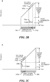
FIG 2A , the LADAR sensor, 102, is required to accommodate a very large range of target signal Doppler offsets, 220, and minimize the amount of intermediate frequency (IF) bandwidth, 224, that must be acquired and processed. For the technique described herein, a linear frequency modulation (FM) chirp signal orLO waveform 202 may be represented by a set of digital samples, 204, that spans the entire range of target Doppler frequency offsets, 220. Given atarget echo 206, a desiredLO waveform 208 is determined. The desiredLO waveform 208 has a corresponding subset ofdigital samples 210 and is synthesized by clocking thedigital samples 210 through a high speed digital to analog converter. - The
LO waveform 202 has a chirp slope of µ, which is the change in frequency, ΔF, per unit of time, ΔT. A Doppler estimate of the target echo, fDE, is used to determine the subset ofdigital samples 210 corresponding to the desiredLO waveform 208 starting at a time, two. The time, two is the Doppler estimate, fDE, divided by the chirp slope, µ. A LO waveform bandwidth, BWLO is also used to determine the subset ofdigital samples 210 of the desiredLO waveform 208. The BWLO is controlled by a number of waveform samples clocked from memory to a digital to analog converter (DAC). - Referring to
FIGS. 2B and 2C , atarget signal 216a is a received optical signal plus a blue Doppler shift and has apotential Doppler offset 220. Thesignal 216a has a desiredoptical LO waveform 218a. Atarget signal 216b is a received optical signal less a red Doppler shift and has apotential Doppler offset 220. Thesignal 216b has a desiredLO waveform 218b. As will be shown herein, knowledge of the sensor platform velocity VP and the squint angle, θS, enables a selection of the subset ofdigital samples 210a corresponding to the desiredLO waveform 218a in order to generate the proper optical heterodyne to generate aradio frequency signal 230a inside a receiverradio frequency bandwidth 224 and enables selection of the subset ofdigital samples 210b corresponding to the desiredLO waveform 218b in order to generate the proper optical heterodyne to generate aradio frequency signal 230b inside the receiverradio frequency bandwidth 224. - Referring to
FIG 3 , an example of a process to determine appropriate digital waveforms samples is aprocess 300.Process 300 determines an estimate of a position of a sensor (302). For example, an estimate of the position of thesensor 102, LSE is determined. For example, theGPS receiver 112 is used to determine an estimate of the position of thesensor 102, LSE. An estimate of the position, LSE, is determined since thesensor 102 is traveling on thesensor platform 106, and an exact position of the sensor LS is not known. -
Process 300 determines a location of the target, LT (304). For example, thesensor 102 determines the position of thetarget 104, LT. -
Process 300 determines an estimate of the range to target, RTE (306). For example, the estimate of the range to target, RTE, is the difference between the estimate of the location of the sensor, LSE, and the location of the target, LT. -
Process 300 converts the estimate of the range to target, RTE, to an estimate of the time to target, tRE (308). For example, the tRE is equal to two times the RTE divided by the speed of light. -
Process 300 determines an estimate of the velocity of the sensor platform, VPE (310). For example, theGPS receiver 112 is used to determine an estimate of the velocity of theplatform 106, LSE. -
Process 300 determines an estimate of a squint angle, θSE (312). For example, the squint angle, θSE, is determined based on the estimate of the location of the sensor, LSE. -
Process 300 determines an estimate of the Doppler value, fDE (314). For example, the estimate of the Doppler value, fDE, is determined from:
where λL is the laser wavelength of theLADAR sensor 102. -
Process 300 determines the digital samples of the LO waveform to use to form optical heterodyne (316). For example, the digital samples of the LO waveform to use is based on the estimate of the Doppler value, fDE and the LO waveform bandwidth, BWLO.Process 300 generates a signal with in a bandwidth of a receiver using the optical heterodyne (318). - Referring to
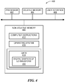
FIG 4 , acomputer 400 includes aprocessor 402, avolatile memory 404, anon-volatile memory 406 and a user interface (UI) 408 (e.g., a mouse, a keyboard, a display, a touch screen and so forth). Thenon-volatile memory 406stores computer instructions 412, anoperating system 416 and data 418 (e.g., digital samples of LO waveform 204). In one example, thecomputer instructions 412 are executed by theprocessor 402 out ofvolatile memory 404 to perform all or part of the processes described herein (e.g., the process 300). - The processes described herein (e.g., the process 300) are not limited to use with the hardware and software of
FIG 4 ; they may find applicability in any computing or processing environment and with any type of machine or set of machines that is capable of running a computer program. The processes described herein may be implemented in hardware, software, or a combination of the two. The processes described herein may be implemented in computer programs executed on programmable computers/machines that each includes a processor, a non-transitory machine-readable medium or other article of manufacture that is readable by the processor (including volatile and non-volatile memory and/or storage elements), at least one input device, and one or more output devices. Program code may be applied to data entered using an input device to perform any of the processes described herein and to generate output information. - The system may be implemented, at least in part, via a computer program product, (e.g., in a non-transitory machine-readable storage medium), for execution by, or to control the operation of, data processing apparatus (e.g., a programmable processor, a computer, or multiple computers)). Each such program may be implemented in a high level procedural or object-oriented programming language to communicate with a computer system. However, the programs may be implemented in assembly or machine language. The language may be a compiled or an interpreted language and it may be deployed in any form, including as a stand-alone program or as a module, component, subroutine, or other unit suitable for use in a computing environment. A computer program may be deployed to be executed on one computer or on multiple computers at one site or distributed across multiple sites and interconnected by a communication network. A computer program may be stored on a non-transitory machine-readable medium that is readable by a general or special purpose programmable computer for configuring and operating the computer when the non-transitory machine-readable medium is read by the computer to perform the processes described herein. For example, the processes described herein may also be implemented as a non-transitory machine-readable storage medium, configured with a computer program, where upon execution, instructions in the computer program cause the computer to operate in accordance with the processes. A non-transitory machine-readable medium may include but is not limited to a hard drive, compact disc, flash memory, non-volatile memory, volatile memory, magnetic diskette and so forth but does not include a transitory signal per se.
- The processes described herein are not limited to the specific examples described. For example, the
process 300 is not limited to the specific processing order ofFIG 3 . Rather, any of the processing blocks ofFIG 3 may be re-ordered, combined or removed, performed in parallel or in serial, as necessary, to achieve the results set forth above. - The processing blocks in
FIG. 3 associated with implementing the system may be performed by one or more programmable processors executing one or more computer programs to perform the functions of the system. All or part of the system may be implemented as special purpose logic circuitry (e.g., an FPGA (field programmable gate array) and/or an ASIC (application-specific integrated circuit)). - Elements of different embodiments described herein may be combined to form other embodiments not specifically set forth above. Other embodiments not specifically described herein are also within the scope of the following claims.
Claims (20)
- A method, comprising:representing a range of Doppler frequency offsets as a local oscillator waveform comprising a plurality of digital waveform samples;selecting a portion of the plurality of digital waveform samples using a Doppler value to form an optical heterodyne; andgenerating a signal associated with a target within a bandwidth of a receiver using the optical heterodyne.
- The method of claim 1, further comprising:determining a velocity of a platform;determining a squint angle between a line from a LADAR (laser detection and ranging) sensor disposed on the platform to the target and a nadir axis; anddetermining a Doppler value using the velocity of the platform, a wavelength of the LADAR sensor and the squint angle.
- The method of claim 2, further comprising:determining an estimated position of the LADAR sensor; anddetermining a location of the target;wherein determining a squint angle comprises determining an estimate of the squint angle using the estimated position of the LADAR sensor and the location of the target.
- The method of claim 3 wherein determining the estimated position of the LADAR sensor comprises determining the estimated position of the LADAR sensor using a GPS receiver, and
wherein determining the velocity of the platform comprises determining an estimated velocity of the platform using the GPS receiver. - The method of claim 2 wherein determining a Doppler value comprises determining an estimate Doppler value using the estimated velocity of the platform, a wavelength of the LADAR sensor and the estimate of the squint angle.
- The method of claim 5 wherein determining an estimate of the Doppler value comprises determining an estimate of the Doppler value, fDE, equal to:

where VPE is the estimated velocity of the sensor platform, θSE is the estimate of the squint angle, and λL is the wavelength of the LADAR sensor. - The method of claim 5, further comprising determining an estimated range to target based on the location of the target and the estimated position of the LADAR sensor.
- An article comprising:a non-transitory machine-readable medium that stores executable instructions, the instructions causing a machine to:represent a range of Doppler frequency offsets as a local oscillator waveform comprising a plurality of digital waveform samples;select a portion of the plurality of digital waveform samples using a Doppler value to form an optical heterodyne; andgenerate a signal associated with a target within a bandwidth of a receiver using the optical heterodyne.
- The article of claim 8, further comprising instructions causing the machine to:determine a velocity of a platform;determine a squint angle between a line from a LADAR (laser detection and ranging) sensor disposed on the platform to the target and a nadir axis; anddetermine the Doppler value using the velocity of the platform, a wavelength of the LADAR sensor and the squint angle.
- The article of claim 9, further comprising instructions causing the machine to:determine an estimated position of the LADAR sensor; anddetermine a location of the target;wherein the instructions causing the machine to determine a squint angle comprises instructions causing the machine to determine an estimate of the squint angle using the estimated position of the LADAR sensor and the location of the target.
- The article of claim 10 wherein the instructions causing the machine to determine the estimated position of the LADAR sensor comprises instructions causing the machine to determine the estimated position of the LADAR sensor using a GPS receiver, and
wherein the instructions causing the machine to determine the velocity of the platform comprises instructions causing the machine to determine an estimated velocity of the platform using the GPS receiver. - The article of claim 11 wherein the instructions causing the machine to determine a Doppler value comprises instructions causing the machine to determine an estimate Doppler value using the estimated velocity of the platform, a wavelength of the LADAR sensor and the estimate of the squint angle.
- The article of claim 12 wherein the instructions causing the machine to determine an estimate of the Doppler value comprises instructions causing the machine to determine an estimate of the Doppler value, fDE, equal to:

where VPE is the estimated velocity of the sensor platform, θSE is the estimate of the squint angle, and λL is the wavelength of the LADAR sensor. - An apparatus, comprising:circuitry to:represent a range of Doppler frequency offsets as a local oscillator waveform comprising a plurality of digital waveform samples;select a portion of the plurality of digital waveform samples using a Doppler value to form an optical heterodyne; andgenerate a signal associated with a target within a bandwidth of a receiver using the optical heterodyne.
- The apparatus of claim 14 wherein the circuitry comprises at least one of a processor, a memory, programmable logic and logic gates.
- The apparatus of claim 14, further comprising circuitry to:determine a velocity of a platform;determine a squint angle between a line from a LADAR (laser detection and ranging) sensor disposed on the platform to a target and a nadir axis; anddetermine the Doppler value using the velocity of the platform, a wavelength of the LADAR sensor and the squint angle.
- The apparatus of claim 16, further comprising circuitry to:determine an estimated position of the LADAR sensor; anddetermine a location of the target;
wherein the circuitry to determine a squint angle comprises circuitry to determine an estimate of the squint angle using the estimated position of the LADAR sensor and the location of the target. - The apparatus of claim 17 wherein the circuitry to determine the estimated position of the LADAR sensor comprises circuitry to determine the estimated position of the LADAR sensor using a GPS receiver,
wherein the circuitry to determine the velocity of the platform circuitry to determine an estimated velocity of the platform using the GPS receiver, and - The apparatus of claim 18 wherein the circuitry to determine a Doppler value comprises circuitry to determine an estimate Doppler value using the estimated velocity of the platform, a wavelength of the LADAR sensor and the estimate of the squint angle.
- The apparatus of claim 19 wherein the circuitry to determine an estimate of the Doppler value comprises circuitry to determine an estimate of the Doppler value, fDE, equal to:

where VPE is the estimated velocity of the sensor platform, θSE is the estimate of the squint angle, and λL is the wavelength of the LADAR sensor.
Applications Claiming Priority (1)
| Application Number | Priority Date | Filing Date | Title |
|---|---|---|---|
| US13/324,155 US8767187B2 (en) | 2011-12-13 | 2011-12-13 | Doppler compensation for a coherent LADAR |
Publications (2)
| Publication Number | Publication Date |
|---|---|
| EP2605042A1 true EP2605042A1 (en) | 2013-06-19 |
| EP2605042B1 EP2605042B1 (en) | 2018-03-07 |
Family
ID=45814426
Family Applications (1)
| Application Number | Title | Priority Date | Filing Date |
|---|---|---|---|
| EP12159971.6A Active EP2605042B1 (en) | 2011-12-13 | 2012-03-16 | Doppler compensation for a coherent LADAR |
Country Status (3)
| Country | Link |
|---|---|
| US (1) | US8767187B2 (en) |
| EP (1) | EP2605042B1 (en) |
| IL (1) | IL222552A (en) |
Families Citing this family (10)
| Publication number | Priority date | Publication date | Assignee | Title |
|---|---|---|---|---|
| US8767187B2 (en) | 2011-12-13 | 2014-07-01 | Raytheon Company | Doppler compensation for a coherent LADAR |
| US8947647B2 (en) | 2011-12-13 | 2015-02-03 | Raytheon Company | Range-resolved vibration using large time-bandwidth product LADAR waveforms |
| US8947644B2 (en) | 2012-01-19 | 2015-02-03 | Raytheon Company | Using multiple waveforms from a coherent LADAR for target acquisition |
| US9057605B2 (en) | 2012-12-06 | 2015-06-16 | Raytheon Company | Bistatic synthetic aperture ladar system |
| US10914825B2 (en) * | 2019-03-15 | 2021-02-09 | Raytheon Company | Technique for reducing impact of backscatter in coherent laser detection and ranging (LADAR) systems |
| US11933882B2 (en) * | 2019-08-20 | 2024-03-19 | Institut National D'optique | Method and system for detection and synthetic aperture imaging of a target |
| US11556000B1 (en) | 2019-08-22 | 2023-01-17 | Red Creamery Llc | Distally-actuated scanning mirror |
| US11754680B2 (en) | 2020-04-20 | 2023-09-12 | Raytheon Company | Optical system that detects and blocks backscatter |
| US11619709B2 (en) | 2020-04-20 | 2023-04-04 | Raytheon Company | Optical system to reduce local internal backscatter |
| GB2615364A (en) * | 2022-02-08 | 2023-08-09 | Royal Holloway & Bedford New College | A Doppler compensation method using photonic modulation |
Citations (3)
| Publication number | Priority date | Publication date | Assignee | Title |
|---|---|---|---|---|
| US3790278A (en) * | 1972-04-26 | 1974-02-05 | United Aircraft Corp | Peaked power coherent pulsed laser transmitter/receiver system |
| FR2519771A1 (en) * | 1982-01-08 | 1983-07-18 | Thomson Csf | Pulse compression LIDAR system - uses Doppler effect in reflected laser light to track moving target |
| EP0120775A1 (en) * | 1983-03-29 | 1984-10-03 | Thomson-Csf | Ranging and Doppler measuring laser apparatus using pulse compression |
Family Cites Families (30)
| Publication number | Priority date | Publication date | Assignee | Title |
|---|---|---|---|---|
| US4959800A (en) | 1988-05-20 | 1990-09-25 | Hughes Aircraft Company | Method and apparatus for determining the position and velocity of a target in inertial space |
| US5398130A (en) | 1992-12-01 | 1995-03-14 | The United States Of America As Represented By The Secretary Of The Army | Gradient index lens phased array phase compensation technique and apparatus |
| US5847816A (en) | 1997-01-14 | 1998-12-08 | Mcdonnell Douglas Corporation | Fiber optic micro-doppler ladar system and operating method therefor |
| US6545785B1 (en) | 1999-04-01 | 2003-04-08 | Trw Inc. | Optical communication system with phase modulation |
| US6259803B1 (en) | 1999-06-07 | 2001-07-10 | The United States Of America As Represented By The Secretary Of The Navy | Simplified image correlation method using off-the-shelf signal processors to extract edge information using only spatial data |
| US20060079773A1 (en) | 2000-11-28 | 2006-04-13 | Allez Physionix Limited | Systems and methods for making non-invasive physiological assessments by detecting induced acoustic emissions |
| US6388739B1 (en) | 2001-01-18 | 2002-05-14 | The Boeing Company | Self-referencing microdoppler ladar receiver and associated detection method |
| US6875978B2 (en) | 2001-06-11 | 2005-04-05 | Raytheon Company | Modelocked waveform for synthetic aperture ladar |
| US20030030882A1 (en) | 2001-08-13 | 2003-02-13 | Brian Garrett | Optical pulse generation |
| US7505488B2 (en) | 2001-09-28 | 2009-03-17 | Raytheon Company | Synthetic aperture ladar with chirped modelocked waveform |
| US6823033B2 (en) | 2002-03-12 | 2004-11-23 | Qualcomm Inc. | ΣΔdelta modulator controlled phase locked loop with a noise shaped dither |
| US6885299B2 (en) | 2002-05-24 | 2005-04-26 | Guy F. Cooper | Geopositionable expendable sensors and the use therefor for monitoring surface conditions |
| WO2004034530A1 (en) | 2002-10-08 | 2004-04-22 | Infinera Corporation | TRANSMITTER PHOTONIC INTEGRATED CIRCUIT (TxPIC) CHIPS |
| US6972846B2 (en) | 2003-03-31 | 2005-12-06 | Metrolaser, Inc. | Multi-beam heterodyne laser doppler vibrometer |
| US7474411B2 (en) | 2003-11-07 | 2009-01-06 | Lockheed Martin Corporation | System and method to reduce laser noise for improved interferometric laser ultrasound detection |
| GB0403468D0 (en) | 2004-02-17 | 2004-03-24 | Qinetiq Ltd | Laser vibrometer |
| US7805082B1 (en) | 2004-09-21 | 2010-09-28 | Ciena Corporation | Optical laser control for optical communications systems |
| US7414706B2 (en) | 2004-12-22 | 2008-08-19 | Northrop Grumman Corporation | Method and apparatus for imaging a target using cloud obscuration prediction and detection |
| AU2006254987B2 (en) | 2005-06-08 | 2010-07-29 | Massachusetts Institute Of Technology | Continuous, continental-shelf-scale monitoring of fish populations and behavior |
| JP4882042B2 (en) | 2006-06-23 | 2012-02-22 | 独立行政法人情報通信研究機構 | Ultrafast optical frequency sweep technology |
| EP1953567A3 (en) | 2007-01-25 | 2010-09-22 | Yamatake Corporation | Counting device, distance meter, counting method, and distance measuring method |
| TWI348555B (en) | 2007-10-30 | 2011-09-11 | Univ Nat Taiwan | Target detection device and its detection method |
| US8119971B2 (en) | 2008-01-17 | 2012-02-21 | Ball Corporation | Pulse data recorder in which a value held by a bit of a memory is determined by a state of a switch |
| DE602008002813D1 (en) | 2008-02-22 | 2010-11-11 | Thales Nederland Bv | Method for measuring the radial velocity of a target with a Doppler radar |
| JP2010026651A (en) | 2008-07-16 | 2010-02-04 | Toshiba Storage Device Corp | Automatic adjustment method for serial interface circuit and electronic device having serial interface circuit |
| US8487808B2 (en) | 2009-06-30 | 2013-07-16 | Mitsubishi Electric Research Laboratories, Inc. | High resolution SAR imaging using non-uniform pulse timing |
| US20130104661A1 (en) | 2011-10-31 | 2013-05-02 | Raytheon Company | Method and apparatus for range resolved laser doppler vibrometry |
| US8767187B2 (en) | 2011-12-13 | 2014-07-01 | Raytheon Company | Doppler compensation for a coherent LADAR |
| US8947647B2 (en) | 2011-12-13 | 2015-02-03 | Raytheon Company | Range-resolved vibration using large time-bandwidth product LADAR waveforms |
| US8947644B2 (en) | 2012-01-19 | 2015-02-03 | Raytheon Company | Using multiple waveforms from a coherent LADAR for target acquisition |
-
2011
- 2011-12-13 US US13/324,155 patent/US8767187B2/en active Active
-
2012
- 2012-03-16 EP EP12159971.6A patent/EP2605042B1/en active Active
- 2012-10-18 IL IL222552A patent/IL222552A/en active IP Right Grant
Patent Citations (3)
| Publication number | Priority date | Publication date | Assignee | Title |
|---|---|---|---|---|
| US3790278A (en) * | 1972-04-26 | 1974-02-05 | United Aircraft Corp | Peaked power coherent pulsed laser transmitter/receiver system |
| FR2519771A1 (en) * | 1982-01-08 | 1983-07-18 | Thomson Csf | Pulse compression LIDAR system - uses Doppler effect in reflected laser light to track moving target |
| EP0120775A1 (en) * | 1983-03-29 | 1984-10-03 | Thomson-Csf | Ranging and Doppler measuring laser apparatus using pulse compression |
Also Published As
| Publication number | Publication date |
|---|---|
| EP2605042B1 (en) | 2018-03-07 |
| US20130148095A1 (en) | 2013-06-13 |
| IL222552A (en) | 2016-06-30 |
| US8767187B2 (en) | 2014-07-01 |
Similar Documents
| Publication | Publication Date | Title |
|---|---|---|
| EP2605042B1 (en) | Doppler compensation for a coherent LADAR | |
| US8947647B2 (en) | Range-resolved vibration using large time-bandwidth product LADAR waveforms | |
| EP2871493B1 (en) | Position determination using synthetic wave laser ranging | |
| US9354304B2 (en) | Method for cyclically measuring distances and velocities of objects using an FMCW radar sensor | |
| US11852724B2 (en) | LIDAR system | |
| EP2618179B1 (en) | Using multiple waveforms from a coherent ladar for target acquisition | |
| US10261187B2 (en) | Optical phasograms for LADAR vibrometry | |
| JP2016029369A (en) | Frequency-modulated continuous wave (fmcw) radar equipped with timing synchronization | |
| US11714173B2 (en) | LIDAR system for autonomous vehicle | |
| EP3679394B1 (en) | Ladar system supporting doublet waveform for sequential in-phase (i) and quadrature (q) processing | |
| EP2871492B1 (en) | Synthetic wave laser ranging sensors and methods | |
| JP7291385B2 (en) | Optical measuring device and measuring method | |
| US20210026018A1 (en) | Operating method for a lidar system, control unit, lidar system, and device | |
| CN101788671B (en) | Multicycle modulation method applied to laser ranging device using chirp amplitude modulation based on heterodyne detection | |
| JP3716229B2 (en) | Radar equipment | |
| US20210373157A1 (en) | Ambiguity Mitigation for FMCW Lidar System |
Legal Events
| Date | Code | Title | Description |
|---|---|---|---|
| PUAI | Public reference made under article 153(3) epc to a published international application that has entered the european phase |
Free format text: ORIGINAL CODE: 0009012 |
|
| AK | Designated contracting states |
Kind code of ref document: A1 Designated state(s): AL AT BE BG CH CY CZ DE DK EE ES FI FR GB GR HR HU IE IS IT LI LT LU LV MC MK MT NL NO PL PT RO RS SE SI SK SM TR |
|
| AX | Request for extension of the european patent |
Extension state: BA ME |
|
| 17P | Request for examination filed |
Effective date: 20131219 |
|
| RBV | Designated contracting states (corrected) |
Designated state(s): AL AT BE BG CH CY CZ DE DK EE ES FI FR GB GR HR HU IE IS IT LI LT LU LV MC MK MT NL NO PL PT RO RS SE SI SK SM TR |
|
| 17Q | First examination report despatched |
Effective date: 20150319 |
|
| GRAP | Despatch of communication of intention to grant a patent |
Free format text: ORIGINAL CODE: EPIDOSNIGR1 |
|
| INTG | Intention to grant announced |
Effective date: 20170823 |
|
| GRAS | Grant fee paid |
Free format text: ORIGINAL CODE: EPIDOSNIGR3 |
|
| GRAJ | Information related to disapproval of communication of intention to grant by the applicant or resumption of examination proceedings by the epo deleted |
Free format text: ORIGINAL CODE: EPIDOSDIGR1 |
|
| GRAL | Information related to payment of fee for publishing/printing deleted |
Free format text: ORIGINAL CODE: EPIDOSDIGR3 |
|
| GRAR | Information related to intention to grant a patent recorded |
Free format text: ORIGINAL CODE: EPIDOSNIGR71 |
|
| GRAA | (expected) grant |
Free format text: ORIGINAL CODE: 0009210 |
|
| INTC | Intention to grant announced (deleted) | ||
| INTG | Intention to grant announced |
Effective date: 20180124 |
|
| AK | Designated contracting states |
Kind code of ref document: B1 Designated state(s): AL AT BE BG CH CY CZ DE DK EE ES FI FR GB GR HR HU IE IS IT LI LT LU LV MC MK MT NL NO PL PT RO RS SE SI SK SM TR |
|
| REG | Reference to a national code |
Ref country code: GB Ref legal event code: FG4D |
|
| REG | Reference to a national code |
Ref country code: CH Ref legal event code: EP Ref country code: AT Ref legal event code: REF Ref document number: 977155 Country of ref document: AT Kind code of ref document: T Effective date: 20180315 |
|
| REG | Reference to a national code |
Ref country code: FR Ref legal event code: PLFP Year of fee payment: 7 |
|
| REG | Reference to a national code |
Ref country code: IE Ref legal event code: FG4D |
|
| REG | Reference to a national code |
Ref country code: DE Ref legal event code: R096 Ref document number: 602012043584 Country of ref document: DE |
|
| REG | Reference to a national code |
Ref country code: NL Ref legal event code: MP Effective date: 20180307 |
|
| REG | Reference to a national code |
Ref country code: LT Ref legal event code: MG4D |
|
| PG25 | Lapsed in a contracting state [announced via postgrant information from national office to epo] |
Ref country code: CY Free format text: LAPSE BECAUSE OF FAILURE TO SUBMIT A TRANSLATION OF THE DESCRIPTION OR TO PAY THE FEE WITHIN THE PRESCRIBED TIME-LIMIT Effective date: 20180307 Ref country code: HR Free format text: LAPSE BECAUSE OF FAILURE TO SUBMIT A TRANSLATION OF THE DESCRIPTION OR TO PAY THE FEE WITHIN THE PRESCRIBED TIME-LIMIT Effective date: 20180307 Ref country code: NO Free format text: LAPSE BECAUSE OF FAILURE TO SUBMIT A TRANSLATION OF THE DESCRIPTION OR TO PAY THE FEE WITHIN THE PRESCRIBED TIME-LIMIT Effective date: 20180607 Ref country code: FI Free format text: LAPSE BECAUSE OF FAILURE TO SUBMIT A TRANSLATION OF THE DESCRIPTION OR TO PAY THE FEE WITHIN THE PRESCRIBED TIME-LIMIT Effective date: 20180307 Ref country code: LT Free format text: LAPSE BECAUSE OF FAILURE TO SUBMIT A TRANSLATION OF THE DESCRIPTION OR TO PAY THE FEE WITHIN THE PRESCRIBED TIME-LIMIT Effective date: 20180307 Ref country code: ES Free format text: LAPSE BECAUSE OF FAILURE TO SUBMIT A TRANSLATION OF THE DESCRIPTION OR TO PAY THE FEE WITHIN THE PRESCRIBED TIME-LIMIT Effective date: 20180307 |
|
| REG | Reference to a national code |
Ref country code: AT Ref legal event code: MK05 Ref document number: 977155 Country of ref document: AT Kind code of ref document: T Effective date: 20180307 |
|
| PG25 | Lapsed in a contracting state [announced via postgrant information from national office to epo] |
Ref country code: LV Free format text: LAPSE BECAUSE OF FAILURE TO SUBMIT A TRANSLATION OF THE DESCRIPTION OR TO PAY THE FEE WITHIN THE PRESCRIBED TIME-LIMIT Effective date: 20180307 Ref country code: SE Free format text: LAPSE BECAUSE OF FAILURE TO SUBMIT A TRANSLATION OF THE DESCRIPTION OR TO PAY THE FEE WITHIN THE PRESCRIBED TIME-LIMIT Effective date: 20180307 Ref country code: RS Free format text: LAPSE BECAUSE OF FAILURE TO SUBMIT A TRANSLATION OF THE DESCRIPTION OR TO PAY THE FEE WITHIN THE PRESCRIBED TIME-LIMIT Effective date: 20180307 Ref country code: BG Free format text: LAPSE BECAUSE OF FAILURE TO SUBMIT A TRANSLATION OF THE DESCRIPTION OR TO PAY THE FEE WITHIN THE PRESCRIBED TIME-LIMIT Effective date: 20180607 Ref country code: GR Free format text: LAPSE BECAUSE OF FAILURE TO SUBMIT A TRANSLATION OF THE DESCRIPTION OR TO PAY THE FEE WITHIN THE PRESCRIBED TIME-LIMIT Effective date: 20180608 |
|
| PG25 | Lapsed in a contracting state [announced via postgrant information from national office to epo] |
Ref country code: AL Free format text: LAPSE BECAUSE OF FAILURE TO SUBMIT A TRANSLATION OF THE DESCRIPTION OR TO PAY THE FEE WITHIN THE PRESCRIBED TIME-LIMIT Effective date: 20180307 Ref country code: NL Free format text: LAPSE BECAUSE OF FAILURE TO SUBMIT A TRANSLATION OF THE DESCRIPTION OR TO PAY THE FEE WITHIN THE PRESCRIBED TIME-LIMIT Effective date: 20180307 Ref country code: IT Free format text: LAPSE BECAUSE OF FAILURE TO SUBMIT A TRANSLATION OF THE DESCRIPTION OR TO PAY THE FEE WITHIN THE PRESCRIBED TIME-LIMIT Effective date: 20180307 Ref country code: RO Free format text: LAPSE BECAUSE OF FAILURE TO SUBMIT A TRANSLATION OF THE DESCRIPTION OR TO PAY THE FEE WITHIN THE PRESCRIBED TIME-LIMIT Effective date: 20180307 Ref country code: EE Free format text: LAPSE BECAUSE OF FAILURE TO SUBMIT A TRANSLATION OF THE DESCRIPTION OR TO PAY THE FEE WITHIN THE PRESCRIBED TIME-LIMIT Effective date: 20180307 Ref country code: PL Free format text: LAPSE BECAUSE OF FAILURE TO SUBMIT A TRANSLATION OF THE DESCRIPTION OR TO PAY THE FEE WITHIN THE PRESCRIBED TIME-LIMIT Effective date: 20180307 |
|
| REG | Reference to a national code |
Ref country code: CH Ref legal event code: PL |
|
| PG25 | Lapsed in a contracting state [announced via postgrant information from national office to epo] |
Ref country code: SM Free format text: LAPSE BECAUSE OF FAILURE TO SUBMIT A TRANSLATION OF THE DESCRIPTION OR TO PAY THE FEE WITHIN THE PRESCRIBED TIME-LIMIT Effective date: 20180307 Ref country code: SK Free format text: LAPSE BECAUSE OF FAILURE TO SUBMIT A TRANSLATION OF THE DESCRIPTION OR TO PAY THE FEE WITHIN THE PRESCRIBED TIME-LIMIT Effective date: 20180307 Ref country code: AT Free format text: LAPSE BECAUSE OF FAILURE TO SUBMIT A TRANSLATION OF THE DESCRIPTION OR TO PAY THE FEE WITHIN THE PRESCRIBED TIME-LIMIT Effective date: 20180307 Ref country code: CZ Free format text: LAPSE BECAUSE OF FAILURE TO SUBMIT A TRANSLATION OF THE DESCRIPTION OR TO PAY THE FEE WITHIN THE PRESCRIBED TIME-LIMIT Effective date: 20180307 |
|
| REG | Reference to a national code |
Ref country code: BE Ref legal event code: MM Effective date: 20180331 Ref country code: DE Ref legal event code: R097 Ref document number: 602012043584 Country of ref document: DE |
|
| REG | Reference to a national code |
Ref country code: IE Ref legal event code: MM4A |
|
| PG25 | Lapsed in a contracting state [announced via postgrant information from national office to epo] |
Ref country code: LU Free format text: LAPSE BECAUSE OF NON-PAYMENT OF DUE FEES Effective date: 20180316 Ref country code: PT Free format text: LAPSE BECAUSE OF FAILURE TO SUBMIT A TRANSLATION OF THE DESCRIPTION OR TO PAY THE FEE WITHIN THE PRESCRIBED TIME-LIMIT Effective date: 20180709 |
|
| PLBE | No opposition filed within time limit |
Free format text: ORIGINAL CODE: 0009261 |
|
| STAA | Information on the status of an ep patent application or granted ep patent |
Free format text: STATUS: NO OPPOSITION FILED WITHIN TIME LIMIT |
|
| PG25 | Lapsed in a contracting state [announced via postgrant information from national office to epo] |
Ref country code: IE Free format text: LAPSE BECAUSE OF NON-PAYMENT OF DUE FEES Effective date: 20180316 Ref country code: MC Free format text: LAPSE BECAUSE OF FAILURE TO SUBMIT A TRANSLATION OF THE DESCRIPTION OR TO PAY THE FEE WITHIN THE PRESCRIBED TIME-LIMIT Effective date: 20180307 Ref country code: DK Free format text: LAPSE BECAUSE OF FAILURE TO SUBMIT A TRANSLATION OF THE DESCRIPTION OR TO PAY THE FEE WITHIN THE PRESCRIBED TIME-LIMIT Effective date: 20180307 |
|
| 26N | No opposition filed |
Effective date: 20181210 |
|
| PG25 | Lapsed in a contracting state [announced via postgrant information from national office to epo] |
Ref country code: BE Free format text: LAPSE BECAUSE OF NON-PAYMENT OF DUE FEES Effective date: 20180331 Ref country code: SI Free format text: LAPSE BECAUSE OF FAILURE TO SUBMIT A TRANSLATION OF THE DESCRIPTION OR TO PAY THE FEE WITHIN THE PRESCRIBED TIME-LIMIT Effective date: 20180307 Ref country code: CH Free format text: LAPSE BECAUSE OF NON-PAYMENT OF DUE FEES Effective date: 20180331 Ref country code: LI Free format text: LAPSE BECAUSE OF NON-PAYMENT OF DUE FEES Effective date: 20180331 |
|
| PG25 | Lapsed in a contracting state [announced via postgrant information from national office to epo] |
Ref country code: MT Free format text: LAPSE BECAUSE OF NON-PAYMENT OF DUE FEES Effective date: 20180316 |
|
| PG25 | Lapsed in a contracting state [announced via postgrant information from national office to epo] |
Ref country code: TR Free format text: LAPSE BECAUSE OF FAILURE TO SUBMIT A TRANSLATION OF THE DESCRIPTION OR TO PAY THE FEE WITHIN THE PRESCRIBED TIME-LIMIT Effective date: 20180307 |
|
| PG25 | Lapsed in a contracting state [announced via postgrant information from national office to epo] |
Ref country code: HU Free format text: LAPSE BECAUSE OF FAILURE TO SUBMIT A TRANSLATION OF THE DESCRIPTION OR TO PAY THE FEE WITHIN THE PRESCRIBED TIME-LIMIT; INVALID AB INITIO Effective date: 20120316 |
|
| PG25 | Lapsed in a contracting state [announced via postgrant information from national office to epo] |
Ref country code: MK Free format text: LAPSE BECAUSE OF NON-PAYMENT OF DUE FEES Effective date: 20180307 |
|
| PG25 | Lapsed in a contracting state [announced via postgrant information from national office to epo] |
Ref country code: IS Free format text: LAPSE BECAUSE OF FAILURE TO SUBMIT A TRANSLATION OF THE DESCRIPTION OR TO PAY THE FEE WITHIN THE PRESCRIBED TIME-LIMIT Effective date: 20180707 |
|
| PGFP | Annual fee paid to national office [announced via postgrant information from national office to epo] |
Ref country code: FR Payment date: 20230222 Year of fee payment: 12 |
|
| PGFP | Annual fee paid to national office [announced via postgrant information from national office to epo] |
Ref country code: GB Payment date: 20230222 Year of fee payment: 12 Ref country code: DE Payment date: 20230221 Year of fee payment: 12 |
|
| P01 | Opt-out of the competence of the unified patent court (upc) registered |
Effective date: 20230530 |