EP2605027A2 - A switch-extender and a method for calibrating - Google Patents
A switch-extender and a method for calibrating Download PDFInfo
- Publication number
- EP2605027A2 EP2605027A2 EP12158439.5A EP12158439A EP2605027A2 EP 2605027 A2 EP2605027 A2 EP 2605027A2 EP 12158439 A EP12158439 A EP 12158439A EP 2605027 A2 EP2605027 A2 EP 2605027A2
- Authority
- EP
- European Patent Office
- Prior art keywords
- signal
- switch
- attenuator
- extender
- output
- Prior art date
- Legal status (The legal status is an assumption and is not a legal conclusion. Google has not performed a legal analysis and makes no representation as to the accuracy of the status listed.)
- Granted
Links
Images





Classifications
-
- H—ELECTRICITY
- H04—ELECTRIC COMMUNICATION TECHNIQUE
- H04L—TRANSMISSION OF DIGITAL INFORMATION, e.g. TELEGRAPHIC COMMUNICATION
- H04L25/00—Baseband systems
- H04L25/02—Details ; arrangements for supplying electrical power along data transmission lines
- H04L25/0202—Channel estimation
- H04L25/0204—Channel estimation of multiple channels
-
- G—PHYSICS
- G01—MEASURING; TESTING
- G01R—MEASURING ELECTRIC VARIABLES; MEASURING MAGNETIC VARIABLES
- G01R1/00—Details of instruments or arrangements of the types included in groups G01R5/00 - G01R13/00 and G01R31/00
- G01R1/20—Modifications of basic electric elements for use in electric measuring instruments; Structural combinations of such elements with such instruments
- G01R1/206—Switches for connection of measuring instruments or electric motors to measuring loads
-
- G—PHYSICS
- G01—MEASURING; TESTING
- G01R—MEASURING ELECTRIC VARIABLES; MEASURING MAGNETIC VARIABLES
- G01R31/00—Arrangements for testing electric properties; Arrangements for locating electric faults; Arrangements for electrical testing characterised by what is being tested not provided for elsewhere
- G01R31/28—Testing of electronic circuits, e.g. by signal tracer
- G01R31/2851—Testing of integrated circuits [IC]
- G01R31/2886—Features relating to contacting the IC under test, e.g. probe heads; chucks
- G01R31/2889—Interfaces, e.g. between probe and tester
-
- G—PHYSICS
- G01—MEASURING; TESTING
- G01R—MEASURING ELECTRIC VARIABLES; MEASURING MAGNETIC VARIABLES
- G01R35/00—Testing or calibrating of apparatus covered by the other groups of this subclass
- G01R35/005—Calibrating; Standards or reference devices, e.g. voltage or resistance standards, "golden" references
-
- H—ELECTRICITY
- H04—ELECTRIC COMMUNICATION TECHNIQUE
- H04L—TRANSMISSION OF DIGITAL INFORMATION, e.g. TELEGRAPHIC COMMUNICATION
- H04L25/00—Baseband systems
- H04L25/02—Details ; arrangements for supplying electrical power along data transmission lines
- H04L25/0264—Arrangements for coupling to transmission lines
-
- H—ELECTRICITY
- H04—ELECTRIC COMMUNICATION TECHNIQUE
- H04L—TRANSMISSION OF DIGITAL INFORMATION, e.g. TELEGRAPHIC COMMUNICATION
- H04L25/00—Baseband systems
- H04L25/02—Details ; arrangements for supplying electrical power along data transmission lines
- H04L25/0264—Arrangements for coupling to transmission lines
- H04L25/028—Arrangements specific to the transmitter end
-
- H—ELECTRICITY
- H04—ELECTRIC COMMUNICATION TECHNIQUE
- H04W—WIRELESS COMMUNICATION NETWORKS
- H04W24/00—Supervisory, monitoring or testing arrangements
- H04W24/06—Testing, supervising or monitoring using simulated traffic
-
- H—ELECTRICITY
- H04—ELECTRIC COMMUNICATION TECHNIQUE
- H04B—TRANSMISSION
- H04B3/00—Line transmission systems
- H04B3/02—Details
- H04B3/46—Monitoring; Testing
-
- H—ELECTRICITY
- H04—ELECTRIC COMMUNICATION TECHNIQUE
- H04L—TRANSMISSION OF DIGITAL INFORMATION, e.g. TELEGRAPHIC COMMUNICATION
- H04L25/00—Baseband systems
- H04L25/02—Details ; arrangements for supplying electrical power along data transmission lines
- H04L25/0202—Channel estimation
Definitions
- the present invention relates to a switch-extender and a method for calibrating a measurement system with such a switch-extender, especially for testing mobile communication systems, for example mobile phones, handhelds, tablet PCs and WLAN-routers.
- the approach of the present invention is that the overall test time can be reduced significantly by testing several mobile communication systems, like mobile phones, in parallel.
- Document US 2005/0264373 A1 describes a switching matrix that allows connecting multiple input ports to multiple output ports as well as to power sources. It is disadvantageous that document US 2005/0264373 A1 does not allow compensating different signal behavior in different signal path. Therefore, an input signal which is output at several ports has a different signal level which makes a switching matrix unsuitable for supplying a plurality of mobile communication systems in parallel with a test signal.
- the inventive switch-extender has at least one input port and several output ports, wherein the at least one input port and the several output ports are connected to a first Multiplexer/Demultiplexer-means (in the following MUX/DEMUX-means or -unit) wherein the first MUX/DEMUX-means connects the at least one input port to all output ports, wherein the MUX/DEMUX-means comprises at least one amplifier for amplifying a signal at the at least one input port and/or wherein the MUX/DEMUX-means comprises at least one attenuator for each of the output ports for attenuating a signal at every output port.
- a first Multiplexer/Demultiplexer-means in the following MUX/DEMUX-means or -unit
- the MUX/DEMUX-means connects the at least one input port to all output ports
- the MUX/DEMUX-means comprises at least one amplifier for amplifying a signal at the at
- At least one amplifier is connected to the at least one input port and/or the at least one attenuator is connected to each of the output ports. Therefore, a signal, which is split to different output-ports can be amplified to a certain signal level and then attenuated by an individual attenuation factor (attenuation value) to compensate for the individual signal path to obtain output signals having a predetermined signal level.
- an individual attenuation factor attenuation value
- the inventive method is used for calibrating a measurement system comprising a measurement unit, a switch-extender connected to the measurement unit and several signal connectors having one end connected to the switch-extender and several attenuators connected to an other end of the several signal connectors and one calibration system wherein a sequence of procedural steps are executed. First of all the other end of one signal connector is connected with an attenuator to the calibration system. Then a signal is generated with a specific signal level and/or a specific signal frequency with the measurement unit. After that a signal level and/or a signal frequency is measured with the calibration system at the output of the attenuator.
- a difference between the measured signal level and/or the measured signal frequency and the generated signal with the specific signal level and/or the specific signal frequency is determined.
- calibration data are calculated by using the determined difference between the measured signal level and/or the measured signal frequency and the generated signal with the specific signal level and/or the specific signal frequency.
- the signal connectors are used which are later also used for the measurement of the DUTs. This means that the determined difference and the calculated calibration data can be used later.
- a second attenuator is connected in series with the at least one attenuator and if the at least one attenuator has a larger attenuation range and higher attenuation steps than the second attenuator. This allows that the at least one attenuator is used as a coarse attenuator having a wide attenuation range and that the second attenuator can be used for a fine attenuation thereby allowing to adjust the attenuation factor (attenuation value defining the attenuation level) over a wide range accurately.
- a coupling-unit is connected between the least one attenuator or the second attenuator and the corresponding output port and if the coupling-unit has a third port at which a signal is transmitted that is input in the corresponding output port. This allows that the output port can be used as bidirectional port for the reflected and/or transmitted signal which is input thereto as well.
- At least one input port and several output ports are connected to a second MUX/DEMUX-unit wherein the second MUX/DEMUX-unit comprises the same elements as the first MUX/DEMUX-unit with the difference that the at least one input port is connected to a switch and if one output port of the switch is connected to an input port of an amplifier and if an other output port of the switch is connected to an output port of another amplifier so that the at least one input port acts as bidirectional port.
- This allows that the only input port of the second MUX/DEMUX-unit that is connected to the measurement unit can be used as a bidirectional port.
- a DUT connected to the output port of the second MUX/DEMUX-unit can therefore transmit a signal to the second MUX/DEMUX-unit that will be forwarded to the measurement unit.
- the switch-extender comprises a plurality of first MUX/DEMUX-units and a plurality of second MUX/DEMUX-units wherein the input ports of the plurality of second MUX/DEMUX-units are connected to an input port of a multiplexer, wherein the output port of each multiplexer is connected to at least one amplifier of each of the plurality of the second MUX/DEMUX-units and wherein the output ports of each multiplexer are connected to the output of another amplifier of each of the plurality of the second MUX/DEMUX-units.
- every second MUX/DEMUX-unit can multiply the number of output ports addressable by the individual MUX/DEMUX-unit by the number of other MUX/DEMUX-units. Therefore, DUTs having more antennas can be tested without difficulties.
- the switch-extender further comprises a processing unit and a storage unit connected to each other wherein the processing unit controls the amplification settings of the at least one amplifier and wherein the processing unit also controls the attenuation settings of the at least one attenuator so that the signal has at every output port a predetermined signal level for every frequency. This ensures that the switching times are reduced to a minimum, so that changes in the signal level resulting from changes in the frequency of operation can be compensated fast.
- the method for calibrating a measurement system includes the switch-extender that further comprises at least one attenuator or at least one attenuator and a second attenuator in series for every output port and that the attenuation factor of the at least one attenuator is adjusted or that the attenuation factor of the at least one attenuator and the second attenuator is adjusted, so that the measured signal level and/or signal frequency of the signal is equal to the generated signal with the specific signal level and/or the specific signal frequency.
- the switch-extender that further comprises at least one attenuator or at least one attenuator and a second attenuator in series for every output port and that the attenuation factor of the at least one attenuator is adjusted or that the attenuation factor of the at least one attenuator and the second attenuator is adjusted, so that the measured signal level and/or signal frequency of the signal is equal to the generated signal with the specific signal level and/or the specific signal frequency.
- Fig. 1 shows the basic principle of the present invention. It shows a measurement system 1 which is used for generating a test signal (downlink signal) and which is also used for measuring a signal transmitted from the DUTs (uplink signal). Therefore, the measurement system 1 comprises a TRX unit 2 (transmit receive) which is used for generating the base band and/or the RF (radio frequency). Furthermore the measurement system 1 also comprises a frontend 3 which comprises a reference circuit and which divides the signal from or to the TRX unit 2 into three input or output ports. For example, there is a first port "RF1Out” which is used to output the test signal (downlink signal) that is normally a high frequency signal, like a GSM or UMTS (CDMA signal in generally).
- RF1Out a first port "RF1Out” which is used to output the test signal (downlink signal) that is normally a high frequency signal, like a GSM or UMTS (CDMA signal in generally).
- RF1COM test signal
- uplink signal uplink signal
- RF2COM third port
- RF2COM can also be used to output the test signal (downlink signal) and which can also be used to input a signal (uplink signal) transmitted from the mobile communication system 7 (device under test - DUT).
- the switch-extender 4 comprises a first MUX/DEMUX-unit 5 having a ratio of one to eight.
- the switch-extender 4 according to the present invention may also have a second MUX/DEMUX-unit 6 which has a ratio of one to four.
- the second MUX/DEMUX-unit 6 is optional. However, other ratios are also possible.
- the switch- extender 4 will be described in the following in detail.
- the switch-extender 4 is preferably connected to several mobile communication systems 7, also called devices under test (DUT). This connection is done by using a cable connection.
- DUTs 7 1 , 7 2 , 7 3 , 7 4 there are four devices under test, also called DUTs 7 1 , 7 2 , 7 3 , 7 4 .
- the DUTs can be a mobile phone or a handheld PC or a tablet PC or a pocket PC or even a WLAN router.
- each of the DUTs 7 1 , 7 2 , 7 3 , 7 4 has at least three antennas.
- a DUT 7 1 , 7 2 , 7 3 , 7 4 has also more or less than three antennas.
- each DUT 7 1 , 7 2 , 7 3 , 7 4 also shows that two antennas of each DUT 7 1 , 7 2 , 7 3 , 7 4 are connected to the MUX/DEMUX-unit 5 of the switch-extender 4. Those antennas are used for communication by using the MIMO (Multiple Input, Multiple Output) technique.
- a third antenna of each DUT 7 1 , 7 2 , 7 3 , 7 4 is connected to the second MUX/DEMUX-unit 6.
- the third antenna can be used for GPS or WLAN. It can also be used for Bluetooth or other communication standards.
- the antennas of the DUT 7 1 , 7 2 , 7 3 , 7 4 and the cable connection are not matched. Therefore, an attenuator is used between the cable and the antenna. Normally a 3 dB attenuator is used as shown in Fig. 1 . Using a 3 dB attenuator, the reflected wave from the antenna of the DUT has a signal level which is 6 dB lower than the signal level of the signal (downlink) which is transmitted from the measurement system 1 over the switch-extender 4 to the antennas of the DUT 7 1 , 7 2 , 7 3 , 7 4 .
- the second MUX/DEMUX-unit 6 is only used for none-cellular applications like WLAN, Bluetooth or GPS or the like. If the DUT uses only one antenna for cellular applications (none-MIMO) the switch-extender 4 can support up to eight DUTs.
- the second MUX/DEMUX-unit 6 If the second MUX/DEMUX-unit 6 is used, the none-cellular applications (WLAN, Bluetooth and/or GPS) are tested first, since the cellular chips (CDMA-chips) need more time to come up.
- the measurement system 1 generates a base band-signal (downlink) in the TRX-unit 2. This signal (downlink) is then sent to the MUX/DEMUX-unit 6 using the third port "RF2COM" of the second MUX/DEMUX unit 6.
- the second MUX/DEMUX-unit 6 connects the third port of the measurement system 1 to the third antenna of the first DUT 7 1 . After the test signal is sent, the first DUT 7 1 is processing it.
- the first DUT 7 1 After the first DUT 7 1 has processed the test signal, it outputs the results, for example the current GPS-position using the third antenna or a data bus which is not shown.
- the second MUX/DEMUX-unit 6 still connects the third antenna to the third port "RF2COM" of the measurement system 1.
- the measurement system 1 can analyze if the calculated results of the first DUT 7 1 are correct. If the none-cellular applications are tested for the first DUT 7 1 , the second MUX/DEMUX-unit 6 connects the third port of the frontend 3 of the measurement system 1 to the third antenna of the second DUT 7 2 .
- the second MUX/DEMUX-unit 6 connects all DUTs 7 1 , 7 2 , 7 3 , 7 4 one after another to the third port of the measurement system 1.
- the second MUX/DEMUX-unit 6 can also connect DUTs to another port of the measurement system 1 as long as this port can also be used for transmitting and receiving signals.
- the second MUX/DEMUX-unit 6 can also be connected to the second port "RF1COM" of the measurement system 1.
- the measurement system 1 If the measurement of the none-cellular applications of the DUTs 7 1 , 7 2 , 7 3 , 7 4 is done, the cellular chips of the DUTs 7 1 , 7 2 , 7 3 , 7 4 are up for operation. Now the measurement system 1 generates and transmits test signals to the first MUX/DEMUX-unit 5. The signals are generated in the TRX-unit 2 and are sent by using the first port "RF1OUT" of the frontend 3. This test signal is then split into eight signals and transmitted to the first and to the second antenna of each of the four DUTs 7 1 , 7 2 , 7 3 , 7 4 .
- the test signal can comprise a really long sequence that is used to calculate the bit error rate (BER) of each of the DUTs.
- BER bit error rate
- each of the DUTs 7 1 , 7 2 , 7 3 , 7 4 receives a long sequence which is used to calculate the bit error rate. If the DUTs have calculated the bit error rate, the first MUX/DEMUX-unit 5 connects one DUT after another to the second port "RF1COM" of the measurement system 1. The measurement system 1 then measures the uplink signal from each of the DUTs 7 1 , 7 2 , 7 3 , 7 4 .
- Fig. 2 shows a measurement system 1 which comprises two separate TRX-units 2, 8 and two separate frontends 3, 9.
- the switch-extender 4 also comprises a first MUX/DEMUX-unit 5 and optionally a second MUX/DEMUX-unit 6 as described above.
- the switch-extender 4 comprises also a further MUX/DEMUX-unit 10 having also a ratio of one to eight and a MUX/DEMUX-unit 11 having a ratio of one to four.
- the MUX/DEMUX-unit 11 is also optional.
- DUTs 12 1 , 12 2 , 12 3 , 12 4 are connected to the further MUX/DEMUX-unit 10 and to the MUX/DEMUX-unit 11 as described above referring to the DUTs 7 1 , 7 2 , 7 3 , 7 4 .
- Fig. 3 shows a detailed schematic diagram of the first MUX/DEMUX-unit 5 according to the present invention. It can be seen that the first MUX/DEMUX-unit 5 is divided into two parts. The first part is the transmission path and the second part is the receiving path. The transmission path is used to transmit a signal (downlink signal) from measurement system 1 to the DUTs 7 1 to 7 4 in parallel and the receiving path is used to transmit a signal (uplink signal) from the DUTs 7 1 to 7 4 to the measurement system 1. The transmission path is connected to the first port "RF1Out" of the frontend 3 of the measurement system 1.
- the downlink signal is split using a signal splitter 30, like a Wilkinson divider, into two signals, both having preferably the same signal level.
- Each output port of the signal splitter 30 is then connected to a switch 31 1 , 31 2 .
- One output port of each switch 31 1 , 31 2 is not connected to anything, so the switch can be used to decouple the specific signal path at all.
- Normally the other output port of the switch 31 1 , 31 2 is used to connect each output of the signal splitter 30 to an amplifier 32 1 , 32 2 .
- the amplifiers 32 1 , 32 2 can be used to amplify the signal by 0 to +20 dB.
- the output of each of the amplifiers 32 1 , 32 2 is then connected to another signal splitter 33 1 , 33 2 .
- Each output port of the further signal splitters 33 1 , 33 2 is then connected with another signal splitter 34 1 , 34 2 , 34 3 , 34 4 .
- the downlink signal which is generated by the TRX-Unit 2 is split up and amplified into eight equal signals. Those signals can be used for four DUTs 7 1 , 7 2 , 7 3 , 7 4 , each of them having up to two cellular antennas operating in MIMO-mode.
- each signal path that is used for carrying one of the split downlink signals comprises two attenuators arranged in series. Therefore, each output port of the further signal splitters 34 1 , 34 2 , 34 3 , 34 4 is connected to a first attenuator 36 1 , 36 2 , 36 3 , 36 4 , 36 5 , 36 6 , 36 7 and 36 8 .
- Those first attenuators 36 1 are 36 8 are also called step-attenuators.
- Those attenuators can be used to attenuate the split downlink signal in steps of approximately 1 ⁇ 4 dB from 0 to 31 dB.
- the output port of each the first attenuators of each signal path is then connected to a second attenuator 37 1 , 37 2 , 37 3 , 37 4 , 37 5 , 37 6 , 37 7 and 37 8 .
- the second attenuators are also called fine attenuators. They allow attenuating the split downlink signal in steps of approximately a 2 mdB.
- each output port of the level adjustment unit 35 or, to be more precise, each output port of the second attenuator is connected to one coupling-unit 38 1 to 38 8 .
- the use of each coupling-unit is that the downlink signal which is split into up to eight individual downlink signals is transmitted to the first and to the second antenna of each DUT and that the uplink signal which is transmitted from the first and the second antenna of each DUT is transmitted back to the second output port "RF1COM" of the measurement system 1. Therefore, the coupling-unit 38 1 to 38 8 prevents an uplink signal which is transmitted from the DUTs to travel across the downlink signal path.
- the coupling-unit 38 1 to 38 8 is preferably a directional coupling-unit 38 1 to 38 8 , so that the uplink signal exits the directional coupling-unit 38 1 to 38 8 through another port.
- the directional coupling-unit 38 1 to 38 8 comprises three attenuators and three resistors, for example connected in a T-structure.
- Each output port RF1 to RF8 is connected to the first or to the second antenna of each DUT 7 1 , 7 2 , 7 3 , 7 4 using a cable and several connectors.
- the task of the switch-extender 4 according to the present invention is that the downlink signal at the first and the second antenna of each of the DUTs 7 1 , 7 2 , 7 3 , 7 4 has the same predetermined signal level.
- the level adjustment unit 35 allows a coarse and a fine tuning of the split downlink signals. Since the first and the second attenuator within the level adjustment unit 35 are built by using transistors or the like, the signal can be attenuated within 300 microseconds or less. Relays which are used in the state of the art are preferably not used within the present invention at all.
- the signal level of the downlink signal is very low, for example -100 dBm.
- the third output ports RX1 to RX8 of each of the coupling-units 38 1 to 38 8 are connected to a multiplexer 39 1 , 39 2 .
- Each of the multiplexers 39 1 , 39 2 have four input ports for example and one output port. Therefore, the uplink signal which is transmitted from the first and the second DUT 7 1 , 7 2 is available at the first multiplexer 39 1 and the uplink signal which is transmitted from the third and the fourth DUT 7 3 , 7 4 is available at the second multiplexer 39 2 . This is done by using the coupling-units 38 1 to 38 8 as described above.
- each multiplexer 39 1 , 39 2 is connected to another attenuator 40 1 , 40 2 .
- These attenuators 40 1 , 40 2 are able to attenuate an uplink signal coarsely.
- the attenuators 40 1 , 40 2 can attenuate an uplink signal in steps of 0 dB, -13 dB and -26 dB. It is also possible to use an attenuator 40 1 , 40 2 which attenuates an uplink signal in much smaller steps.
- the attenuation factor of the attenuator 40 1 , 40 2 is selected to the highest possible value, in this example - 26 dB. If the DUT transmits an uplink signal with a signal level of 0 dBm the attenuator 40 1 , 40 2 selects the lowest possible attenuation factor, in this example 0 dB.
- each of the attenuators 40 1 , 40 2 is connected to an amplifier 41 1 , 41 2 .
- Each amplifier 41 1 , 41 2 amplifies the input signal to an output signal having a desired signal level.
- the amplifier factor is chosen so that the measurement system 1 measures the uplink signal with the highest possible precision.
- each amplifier is connected to a switch 42.
- a control unit within the switch-extender 4 or within the measurement system 1 selects the uplink signal from one antenna of one of one DUT 7 1 , 7 2 , 7 3 , 7 4 to be measured within the measurement system 1.
- the output port of the switch 42 is then connected to the second port "RF1COM" of the measurement system 1. It can also be connected to the third port "RF2COM" or to any port within the measurement system 1 which allows inputting an uplink signal for further analyses.
- FIG. 3 can also be used within the further MUX/DEMUX-unit 10 as shown in Fig. 2 .
- the level adjustment unit 35 selects an attenuation value for the first attenuators 36 1 to 36 8 and for the second attenuators 37 1 to 37 8 which is based on the individual cable and connectors as well as on the individual signal path.
- the correction data is obtained for each frequency point for each signal path as well as for each cable and connector. Therefore, if the frequency band for which the downlink signal is transmitted is changed, all attenuators within the level adjustment unit 35 have to be set for their new attenuation factor.
- the amplifiers 32 1 , 32 2 and 41 1 , 41 2 as well as the attenuators 40 1 , 40 2 may also need to be set for the new frequency. This is done preferably very fast in less than 300 microseconds.
- the control of the level adjustment unit 35 as well as of the amplifiers 32 1 , 32 2 , as well as of the amplifiers 41 1 , 41 2 and as well as of the attenuator 40 1 , 40 2 can be done in three different ways.
- the aforementioned components can be connected to the measurement system 1 directly. However, only very fast connection types are recommended. This could be done by an interface with a lot of parallel data lines applying a high clock rate.
- the measurement system 1 selects all attenuation factors as well as all amplifier factors for the selected frequency of operation of the downlink signal. This information can be extracted from calibration data which will be discussed below. SPI-commands allow those components to be programmed by the measurement system 1.
- a more preferred second possibility for adjusting the aforementioned components can be done by incorporating a processing unit 45 within the switch-extender 4.
- the processing unit is connected to the level adjustment unit 35 and therein with the first attenuators and the second attenuators.
- the processing unit 45 is further connected to the amplifier 32 1 , 32 2 , 41 1 , 41 2 as well as to the attenuators 40 1 , 40 2 and optional to the multiplexers 39 1 , 39 2 and the switches 31 1 , 31 2 , 42.
- the processing unit is also connected to the measurement system 1.
- the measurement system 1 then signals the processing unit 45 the values of the attenuation and/or the amplification factors to be set and optional the position of the switches and the multiplexers.
- the communication itself between the processing unit 45 and the components within the switch-extender 4 is done without any knowledge of the measurement system 1.
- the processing unit 45 can communicate by using the SPI-commands on a single line or by using parallel data lines.
- a third possibility is that the processing unit 45 only receives the frequency and the signal level of the downlink signal which is transmitted by the measurement system 1.
- the processing unit 45 then alternates all attenuation factors or amplification factors by itself. Therefore, besides the processing unit 45 a further storage unit 46 is needed where all calibration data are stored. This could be done by using a lookup-table comprising all attenuation factors and/or amplification factors needed for an individual signal level as well as for an individual signal frequency.
- the processing unit 45 then reads out the storage unit 46 and alternates those factors as required.
- Fig. 3 it is possible to transmit a downlink signal on eight signal paths in parallel.
- the multiplexer 39 1 , 39 2 or the switch 42 have to be changed. This can also be done by the processing unit 45 or by the measurement system 1 directly. Therefore, the multiplexer 39 1 , 39 2 as well as the switch have to be connected to the processing unit 45 and/or to the measurement system 1. This can also be done by well known data connection types or by a parallel interface. The same also applies for the further MUX/DEMUX-unit 10.
- Fig. 4 shows a schematic diagram of the second MUX/DEMUX-unit 6 as well as of the MUX/DEMUX-unit 11 according to the present invention.
- the second MUX/DEMUX-unit 6 is used to measure the none-cellular applications within the DUT 7 1 , 7 2 , 7 3 , 7 4 .
- the measurement system 1 in particular the TRX-unit 2 and the frontend 3 generate a downlink signal which is output at the third output port "RF2COM".
- the second TRX-unit 8 and the second frontend 9 the subject matter as explained in detail above stays the same. It only differs in the names used for the reference signs.
- the third port “RF2COM” can be used to output a downlink signal or to input an uplink signal.
- the output port "RF2COM” is connected to a switch 50.
- One output port of the switch 50 is connected to another switch 51.
- One output of the switch 51 is connected to an amplifier 52.
- the amplifier 52 is used to amplify the downlink signal by 0 to +20 dB.
- the output of the amplifier 52 is connected to a signal splitter 53.
- the signal splitter 53 can be a Wilkinson divider.
- Each output port of the signal splitter 53 is connected to an input port of another signal splitter 54 1 , 54 2 .
- Each output port of the further signal splitters 54 1 , 54 2 is connected to the second level adjustment unit 55.
- the second level adjustment unit 55 comprises the same structure as the level adjustment unit 35 as described in Fig. 3 .
- the second level adjustment unit 55 only comprises four signal paths. In each signal paths, there are two attenuators arranged in series.
- a first attenuator 56 1 , 56 2 , 56 3 , 56 4 is used to attenuate the split downlink signal in a coarse step.
- the first attenuator 56 1 to 56 4 can attenuate the split downlink signal in steps of 1-4 dB over a range from 0 to 31 dB.
- the output port of the first attenuator 56 1 to 56 4 is then connected to an input port of a second attenuator 57 1 , 57 2 , 57 3 , 57 4 .
- the second attenuator is used to attenuate the split downlink signal in finer steps.
- the second attenuators 57 1 to 57 4 can attenuate a signal in steps of 2 mdB or the like.
- the output port of the second attenuators 57 1 to 57 4 is then connected to a coupling-unit 58 1 to 58 4 .
- the design of the coupling-unit 58 1 to 58 4 as shown in Fig. 4 is the same as the design of the coupling-unit 38 1 to 38 8 as shown in Fig. 3 so that a reference is made to the description above.
- the second output port RF1 to RF4 of the coupling-unit 58 1 to 58 4 is connected to the third antenna of the DUTs 7 1 , 7 2 , 7 3 , 7 4 .
- the second level adjustment unit 55 makes sure that the level of the downlink signal is the same for all signal paths at the third antenna of each DUT 7 1 , 7 2 , 7 3 , 7 4 . This is done by using calibration data of the cable and the connector as well as of each individual signal path. The amplification as well as the attenuation value of each attenuator is selected in such a way that different frequency behaviors over a frequency span are compensated. This also applies for different signal levels. Therefore, every downlink signal frequency and every downlink signal level corresponds to a separate data set which includes the calibration data that is used for setting the amplifier 52 and the first attenuator 56 1 to 56 4 and the second attenuator 57 1 to 57 4 properly.
- the uplink signal transmitted from the third antenna of each DUT 7 1 , 7 2 , 7 3 , 7 4 is decoupled within the coupling-unit 58 1 to 58 4 to the third output port RX1 to RX4.
- the third output port RX1 to RX4 of all coupling-units 58 1 to 58 4 are connected to a multiplexer 59.
- the multiplexer has four input ports connected to each of the coupling-units 58 1 to 58 4 and one output port connected to an attenuator 60.
- the attenuator 60 attenuates the uplink signal in a coarse way. For example, an attenuation factor of 0, -13, -26 dB can be selected.
- the output port of the attenuator 60 is then connected to the input port of an amplifier 61.
- the amplifier 61 is then connected to the second "output" port of the switch 50.
- the switch 50 then connects the output port of the amplifier 61 to the third port "RF2COM" of the measurement system 1.
- the attenuator 60 is thereby selected to attenuate a strong signal with a higher attenuation factor than a weak signal. For example, if the DUT transmits an uplink signal having a signal level 30 dB, the attenuator 60 attenuates this signal by -26 dB. On the other hand, if the DUT transmits a signal having a signal level of 0 dB, the attenuator 60 attenuates this signal with 0 dB. Other values are also possible.
- the amplifiers 52, 61 and the attenuators 56 1 to 56 4 and 57 1 to 57 4 and 60 are controlled by the measurement system 1 directly or by the processing unit 45.
- the same also applies for the switch 50, the switch 51 and the multiplexer 59.
- the switch 51 can be used to separate the transmitting path from the receiving path in order to increase the isolation between them.
- the components can be controlled by the measurement system 1 directly.
- the measurement system 1 sets all switch positions and/or all attenuation and/or amplification factors.
- the measurement system 1 can signal the processing unit 45 the switching positions and the amplification and/or attenuation factors.
- the third possibility is that the measurement system 1 only informs the processing unit 45 about the frequency and the signal level of the downlink signal and/or the number of the DUT which has to be measured in the uplink path.
- the processing unit 45 then reads the settings from a storage unit 46 and makes the needed adjustments.
- Fig. 5 shows a 3-dimensional view of the exemplary embodiment of the switch-extender 4 according to the present invention.
- the switch-extender 4 comprises a series of input and/or output ports.
- the ports for connecting the switch-extender 4 to the measurement system 1 are located on the right side of the switch-extender 4.
- Fig. 5 shows the ports "RF1Out”, RF1COM” and “RF2COM” for connecting the switch-extender 4 to the first frontend 3 within the measurement system 1.
- Fig. 5 also shows the ports "RF3Out”, "RF3COM” and "RF4COM” for connecting the switch-extender 4 to the second frontend 9 within the measurement system 1.
- the ports for connecting the switch-extender 4 to the measurement system 1 are shown on the right, but they can also be located anywhere on the front or the rear panel of the switch-extender 4.
- the other ports are used for connecting the switch-extender 4 to the series of antennas of the DUTs 7 1 , 7 2 , 7 3 , 7 4 and 12 1 to 12 4 .
- eight ports on the bottom row from left to right represent the output and/or input ports of the MUX/DEMUX-unit 5 as shown in Fig. 3 . Within Fig. 3 these ports are named RF1 to RF8.
- the top row comprises the input and/or output ports for the further MUX/DEMUX-unit 10 which is connected to the second frontend 9. With respect to Fig. 2 , also eight ports are used therefor.
- the row in the middle is used for the second MUX/DEMUX-unit 6 as well as for the MUX/DEMUX-unit 11.
- the four ports from left to right represent the output and/or input ports of the second MUX/DEMUX-unit 6, whereas the four ports following on the right represent the input and/or output ports of the MUX/DEMUX-unit 11.
- the input and/or output ports can be arranged in different ways. Beside every port, there are two LEDs 70 1 , 70 2 . Those LEDs 70 1 , 70 2 indicate whether the individual port is used as an output port or an input port.
- All ports are mounted directly on a printed circuit board. Preferably there are no cable connections. There is normally one printed circuit board for each row using connectors to connect the individual printed circuit boards together. All printed circuit boards are controlled by a central processing unit 45. However, as described above, the ports can also be controlled by the measurement system 1 itself.
- Fig. 6 shows a further exemplary embodiment of a schematic diagram according to the present invention.
- the output and/or input ports in the middle of the row are shared between the first frontend 3 and the second frontend 9.
- One possibility on how to connect these ports with the measurement system 1 is shown in Fig. 4 .
- the first frontend 3 and for the second frontend 9 to use the output ports of the switch-extender 4 from each another.
- the first frontend 3 can only address four DUTs 7 1 , 7 2 , 7 3 , 7 4 each having one third antenna.
- the second frontend 9 can also only address four DUTs 12 1 to 12 4 each having one third antenna.
- some DUTs may have more than three antennas. Therefore, it would be desirable if the first frontend 3 could also use the output and/or input ports of the switch-extender 4 linked to the second frontend 9.
- Fig. 6 describes a possibility that allows the first frontend 3 to use the input and/or output ports of the second MUX/DEMUX-unit 6 as well as the input and/or output ports of the MUX/DEMUX-unit 11.
- Fig. 6 also shows the possibility for the second frontend 9 to use the input and/or output ports of the MUX/DEMUX-unit 11 as well as the input and/or output ports of the second MUX/DEMUX-unit 6.
- the port “RF2COM” is connected to a multiplexer 80 and the port “RF4COM” is connected to a multiplexer 81.
- the ports “RF2COM” and “RF4COM” are bidirectional ports which can be used as output ports as well as input ports. Therefore, the wording "multiplexer” is always used instead of the wording "demultiplexer”.
- One output port of the multiplexer 80 can be connected to the transmit path as shown in Fig. 4 .
- the transmit path comprises another switch 82 and the well-known circuit elements 52, 53, 54 1 , 54 2 , 55 and 58 1 to 58 4 .
- a second output of the multiplexer 80 can also be connected to the second transmit path which was only used in Fig. 4 by the second frontend 9.
- the second output of the multiplexer 80 is therefore connected to a switch 83 and in row to the switch 83 to a signal splitter 84.
- One outfit of the splitter 84 is connected to the switch 82 and the other output of the signal splitter is connected to the switch 85.
- the output of the switch 85 is thereby connected to the second signal path.
- the circuit elements of the second signal path are the same as the circuit elements of the first signal path.
- the uplink signal namely the signal which is transmitted from the third antenna of the DUT 7 1 , 7 2 , 7 3 , 7 4 as well as for the uplink signal which is transmitted from the third antenna of the DUT 12 1 to 12 4 .
- coupling-units 58 1 to 58 4 are used to decouple the uplink signal transmitted by the third antenna of the DUT 7 1 , 7 2 , 7 3 , 7 4 .
- the uplink signal is decoupled at the third port of the coupling-unit 58 1 , to 58 4 .
- These ports are called RX1 to RX4. These ports are connected to a multiplexer 59.
- the multiplexer 59 selects one uplink signal at the same time and forwards it to an attenuator 60.
- the output of the attenuator 60 is connected to an amplifier 61. This subject matter is also described with respect to Fig. 4 .
- the output of the amplifier 61 is connected to a switch 86.
- the output of the switch 86 is connected to the multiplexer 80.
- the uplink path of the DUTs 12 1 to 12 4 The uplink signal transmitted from the DUTs 12 1 to 12 4 is decoupled by the coupling-units 87 1 to 87 4 . Those coupling-units are integrated within a switch-extender 4 in the MUX/DEMUX-unit 11.
- the uplink signal is then fed to a multiplexer 88.
- the multiplexer 88 selects one uplink signal at the same time and forwards it to another attenuator 89.
- the output port of the attenuator 89 is then connected to an amplifier 90.
- the output of the amplifier 90 is further connected to switch 91.
- One output of the switch 91 is also connected to the multiplexer 80.
- the multiplexer 88 is the same multiplexer as the multiplexer 59.
- the attenuator 89 is the same attenuator as the attenuator 60.
- the amplifier 90 is the same amplifier as the amplifier 69. This also applies for coupling-units 87 1 to 87 4 with respect to the coupling-units 58 1 to 58 4 .
- the aforementioned structure allows the first frontend 3 to address the third antenna of the DUTs 7 1 to 7 4 and 12 1 to 12 4 .
- the first frontend 3 can transmit a downlink signal to all third antenna ports of the DUTs 7 1 , to 7 4 and 12 1 to 12 4 at the same time.
- the uplink signal from the third antenna of every DUT 7 1 , 7 2 , 7 3 , 7 4 and 12 1 and 12 4 can be fed through the input port "RF2COM" to the first frontend 3 one after another.
- the bidirectional port "RF4COM" is connected to the multiplexer 81 as described above.
- the output ports of the multiplexer 81 are connected to the switch 83 as well as to the switch 85 as well as to the switch 86 and to the switch 91. Therefore, it is also possible for the second frontend 9 to address all third antenna ports of all DUTs 7 1 to 7 4 and 12 1 to 12 4 .
- the second frontend 9 can therefore transmit the downlink signal to all DUTs 7 1 to 7 4 and 12 1 and 12 4 at the same time.
- the uplink signal transmitted from each DUT at the third antenna board can be measured one after another by switching the multiplexer 59 and 88 as well as the switches 86 and 91 as well as the multiplexer 81 accordingly.
- the above described structure of the switch-extender 4 having further multiplexers 80, 81 for each of the plurality of the second MUX/DEMUX-units 6 that are connected to every downlink path and to every uplink path used by the second MUX/DEMUX-units 6 allows the plurality of the second MUX/DEMUX-units 6, 11 to access all components within the uplink path as well as within the downlink path of each other thereby doubling the available output ports.
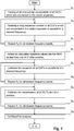
- Fig. 7 shows a flow chart diagram that describes the proceeding for testing several DUTs with the switch-extender 4 and the measurement system 1 according to the present invention.
- the procedural step S 1 is executed.
- all DUTs are powered up and the non-cellular components of all DUTs are tested.
- those components are connected to the third antenna of each DUT.
- Bluetooth services GPS services or WLAN services can be tested.
- the measurement system 1 transmits a downlink signal to all DUTs 7 1 to 7 4 and/or 12 1 to 12 4 simultaneously.
- the third antenna of each DUT is connected one after another with the measurement system 1 for measuring the uplink signal.
- the procedural step S 2 is executed.
- the procedural step S 2 is preferably executed when the cellular components are booted.
- the cellular components comprise for example CDMA-chips. Those chips have a longer boot time than the non-cellular components.
- a downlink signal is sent from the measurement system 1 to all DUTs 7 1 to 7 4 and 12 1 to 12 4 which comprises a long data sequence. This sequence is well known and allows the DUTs to calculate the bit error rate for example. In order to obtain a good statistic, the sequence is transmitted over a longer period, for example 10 seconds.
- the procedural step S 3 is executed. Within the procedural step S 3 the procedural step S 2 is repeated for all desired frequency bands and/or for all desired signal levels. The DUTs further calculate the bit error rate.
- the measurement system 1 collects all calculated BER-values for one DUT after another. This is done by decoupling the uplink signal which is transmitted from the DUT by using the coupling-unit 58 1 to 58 4 and 87 1 to 87 4 . As already described each frontend 3, 9 can only receive one uplink signal at the same time. However, the time for collecting the calculated BER-values is much shorter than the time for sending the sequence to all DUTs. Therefore, it does not matter that all DUTs cannot transmit the uplink signal at the same time.
- the procedural step S 5 is executed.
- the reception for every DUT is calibrated in parallel or one after another for the desired frequency. This is done by using the method and the system which is described in the U.S. patent application US 2009/0209249 A1 which is hereby incorporated by reference.
- the time between the steps wherein the signal level is lowered has to be as long as the time it needs to adjust the attenuators and the amplifiers. 300 microseconds should be enough.
- the procedural step S 6 is executed. In the procedural Step S 6 , the step S 5 is repeated for all desired frequency bands.
- the procedural step S 7 is executed.
- all DUTs are calibrated one after another for their transmission behavior.
- the method and the system that are used therefore are also described in the U.S. patent application US 2009/0209249 A1 which is hereby incorporated by reference.
- Each frontend 3, 9 receives only one uplink signal at the same time. The uplink signal is thereby stepped down continuously. However, the time for each step has to be chosen in such a way that the switch-extender 4 has enough time to adjust the settings for the attenuators, the amplifiers and the switches. This is done for all DUTs one after another.
- the procedural step S 8 is executed. Within the procedural step S 8 the former step S 7 is repeated for all desired frequency bands.
- a Pass/Fail-analysis is performed within the procedural step S 9 .
- Fig. 8 shows a schematic diagram that describes how the measurement system 1, the switch-extender 4 and the cable connection 100 1 to 100 4 as well as the 3 dB attenuator 101 1 , 101 2 are calibrated.
- the calibration is done by using a calibration system 102.
- the calibration system comprises a first measurement unit 103 and a second measurement unit 105. Both measurement units 1, 5 are connected together for example by using a USB-connection. Other connection methods can also be used.
- the calibration system 102 further includes a signal splitter 104.
- the signal splitter 104 divides an input signal into two equal output signals.
- the first measurement unit 103 is able to measure and to analyze a downlink signal as well as to generate a known uplink signal.
- the measurement unit 103 can be of the same type as the measurement system 1.
- the second measurement unit 105 is able to measure the signal power. The measured values are then transmitted to the first measurement unit 1 by using the USB-connection.
- the DUT 7 1 to 7 4 and 12 1 to 12 4 is directly connected with the cable 100 1 to 100 4 , so that no 3 dB attenuator 101 1 , 101 2 is needed.
- a cable 100 1 to 100 4 for establishing the connection
- other signal connectors like wave guides for example can also be used.
- the object of the calibration is to determine the necessary settings within the measurement system 1 and the switch-extender 4 in order to generate a predefined signal level at the first or at the second or at the third antenna of the DUT. It has to be noted that all cables 100 1 to 100 4 as well as all connectors and the attenuators 101 1 , 101 2 which are used within the calibration also have to be used in the later measurement steps.
- Every output port of the switch-extender 4 has its own dedicated cable.
- the output ports of the MUX/DEMUX-unit 5 as well as of the second MUX/DEMUX-unit 6 are connected one after another with the calibration system 102.
- the same also applies to the further MUX/DEMUX-unit 10 as well as for the MUX/DEMUX-unit 11.
- Fig. 10 only describes the calibration method for the MUX/DEMUX-unit 5 within the switch-extender 4 having eight output ports.
- the first output port of the MUX/DEMUX-unit 5 which is labeled with "RF1" according to Fig. 3 is connected to a cable 100 1 .
- the other end of the cable 100 1 is connected to a 3 dB attenuator 101 1 .
- the attenuator 101 1 would normally be connected with the first antenna of the first DUT 7 1 .
- the other end of the attenuator 101 1 that is not connected to the cable 100 1 is thereby connected with the calibration system 102. More exactly, the attenuator 101 1 is connected with the input of the signal splitter 104 within the calibration system 102.
- the measurement system 1 In the first instance, the measurement system 1 generates a downlink signal which would normally be used to measure the proper functioning of the first antenna of the first DUT 7 1 .
- the measurement system 1 generates this downlink signal having a specific frequency as well as a specific signal level.
- the downlink signal is split within the signal splitter 104 into two equal signals. One signal is transmitted to the first measurement unit 103 whereas the other signal is transmitted to the second measurement unit 103. It has to be understood that the signal splitter 14 has to be well known when thinking of its attenuation or its diversity.
- the first measurement unit 103 and the second measurement unit 105 measure the downlink signal properties, for example the frequency as well as the signal at the input port of the signal splitter 104.
- This data is used in order to inform the measurement system 1 about the difference between the measured values of the downlink signal and the estimated values of the downlink signal. This information is then used within the measurement system 1 to generate calibration data in order to generate a downlink signal which has a predetermined frequency as well as a predetermined signal level at the antenna port of the DUT.
- the calibration data can also be generated the calibration system 102.
- the calibration data for the uplink signal has also to be generated.
- the uplink signal as well as the downlink signal should be similar to the real signal.
- the uplink signal is generated by the first measurement unit 103.
- the first measurement unit 103 outputs the uplink signal to the signal splitter 104.
- One output port of the signal splitter 104 is still connected to second measurement unit 105 which is also connected the first measurement unit 103 by using a standard connection for data transmission, like USB or the like.
- the other output port of the signal splitter 104 is still connected with the cable 100 1 over the 3 dB attenuator 101 1 . It is very advantageous that the cable connection has not to be changed for generating calibration data for the uplink signal.
- the second measurement unit 105 also measures the uplink signal generated by the first measurement unit 103 and makes sure that the uplink signal has the dedicated signal frequency as well as the dedicated signal level at the output port of the signal splitter 104.
- the uplink signal travels through the attenuator 101 1 and the cable 100 1 through the switch-extender 4 into the measurement system 1.
- the measurement system 1 measures the signal frequency as well as the signal level. Based on the difference between the measured uplink signal within the measurement system 1 and the measured uplink signal at the output port of the signal splitter 105, the calibration data is obtained by the calibration system 102 or by the measurement system 1. The calibration data takes into account the downlink signal path as well as the uplink signal path. The calibration data is obtained for several frequencies as well as for several signal levels. Based on the calibration data, the measurement system 1 as well as the switch-extender 4 know how to set the attenuators, the amplifiers as shown in Fig. 3 or Fig. 4 in detail.
- the second cable 100 2 together with the second attenuator 101 2 is connected to the input port of the signal splitter 104 of the calibration system 102. Then the calibration data is obtained for the second cable 100 2 as well as the attenuator 101 2 . This is done for the downlink signal as well as for the uplink signal as described above for a specific frequency as well for a specific signal level.
- Fig. 9 shows a flow chat diagram of a calibration routine according to the present invention.
- the calibration routine has already been described to a certain extent.
- a procedural step S 10 the connections between the switch-extender 4 and the calibration system 102 are established. Those connections can be established by using a signal connector 100 1 to 100 4 like a cable 100 1 to 100 4 or a wave guide or the like.
- the signal connector 100 1 to 100 4 can be connected directly to the calibration system 102 or through an attenuator 101 1 , 101 2 like a 3 dB attenuator.
- step S 11 a signal with a specific signal level and/or a specific signal frequency is generated and output by the measurement system 1 for testing the downlink path. Since the measurement system 1 is connected through the switch-extender 4 and the signal connector 100 1 to 100 4 to the calibration system 102, the output signal can be measured by the calibration system 102.
- the calibration system 102 measures the signal level and/or the signal frequency at the output of the signal connector 100 1 to 100 4 or at the output of the attenuator 101 1 , 101 2 if used.
- the procedural step S 13 is executed.
- a difference between the measured signal level and/or the measured signal frequency and the generated signal with the specific signal level and/or the specific signal frequency is determined. It is known by the calibration system 102 what signal level and/or signal frequency should be obtained so that a deviation can be calculated.
- calibration data are calculated by using the determined difference between the measured signal level and/or the measured signal frequency and the generated signal with the specific signal level and/or the specific signal frequency. This can be done by the calibration system 102 or even by the measurement system 1.
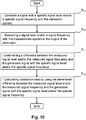
- Fig. 10 shows a flow chat diagram of a calibration routine according to the present invention.
- the calibration routine has already been described to a certain extent.
- step S 15 is executed. It has to be noted that the measurement system 1 and the switch-extender 4 are still connected to each other and to the calibration system 102. In this step a signal with a specific signal level and/or a specific signal frequency is generated and output by the calibration system 102 for testing the uplink path. Since the measurement system 1 is connected through the switch-extender 4 and the signal connector 100 1 to 100 4 to the calibration system 102, the output signal can be measured by the measurement system 1. The calibration system 102 can also still measure the generated signal by itself using the second measurement unit 105.
- the measurement system 1 measures the signal level and/or the signal frequency at the output of the signal connector 100 1 to 100 4 or at the output of the attenuator 101 1 , 101 2 if used.
- the procedural step S 17 is executed.
- a difference between the measured signal level and/or the measured signal frequency and the generated signal with the specific signal level and/or the specific signal frequency is determined. It is known by the measurement system 1 what signal level and/or signal frequency should be obtained so that a deviation can be calculated.
- calibration data are calculated by using the determined difference between the measured signal level and/or the measured signal frequency and the generated signal with the specific signal level and/or the specific signal frequency. This can be done by the calibration system 102 or even by the measurement system 1.
- Fig. 11 shows another flow chat diagram of a further calibration routine according to the present invention.
- the switch-extender 4 further comprises at least one attenuator 36 1 , 36 2 , 36 3 , 36 4 , 36 5 , 36 6 , 36 7 , 36 8 or the at least one attenuator 36 1 , 36 2 , 36 3 , 36 4 , 36 5 , 36 6 , 36 7 , 36 8 and a second attenuator 37 1 , 37 2 , 37 3 , 37 4 , 37 5 , 37 6 , 37 7 , 37 8 in a row for every output port a signal connector 100 1 to 100 4 is connected to the switch-extender 4.
- a procedural step S 18 can be executed.
- the attenuation factor of the at least one attenuator 36 1 to 36 8 or adjusting the attenuation factor of the at least one attenuator 36 1 to 36 8 and the second attenuator 37 1 to 37 8 can be adjusted so that the measured signal level and/or signal frequency of the signal is equal to the generated signal with the specific signal level and/or the specific signal frequency.
- the procedural step S 18 and the procedural steps S 12 , S 13 and S 16 , S 17 are executed alternately until the difference is smaller than a predefined threshold.
- Fig. 12 shows another flow chart diagram of a further calibration routine according to the present invention.
- a procedural step S 20 describes the previous steps are repeated for every desired frequency and/or signal level.
- the step S 20 repeats the steps Generating, Measuring, Determining and Calculating for another signal frequency and/or signal level or Repeating the steps Generating, Measuring, Determining, Adjusting and Calculating for another signal frequency and/or signal level as described above.
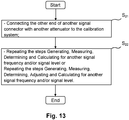
- Fig. 13 shows another flow chart diagram of a further calibration routine according to the present invention.
- the procedural steps S 21 and S 22 describe that after the calibration of one signal connector 100 1 to 100 4 and the corresponding signal path for the downlink and the uplink within the switch-extender 4 and optional for the attenuator 101 1 , 101 2 another signal connector 100 1 to 100 4 is connected at another output port of the switch-extender 4.
- the procedural steps S 22 describes that the former steps Generating, Measuring, Determining and Calculating are repeated for another signal frequency and/or signal level or that the former steps Generating, Measuring, Determining, Adjusting and Calculating are repeated for another signal frequency and/or signal level.
- the transmission path as well as the receiving path comprise active components like attenuators or amplifiers which are built using transistors and/or discrete elements like diodes for example or the like to compensate the loss in the signal levels. Furthermore, it is very important that those components have very fast switching times so that the actual settings can be adjusted very fast. This reduces the needed measurement time. This also allows that the signal level as well the signal frequency can be switched very fast, since the correction of the attenuator as well as the amplifiers takes place in nearly no time.
- switch-extenders are connected to the switch-extender 4 in order to obtain a measurement system 1 that allows measuring more than eight DUTs having two antennas used in parallel for cellular applications.
- the specific arrangement shown above is not limited to a measurement system 1 and a switch-extender 4 used for only four DUTs. All features shown above can be combined together in any order.
Landscapes
- Engineering & Computer Science (AREA)
- Physics & Mathematics (AREA)
- General Physics & Mathematics (AREA)
- Computer Networks & Wireless Communication (AREA)
- Signal Processing (AREA)
- Power Engineering (AREA)
- Computer Hardware Design (AREA)
- Microelectronics & Electronic Packaging (AREA)
- General Engineering & Computer Science (AREA)
- Monitoring And Testing Of Transmission In General (AREA)
- Tests Of Electronic Circuits (AREA)
- Testing Electric Properties And Detecting Electric Faults (AREA)
Abstract
Description
- The present invention relates to a switch-extender and a method for calibrating a measurement system with such a switch-extender, especially for testing mobile communication systems, for example mobile phones, handhelds, tablet PCs and WLAN-routers.
- Due to the increasing number of mobile communication systems, for example mobile phones, there is a strong demand in reducing the overall test time. As the complexity of mobile communication systems increases from generation to generation, the required test time also increases. Therefore, it is very difficult to reduce the test time for each mobile communication system. Therefore, the approach of the present invention is that the overall test time can be reduced significantly by testing several mobile communication systems, like mobile phones, in parallel.
- Document
US 2005/0264373 A1 describes a switching matrix that allows connecting multiple input ports to multiple output ports as well as to power sources. It is disadvantageous that documentUS 2005/0264373 A1 does not allow compensating different signal behavior in different signal path. Therefore, an input signal which is output at several ports has a different signal level which makes a switching matrix unsuitable for supplying a plurality of mobile communication systems in parallel with a test signal. - Therefore, it is the object of the present invention to create a switch-extender and a respective calibration method that allows connecting one input port to several output ports at the same time and that ensures that the signal level at every output port can be adjusted separately.
- This object is solved by the
independent claim 1 relating to a switch-extender and by theindependent claim 13 relating to a method for calibrating a measurement system. Any beneficial further developments of the invention are defined in the dependent claims. - The inventive switch-extender has at least one input port and several output ports, wherein the at least one input port and the several output ports are connected to a first Multiplexer/Demultiplexer-means (in the following MUX/DEMUX-means or -unit) wherein the first MUX/DEMUX-means connects the at least one input port to all output ports, wherein the MUX/DEMUX-means comprises at least one amplifier for amplifying a signal at the at least one input port and/or wherein the MUX/DEMUX-means comprises at least one attenuator for each of the output ports for attenuating a signal at every output port.
- It is very advantageous that at least one amplifier is connected to the at least one input port and/or the at least one attenuator is connected to each of the output ports. Therefore, a signal, which is split to different output-ports can be amplified to a certain signal level and then attenuated by an individual attenuation factor (attenuation value) to compensate for the individual signal path to obtain output signals having a predetermined signal level. This allows that every DUT that is connected with the switch-extender receives a test signal having exact the predetermined signal level which makes the whole test procedure meaningful and allows to compare the DUTs (devices under test) to each other.
- The inventive method is used for calibrating a measurement system comprising a measurement unit, a switch-extender connected to the measurement unit and several signal connectors having one end connected to the switch-extender and several attenuators connected to an other end of the several signal connectors and one calibration system wherein a sequence of procedural steps are executed. First of all the other end of one signal connector is connected with an attenuator to the calibration system. Then a signal is generated with a specific signal level and/or a specific signal frequency with the measurement unit. After that a signal level and/or a signal frequency is measured with the calibration system at the output of the attenuator. In the following a difference between the measured signal level and/or the measured signal frequency and the generated signal with the specific signal level and/or the specific signal frequency is determined. Finally calibration data are calculated by using the determined difference between the measured signal level and/or the measured signal frequency and the generated signal with the specific signal level and/or the specific signal frequency.
- It is advantageous that the signal connectors are used which are later also used for the measurement of the DUTs. This means that the determined difference and the calculated calibration data can be used later.
- It is also advantageous if a second attenuator is connected in series with the at least one attenuator and if the at least one attenuator has a larger attenuation range and higher attenuation steps than the second attenuator. This allows that the at least one attenuator is used as a coarse attenuator having a wide attenuation range and that the second attenuator can be used for a fine attenuation thereby allowing to adjust the attenuation factor (attenuation value defining the attenuation level) over a wide range accurately.
- It is further beneficial if a coupling-unit is connected between the least one attenuator or the second attenuator and the corresponding output port and if the coupling-unit has a third port at which a signal is transmitted that is input in the corresponding output port. This allows that the output port can be used as bidirectional port for the reflected and/or transmitted signal which is input thereto as well.
- It is also advantageous if at least one input port and several output ports are connected to a second MUX/DEMUX-unit wherein the second MUX/DEMUX-unit comprises the same elements as the first MUX/DEMUX-unit with the difference that the at least one input port is connected to a switch and if one output port of the switch is connected to an input port of an amplifier and if an other output port of the switch is connected to an output port of another amplifier so that the at least one input port acts as bidirectional port. This allows that the only input port of the second MUX/DEMUX-unit that is connected to the measurement unit can be used as a bidirectional port. A DUT connected to the output port of the second MUX/DEMUX-unit can therefore transmit a signal to the second MUX/DEMUX-unit that will be forwarded to the measurement unit.
- However, another advantage exists if the switch-extender comprises a plurality of first MUX/DEMUX-units and a plurality of second MUX/DEMUX-units wherein the input ports of the plurality of second MUX/DEMUX-units are connected to an input port of a multiplexer, wherein the output port of each multiplexer is connected to at least one amplifier of each of the plurality of the second MUX/DEMUX-units and wherein the output ports of each multiplexer are connected to the output of another amplifier of each of the plurality of the second MUX/DEMUX-units. This allows that every second MUX/DEMUX-unit can multiply the number of output ports addressable by the individual MUX/DEMUX-unit by the number of other MUX/DEMUX-units. Therefore, DUTs having more antennas can be tested without difficulties.
- Last but not least it is also very advantageous if the switch-extender further comprises a processing unit and a storage unit connected to each other wherein the processing unit controls the amplification settings of the at least one amplifier and wherein the processing unit also controls the attenuation settings of the at least one attenuator so that the signal has at every output port a predetermined signal level for every frequency. This ensures that the switching times are reduced to a minimum, so that changes in the signal level resulting from changes in the frequency of operation can be compensated fast.
- It is also very advantageous that the method for calibrating a measurement system includes the switch-extender that further comprises at least one attenuator or at least one attenuator and a second attenuator in series for every output port and that the attenuation factor of the at least one attenuator is adjusted or that the attenuation factor of the at least one attenuator and the second attenuator is adjusted, so that the measured signal level and/or signal frequency of the signal is equal to the generated signal with the specific signal level and/or the specific signal frequency. This ensures that despite one input signal being split into several output signals, every output signals has the same signal level.
- Different embodiments of the present invention are described exemplary in the following in reference to the description. This is done by the way of example without limitation. The same subject matter has the same reference signs. The figures in the drawings show in detail:
- Fig. 1
- a measurement system, a switch-extender and several DUTs according to an embodiment of the present invention;
- Fig. 2
- a measurement system, another switch-extender and several DUTs according to an embodiment of the present invention;
- Fig. 3
- a detailed configuration of the plurality of first MUX/DEMUX-units according to an embodiment of the present invention;
- Fig. 4
- a detailed configuration of the plurality of second MUX/DEMUX-units according to an embodiment of the present invention;
- Fig. 5
- a 3-dimensional view of the exemplary embodiment of the switch-
extender 4 according to the present invention; - Fig. 6
- another detailed configuration of the plurality of second MUX/DEMUX-units sharing the output ports of each other according to an embodiment of the present invention;
- Fig. 7
- a flow chart diagram of a test routine according to an embodiment of the present invention;
- Fig. 8
- a measurement system, a switch-extender and a calibration system according to an embodiment of the present invention;
- Fig. 9
- a flow chart diagram of a calibration routine according to an embodiment of the present invention;
- Fig. 10
- another flow chat diagram of a further calibration routine according to an embodiment of the present invention;
- Fig. 11
- another flow chat diagram of a further calibration routine according to an embodiment of the present invention;
- Fig. 12
- another flow chat diagram of a further calibration routine according to an embodiment of the present invention; and
- Fig. 13
- another flow chat diagram of a further calibration routine according to an embodiment of the present invention.
- In the following some preferred embodiments of the present invention are described in detail.
-
Fig. 1 shows the basic principle of the present invention. It shows ameasurement system 1 which is used for generating a test signal (downlink signal) and which is also used for measuring a signal transmitted from the DUTs (uplink signal). Therefore, themeasurement system 1 comprises a TRX unit 2 (transmit receive) which is used for generating the base band and/or the RF (radio frequency). Furthermore themeasurement system 1 also comprises afrontend 3 which comprises a reference circuit and which divides the signal from or to theTRX unit 2 into three input or output ports. For example, there is a first port "RF1Out" which is used to output the test signal (downlink signal) that is normally a high frequency signal, like a GSM or UMTS (CDMA signal in generally). Furthermore, there is a second port "RF1COM" which is used to output the test signal (downlink signal) or which can be used as an input port for a signal (uplink signal) that is transmitted by the mobile communication system to be measured by themeasurement system 1. Furthermore, there is a third port "RF2COM" which can also be used to output the test signal (downlink signal) and which can also be used to input a signal (uplink signal) transmitted from the mobile communication system 7 (device under test - DUT). - However, all three ports "RF1Out", "RF1COM" and "RF2COM" are connected to a switch-
extender 4 according to the embodiment of the present invention. The switch-extender 4 comprises a first MUX/DEMUX-unit 5 having a ratio of one to eight. The switch-extender 4 according to the present invention may also have a second MUX/DEMUX-unit 6 which has a ratio of one to four. The second MUX/DEMUX-unit 6 is optional. However, other ratios are also possible. The switch-extender 4 will be described in the following in detail. - Furthermore, the switch-
extender 4 is preferably connected to severalmobile communication systems 7, also called devices under test (DUT). This connection is done by using a cable connection. In this case, there are four devices under test, also calledDUTs DUTs DUT Fig. 1 also shows that two antennas of eachDUT unit 5 of the switch-extender 4. Those antennas are used for communication by using the MIMO (Multiple Input, Multiple Output) technique. A third antenna of eachDUT unit 6. The third antenna can be used for GPS or WLAN. It can also be used for Bluetooth or other communication standards. - The antennas of the
DUT Fig. 1 . Using a 3 dB attenuator, the reflected wave from the antenna of the DUT has a signal level which is 6 dB lower than the signal level of the signal (downlink) which is transmitted from themeasurement system 1 over the switch-extender 4 to the antennas of theDUT - The second MUX/DEMUX-
unit 6 is only used for none-cellular applications like WLAN, Bluetooth or GPS or the like. If the DUT uses only one antenna for cellular applications (none-MIMO) the switch-extender 4 can support up to eight DUTs. - If the second MUX/DEMUX-
unit 6 is used, the none-cellular applications (WLAN, Bluetooth and/or GPS) are tested first, since the cellular chips (CDMA-chips) need more time to come up. Themeasurement system 1 generates a base band-signal (downlink) in the TRX-unit 2. This signal (downlink) is then sent to the MUX/DEMUX-unit 6 using the third port "RF2COM" of the second MUX/DEMUX unit 6. The second MUX/DEMUX-unit 6 connects the third port of themeasurement system 1 to the third antenna of thefirst DUT 71. After the test signal is sent, thefirst DUT 71 is processing it. After thefirst DUT 71 has processed the test signal, it outputs the results, for example the current GPS-position using the third antenna or a data bus which is not shown. The second MUX/DEMUX-unit 6 still connects the third antenna to the third port "RF2COM" of themeasurement system 1. Themeasurement system 1 can analyze if the calculated results of thefirst DUT 71 are correct. If the none-cellular applications are tested for thefirst DUT 71, the second MUX/DEMUX-unit 6 connects the third port of thefrontend 3 of themeasurement system 1 to the third antenna of thesecond DUT 72. - The second MUX/DEMUX-
unit 6 connects allDUTs measurement system 1. The second MUX/DEMUX-unit 6 can also connect DUTs to another port of themeasurement system 1 as long as this port can also be used for transmitting and receiving signals. In this case, the second MUX/DEMUX-unit 6 can also be connected to the second port "RF1COM" of themeasurement system 1. - If the measurement of the none-cellular applications of the
DUTs DUTs measurement system 1 generates and transmits test signals to the first MUX/DEMUX-unit 5. The signals are generated in the TRX-unit 2 and are sent by using the first port "RF1OUT" of thefrontend 3. This test signal is then split into eight signals and transmitted to the first and to the second antenna of each of the fourDUTs DUTs unit 5 connects one DUT after another to the second port "RF1COM" of themeasurement system 1. Themeasurement system 1 then measures the uplink signal from each of theDUTs -
Fig. 2 shows ameasurement system 1 which comprises two separate TRX-units separate frontends extender 4 also comprises a first MUX/DEMUX-unit 5 and optionally a second MUX/DEMUX-unit 6 as described above. Furthermore, the switch-extender 4 comprises also a further MUX/DEMUX-unit 10 having also a ratio of one to eight and a MUX/DEMUX-unit 11 having a ratio of one to four. The MUX/DEMUX-unit 11 is also optional. Therefore, severalother DUTs unit 10 and to the MUX/DEMUX-unit 11 as described above referring to theDUTs -
Fig. 3 shows a detailed schematic diagram of the first MUX/DEMUX-unit 5 according to the present invention. It can be seen that the first MUX/DEMUX-unit 5 is divided into two parts. The first part is the transmission path and the second part is the receiving path. The transmission path is used to transmit a signal (downlink signal) frommeasurement system 1 to theDUTs 71 to 74 in parallel and the receiving path is used to transmit a signal (uplink signal) from theDUTs 71 to 74 to themeasurement system 1. The transmission path is connected to the first port "RF1Out" of thefrontend 3 of themeasurement system 1. - The downlink signal is split using a
signal splitter 30, like a Wilkinson divider, into two signals, both having preferably the same signal level. Each output port of thesignal splitter 30 is then connected to a switch 311, 312. One output port of each switch 311, 312 is not connected to anything, so the switch can be used to decouple the specific signal path at all. Normally the other output port of the switch 311, 312 is used to connect each output of thesignal splitter 30 to an amplifier 321, 322. The amplifiers 321, 322 can be used to amplify the signal by 0 to +20 dB. The output of each of the amplifiers 321, 322 is then connected to another signal splitter 331, 332. Each output port of the further signal splitters 331, 332 is then connected with another signal splitter 341, 342, 343, 344. The downlink signal which is generated by the TRX-Unit 2 is split up and amplified into eight equal signals. Those signals can be used for fourDUTs - However, before the eight individual downlink signals can be sent to the
DUTs level adjustment unit 35. Thelevel adjustment unit 35 is very important, because it comprises several attenuators. Each signal path that is used for carrying one of the split downlink signals comprises two attenuators arranged in series. Therefore, each output port of the further signal splitters 341, 342, 343, 344 is connected to a first attenuator 361, 362, 363, 364, 365, 366, 367 and 368. Those first attenuators 361 are 368 are also called step-attenuators. Those attenuators can be used to attenuate the split downlink signal in steps of approximately ¼ dB from 0 to 31 dB. The output port of each the first attenuators of each signal path is then connected to asecond attenuator - Each output port of the
level adjustment unit 35 or, to be more precise, each output port of the second attenuator is connected to one coupling-unit 381 to 388. The use of each coupling-unit is that the downlink signal which is split into up to eight individual downlink signals is transmitted to the first and to the second antenna of each DUT and that the uplink signal which is transmitted from the first and the second antenna of each DUT is transmitted back to the second output port "RF1COM" of themeasurement system 1. Therefore, the coupling-unit 381 to 388 prevents an uplink signal which is transmitted from the DUTs to travel across the downlink signal path. The coupling-unit 381 to 388 is preferably a directional coupling-unit 381 to 388, so that the uplink signal exits the directional coupling-unit 381 to 388 through another port. The directional coupling-unit 381 to 388 comprises three attenuators and three resistors, for example connected in a T-structure. Each output port RF1 to RF8 is connected to the first or to the second antenna of eachDUT extender 4 according to the present invention is that the downlink signal at the first and the second antenna of each of theDUTs level adjustment unit 35. Thelevel adjustment unit 35 allows a coarse and a fine tuning of the split downlink signals. Since the first and the second attenuator within thelevel adjustment unit 35 are built by using transistors or the like, the signal can be attenuated within 300 microseconds or less. Relays which are used in the state of the art are preferably not used within the present invention at all. - The signal level of the downlink signal is very low, for example -100 dBm. The third output ports RX1 to RX8 of each of the coupling-units 381 to 388 are connected to a multiplexer 391, 392. Each of the multiplexers 391, 392 have four input ports for example and one output port. Therefore, the uplink signal which is transmitted from the first and the
second DUT fourth DUT - The output port of each multiplexer 391, 392 is connected to another attenuator 401, 402. These attenuators 401, 402 are able to attenuate an uplink signal coarsely. In this example according to the present invention the attenuators 401, 402 can attenuate an uplink signal in steps of 0 dB, -13 dB and -26 dB. It is also possible to use an attenuator 401, 402 which attenuates an uplink signal in much smaller steps. If the
DUT - The output port of each of the attenuators 401, 402 is connected to an
amplifier amplifier measurement system 1 measures the uplink signal with the highest possible precision. - The output port of each amplifier is connected to a
switch 42. By using theswitch 42 and one of the multiplexer 391, 392 a control unit within the switch-extender 4 or within themeasurement system 1 selects the uplink signal from one antenna of one of oneDUT measurement system 1. The output port of theswitch 42 is then connected to the second port "RF1COM" of themeasurement system 1. It can also be connected to the third port "RF2COM" or to any port within themeasurement system 1 which allows inputting an uplink signal for further analyses. - However, the schematic diagram of
Fig. 3 can also be used within the further MUX/DEMUX-unit 10 as shown inFig. 2 . - The
level adjustment unit 35 selects an attenuation value for the first attenuators 361 to 368 and for thesecond attenuators 371 to 378 which is based on the individual cable and connectors as well as on the individual signal path. The correction data is obtained for each frequency point for each signal path as well as for each cable and connector. Therefore, if the frequency band for which the downlink signal is transmitted is changed, all attenuators within thelevel adjustment unit 35 have to be set for their new attenuation factor. - Furthermore, the
amplifiers level adjustment unit 35 as well as of the amplifiers 321, 322, as well as of theamplifiers - First of all, the aforementioned components can be connected to the
measurement system 1 directly. However, only very fast connection types are recommended. This could be done by an interface with a lot of parallel data lines applying a high clock rate. Themeasurement system 1 selects all attenuation factors as well as all amplifier factors for the selected frequency of operation of the downlink signal. This information can be extracted from calibration data which will be discussed below. SPI-commands allow those components to be programmed by themeasurement system 1. - A more preferred second possibility for adjusting the aforementioned components can be done by incorporating a
processing unit 45 within the switch-extender 4. The processing unit is connected to thelevel adjustment unit 35 and therein with the first attenuators and the second attenuators. Theprocessing unit 45 is further connected to theamplifier switches 311, 312, 42. Furthermore, the processing unit is also connected to themeasurement system 1. Themeasurement system 1 then signals theprocessing unit 45 the values of the attenuation and/or the amplification factors to be set and optional the position of the switches and the multiplexers. The communication itself between the processingunit 45 and the components within the switch-extender 4 is done without any knowledge of themeasurement system 1. For example, theprocessing unit 45 can communicate by using the SPI-commands on a single line or by using parallel data lines. - A third possibility is that the
processing unit 45 only receives the frequency and the signal level of the downlink signal which is transmitted by themeasurement system 1. Theprocessing unit 45 then alternates all attenuation factors or amplification factors by itself. Therefore, besides the processing unit 45 afurther storage unit 46 is needed where all calibration data are stored. This could be done by using a lookup-table comprising all attenuation factors and/or amplification factors needed for an individual signal level as well as for an individual signal frequency. Theprocessing unit 45 then reads out thestorage unit 46 and alternates those factors as required. - As shown in
Fig. 3 it is possible to transmit a downlink signal on eight signal paths in parallel. On the other hand, it is only possible to receive one uplink signal which is transmitted from one antenna of oneDUT switch 42 have to be changed. This can also be done by theprocessing unit 45 or by themeasurement system 1 directly. Therefore, the multiplexer 391, 392 as well as the switch have to be connected to theprocessing unit 45 and/or to themeasurement system 1. This can also be done by well known data connection types or by a parallel interface. The same also applies for the further MUX/DEMUX-unit 10. -
Fig. 4 shows a schematic diagram of the second MUX/DEMUX-unit 6 as well as of the MUX/DEMUX-unit 11 according to the present invention. As already described, the second MUX/DEMUX-unit 6 is used to measure the none-cellular applications within theDUT measurement system 1, in particular the TRX-unit 2 and thefrontend 3 generate a downlink signal which is output at the third output port "RF2COM". For the second TRX-unit 8 and thesecond frontend 9 the subject matter as explained in detail above stays the same. It only differs in the names used for the reference signs. As already said, the third port "RF2COM" can be used to output a downlink signal or to input an uplink signal. In the following the case where a downlink signal is transmitted to the third antenna of theDUT switch 50. One output port of theswitch 50 is connected to anotherswitch 51. One output of theswitch 51 is connected to anamplifier 52. Theamplifier 52 is used to amplify the downlink signal by 0 to +20 dB. The output of theamplifier 52 is connected to asignal splitter 53. Thesignal splitter 53 can be a Wilkinson divider. - Each output port of the
signal splitter 53 is connected to an input port of another signal splitter 541, 542. Each output port of the further signal splitters 541, 542 is connected to the secondlevel adjustment unit 55. The secondlevel adjustment unit 55 comprises the same structure as thelevel adjustment unit 35 as described inFig. 3 . In contrast to thelevel adjustment unit 35 as described inFig. 3 , the secondlevel adjustment unit 55 only comprises four signal paths. In each signal paths, there are two attenuators arranged in series. A first attenuator 561, 562, 563, 564 is used to attenuate the split downlink signal in a coarse step. For example, the first attenuator 561 to 564 can attenuate the split downlink signal in steps of 1-4 dB over a range from 0 to 31 dB. The output port of the first attenuator 561 to 564 is then connected to an input port of asecond attenuator second attenuators 571 to 574 can attenuate a signal in steps of 2 mdB or the like. The output port of thesecond attenuators 571 to 574 is then connected to a coupling-unit 581 to 584. The design of the coupling-unit 581 to 584 as shown inFig. 4 is the same as the design of the coupling-unit 381 to 388 as shown inFig. 3 so that a reference is made to the description above. The second output port RF1 to RF4 of the coupling-unit 581 to 584 is connected to the third antenna of theDUTs measurement system 1 generates and transmits a downlink signal to the third antenna of allDUTs level adjustment unit 55 makes sure that the level of the downlink signal is the same for all signal paths at the third antenna of eachDUT amplifier 52 and the first attenuator 561 to 564 and thesecond attenuator 571 to 574 properly. - The same also applies for every uplink signal. The uplink signal transmitted from the third antenna of each
DUT multiplexer 59. The multiplexer has four input ports connected to each of the coupling-units 581 to 584 and one output port connected to anattenuator 60. Theattenuator 60 attenuates the uplink signal in a coarse way. For example, an attenuation factor of 0, -13, -26 dB can be selected. However, also other attenuators can be used which allow the selection of an attenuation factor having finer steps. The output port of theattenuator 60 is then connected to the input port of anamplifier 61. Theamplifier 61 is then connected to the second "output" port of theswitch 50. Theswitch 50 then connects the output port of theamplifier 61 to the third port "RF2COM" of themeasurement system 1. Theattenuator 60 is thereby selected to attenuate a strong signal with a higher attenuation factor than a weak signal. For example, if the DUT transmits an uplink signal having asignal level 30 dB, theattenuator 60 attenuates this signal by -26 dB. On the other hand, if the DUT transmits a signal having a signal level of 0 dB, theattenuator 60 attenuates this signal with 0 dB. Other values are also possible. - As already described in
Fig. 3 theamplifiers measurement system 1 directly or by theprocessing unit 45. The same also applies for theswitch 50, theswitch 51 and themultiplexer 59. Theswitch 51 can be used to separate the transmitting path from the receiving path in order to increase the isolation between them. - As already explained, the components can be controlled by the
measurement system 1 directly. In this case, themeasurement system 1 sets all switch positions and/or all attenuation and/or amplification factors. On the other hand, themeasurement system 1 can signal theprocessing unit 45 the switching positions and the amplification and/or attenuation factors. The third possibility is that themeasurement system 1 only informs theprocessing unit 45 about the frequency and the signal level of the downlink signal and/or the number of the DUT which has to be measured in the uplink path. Theprocessing unit 45 then reads the settings from astorage unit 46 and makes the needed adjustments. - The same also applies for the MUX/DEMUX-
unit 11 as also shown inFig. 4 . For those components no reference signs are placed. However, all explanations made to the second MUX/DEMUX-unit 6 are also valid for the MUX/DEMUX-unit 11. -
Fig. 5 shows a 3-dimensional view of the exemplary embodiment of the switch-extender 4 according to the present invention. The switch-extender 4 comprises a series of input and/or output ports. The ports for connecting the switch-extender 4 to themeasurement system 1 are located on the right side of the switch-extender 4.Fig. 5 shows the ports "RF1Out", RF1COM" and "RF2COM" for connecting the switch-extender 4 to thefirst frontend 3 within themeasurement system 1. Furthermore,Fig. 5 also shows the ports "RF3Out", "RF3COM" and "RF4COM" for connecting the switch-extender 4 to thesecond frontend 9 within themeasurement system 1. In this exemplary embodiment, the ports for connecting the switch-extender 4 to themeasurement system 1 are shown on the right, but they can also be located anywhere on the front or the rear panel of the switch-extender 4. - The other ports are used for connecting the switch-
extender 4 to the series of antennas of theDUTs unit 5 as shown inFig. 3 . WithinFig. 3 these ports are named RF1 to RF8. The top row comprises the input and/or output ports for the further MUX/DEMUX-unit 10 which is connected to thesecond frontend 9. With respect toFig. 2 , also eight ports are used therefor. The row in the middle is used for the second MUX/DEMUX-unit 6 as well as for the MUX/DEMUX-unit 11. In this exemplary embodiment the four ports from left to right represent the output and/or input ports of the second MUX/DEMUX-unit 6, whereas the four ports following on the right represent the input and/or output ports of the MUX/DEMUX-unit 11. However, it is obvious that the input and/or output ports can be arranged in different ways. Beside every port, there are two LEDs 701, 702. Those LEDs 701, 702 indicate whether the individual port is used as an output port or an input port. - All ports are mounted directly on a printed circuit board. Preferably there are no cable connections. There is normally one printed circuit board for each row using connectors to connect the individual printed circuit boards together. All printed circuit boards are controlled by a
central processing unit 45. However, as described above, the ports can also be controlled by themeasurement system 1 itself. -
Fig. 6 shows a further exemplary embodiment of a schematic diagram according to the present invention. According toFig. 5 the output and/or input ports in the middle of the row are shared between thefirst frontend 3 and thesecond frontend 9. One possibility on how to connect these ports with themeasurement system 1 is shown inFig. 4 . As already described above, it is not possible for thefirst frontend 3 and for thesecond frontend 9 to use the output ports of the switch-extender 4 from each another. This means that thefirst frontend 3 can only address fourDUTs second frontend 9. Thesecond frontend 9 can also only address fourDUTs 121 to 124 each having one third antenna. However, some DUTs may have more than three antennas. Therefore, it would be desirable if thefirst frontend 3 could also use the output and/or input ports of the switch-extender 4 linked to thesecond frontend 9. -
Fig. 6 describes a possibility that allows thefirst frontend 3 to use the input and/or output ports of the second MUX/DEMUX-unit 6 as well as the input and/or output ports of the MUX/DEMUX-unit 11. On the other hand,Fig. 6 also shows the possibility for thesecond frontend 9 to use the input and/or output ports of the MUX/DEMUX-unit 11 as well as the input and/or output ports of the second MUX/DEMUX-unit 6. - As shown in
Fig. 6 , the port "RF2COM" is connected to amultiplexer 80 and the port "RF4COM" is connected to amultiplexer 81. It is noted that the ports "RF2COM" and "RF4COM" are bidirectional ports which can be used as output ports as well as input ports. Therefore, the wording "multiplexer" is always used instead of the wording "demultiplexer". One output port of themultiplexer 80 can be connected to the transmit path as shown inFig. 4 . The transmit path comprises anotherswitch 82 and the well-knowncircuit elements - A second output of the
multiplexer 80 can also be connected to the second transmit path which was only used inFig. 4 by thesecond frontend 9. The second output of themultiplexer 80 is therefore connected to aswitch 83 and in row to theswitch 83 to asignal splitter 84. One outfit of thesplitter 84 is connected to theswitch 82 and the other output of the signal splitter is connected to theswitch 85. The output of theswitch 85 is thereby connected to the second signal path. The circuit elements of the second signal path are the same as the circuit elements of the first signal path. - The same applies for the uplink signal, namely the signal which is transmitted from the third antenna of the
DUT DUT 121 to 124. As described inFig. 4 , coupling-units 581 to 584 are used to decouple the uplink signal transmitted by the third antenna of theDUT multiplexer 59. Themultiplexer 59 selects one uplink signal at the same time and forwards it to anattenuator 60. The output of theattenuator 60 is connected to anamplifier 61. This subject matter is also described with respect toFig. 4 . WithinFig. 6 the output of theamplifier 61 is connected to aswitch 86. The output of theswitch 86 is connected to themultiplexer 80. - The same also applies for the uplink path of the
DUTs 121 to 124. The uplink signal transmitted from theDUTs 121 to 124 is decoupled by the coupling-units 871 to 874. Those coupling-units are integrated within a switch-extender 4 in the MUX/DEMUX-unit 11. The uplink signal is then fed to amultiplexer 88. Themultiplexer 88 selects one uplink signal at the same time and forwards it to anotherattenuator 89. The output port of theattenuator 89 is then connected to anamplifier 90. The output of theamplifier 90 is further connected to switch 91. One output of theswitch 91 is also connected to themultiplexer 80. Themultiplexer 88 is the same multiplexer as themultiplexer 59. Theattenuator 89 is the same attenuator as theattenuator 60. Theamplifier 90 is the same amplifier as the amplifier 69. This also applies for coupling-units 871 to 874 with respect to the coupling-units 581 to 584. - The aforementioned structure allows the
first frontend 3 to address the third antenna of theDUTs 71 to 74 and 121 to 124. Thefirst frontend 3 can transmit a downlink signal to all third antenna ports of theDUTs 71, to 74 and 121 to 124 at the same time. However, the uplink signal from the third antenna of everyDUT first frontend 3 one after another. The same also applies for thesecond frontend 9. The bidirectional port "RF4COM" is connected to themultiplexer 81 as described above. The output ports of themultiplexer 81 are connected to theswitch 83 as well as to theswitch 85 as well as to theswitch 86 and to theswitch 91. Therefore, it is also possible for thesecond frontend 9 to address all third antenna ports of allDUTs 71 to 74 and 121 to 124. Thesecond frontend 9 can therefore transmit the downlink signal to allDUTs 71 to 74 and 121 and 124 at the same time. The uplink signal transmitted from each DUT at the third antenna board can be measured one after another by switching themultiplexer switches multiplexer 81 accordingly. - To sum it up, the above described structure of the switch-
extender 4 havingfurther multiplexers units 6 that are connected to every downlink path and to every uplink path used by the second MUX/DEMUX-units 6 allows the plurality of the second MUX/DEMUX-units - However, all components like the switches, the amplifiers, the attenuators, the multiplexers can be controlled directly by the
measurement system 1 or they can be controlled by aprocessing unit 45. The subject matter is described in detail above so that a reference is made thereto. -
Fig. 7 shows a flow chart diagram that describes the proceeding for testing several DUTs with the switch-extender 4 and themeasurement system 1 according to the present invention. After all DUTs are connected to the switch-extender 4, the procedural step S1 is executed. Within the step S1 all DUTs are powered up and the non-cellular components of all DUTs are tested. As described above, those components are connected to the third antenna of each DUT. For example, in the step S1 Bluetooth services, GPS services or WLAN services can be tested. As already explained in detail, it is also possible that themeasurement system 1 transmits a downlink signal to allDUTs 71 to 74 and/or 121 to 124 simultaneously. After that the third antenna of each DUT is connected one after another with themeasurement system 1 for measuring the uplink signal. - If the non-cellular components are tested, the procedural step S2 is executed. The procedural step S2 is preferably executed when the cellular components are booted. The cellular components comprise for example CDMA-chips. Those chips have a longer boot time than the non-cellular components. Within the procedural S2 a downlink signal is sent from the
measurement system 1 to allDUTs 71 to 74 and 121 to 124 which comprises a long data sequence. This sequence is well known and allows the DUTs to calculate the bit error rate for example. In order to obtain a good statistic, the sequence is transmitted over a longer period, for example 10 seconds. - After the bit error rate is calculated by all DUTs in parallel for a desired frequency and/or for desired signal level, the procedural step S3 is executed. Within the procedural step S3 the procedural step S2 is repeated for all desired frequency bands and/or for all desired signal levels. The DUTs further calculate the bit error rate.
- Afterwards the procedural step S4 is executed. Within the procedural step S4, the
measurement system 1 collects all calculated BER-values for one DUT after another. This is done by decoupling the uplink signal which is transmitted from the DUT by using the coupling-unit 581 to 584 and 871 to 874. As already described eachfrontend - In the following, the procedural step S5 is executed. Within the procedural step S5, the reception for every DUT is calibrated in parallel or one after another for the desired frequency. This is done by using the method and the system which is described in the U.S. patent application
US 2009/0209249 A1 which is hereby incorporated by reference. The time between the steps wherein the signal level is lowered has to be as long as the time it needs to adjust the attenuators and the amplifiers. 300 microseconds should be enough. Afterwards, the procedural step S6 is executed. In the procedural Step S6, the step S5 is repeated for all desired frequency bands. - After that, the procedural step S7 is executed. Within the procedural step S7 all DUTs are calibrated one after another for their transmission behavior. The method and the system that are used therefore are also described in the U.S. patent application
US 2009/0209249 A1 which is hereby incorporated by reference. Eachfrontend extender 4 has enough time to adjust the settings for the attenuators, the amplifiers and the switches. This is done for all DUTs one after another. - Afterwards, the procedural step S8 is executed. Within the procedural step S8 the former step S7 is repeated for all desired frequency bands.
- Last but not least, a Pass/Fail-analysis is performed within the procedural step S9.
- It has to be noted that procedural steps S1 to S9 need not to be executed in the described order. For example, it is also possible that the method is finished after the procedural step S1 or after the procedural step S3 or after the procedural step S8. The order can also be mixed.
Fig. 8 shows a schematic diagram that describes how themeasurement system 1, the switch-extender 4 and the cable connection 1001 to 1004 as well as the 3 dB attenuator 1011, 1012 are calibrated. The calibration is done by using acalibration system 102. The calibration system comprises afirst measurement unit 103 and asecond measurement unit 105. Bothmeasurement units calibration system 102 further includes asignal splitter 104. Thesignal splitter 104 divides an input signal into two equal output signals. Thefirst measurement unit 103 is able to measure and to analyze a downlink signal as well as to generate a known uplink signal. In fact, themeasurement unit 103 can be of the same type as themeasurement system 1. Thesecond measurement unit 105 is able to measure the signal power. The measured values are then transmitted to thefirst measurement unit 1 by using the USB-connection. However, it is also possible that theDUT 71 to 74 and 121 to 124 is directly connected with the cable 1001 to 1004, so that no 3 dB attenuator 1011, 1012 is needed. Furthermore instead of using a cable 1001 to 1004 for establishing the connection other signal connectors like wave guides for example can also be used. - In the following it is described how the calibration is done. The object of the calibration is to determine the necessary settings within the
measurement system 1 and the switch-extender 4 in order to generate a predefined signal level at the first or at the second or at the third antenna of the DUT. It has to be noted that all cables 1001 to 1004 as well as all connectors and the attenuators 1011, 1012 which are used within the calibration also have to be used in the later measurement steps. - Thus it is very important that every output port of the switch-
extender 4 has its own dedicated cable. The output ports of the MUX/DEMUX-unit 5 as well as of the second MUX/DEMUX-unit 6 are connected one after another with thecalibration system 102. The same also applies to the further MUX/DEMUX-unit 10 as well as for the MUX/DEMUX-unit 11.Fig. 10 only describes the calibration method for the MUX/DEMUX-unit 5 within the switch-extender 4 having eight output ports. The first output port of the MUX/DEMUX-unit 5 which is labeled with "RF1" according toFig. 3 is connected to a cable 1001. The other end of the cable 1001 is connected to a 3 dB attenuator 1011. The attenuator 1011 would normally be connected with the first antenna of thefirst DUT 71. In this case, the other end of the attenuator 1011 that is not connected to the cable 1001 is thereby connected with thecalibration system 102. More exactly, the attenuator 1011 is connected with the input of thesignal splitter 104 within thecalibration system 102. - In the first instance, the
measurement system 1 generates a downlink signal which would normally be used to measure the proper functioning of the first antenna of thefirst DUT 71. Themeasurement system 1 generates this downlink signal having a specific frequency as well as a specific signal level. The downlink signal is split within thesignal splitter 104 into two equal signals. One signal is transmitted to thefirst measurement unit 103 whereas the other signal is transmitted to thesecond measurement unit 103. It has to be understood that the signal splitter 14 has to be well known when thinking of its attenuation or its diversity. However, thefirst measurement unit 103 and thesecond measurement unit 105 measure the downlink signal properties, for example the frequency as well as the signal at the input port of thesignal splitter 104. This data is used in order to inform themeasurement system 1 about the difference between the measured values of the downlink signal and the estimated values of the downlink signal. This information is then used within themeasurement system 1 to generate calibration data in order to generate a downlink signal which has a predetermined frequency as well as a predetermined signal level at the antenna port of the DUT. The calibration data can also be generated thecalibration system 102. - After the
calibration system 102 has generated the calibration data for the downlink signal, the calibration data for the uplink signal has also to be generated. The uplink signal as well as the downlink signal should be similar to the real signal. The uplink signal is generated by thefirst measurement unit 103. Thefirst measurement unit 103 outputs the uplink signal to thesignal splitter 104. One output port of thesignal splitter 104 is still connected tosecond measurement unit 105 which is also connected thefirst measurement unit 103 by using a standard connection for data transmission, like USB or the like. The other output port of thesignal splitter 104 is still connected with the cable 1001 over the 3 dB attenuator 1011. It is very advantageous that the cable connection has not to be changed for generating calibration data for the uplink signal. Thesecond measurement unit 105 also measures the uplink signal generated by thefirst measurement unit 103 and makes sure that the uplink signal has the dedicated signal frequency as well as the dedicated signal level at the output port of thesignal splitter 104. The uplink signal travels through the attenuator 1011 and the cable 1001 through the switch-extender 4 into themeasurement system 1. - The
measurement system 1 measures the signal frequency as well as the signal level. Based on the difference between the measured uplink signal within themeasurement system 1 and the measured uplink signal at the output port of thesignal splitter 105, the calibration data is obtained by thecalibration system 102 or by themeasurement system 1. The calibration data takes into account the downlink signal path as well as the uplink signal path. The calibration data is obtained for several frequencies as well as for several signal levels. Based on the calibration data, themeasurement system 1 as well as the switch-extender 4 know how to set the attenuators, the amplifiers as shown inFig. 3 orFig. 4 in detail. After the first cable 1001 is calibrated together with the attenuator 1011 and all connectors, the second cable 1002 together with the second attenuator 1012 is connected to the input port of thesignal splitter 104 of thecalibration system 102. Then the calibration data is obtained for the second cable 1002 as well as the attenuator 1012. This is done for the downlink signal as well as for the uplink signal as described above for a specific frequency as well for a specific signal level. - The aforementioned steps are repeated for all cables 1001 to 1004 that are used for the MUX/DEMUX-
unit 5 as well as for the second MUX/DEMUX-unit 6 and for the further MUX/DEMUX-unit 10 as well as for the MUX/DEMUX-unit 11. -
Fig. 9 shows a flow chat diagram of a calibration routine according to the present invention. The calibration routine has already been described to a certain extent. In a procedural step S10 the connections between the switch-extender 4 and thecalibration system 102 are established. Those connections can be established by using a signal connector 1001 to 1004 like a cable 1001 to 1004 or a wave guide or the like. The signal connector 1001 to 1004 can be connected directly to thecalibration system 102 or through an attenuator 1011, 1012 like a 3 dB attenuator. - In the following the procedural step S11 is executed. In this step a signal with a specific signal level and/or a specific signal frequency is generated and output by the
measurement system 1 for testing the downlink path. Since themeasurement system 1 is connected through the switch-extender 4 and the signal connector 1001 to 1004 to thecalibration system 102, the output signal can be measured by thecalibration system 102. - This is done within the procedural step S12. The
calibration system 102 measures the signal level and/or the signal frequency at the output of the signal connector 1001 to 1004 or at the output of the attenuator 1011, 1012 if used. - In the following the procedural step S13 is executed. Within the procedural step S12 a difference between the measured signal level and/or the measured signal frequency and the generated signal with the specific signal level and/or the specific signal frequency is determined. It is known by the
calibration system 102 what signal level and/or signal frequency should be obtained so that a deviation can be calculated. - In the next procedural step S14 calibration data are calculated by using the determined difference between the measured signal level and/or the measured signal frequency and the generated signal with the specific signal level and/or the specific signal frequency. This can be done by the
calibration system 102 or even by themeasurement system 1. -
Fig. 10 shows a flow chat diagram of a calibration routine according to the present invention. The calibration routine has already been described to a certain extent. - In the following the procedural step S15 is executed. It has to be noted that the
measurement system 1 and the switch-extender 4 are still connected to each other and to thecalibration system 102. In this step a signal with a specific signal level and/or a specific signal frequency is generated and output by thecalibration system 102 for testing the uplink path. Since themeasurement system 1 is connected through the switch-extender 4 and the signal connector 1001 to 1004 to thecalibration system 102, the output signal can be measured by themeasurement system 1. Thecalibration system 102 can also still measure the generated signal by itself using thesecond measurement unit 105. - This is done within the procedural step S16. The
measurement system 1 measures the signal level and/or the signal frequency at the output of the signal connector 1001 to 1004 or at the output of the attenuator 1011, 1012 if used. - In the following the procedural step S17 is executed. Within the procedural step S17 a difference between the measured signal level and/or the measured signal frequency and the generated signal with the specific signal level and/or the specific signal frequency is determined. It is known by the
measurement system 1 what signal level and/or signal frequency should be obtained so that a deviation can be calculated. - In the next procedural step S18 calibration data are calculated by using the determined difference between the measured signal level and/or the measured signal frequency and the generated signal with the specific signal level and/or the specific signal frequency. This can be done by the
calibration system 102 or even by themeasurement system 1. -
Fig. 11 shows another flow chat diagram of a further calibration routine according to the present invention. The switch-extender 4 further comprises at least one attenuator 361, 362, 363, 364, 365, 366, 367, 368 or the at least one attenuator 361, 362, 363, 364, 365, 366, 367, 368 and asecond attenuator extender 4. Thus a procedural step S18 can be executed. Within this step the attenuation factor of the at least one attenuator 361 to 368 or adjusting the attenuation factor of the at least one attenuator 361 to 368 and thesecond attenuator 371 to 378 can be adjusted so that the measured signal level and/or signal frequency of the signal is equal to the generated signal with the specific signal level and/or the specific signal frequency. The procedural step S18 and the procedural steps S12, S13 and S16, S17 are executed alternately until the difference is smaller than a predefined threshold. -
Fig. 12 shows another flow chart diagram of a further calibration routine according to the present invention. A procedural step S20 describes the previous steps are repeated for every desired frequency and/or signal level. The step S20 repeats the steps Generating, Measuring, Determining and Calculating for another signal frequency and/or signal level or Repeating the steps Generating, Measuring, Determining, Adjusting and Calculating for another signal frequency and/or signal level as described above. -
Fig. 13 shows another flow chart diagram of a further calibration routine according to the present invention. The procedural steps S21 and S22 describe that after the calibration of one signal connector 1001 to 1004 and the corresponding signal path for the downlink and the uplink within the switch-extender 4 and optional for the attenuator 1011, 1012 another signal connector 1001 to 1004 is connected at another output port of the switch-extender 4. After that the procedural steps S22 describes that the former steps Generating, Measuring, Determining and Calculating are repeated for another signal frequency and/or signal level or that the former steps Generating, Measuring, Determining, Adjusting and Calculating are repeated for another signal frequency and/or signal level. - In general, it is very important that the transmission path as well as the receiving path comprise active components like attenuators or amplifiers which are built using transistors and/or discrete elements like diodes for example or the like to compensate the loss in the signal levels. Furthermore, it is very important that those components have very fast switching times so that the actual settings can be adjusted very fast. This reduces the needed measurement time. This also allows that the signal level as well the signal frequency can be switched very fast, since the correction of the attenuator as well as the amplifiers takes place in nearly no time.
- It is also possible that further switch-extenders are connected to the switch-
extender 4 in order to obtain ameasurement system 1 that allows measuring more than eight DUTs having two antennas used in parallel for cellular applications. However, the specific arrangement shown above is not limited to ameasurement system 1 and a switch-extender 4 used for only four DUTs. All features shown above can be combined together in any order.
Claims (17)
- A switch-extender (4) having at least one input port and several output ports wherein the at least one input port and the several output ports are connected to a first multiplex/demultiplex means (5), wherein the first multiplex/demultiplex means (5) connects the at least one input port to the output ports,
characterized in that,
the multiplex/demultiplex means (5) comprises at least one amplifier (321, 322) for amplifying a signal at the at least one input port and/or that the multiplex/demultiplex means (5) comprises at least one attenuator (361, 362, 363, 364, 365, 366, 367, 368) for each of the output ports for attenuating a signal at every output port. - A switch-extender according to claim 1,
characterized in that,
the multiplex/demultiplex means (5) comprises at least one signal splitter (30) splitting the signal at the at least one input port into at least two signals. - A switch-extender according to claim 2,
characterized in that,
the multiplex/demultiplex means (5) comprises several other signal splitters (331, 332, 341, 342, 343, 344) having a first plurality of them (311, 312) connected directly or indirectly to the at least one signal splitter (30) and/or having a second plurality of them (341, 342, 343, 344) connected directly or indirectly to the first plurality of signal splitters (311, 312). - A switch-extender according to claim 2 or claim 3, characterized in that,
the at least one amplifier (321, 322) is connected to an input of the least one signal splitter (30) and/or
that the at least one amplifier (321, 322) is connected to every output of the at least one signal splitter (30) and/or
that the at least one amplifier (321, 322) is connected to every output of the at least first plurality of signal splitters (311, 312) and/or
that the at least one amplifier (321, 322) is connected to every output of the at least second plurality of signal splitters (341, 342, 343, 344). - A switch-extender according to any of the claims 2 to claim 4,
characterized in that,
the at least one attenuator (361, 362, 363, 364, 365, 366, 367, 368) is connected with every output of the at least one signal splitter (30) and/or
that the at least one attenuator (361, 362, 363, 364, 365, 366, 367, 368) is connected with every output of the at least first plurality of signal splitters (311, 312) and/or
that the at least one attenuator (361, 362, 363, 364, 365, 366, 367, 368) is connected with every output of the at least second plurality of signal splitters (341, 342, 343, 344). - A switch-extender according to any of the claims 2 to claim 5,
characterized in that,
the a second attenuator (371, 372, 373, 374, 375, 376, 377, 378) is connected in series with the at least one attenuator (361, 362, 363, 364, 365, 366, 367, 368) and that the at least one attenuator (361, 362, 363, 364, 365, 366, 367, 368) has a larger attenuation range and higher attenuation steps than the second attenuator (371, 372, 373, 374, 375, 376, 377, 378). - A switch-extender according to any of the preceding claims,
characterized in that,
a coupling-unit (381, 382, 383, 384, 385, 386, 387, 388) is connected between the least one attenuator (361, 362, 363, 364, 365, 366, 367, 368) or the second attenuator (371, 372, 373, 374, 375, 376, 377, 378) and the corresponding output port and
that the coupling-unit (381, 382, 383, 384, 385, 386, 387, 388) has a third port at which a signal is transmitted which is input in the corresponding output port. - A switch-extender according to claim 7,
characterized in that,
the third port of each coupling-unit (381, 382, 383, 384, 385, 386, 387, 388) is connected to an input port of one of at least one multiplexers (391, 392) and
that the output port of the at least one multiplexer (391, 392) is connected to an attenuator (401, 402) and that the attenuator (401, 402) is connected to an amplifier (411, 412) and that each amplifier (411, 412) is connected to an input port of a switch (42) and the output port of the switch (42) is connected to another output port of the switch-extender (4). - A switch-extender according to any of the preceding claims,
characterized in that,
at least one input port and several output ports are connected to a second multiplex/demultiplex means (6) wherein the second multiplex/demultiplex means (6) comprises the same elements as the first multiplex/demultiplex means (5) with the difference that the at least one input port is connected to a switch (50) and that one output port of the switch (50) is connected to an input port of an amplifier (51) and that an other output port of the switch is connected to an output port of another amplifier (61) so that the at least one input port acts as bidirectional port. - A switch-extender according to any of the preceding claims,
characterized in that,
the switch-extender (4) comprises a plurality of first multiplex/demultiplex means (5, 10) and a plurality of second multiplex/demultiplex means (6, 11) wherein the input ports of the plurality of second multiplex/demultiplex means (6, 11) are connected to an input port of a multiplexer (80, 81), wherein the output port of each multiplexer (80, 81) is connected to at least one amplifier (51; 52) of each of the plurality of the second multiplex/demultiplex means (6, 11) and wherein the output ports of each multiplexer (80, 81) are connected to the output of another amplifier (61, 90) of each of the plurality of the second multiplex/demultiplex means (6, 11). - A switch-extender according to any of the preceding claims,
characterized in that,
the switch-extender (4) further comprises a processing unit (45) and a storage unit (46) connected to each other wherein the processing unit (45) controls the amplification settings of the at least one amplifier (321, 322) and wherein the processing unit (45) controls the attenuation settings of the at least one attenuator (361, 362, 363, 364, 365, 366, 367, 368) in such a manner that the signal at every output port has a predetermined signal level for every frequency. - A switch-extender according to any of the preceding claims,
characterized in that,
a signal level of every signal at each of the several output ports can be adjusted individually by the at least one amplifier (321, 322) and/or the at least one attenuator (361, 362, 363, 364, 365, 366, 367, 368). - A method for calibrating a measurement system comprising a measurement unit (1), a switch-extender (4) connected to the measurement unit (1) and several signal connectors (1001 to 1004) having one end connected to the switch-extender (4) and several attenuators (1011, 1012) each connected to an other end of the several signal connectors (1001 to 1004) and one calibration system (102) wherein the following procedural steps are executed:- Connecting (S10) the other end of one signal connectors (1001 to 1004) with an attenuator (1011, 1012) to the calibration system (102);- Generating (S11) a signal with a specific signal level and/or a specific signal frequency with the measurement unit (1);- Measuring (S12) a signal level and/or a signal frequency with the calibration system (102) at the output of the attenuator (1011, 1012);- Determining (S13) a difference between the measured signal level and/or the measured signal frequency and the generated signal with the specific signal level and/or the specific signal frequency;- Calculating (S14) calibration data by using the determined difference between the measured signal level and/or the measured signal frequency and the generated signal with the specific signal level and/or the specific signal frequency.
- Method according to claim 13,
characterized by,
the following procedural steps:- Generating (S15) a signal with a specific signal level and/or a specific signal frequency with the calibration system (102);- Measuring (S16) a signal level and/or a signal frequency with the measurement system (1);- Determining (S17) a difference between the measured signal level and/or the measured signal frequency and the generated signal with the specific signal level and/or the specific signal frequency;- Calculating (S18) calibration data by using the determined difference between the measured signal level and/or the measured signal frequency and the generated signal with the specific signal level and/or the specific signal frequency. - Method according to claim 13 or claim 14,
characterized in that
the switch-extender (4) further comprises at least one attenuator (361, 362, 363, 364, 365, 366, 367, 368) or the at least one first attenuator (361, 362, 363, 364, 365, 366, 367, 368) and a second attenuator (371, 372, 373, 374, 375, 376, 377, 378) in series and for every output port a signal connector (1001 to 1004) is connected to the switch-extender (4) and that the following procedural step is executed:- Adjusting (S19) the attenuation value of the at least one attenuator (361, 362, 363, 364, 365, 366, 367, 368) or adjusting the attenuation value of the at least one first attenuator (361, 362, 363, 364, 365, 366, 367, 368) and the second attenuator (371, 372, 373, 374, 375, 376, 377, 378) so that the measured signal level and/or signal frequency of the signal is equal to the generated signal with the specific signal level and/or the specific signal frequency. - Method according to any of the claims 13 to 15, characterized by,
the following procedural step:- Repeating (S20) the steps Generating (S11, S15), Measuring (S12, S16), Determining (S13, S17) and Calculating (S14, S18) for another signal frequency and/or signal level or
Repeating (S20) the steps Generating (S11, S15), Measuring (S12, S16), Determining (S13, S17), Adjusting (S19) and Calculating (S14, S18) for another signal frequency and/or signal level. - Method according to any of the claims 13 to 16, characterized in that,
a signal connector (1001 to 1004) is a cable and that the following procedural steps are executed:- Connecting (S21) the other end of another signal connector (1001 to 1004) with another attenuator (1011, 1012) to the calibration system (102);- Repeating (S22) the steps Generating (S11, S15), Measuring (S12, S16), Determining (S13, S17) and Calculating (S14, S18) for another signal frequency and/or signal level or
Repeating (S22) the steps Generating (S11, S15), Measuring (S12, S16), Determining (S13, S17), Adjusting (S19) and Calculating (S14, S18) for another signal frequency and/or signal level.
Priority Applications (2)
| Application Number | Priority Date | Filing Date | Title |
|---|---|---|---|
| US13/657,419 US9357408B2 (en) | 2011-12-12 | 2012-10-22 | Switch-extender and a method for calibrating |
| US15/148,026 US10171266B2 (en) | 2011-12-12 | 2016-05-06 | Switch-extender and a method for calibrating |
Applications Claiming Priority (1)
| Application Number | Priority Date | Filing Date | Title |
|---|---|---|---|
| US201161569352P | 2011-12-12 | 2011-12-12 |
Publications (4)
| Publication Number | Publication Date |
|---|---|
| EP2605027A2 true EP2605027A2 (en) | 2013-06-19 |
| EP2605027A3 EP2605027A3 (en) | 2017-10-25 |
| EP2605027B1 EP2605027B1 (en) | 2023-10-25 |
| EP2605027B8 EP2605027B8 (en) | 2023-12-06 |
Family
ID=45819063
Family Applications (1)
| Application Number | Title | Priority Date | Filing Date |
|---|---|---|---|
| EP12158439.5A Active EP2605027B8 (en) | 2011-12-12 | 2012-03-07 | A switch-extender and a method for calibrating |
Country Status (2)
| Country | Link |
|---|---|
| US (2) | US9357408B2 (en) |
| EP (1) | EP2605027B8 (en) |
Cited By (2)
| Publication number | Priority date | Publication date | Assignee | Title |
|---|---|---|---|---|
| WO2015011255A1 (en) * | 2013-07-25 | 2015-01-29 | Rohde & Schwarz Gmbh & Co. Kg | Measuring instrument and measuring method for measuring mobile radios |
| US9949154B2 (en) | 2015-09-30 | 2018-04-17 | Rohde & Schwarz Gmbh & Co. Kg | Test system and method for testing multiple devices under test simultaneously |
Families Citing this family (7)
| Publication number | Priority date | Publication date | Assignee | Title |
|---|---|---|---|---|
| US10063329B2 (en) * | 2015-03-02 | 2018-08-28 | Rohde & Schwarz Asia Pte. Ltd | Measuring device and measuring method using broadcast measuring signals |
| US20160277158A1 (en) * | 2015-03-16 | 2016-09-22 | Terry Brown | Data communications troubleshooting device |
| US10429493B2 (en) * | 2015-05-12 | 2019-10-01 | Texas Instruments Incorporated | Socket device adapted to send, receive, and loopback test signals |
| CN107294565B (en) * | 2017-08-22 | 2020-11-17 | 广东电网有限责任公司电力科学研究院 | Wiring device of simulation test system |
| CN112305398A (en) * | 2019-08-01 | 2021-02-02 | 富港电子(东莞)有限公司 | Automatic circuit board testing system and method thereof |
| US11646807B2 (en) * | 2019-08-21 | 2023-05-09 | Commscope Technologies Llc | Methods including detecting cables connected to ports of communications network equipment and related systems |
| JP7379398B2 (en) * | 2021-02-16 | 2023-11-14 | アンリツ株式会社 | Signal generator and its attenuation correction method |
Citations (2)
| Publication number | Priority date | Publication date | Assignee | Title |
|---|---|---|---|---|
| US20050264373A1 (en) | 2004-05-26 | 2005-12-01 | Agilent Technologies, Inc | Switching matrix and method for distinction of a connecting line |
| US20090209249A1 (en) | 2004-09-29 | 2009-08-20 | Rohde & Schwarz Gmbh & Co. Kg | Method and System for Transmission and/or Reception Calibration of Mobile-Telephone Devices |
Family Cites Families (16)
| Publication number | Priority date | Publication date | Assignee | Title |
|---|---|---|---|---|
| US5412414A (en) * | 1988-04-08 | 1995-05-02 | Martin Marietta Corporation | Self monitoring/calibrating phased array radar and an interchangeable, adjustable transmit/receive sub-assembly |
| US5256964A (en) * | 1992-07-31 | 1993-10-26 | International Business Machines Corporation | Tester calibration verification device |
| SE509434C2 (en) * | 1997-05-16 | 1999-01-25 | Ericsson Telefon Ab L M | Antenna calibration device and method |
| US6041216A (en) * | 1998-01-07 | 2000-03-21 | Tunnel Radio Of America, Inc. | Radio communication system for use in tunnels |
| US6472940B1 (en) * | 1999-11-11 | 2002-10-29 | Broadcom Corporation | Gigabit ethernet transceiver with analog front end |
| US6515276B2 (en) * | 2001-03-17 | 2003-02-04 | Agilent Technologies, Inc. | Heterodyne optical spectrum analyzer with provisions for intensity noise subtraction |
| TW569536B (en) * | 2001-09-05 | 2004-01-01 | Elantec Semiconductor Inc | Analog demultiplexer |
| US6784731B2 (en) * | 2002-05-08 | 2004-08-31 | Lucent Technologies Inc. | System and method for reducing amplifier distortion using distortion feedback |
| US6766262B2 (en) * | 2002-05-29 | 2004-07-20 | Anritsu Company | Methods for determining corrected intermodulation distortion (IMD) product measurements for a device under test (DUT) |
| DE102004005130B3 (en) * | 2004-02-02 | 2005-04-14 | Infineon Technologies Ag | Transceiver unit for digital communications with calibration of transmission and reception paths for reducing output signal non-linearity |
| EP1791278A1 (en) * | 2005-11-29 | 2007-05-30 | Interuniversitair Microelektronica Centrum (IMEC) | Device and method for calibrating MIMO systems |
| GB0624584D0 (en) * | 2006-12-08 | 2007-01-17 | Medical Device Innovations Ltd | Skin treatment apparatus and method |
| US8242796B2 (en) * | 2008-02-21 | 2012-08-14 | Advantest (Singapore) Pte Ltd | Transmit/receive unit, and methods and apparatus for transmitting signals between transmit/receive units |
| US8179314B2 (en) * | 2009-10-22 | 2012-05-15 | ReVerb Networks, Inc. | Enhanced calibration for multiple signal processing paths in a frequency division duplex system |
| FR2959894B1 (en) * | 2010-05-07 | 2012-08-03 | Satimo Ind | SYSTEM FOR SIMULATION OF ELECTROMAGNETIC ENVIRONMENTS COMPRISING A NETWORK OF A PLURALITY OF PROBES |
| US20120100813A1 (en) * | 2010-10-20 | 2012-04-26 | Mow Matt A | System for testing multi-antenna devices using bidirectional faded channels |
-
2012
- 2012-03-07 EP EP12158439.5A patent/EP2605027B8/en active Active
- 2012-10-22 US US13/657,419 patent/US9357408B2/en active Active
-
2016
- 2016-05-06 US US15/148,026 patent/US10171266B2/en active Active
Patent Citations (2)
| Publication number | Priority date | Publication date | Assignee | Title |
|---|---|---|---|---|
| US20050264373A1 (en) | 2004-05-26 | 2005-12-01 | Agilent Technologies, Inc | Switching matrix and method for distinction of a connecting line |
| US20090209249A1 (en) | 2004-09-29 | 2009-08-20 | Rohde & Schwarz Gmbh & Co. Kg | Method and System for Transmission and/or Reception Calibration of Mobile-Telephone Devices |
Cited By (6)
| Publication number | Priority date | Publication date | Assignee | Title |
|---|---|---|---|---|
| WO2015011255A1 (en) * | 2013-07-25 | 2015-01-29 | Rohde & Schwarz Gmbh & Co. Kg | Measuring instrument and measuring method for measuring mobile radios |
| DE102013214523A1 (en) | 2013-07-25 | 2015-01-29 | Rohde & Schwarz Gmbh & Co. Kg | Measuring device and measuring method for measuring mobile radio devices |
| CN104769995A (en) * | 2013-07-25 | 2015-07-08 | 罗德施瓦兹两合股份有限公司 | Measuring instrument and measuring method for measuring mobile radios |
| CN104769995B (en) * | 2013-07-25 | 2019-06-21 | 罗德施瓦兹两合股份有限公司 | Measuring equipment and measuring method for measuring mobile radio equipment |
| DE102013214523B4 (en) * | 2013-07-25 | 2021-06-10 | Rohde & Schwarz GmbH & Co. Kommanditgesellschaft | Measuring device and measuring method for measuring mobile radio devices |
| US9949154B2 (en) | 2015-09-30 | 2018-04-17 | Rohde & Schwarz Gmbh & Co. Kg | Test system and method for testing multiple devices under test simultaneously |
Also Published As
| Publication number | Publication date |
|---|---|
| EP2605027B8 (en) | 2023-12-06 |
| US10171266B2 (en) | 2019-01-01 |
| EP2605027B1 (en) | 2023-10-25 |
| US20160248606A1 (en) | 2016-08-25 |
| EP2605027A3 (en) | 2017-10-25 |
| US20130148524A1 (en) | 2013-06-13 |
| US9357408B2 (en) | 2016-05-31 |
Similar Documents
| Publication | Publication Date | Title |
|---|---|---|
| EP2605027B1 (en) | A switch-extender and a method for calibrating | |
| KR100421277B1 (en) | Architecture for rf signal automatic test equipment | |
| US9188618B2 (en) | System for simulating electromagnetic environments including a network of a plurality of probes | |
| US9917661B2 (en) | System and method for test and/or calibration of multi-channel RF communication devices | |
| US10014964B2 (en) | Antenna element self-test and monitoring | |
| US10317503B2 (en) | Testing device comprising circuitry to calculate a correction value for calibrating channel loss | |
| TW201429183A (en) | Near-field MIMO wireless test systems, structures, and processes | |
| CN104330777B (en) | Self-calibration method for receiving-transmitting channel of active phased array radar | |
| US20210136867A1 (en) | System and method for test and/or calibration of multi-channel rf communication devices | |
| US10326539B2 (en) | Test system and test method | |
| JP2006500578A5 (en) | ||
| CA2694319A1 (en) | Evaluation of the feedback quality in communications systems | |
| US8885757B2 (en) | Calibration of MIMO systems with radio distribution networks | |
| EP3522400A1 (en) | Beamforming antenna, measurement device, antenna measurement system and method | |
| EP2642672B1 (en) | Signal combining apparatus | |
| KR101868965B1 (en) | Remote apparatus of distributed antenna system | |
| CN111385009B (en) | Power adjusting method and device, array antenna and storage medium | |
| CN105764075B (en) | Obtain the method and terminal device of digital pre-distortion calibration value | |
| EP3709033A1 (en) | Performance test system for testing a complex system under test | |
| EP2879300A1 (en) | Antenna system of a radio microphone | |
| CN111464280A (en) | Multi-channel signal processing system, method and device | |
| CN107918070A (en) | Digital T/R component test systems and its transmitting, reception state test method | |
| CN114070433A (en) | A system and method for testing phase-shifting conversion time of multi-channel transceiver components | |
| CN115396051B (en) | System and method for single channel noise figure testing in a multi-channel receiving system | |
| EP3910351B1 (en) | Integrated circuit and method of performing a bist procedure |
Legal Events
| Date | Code | Title | Description |
|---|---|---|---|
| PUAI | Public reference made under article 153(3) epc to a published international application that has entered the european phase |
Free format text: ORIGINAL CODE: 0009012 |
|
| AK | Designated contracting states |
Kind code of ref document: A2 Designated state(s): AL AT BE BG CH CY CZ DE DK EE ES FI FR GB GR HR HU IE IS IT LI LT LU LV MC MK MT NL NO PL PT RO RS SE SI SK SM TR |
|
| AX | Request for extension of the european patent |
Extension state: BA ME |
|
| PUAL | Search report despatched |
Free format text: ORIGINAL CODE: 0009013 |
|
| AK | Designated contracting states |
Kind code of ref document: A3 Designated state(s): AL AT BE BG CH CY CZ DE DK EE ES FI FR GB GR HR HU IE IS IT LI LT LU LV MC MK MT NL NO PL PT RO RS SE SI SK SM TR |
|
| AX | Request for extension of the european patent |
Extension state: BA ME |
|
| RIC1 | Information provided on ipc code assigned before grant |
Ipc: H04W 24/06 20090101ALI20170919BHEP Ipc: H04B 3/46 20150101ALI20170919BHEP Ipc: G01R 31/28 20060101AFI20170919BHEP Ipc: H03K 17/00 20060101ALI20170919BHEP Ipc: G01R 1/20 20060101ALI20170919BHEP Ipc: H04L 25/02 20060101ALI20170919BHEP Ipc: G01R 35/00 20060101ALI20170919BHEP |
|
| STAA | Information on the status of an ep patent application or granted ep patent |
Free format text: STATUS: REQUEST FOR EXAMINATION WAS MADE |
|
| 17P | Request for examination filed |
Effective date: 20180301 |
|
| RBV | Designated contracting states (corrected) |
Designated state(s): AL AT BE BG CH CY CZ DE DK EE ES FI FR GB GR HR HU IE IS IT LI LT LU LV MC MK MT NL NO PL PT RO RS SE SI SK SM TR |
|
| STAA | Information on the status of an ep patent application or granted ep patent |
Free format text: STATUS: EXAMINATION IS IN PROGRESS |
|
| 17Q | First examination report despatched |
Effective date: 20200417 |
|
| GRAP | Despatch of communication of intention to grant a patent |
Free format text: ORIGINAL CODE: EPIDOSNIGR1 |
|
| STAA | Information on the status of an ep patent application or granted ep patent |
Free format text: STATUS: GRANT OF PATENT IS INTENDED |
|
| P01 | Opt-out of the competence of the unified patent court (upc) registered |
Effective date: 20230525 |
|
| INTG | Intention to grant announced |
Effective date: 20230621 |
|
| GRAS | Grant fee paid |
Free format text: ORIGINAL CODE: EPIDOSNIGR3 |
|
| GRAA | (expected) grant |
Free format text: ORIGINAL CODE: 0009210 |
|
| STAA | Information on the status of an ep patent application or granted ep patent |
Free format text: STATUS: THE PATENT HAS BEEN GRANTED |
|
| AK | Designated contracting states |
Kind code of ref document: B1 Designated state(s): AL AT BE BG CH CY CZ DE DK EE ES FI FR GB GR HR HU IE IS IT LI LT LU LV MC MK MT NL NO PL PT RO RS SE SI SK SM TR |
|
| REG | Reference to a national code |
Ref country code: GB Ref legal event code: FG4D |
|
| REG | Reference to a national code |
Ref country code: DE Ref legal event code: R096 Ref document number: 602012080223 Country of ref document: DE |
|
| RBV | Designated contracting states (corrected) |
Designated state(s): AL AT BE BG CY CZ DE DK EE ES FI FR GB GR HR HU IS IT LT LU LV MC MK MT NL NO PL PT RO RS SE SI SK SM TR |
|
| REG | Reference to a national code |
Ref country code: IE Ref legal event code: FG4D |
|
| REG | Reference to a national code |
Ref country code: LT Ref legal event code: MG9D |
|
| REG | Reference to a national code |
Ref country code: NL Ref legal event code: MP Effective date: 20231025 |
|
| REG | Reference to a national code |
Ref country code: AT Ref legal event code: MK05 Ref document number: 1625184 Country of ref document: AT Kind code of ref document: T Effective date: 20231025 |
|
| PG25 | Lapsed in a contracting state [announced via postgrant information from national office to epo] |
Ref country code: NL Free format text: LAPSE BECAUSE OF FAILURE TO SUBMIT A TRANSLATION OF THE DESCRIPTION OR TO PAY THE FEE WITHIN THE PRESCRIBED TIME-LIMIT Effective date: 20231025 |
|
| PG25 | Lapsed in a contracting state [announced via postgrant information from national office to epo] |
Ref country code: GR Free format text: LAPSE BECAUSE OF FAILURE TO SUBMIT A TRANSLATION OF THE DESCRIPTION OR TO PAY THE FEE WITHIN THE PRESCRIBED TIME-LIMIT Effective date: 20240126 |
|
| PG25 | Lapsed in a contracting state [announced via postgrant information from national office to epo] |
Ref country code: IS Free format text: LAPSE BECAUSE OF FAILURE TO SUBMIT A TRANSLATION OF THE DESCRIPTION OR TO PAY THE FEE WITHIN THE PRESCRIBED TIME-LIMIT Effective date: 20240225 |
|
| PG25 | Lapsed in a contracting state [announced via postgrant information from national office to epo] |
Ref country code: LT Free format text: LAPSE BECAUSE OF FAILURE TO SUBMIT A TRANSLATION OF THE DESCRIPTION OR TO PAY THE FEE WITHIN THE PRESCRIBED TIME-LIMIT Effective date: 20231025 |
|
| PG25 | Lapsed in a contracting state [announced via postgrant information from national office to epo] |
Ref country code: AT Free format text: LAPSE BECAUSE OF FAILURE TO SUBMIT A TRANSLATION OF THE DESCRIPTION OR TO PAY THE FEE WITHIN THE PRESCRIBED TIME-LIMIT Effective date: 20231025 |
|
| PG25 | Lapsed in a contracting state [announced via postgrant information from national office to epo] |
Ref country code: ES Free format text: LAPSE BECAUSE OF FAILURE TO SUBMIT A TRANSLATION OF THE DESCRIPTION OR TO PAY THE FEE WITHIN THE PRESCRIBED TIME-LIMIT Effective date: 20231025 |
|
| PG25 | Lapsed in a contracting state [announced via postgrant information from national office to epo] |
Ref country code: LT Free format text: LAPSE BECAUSE OF FAILURE TO SUBMIT A TRANSLATION OF THE DESCRIPTION OR TO PAY THE FEE WITHIN THE PRESCRIBED TIME-LIMIT Effective date: 20231025 Ref country code: IS Free format text: LAPSE BECAUSE OF FAILURE TO SUBMIT A TRANSLATION OF THE DESCRIPTION OR TO PAY THE FEE WITHIN THE PRESCRIBED TIME-LIMIT Effective date: 20240225 Ref country code: GR Free format text: LAPSE BECAUSE OF FAILURE TO SUBMIT A TRANSLATION OF THE DESCRIPTION OR TO PAY THE FEE WITHIN THE PRESCRIBED TIME-LIMIT Effective date: 20240126 Ref country code: ES Free format text: LAPSE BECAUSE OF FAILURE TO SUBMIT A TRANSLATION OF THE DESCRIPTION OR TO PAY THE FEE WITHIN THE PRESCRIBED TIME-LIMIT Effective date: 20231025 Ref country code: BG Free format text: LAPSE BECAUSE OF FAILURE TO SUBMIT A TRANSLATION OF THE DESCRIPTION OR TO PAY THE FEE WITHIN THE PRESCRIBED TIME-LIMIT Effective date: 20240125 Ref country code: AT Free format text: LAPSE BECAUSE OF FAILURE TO SUBMIT A TRANSLATION OF THE DESCRIPTION OR TO PAY THE FEE WITHIN THE PRESCRIBED TIME-LIMIT Effective date: 20231025 Ref country code: PT Free format text: LAPSE BECAUSE OF FAILURE TO SUBMIT A TRANSLATION OF THE DESCRIPTION OR TO PAY THE FEE WITHIN THE PRESCRIBED TIME-LIMIT Effective date: 20240226 |
|
| PG25 | Lapsed in a contracting state [announced via postgrant information from national office to epo] |
Ref country code: SE Free format text: LAPSE BECAUSE OF FAILURE TO SUBMIT A TRANSLATION OF THE DESCRIPTION OR TO PAY THE FEE WITHIN THE PRESCRIBED TIME-LIMIT Effective date: 20231025 Ref country code: RS Free format text: LAPSE BECAUSE OF FAILURE TO SUBMIT A TRANSLATION OF THE DESCRIPTION OR TO PAY THE FEE WITHIN THE PRESCRIBED TIME-LIMIT Effective date: 20231025 Ref country code: PL Free format text: LAPSE BECAUSE OF FAILURE TO SUBMIT A TRANSLATION OF THE DESCRIPTION OR TO PAY THE FEE WITHIN THE PRESCRIBED TIME-LIMIT Effective date: 20231025 Ref country code: NO Free format text: LAPSE BECAUSE OF FAILURE TO SUBMIT A TRANSLATION OF THE DESCRIPTION OR TO PAY THE FEE WITHIN THE PRESCRIBED TIME-LIMIT Effective date: 20240125 Ref country code: LV Free format text: LAPSE BECAUSE OF FAILURE TO SUBMIT A TRANSLATION OF THE DESCRIPTION OR TO PAY THE FEE WITHIN THE PRESCRIBED TIME-LIMIT Effective date: 20231025 Ref country code: HR Free format text: LAPSE BECAUSE OF FAILURE TO SUBMIT A TRANSLATION OF THE DESCRIPTION OR TO PAY THE FEE WITHIN THE PRESCRIBED TIME-LIMIT Effective date: 20231025 |
|
| PG25 | Lapsed in a contracting state [announced via postgrant information from national office to epo] |
Ref country code: DK Free format text: LAPSE BECAUSE OF FAILURE TO SUBMIT A TRANSLATION OF THE DESCRIPTION OR TO PAY THE FEE WITHIN THE PRESCRIBED TIME-LIMIT Effective date: 20231025 |
|
| PG25 | Lapsed in a contracting state [announced via postgrant information from national office to epo] |
Ref country code: CZ Free format text: LAPSE BECAUSE OF FAILURE TO SUBMIT A TRANSLATION OF THE DESCRIPTION OR TO PAY THE FEE WITHIN THE PRESCRIBED TIME-LIMIT Effective date: 20231025 |
|
| REG | Reference to a national code |
Ref country code: DE Ref legal event code: R097 Ref document number: 602012080223 Country of ref document: DE |
|
| PG25 | Lapsed in a contracting state [announced via postgrant information from national office to epo] |
Ref country code: SK Free format text: LAPSE BECAUSE OF FAILURE TO SUBMIT A TRANSLATION OF THE DESCRIPTION OR TO PAY THE FEE WITHIN THE PRESCRIBED TIME-LIMIT Effective date: 20231025 |
|
| PG25 | Lapsed in a contracting state [announced via postgrant information from national office to epo] |
Ref country code: SM Free format text: LAPSE BECAUSE OF FAILURE TO SUBMIT A TRANSLATION OF THE DESCRIPTION OR TO PAY THE FEE WITHIN THE PRESCRIBED TIME-LIMIT Effective date: 20231025 Ref country code: SK Free format text: LAPSE BECAUSE OF FAILURE TO SUBMIT A TRANSLATION OF THE DESCRIPTION OR TO PAY THE FEE WITHIN THE PRESCRIBED TIME-LIMIT Effective date: 20231025 Ref country code: RO Free format text: LAPSE BECAUSE OF FAILURE TO SUBMIT A TRANSLATION OF THE DESCRIPTION OR TO PAY THE FEE WITHIN THE PRESCRIBED TIME-LIMIT Effective date: 20231025 Ref country code: IT Free format text: LAPSE BECAUSE OF FAILURE TO SUBMIT A TRANSLATION OF THE DESCRIPTION OR TO PAY THE FEE WITHIN THE PRESCRIBED TIME-LIMIT Effective date: 20231025 Ref country code: EE Free format text: LAPSE BECAUSE OF FAILURE TO SUBMIT A TRANSLATION OF THE DESCRIPTION OR TO PAY THE FEE WITHIN THE PRESCRIBED TIME-LIMIT Effective date: 20231025 Ref country code: DK Free format text: LAPSE BECAUSE OF FAILURE TO SUBMIT A TRANSLATION OF THE DESCRIPTION OR TO PAY THE FEE WITHIN THE PRESCRIBED TIME-LIMIT Effective date: 20231025 Ref country code: CZ Free format text: LAPSE BECAUSE OF FAILURE TO SUBMIT A TRANSLATION OF THE DESCRIPTION OR TO PAY THE FEE WITHIN THE PRESCRIBED TIME-LIMIT Effective date: 20231025 |
|
| PLBE | No opposition filed within time limit |
Free format text: ORIGINAL CODE: 0009261 |
|
| STAA | Information on the status of an ep patent application or granted ep patent |
Free format text: STATUS: NO OPPOSITION FILED WITHIN TIME LIMIT |
|
| 26N | No opposition filed |
Effective date: 20240726 |
|
| PG25 | Lapsed in a contracting state [announced via postgrant information from national office to epo] |
Ref country code: SI Free format text: LAPSE BECAUSE OF FAILURE TO SUBMIT A TRANSLATION OF THE DESCRIPTION OR TO PAY THE FEE WITHIN THE PRESCRIBED TIME-LIMIT Effective date: 20231025 |
|
| PG25 | Lapsed in a contracting state [announced via postgrant information from national office to epo] |
Ref country code: SI Free format text: LAPSE BECAUSE OF FAILURE TO SUBMIT A TRANSLATION OF THE DESCRIPTION OR TO PAY THE FEE WITHIN THE PRESCRIBED TIME-LIMIT Effective date: 20231025 |
|
| PG25 | Lapsed in a contracting state [announced via postgrant information from national office to epo] |
Ref country code: LU Free format text: LAPSE BECAUSE OF NON-PAYMENT OF DUE FEES Effective date: 20240307 |
|
| PG25 | Lapsed in a contracting state [announced via postgrant information from national office to epo] |
Ref country code: MC Free format text: LAPSE BECAUSE OF FAILURE TO SUBMIT A TRANSLATION OF THE DESCRIPTION OR TO PAY THE FEE WITHIN THE PRESCRIBED TIME-LIMIT Effective date: 20231025 |
|
| PG25 | Lapsed in a contracting state [announced via postgrant information from national office to epo] |
Ref country code: MC Free format text: LAPSE BECAUSE OF FAILURE TO SUBMIT A TRANSLATION OF THE DESCRIPTION OR TO PAY THE FEE WITHIN THE PRESCRIBED TIME-LIMIT Effective date: 20231025 Ref country code: LU Free format text: LAPSE BECAUSE OF NON-PAYMENT OF DUE FEES Effective date: 20240307 |
|
| REG | Reference to a national code |
Ref country code: BE Ref legal event code: MM Effective date: 20240331 |
|
| PG25 | Lapsed in a contracting state [announced via postgrant information from national office to epo] |
Ref country code: BE Free format text: LAPSE BECAUSE OF NON-PAYMENT OF DUE FEES Effective date: 20240331 |
|
| PG25 | Lapsed in a contracting state [announced via postgrant information from national office to epo] |
Ref country code: BE Free format text: LAPSE BECAUSE OF NON-PAYMENT OF DUE FEES Effective date: 20240331 |
|
| PG25 | Lapsed in a contracting state [announced via postgrant information from national office to epo] |
Ref country code: CY Free format text: LAPSE BECAUSE OF FAILURE TO SUBMIT A TRANSLATION OF THE DESCRIPTION OR TO PAY THE FEE WITHIN THE PRESCRIBED TIME-LIMIT; INVALID AB INITIO Effective date: 20120307 |
|
| PG25 | Lapsed in a contracting state [announced via postgrant information from national office to epo] |
Ref country code: HU Free format text: LAPSE BECAUSE OF FAILURE TO SUBMIT A TRANSLATION OF THE DESCRIPTION OR TO PAY THE FEE WITHIN THE PRESCRIBED TIME-LIMIT; INVALID AB INITIO Effective date: 20120307 |
|
| PG25 | Lapsed in a contracting state [announced via postgrant information from national office to epo] |
Ref country code: FI Free format text: LAPSE BECAUSE OF FAILURE TO SUBMIT A TRANSLATION OF THE DESCRIPTION OR TO PAY THE FEE WITHIN THE PRESCRIBED TIME-LIMIT Effective date: 20231025 |
|
| PG25 | Lapsed in a contracting state [announced via postgrant information from national office to epo] |
Ref country code: TR Free format text: LAPSE BECAUSE OF FAILURE TO SUBMIT A TRANSLATION OF THE DESCRIPTION OR TO PAY THE FEE WITHIN THE PRESCRIBED TIME-LIMIT Effective date: 20231025 |
|
| PGFP | Annual fee paid to national office [announced via postgrant information from national office to epo] |
Ref country code: GB Payment date: 20260324 Year of fee payment: 15 |
|
| PGFP | Annual fee paid to national office [announced via postgrant information from national office to epo] |
Ref country code: DE Payment date: 20260320 Year of fee payment: 15 |
|
| PGFP | Annual fee paid to national office [announced via postgrant information from national office to epo] |
Ref country code: FR Payment date: 20260324 Year of fee payment: 15 |