EP2604894A1 - Improved leaf seal - Google Patents
Improved leaf seal Download PDFInfo
- Publication number
- EP2604894A1 EP2604894A1 EP12195218.8A EP12195218A EP2604894A1 EP 2604894 A1 EP2604894 A1 EP 2604894A1 EP 12195218 A EP12195218 A EP 12195218A EP 2604894 A1 EP2604894 A1 EP 2604894A1
- Authority
- EP
- European Patent Office
- Prior art keywords
- leaf
- cover plate
- seal assembly
- seal
- leaf elements
- Prior art date
- Legal status (The legal status is an assumption and is not a legal conclusion. Google has not performed a legal analysis and makes no representation as to the accuracy of the status listed.)
- Granted
Links
Images


Classifications
-
- F—MECHANICAL ENGINEERING; LIGHTING; HEATING; WEAPONS; BLASTING
- F02—COMBUSTION ENGINES; HOT-GAS OR COMBUSTION-PRODUCT ENGINE PLANTS
- F02C—GAS-TURBINE PLANTS; AIR INTAKES FOR JET-PROPULSION PLANTS; CONTROLLING FUEL SUPPLY IN AIR-BREATHING JET-PROPULSION PLANTS
- F02C7/00—Features, components parts, details or accessories, not provided for in, or of interest apart form groups F02C1/00 - F02C6/00; Air intakes for jet-propulsion plants
- F02C7/28—Arrangement of seals
-
- F—MECHANICAL ENGINEERING; LIGHTING; HEATING; WEAPONS; BLASTING
- F16—ENGINEERING ELEMENTS AND UNITS; GENERAL MEASURES FOR PRODUCING AND MAINTAINING EFFECTIVE FUNCTIONING OF MACHINES OR INSTALLATIONS; THERMAL INSULATION IN GENERAL
- F16J—PISTONS; CYLINDERS; SEALINGS
- F16J15/00—Sealings
- F16J15/16—Sealings between relatively-moving surfaces
- F16J15/32—Sealings between relatively-moving surfaces with elastic sealings, e.g. O-rings
- F16J15/3284—Sealings between relatively-moving surfaces with elastic sealings, e.g. O-rings characterised by their structure; Selection of materials
- F16J15/3292—Lamellar structures
Definitions
- the present invention relates generally to a seal arrangement and in particular to improvements to leaf seals.
- seals are often required to seal between a rotatable shaft and a housing surrounding the shaft, the housing having a bore through which the shaft extends.
- a brush seal One type of seal that has been developed for shafts that rotate at relatively high speeds, as found in gas turbine engines, is a brush seal.
- a plurality of fine bristles (such as bronze or stainless steel wire) are held in a carrier mounted on a housing. The tips of the bristles wipe against the shaft so as to effect a seal.
- a problem with such brush seals is that in use the bristles tend to flex in an axial, sealing direction, away from the high pressure side of the seal and towards the low pressure side. Bending of the bristles in this way reduces the effective radial length of the bristles and so reduces the contact between the bristle tips and the shaft, thereby reducing the sealing efficiency. Additionally, flexing of the bristles can clamp the bristles against each other and against a backing member of the seal. Friction between the bristles and the backing member stiffens the bristles and prevents free movement of the bristles so that they no longer follow the shaft. Excursions of the rotating shaft are therefore not accommodated by the bristles. This leads to clearance gaps opening up between the bristle tips and shaft, and at the other extreme increased wear of the bristles, both of which reduce the seal performance.
- Leaf seals which are sometimes called foil seals, comprise a number of thin resilient yet flexible strips which are densely packed together with the strips substantially aligned in the sealing direction. One end of the strips is held within a housing whilst the other, radially inner end of the strip extends across the seal gap and rests on the shaft.
- Such a seal design is described in European Patent Application EP 0,391,676 .
- the seal elements, comprising the resilient strips are axially stiff and do not tend to bend in the axial, sealing direction. This type of seal therefore alleviates some of the problems described above in relation to brush seals.
- a leaf seal is usually designed for a pressure gradient in one direction only. Therefore, if the direction of the pressure gradient reverses then the seal may fail and fluid may leak.
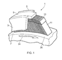
- FIG 1 shows a leaf seal assembly 1.
- the leaf seal assembly 1 comprises first and second substantially parallel annular cover plates 3, 5 that are spaced apart to define an annular channel 7 ( Figure 2 ).
- a plurality of thin resiliently deformable leaf elements 11 that are arranged in an annular pack defining an opening within which a rotatable shaft 30 can be located.
- Each leaf element 11 comprises a spacer 13 which spaces adjacent leaf elements 11.
- the plurality of leaf elements 11 are attached, for example by welding, to a cylindrical backing ring 9 which is located between and is attached to the first and second cover plates 3, 5.
- the first cover plate 3 comprises a circular first inner edge 2 and the second cover plate 5 comprises a circular second inner edge 6 and each of the leaf elements 11 extends beyond the first and second inner edges 2, 6.
- the opening defined by the annular pack of leaf elements 11 is coaxial with the first and second inner edges 2, 6 of the first and second cover plates 3, 5.
- the leaf elements 11 extend at an angle to the true radius and can bend, or flex, along their length
- a first edge 11a of each leaf element 11 is adjacent to an inner surface of the first cover plate 3 and a second edge 11b, parallel to the first edge 11a, of each leaf element 11 is adjacent to an inner surface of the second cover plate 5.
- the inner surface of the first cover plate 3 is spaced from the first edges 11a of the leaf elements 11 by a first gap 15 and the inner surface of the second cover plate 5 is spaced from the second edges 11b of the leaf elements 11 by a second gap 16.
- the second gap 16 is larger than the first gap 15.
- the first cover plate 3 further comprises an axially extending shoulder 4 and the first edge 11a of each leaf element 11 comprises a corresponding step portion 12.
- the leaf seal assembly 1 is positioned between a rotating shaft 30 and a housing 20.
- the rotating shaft 30 is a rotating shaft of a gas turbine engine and the housing 20 is a bearing chamber housing defining a bearing chamber 28; in use the leaf seal assembly 1 will provide a seal to prevent or reduce fluid flow between the bearing chamber 28 and a region 29 outside the bearing chamber.
- the leaf seal assembly 1 is located within a counterbore 22 of the housing 20 and, in this embodiment, is secured in place using a circlip 26 which is located in a cylindrical groove 24.
- the rotating shaft 30 is located within the opening defined by the annular pack of leaf elements 11.
- the rotating shaft 30, annular pack of leaf elements 11, first and second annular cover plates 3, 5 and cylindrical backing ring 9 are all coaxial about an axis 32. It will be appreciated that the exact means for locating and securing the leaf seal assembly is essentially a matter of design choice, and not critical to the operation of the invention.
- each leaf element 11 rests against, or is in contact with, the outer surface of the rotating shaft 30. This provides a seal between the inside and the outside of the bearing chamber housing 20.
- the step portion 12 of each leaf element 11 is spaced from the shoulder 4 of the first cover plate 3.
- the fluidic pressure within the bearing chamber 28 is equal to the pressure outside the chamber (in the region 29) and therefore there is no fluid flow through the leaf seal assembly 1.
- the plurality of leaf elements 11 converge at a position radially outward of the shoulder (4 in Figure 2 ).
- the shaft 30 rotates in a clockwise direction 34 and the pressure within the bearing chamber 28 is lower than the pressure outside the chamber (in region 29). This results in a fluid flow 36, such as an airflow, into the bearing chamber 28.
- the airflow 36 is directed through the gap between the edge of the first cover plate 3 and the rotating shaft 30.
- the airflow meets the contiguous (i.e. solid) arrangement 17 ( Figure 3 ) of leaf elements 11 and is directed radially outwards through the gap between the shoulder 4 of the first cover plate 3 and the step portion 12 of the leaf elements 11.
- the airflow is then directed through the gap 15 between the first edges 11a of the leaf elements 11 and the inner surface of the first cover plate 3 and is directed through the gaps 18 ( Figure 3 ) between adjacent leaf elements 11.
- the airflow then passes into the bearing chamber 28 through the gap between the second cover plate 5 and the rotating shaft 30.
- the gap 16 is larger than the gap 15, the above described airflow 36 through the leaf elements 11 causes an aerodynamic lift on the leaf elements 11 that causes them to resiliently flex along their radial length.
- This causes the inner edges 11c of the leaf elements 11 to lift up and move away from the outer surface of the rotating shaft 30.
- the flow of air 36 into the bearing chamber 28 prevents any fluid, such as oil, from leaking out of the bearing chamber.
- this airflow through the leaf elements 11 causes them to 'blow down' so that the lower edges 11c of the leaf elements 11 are in contact with the outer surface of the rotating shaft 30 and the step portions 12 of the leaf elements 11 are in contact with the shoulder 4 of the first cover plate 3.
- the shoulder 4 and the corresponding step portions 12 of the leaf elements prevent the leaf elements 11 from being blown down too hard against the outer surface of the rotating shaft 30. This prevents the lower edges 11c of the leaf elements 11 from being damaged.
- the shoulder 4 and the corresponding step portions 12 of the leaf elements 11 form a secondary seal (in addition to the seal formed by the lower edges 11c of the leaf elements 11 and the outer surface of the rotating shaft 30) and inhibits the flow of fluid that passes through the gaps 18 between adjacent leaf elements 11 exiting the seal assembly 1. This is because the leaf elements 11 converge at a radial position 19 ( Figure 2 , Figure 3 ) radially outward of the shoulder 4.
- the shoulder 4 may be coated with a wear resistant or abradable layer; or it may be made from, or have an insert of, a polymer or PTFE material.
- the former would avoid damage to the shoulder 4, whilst the latter will improve the effectiveness of the secondary seal in suitably low temperature environments.
- the leaf seal assembly 1 is configured such that when there is a fluid flow in one direction, for example into the bearing chamber housing 20, the leaf elements 11 lift up, thereby allowing a fluid flow into the housing. Conversely, when there is a fluid flow in the opposite direction, for example out of the bearing chamber housing 20, the leaf elements 11 blow down, thereby sealing against fluid exiting the housing 20.
- This effect is achieved by appropriate positioning of the cover plates 3, 5.
- the gaps 15, 16 between the first and second edges 11a, 11b of the leaf elements 11 and their respective cover plates can be chosen to produce this effect.
- the second gap 16 may be larger than the first gap 15.
- the relative sizes of the gaps 15, 16 to produce the desired effect depends on a number of factors including: the dimensions of the leaf elements, the material of the leaf elements, the overall size of the leaf seal, the dimensions of the cover plates, the pressure gradient across the seal, the dimensions of the spacers, and the radial position at which the leaf elements converge.
- the radial position at which the leaf elements converge is influenced by, among other things, the relationship between the leaf thickness and the gap width dictated by the spacers.
- the rotating shaft 30 is provided with a circumferentially extending ramped portion 38 that is located outside the bearing chamber housing 20.
- This ramped portion 38 discourages the airflow 36 from passing straight through the gap created between the lower edges 11c of the leaf elements 11 and the rotating shaft 30 when the leaf elements 11 lift up. This feature is most effective in seal applications where the relative axial displacement between the rotating shaft 30 and the seal 1 is small, such as close to bearings, for example.
- the shoulder 4 in the first cover plate 3 and the corresponding step portions 12 in the leaf elements 11 are absent.
- the first and second edges 11a, 11b of the leaves are straight along their whole lengths, and parallel to each other.
- the gap 15 between the first edges 11a of the leaf elements 11 and the first cover plate 3 is smaller than the gap 16 between the second edges 11b and the second cover plate 5, so that the lift-up and blow-down behaviour of the leaf elements is the same as previously described.
- the invention has been employed to provide a seal against a rotating shaft.
- it could equally well provide a seal where there is no relative rotation but where there is a risk of a pressure reversal in operation (for example in a combustor burner seal for a gas turbine engine).
- the invention therefore provides a leaf seal which can provide an effective seal even when the pressure gradient across the seal is reversed, by the combination of the lift-up and blow-down behaviour of the leaf elements and the provision of cover plates.
- the shoulder and step portions provide a secondary seal that further reduces the fluid flow under pressure reversal conditions.
- a leaf seal according to the invention can therefore be oriented, in use, to take into account the predominant direction of fluid flow through the seal and also to take account of the sealing requirements.
- air flow into the chamber is generally desirable as it prevents oil from flowing out of the seal, whereas air flow out of the chamber is undesirable under all circumstances as it will carry oil with it.
- the combination of features of the seal according to the invention provides a unique seal in which the interaction of lift-up and blow-down behaviours permits the desirable inflow of air, while preventing the undesirable outflow of air and oil.
- the seal acts as a one-way valve.
- a leaf seal according to the invention will, under normal conditions, operate with little or no wear of the leaf element tips or the rotating shaft because the fluid flow will cause the leaf elements to lift up and ride on an air film.
Landscapes
- Engineering & Computer Science (AREA)
- General Engineering & Computer Science (AREA)
- Mechanical Engineering (AREA)
- Chemical & Material Sciences (AREA)
- Combustion & Propulsion (AREA)
- Sealing Devices (AREA)
- Gasket Seals (AREA)
Abstract
Description
- The present invention relates generally to a seal arrangement and in particular to improvements to leaf seals.
- It is frequently necessary to effect a seal in a clearance gap between two components that are capable of relative movement. In particular, seals are often required to seal between a rotatable shaft and a housing surrounding the shaft, the housing having a bore through which the shaft extends.
- Within a gas turbine engine there are shafts that rotate at relatively high speeds and are exposed to pressurised hot gases. Seals are required for these shafts and the seal performance can have a significant effect on the overall efficiency of the gas turbine engine. There are a number of seal designs that have been proposed for such purposes and that are designed to operate within the harsh environment found within a gas turbine engine.
- One type of seal that has been developed for shafts that rotate at relatively high speeds, as found in gas turbine engines, is a brush seal. In such a brush seal, a plurality of fine bristles (such as bronze or stainless steel wire) are held in a carrier mounted on a housing. The tips of the bristles wipe against the shaft so as to effect a seal.
- A problem with such brush seals is that in use the bristles tend to flex in an axial, sealing direction, away from the high pressure side of the seal and towards the low pressure side. Bending of the bristles in this way reduces the effective radial length of the bristles and so reduces the contact between the bristle tips and the shaft, thereby reducing the sealing efficiency. Additionally, flexing of the bristles can clamp the bristles against each other and against a backing member of the seal. Friction between the bristles and the backing member stiffens the bristles and prevents free movement of the bristles so that they no longer follow the shaft. Excursions of the rotating shaft are therefore not accommodated by the bristles. This leads to clearance gaps opening up between the bristle tips and shaft, and at the other extreme increased wear of the bristles, both of which reduce the seal performance.
- An alternative type of seal that has been proposed for gas turbine engines, and also other applications, is a leaf seal. Leaf seals, which are sometimes called foil seals, comprise a number of thin resilient yet flexible strips which are densely packed together with the strips substantially aligned in the sealing direction. One end of the strips is held within a housing whilst the other, radially inner end of the strip extends across the seal gap and rests on the shaft. Such a seal design is described in European Patent Application
EP 0,391,676 . As described, the seal elements, comprising the resilient strips are axially stiff and do not tend to bend in the axial, sealing direction. This type of seal therefore alleviates some of the problems described above in relation to brush seals. - However, the tips of the leaf elements can become damaged and worn by being in constant contact with a rotating shaft. Further, a leaf seal is usually designed for a pressure gradient in one direction only. Therefore, if the direction of the pressure gradient reverses then the seal may fail and fluid may leak.
- It is therefore desirable to have an improved leaf seal which prevents wear of the leaf element tips.
- It is also desirable to have an improved leaf seal which can seal effectively regardless of the pressure gradient.
- According to an aspect of the present invention there is provided a leaf seal assembly as set out in the claims.
- Embodiments of the present invention will now be described, by way of example only, with reference to the accompanying drawings, in which:
-
Figure 1 schematically shows a leaf seal assembly according to an embodiment of the present invention; -
Figure 2 schematically shows a cross-sectional view of the leaf seal assembly ofFigure 1 in a resting state; -
Figure 3 schematically shows the view A-A ofFigure 2 ; -
Figure 4 schematically shows a cross-sectional view of the leaf seal assembly ofFigure 1 in a normal operating condition; -
Figure 5 schematically shows a cross-sectional view of the leaf seal assembly ofFigure 1 during a transient pressure reversal; and -
Figure 6 schematically shows a cross-sectional view of a leaf seal assembly according to a second embodiment. -
Figure 1 shows aleaf seal assembly 1. Theleaf seal assembly 1 comprises first and second substantially parallelannular cover plates Figure 2 ). Within theannular channel 7 is located a plurality of thin resilientlydeformable leaf elements 11 that are arranged in an annular pack defining an opening within which arotatable shaft 30 can be located. Eachleaf element 11 comprises aspacer 13 which spacesadjacent leaf elements 11. The plurality ofleaf elements 11 are attached, for example by welding, to acylindrical backing ring 9 which is located between and is attached to the first andsecond cover plates first cover plate 3 comprises a circular firstinner edge 2 and thesecond cover plate 5 comprises a circular secondinner edge 6 and each of theleaf elements 11 extends beyond the first and secondinner edges leaf elements 11 is coaxial with the first and secondinner edges second cover plates leaf elements 11 extend at an angle to the true radius and can bend, or flex, along their length. - With reference to
Figure 2 , afirst edge 11a of eachleaf element 11 is adjacent to an inner surface of thefirst cover plate 3 and asecond edge 11b, parallel to thefirst edge 11a, of eachleaf element 11 is adjacent to an inner surface of thesecond cover plate 5. The inner surface of thefirst cover plate 3 is spaced from thefirst edges 11a of theleaf elements 11 by afirst gap 15 and the inner surface of thesecond cover plate 5 is spaced from thesecond edges 11b of theleaf elements 11 by asecond gap 16. Thesecond gap 16 is larger than thefirst gap 15. - The
first cover plate 3 further comprises an axially extendingshoulder 4 and thefirst edge 11a of eachleaf element 11 comprises acorresponding step portion 12. - In use, the
leaf seal assembly 1 is positioned between a rotatingshaft 30 and ahousing 20. In this embodiment the rotatingshaft 30 is a rotating shaft of a gas turbine engine and thehousing 20 is a bearing chamber housing defining abearing chamber 28; in use theleaf seal assembly 1 will provide a seal to prevent or reduce fluid flow between thebearing chamber 28 and aregion 29 outside the bearing chamber. Theleaf seal assembly 1 is located within acounterbore 22 of thehousing 20 and, in this embodiment, is secured in place using acirclip 26 which is located in acylindrical groove 24. The rotatingshaft 30 is located within the opening defined by the annular pack ofleaf elements 11. The rotatingshaft 30, annular pack ofleaf elements 11, first and secondannular cover plates cylindrical backing ring 9 are all coaxial about anaxis 32. It will be appreciated that the exact means for locating and securing the leaf seal assembly is essentially a matter of design choice, and not critical to the operation of the invention. - In a stationary or resting state (shown in
Figure 2 ), a radially inner (or third)edge 11c of eachleaf element 11 rests against, or is in contact with, the outer surface of the rotatingshaft 30. This provides a seal between the inside and the outside of thebearing chamber housing 20. Thestep portion 12 of eachleaf element 11 is spaced from theshoulder 4 of thefirst cover plate 3. The fluidic pressure within thebearing chamber 28 is equal to the pressure outside the chamber (in the region 29) and therefore there is no fluid flow through theleaf seal assembly 1. - Referring now to
Figure 3 , in the resting state the plurality ofleaf elements 11 converge at aradial position 19 radially outward of the first innercircular edge 2 of the first cover plate 3 (thefirst cover plate 3 is shown as transparent inFigure 3 for clarity). This results in acontiguous arrangement 17 ofleaf elements 11 between the rotating shaft (30 inFigure 2 ) and theedge 2 of thefirst cover plate 3, which inhibits or eliminates leakage betweenadjacent leaf elements 11. Radially outward from the position where the leaf elements converge 19 there aregaps 18 between adjacent leaf elements. Therefore, there may (if there is a pressure difference between thebearing chamber 28 and theregion 29 ofFigure 2 ) be leakage flow betweenadjacent leaves 11 in these radially outward positions, but any such leakage will be minimised by the proximity of thefirst cover plate 3 to the leaves 11 (as shown bygap 15 inFigure 2 ). - Also, in this embodiment the plurality of
leaf elements 11 converge at a position radially outward of the shoulder (4 inFigure 2 ). - With reference to
Figure 4 , in use, and under normal running conditions, theshaft 30 rotates in aclockwise direction 34 and the pressure within thebearing chamber 28 is lower than the pressure outside the chamber (in region 29). This results in afluid flow 36, such as an airflow, into thebearing chamber 28. Theairflow 36 is directed through the gap between the edge of thefirst cover plate 3 and the rotatingshaft 30. The airflow meets the contiguous (i.e. solid) arrangement 17 (Figure 3 ) ofleaf elements 11 and is directed radially outwards through the gap between theshoulder 4 of thefirst cover plate 3 and thestep portion 12 of theleaf elements 11. The airflow is then directed through thegap 15 between thefirst edges 11a of theleaf elements 11 and the inner surface of thefirst cover plate 3 and is directed through the gaps 18 (Figure 3 ) betweenadjacent leaf elements 11. The airflow then passes into the bearingchamber 28 through the gap between thesecond cover plate 5 and therotating shaft 30. Because thegap 16 is larger than thegap 15, the above describedairflow 36 through theleaf elements 11 causes an aerodynamic lift on theleaf elements 11 that causes them to resiliently flex along their radial length. This causes theinner edges 11c of theleaf elements 11 to lift up and move away from the outer surface of therotating shaft 30. This prevents thelower edges 11c of theleaf elements 11 from wearing and provides an air film in the gap between thelower edges 11c of theleaf elements 11 and the outer surface of therotating shaft 30. The flow ofair 36 into the bearingchamber 28 prevents any fluid, such as oil, from leaking out of the bearing chamber. - With reference to
Figure 5 , in a transient pressure reversal, such as may occur during engine start-up, the pressure within the bearingchamber 28 becomes higher than the pressure outside the chamber. There is therefore a tendency for afluid flow 36, such as an airflow, from the inside to the outside of the bearingchamber housing 20. Theairflow 36 is directed through the gap between the edge of thesecond cover plate 5 and the outer surface of therotating shaft 30. Theairflow 36 is directed radially outwards through thegap 16 between thesecond edges 11b of theleaf elements 11 and the inner surface of thesecond cover plate 5 and then passes through the gaps 18 (Figure 3 ) betweenadjacent leaf elements 11. Because thegap 15 is smaller than thegap 16, this airflow through theleaf elements 11 causes them to 'blow down' so that thelower edges 11c of theleaf elements 11 are in contact with the outer surface of therotating shaft 30 and thestep portions 12 of theleaf elements 11 are in contact with theshoulder 4 of thefirst cover plate 3. Theshoulder 4 and thecorresponding step portions 12 of the leaf elements prevent theleaf elements 11 from being blown down too hard against the outer surface of therotating shaft 30. This prevents thelower edges 11c of theleaf elements 11 from being damaged. Further, theshoulder 4 and thecorresponding step portions 12 of theleaf elements 11 form a secondary seal (in addition to the seal formed by thelower edges 11c of theleaf elements 11 and the outer surface of the rotating shaft 30) and inhibits the flow of fluid that passes through thegaps 18 betweenadjacent leaf elements 11 exiting theseal assembly 1. This is because theleaf elements 11 converge at a radial position 19 (Figure 2 ,Figure 3 ) radially outward of theshoulder 4. - The contact between the
lower edges 11c of theleaf elements 11 and the outer surface of therotating shaft 30, and the contact between thestep portions 12 of theleaf elements 11 and theshoulder 4 of thefirst cover plate 3, in combination with thecontiguous arrangement 17 ofleaf elements 11 between therotating shaft 30 and theedge 2 of thefirst cover plate 3, prevents fluid from flowing from the inside to the outside of the bearinghousing chamber 20 during a transient pressure reversal. - The
shoulder 4 may be coated with a wear resistant or abradable layer; or it may be made from, or have an insert of, a polymer or PTFE material. The former would avoid damage to theshoulder 4, whilst the latter will improve the effectiveness of the secondary seal in suitably low temperature environments. - The
leaf seal assembly 1 is configured such that when there is a fluid flow in one direction, for example into the bearingchamber housing 20, theleaf elements 11 lift up, thereby allowing a fluid flow into the housing. Conversely, when there is a fluid flow in the opposite direction, for example out of the bearingchamber housing 20, theleaf elements 11 blow down, thereby sealing against fluid exiting thehousing 20. This effect is achieved by appropriate positioning of thecover plates gaps second edges leaf elements 11 and their respective cover plates can be chosen to produce this effect. Thesecond gap 16 may be larger than thefirst gap 15. However, the relative sizes of thegaps - As shown in
Figure 6 , in a second embodiment the rotatingshaft 30 is provided with a circumferentially extending rampedportion 38 that is located outside the bearingchamber housing 20. This rampedportion 38 discourages theairflow 36 from passing straight through the gap created between thelower edges 11c of theleaf elements 11 and therotating shaft 30 when theleaf elements 11 lift up. This feature is most effective in seal applications where the relative axial displacement between therotating shaft 30 and theseal 1 is small, such as close to bearings, for example. - In a further embodiment of the invention, not shown in the drawings, the
shoulder 4 in thefirst cover plate 3 and thecorresponding step portions 12 in theleaf elements 11 are absent. The first andsecond edges gap 15 between thefirst edges 11a of theleaf elements 11 and thefirst cover plate 3 is smaller than thegap 16 between thesecond edges 11b and thesecond cover plate 5, so that the lift-up and blow-down behaviour of the leaf elements is the same as previously described. Although the absence of the shoulder and step portions means that there will be no secondary seal (as described above with reference toFigure 5 ) under pressure reversal conditions, it is anticipated that such a leaf seal assembly would still effectively prevent fluid flow from the inside to the outside of the bearingchamber 28. Thecontiguous arrangement 17 ofleaf elements 11 between therotating shaft 30 and theedge 2 of thefirst cover plate 3 will prevent fluid flow through that radially inner portion of theleaf elements 11, and the blow-down of the leaf elements against the rotatingshaft 30 will prevent fluid flow between thethird edges 11c and therotating shaft 30. Although fluid may flow through thegaps 18 between theleaf elements 11, the presence of the first cover plate, and in particular the smallness of thegap 15, will impede this flow and minimise the fluid leakage under pressure reversal conditions. - In the embodiments described, the invention has been employed to provide a seal against a rotating shaft. However, it could equally well provide a seal where there is no relative rotation but where there is a risk of a pressure reversal in operation (for example in a combustor burner seal for a gas turbine engine).
- The invention therefore provides a leaf seal which can provide an effective seal even when the pressure gradient across the seal is reversed, by the combination of the lift-up and blow-down behaviour of the leaf elements and the provision of cover plates. In a preferred embodiment of the invention, the shoulder and step portions provide a secondary seal that further reduces the fluid flow under pressure reversal conditions. A leaf seal according to the invention can therefore be oriented, in use, to take into account the predominant direction of fluid flow through the seal and also to take account of the sealing requirements. In the context of a bearing chamber, air flow into the chamber is generally desirable as it prevents oil from flowing out of the seal, whereas air flow out of the chamber is undesirable under all circumstances as it will carry oil with it. The combination of features of the seal according to the invention provides a unique seal in which the interaction of lift-up and blow-down behaviours permits the desirable inflow of air, while preventing the undesirable outflow of air and oil. In effect, the seal acts as a one-way valve.
- In an application in which there is relative rotation between the leaf seal and the component it seals against, a leaf seal according to the invention will, under normal conditions, operate with little or no wear of the leaf element tips or the rotating shaft because the fluid flow will cause the leaf elements to lift up and ride on an air film.
Claims (11)
- A leaf seal assembly (1) for providing a fluidic seal between a first member (30) and a second member (20), comprising:first and second cover plates (3, 5) defining a channel (7) therebetween, the first cover plate having a first inner edge (2) and the second cover plate having a second inner edge (6);a plurality of leaf elements (11) located within the channel, each leaf element having first and second leaf edges (11a, 11b) adjacent to the first and second cover plates respectively, wherein a projecting portion of each leaf element extends beyond the first and second inner edges;wherein the seal assembly is configured such that when it is located between a first member and a second member;a fluid flow (36) in a first direction from the first cover plate side (3) of the seal assembly to the second cover plate side (5) of the seal assembly causes the plurality of leaf elements to move away from the first member to create a fluid passage between the plurality of leaf elements and the first member, thereby allowing a flow of fluid through the seal in the first direction; anda fluid flow in a second direction from the second cover plate side (5) of the seal assembly to the first cover plate side (3) of the assembly causes the plurality of leaf elements to move towards the first member such that a third leaf edge (11c) of the projecting portion of each of the leaf elements contacts the first member, thereby opposing the flow of fluid through the seal in the second direction.
- A leaf seal assembly as claimed in claim 1, wherein when there is a fluid flow in the second direction, the movement of the plurality of leaf elements towards the first member causes the leaf elements to converge and thereby to oppose the fluid flow in the second direction.
- A leaf seal assembly according to claim 2, wherein the leaf elements converge at a position radially outward of the inner edge of the first cover plate.
- A leaf seal assembly according to claim 2 or claim 3, wherein the first cover plate further comprises a shoulder (4) that extends into the channel and each of the plurality of leaf elements comprises a step portion (12) corresponding to the shoulder, wherein when there is a fluid flow in the second direction, the step portion of each of the leaf elements contacts the shoulder.
- A leaf seal assembly according to claim 4, wherein the leaf elements converge at a position radially outward of the shoulder.
- A leaf seal assembly according to any one of the preceding claims, wherein there is a first gap (15) between the first leaf edges of the plurality of leaf elements and an inner surface of the first cover plate and a second gap (16) between the second leaf edges of the plurality of leaf elements and an inner surface of the second cover plate, the second gap being larger than the first gap.
- A leaf seal assembly according to any one of the preceding claims, wherein the first member is a rotatable shaft and the plurality of leaf elements are arranged in an annular pack defining an opening within which the rotatable shaft can be received.
- A leaf seal assembly according to claim 7, wherein one or both of the first and second inner edges of the cover plates are circular and are substantially coaxial with the opening defined by the annular pack of leaf elements.
- An assembly comprising the leaf seal assembly according to any preceding claim located between a bearing chamber housing and a rotatable shaft.
- An assembly according to claim 9, wherein the fluid flow in the first direction is into the bearing chamber housing (20) and the fluid flow in the second direction is out of the bearing chamber housing (20).
- A gas turbine engine comprising a leaf seal assembly according to any of claims 1-8 or an assembly according to claim 9 or claim 10.
Applications Claiming Priority (1)
| Application Number | Priority Date | Filing Date | Title |
|---|---|---|---|
| GBGB1121440.0A GB201121440D0 (en) | 2011-12-14 | 2011-12-14 | Improved leaf seal |
Publications (2)
| Publication Number | Publication Date |
|---|---|
| EP2604894A1 true EP2604894A1 (en) | 2013-06-19 |
| EP2604894B1 EP2604894B1 (en) | 2015-02-25 |
Family
ID=45560410
Family Applications (1)
| Application Number | Title | Priority Date | Filing Date |
|---|---|---|---|
| EP12195218.8A Active EP2604894B1 (en) | 2011-12-14 | 2012-12-03 | Improved leaf seal |
Country Status (3)
| Country | Link |
|---|---|
| US (1) | US8794633B2 (en) |
| EP (1) | EP2604894B1 (en) |
| GB (1) | GB201121440D0 (en) |
Cited By (4)
| Publication number | Priority date | Publication date | Assignee | Title |
|---|---|---|---|---|
| EP2669555A1 (en) * | 2012-05-31 | 2013-12-04 | Rolls-Royce plc | Leaf seal |
| GB2523139A (en) * | 2014-02-14 | 2015-08-19 | Rolls Royce Plc | A leaf seal |
| EP3217045A4 (en) * | 2014-12-16 | 2018-01-03 | Mitsubishi Hitachi Power Systems, Ltd. | Shaft seal mechanism |
| US11872150B2 (en) | 2020-12-28 | 2024-01-16 | Ossur Iceland Ehf | Sleeve and method for use with orthopedic device |
Families Citing this family (4)
| Publication number | Priority date | Publication date | Assignee | Title |
|---|---|---|---|---|
| US10208674B2 (en) * | 2013-03-13 | 2019-02-19 | United Technologies Corporation | Multi-axial brush seal |
| GB201311612D0 (en) * | 2013-06-28 | 2013-08-14 | Rolls Royce Plc | A Leaf Seal |
| JP5848372B2 (en) * | 2014-01-28 | 2016-01-27 | 三菱重工業株式会社 | Shaft seal device and rotary machine |
| JP6276209B2 (en) | 2015-02-20 | 2018-02-07 | 三菱日立パワーシステムズ株式会社 | Turbine sealing device and turbine, and thin plate for sealing device |
Citations (3)
| Publication number | Priority date | Publication date | Assignee | Title |
|---|---|---|---|---|
| EP1231416A2 (en) * | 2001-02-08 | 2002-08-14 | Mitsubishi Heavy Industries, Ltd. | Shaft seal and gas turbine |
| WO2006016098A1 (en) * | 2004-08-07 | 2006-02-16 | Rolls-Royce Plc | A leaf seal arrangement |
| EP2336609A1 (en) * | 2009-12-18 | 2011-06-22 | Rolls-Royce plc | A leaf seal assembly |
Family Cites Families (8)
| Publication number | Priority date | Publication date | Assignee | Title |
|---|---|---|---|---|
| GB8907695D0 (en) | 1989-04-05 | 1989-05-17 | Cross Mfg Co | Seals |
| JP3593082B2 (en) | 2001-10-09 | 2004-11-24 | 三菱重工業株式会社 | Shaft seal mechanism and turbine |
| DE102004020378A1 (en) * | 2004-04-23 | 2005-11-10 | Alstom Technology Ltd | Lamella seal, in particular for a gas turbine, and method for its production |
| JP3917993B2 (en) * | 2004-08-10 | 2007-05-23 | 三菱重工業株式会社 | A shaft seal mechanism, a structure for attaching the shaft seal mechanism to a stator, and a turbine including these. |
| US7413194B2 (en) * | 2004-10-28 | 2008-08-19 | Rolls-Royce Plc | Pressure balanced annular seal |
| US7976026B2 (en) * | 2007-04-30 | 2011-07-12 | General Electric Company | Methods and apparatus to facilitate sealing in rotary machines |
| GB2461279A (en) | 2008-06-25 | 2009-12-30 | Rolls Royce Plc | Leaf seal which is resistant to flutter |
| GB0919708D0 (en) | 2009-11-11 | 2009-12-30 | Alstom Technology Ltd | Leaf seal |
-
2011
- 2011-12-14 GB GBGB1121440.0A patent/GB201121440D0/en not_active Ceased
-
2012
- 2012-12-03 US US13/692,609 patent/US8794633B2/en active Active
- 2012-12-03 EP EP12195218.8A patent/EP2604894B1/en active Active
Patent Citations (3)
| Publication number | Priority date | Publication date | Assignee | Title |
|---|---|---|---|---|
| EP1231416A2 (en) * | 2001-02-08 | 2002-08-14 | Mitsubishi Heavy Industries, Ltd. | Shaft seal and gas turbine |
| WO2006016098A1 (en) * | 2004-08-07 | 2006-02-16 | Rolls-Royce Plc | A leaf seal arrangement |
| EP2336609A1 (en) * | 2009-12-18 | 2011-06-22 | Rolls-Royce plc | A leaf seal assembly |
Cited By (6)
| Publication number | Priority date | Publication date | Assignee | Title |
|---|---|---|---|---|
| EP2669555A1 (en) * | 2012-05-31 | 2013-12-04 | Rolls-Royce plc | Leaf seal |
| US9057444B2 (en) | 2012-05-31 | 2015-06-16 | Rolls-Royce Plc | Leaf seal |
| GB2523139A (en) * | 2014-02-14 | 2015-08-19 | Rolls Royce Plc | A leaf seal |
| EP3217045A4 (en) * | 2014-12-16 | 2018-01-03 | Mitsubishi Hitachi Power Systems, Ltd. | Shaft seal mechanism |
| US10174844B2 (en) | 2014-12-16 | 2019-01-08 | Mitsubishi Hitachi Power Systems, Ltd. | Shaft seal mechanism |
| US11872150B2 (en) | 2020-12-28 | 2024-01-16 | Ossur Iceland Ehf | Sleeve and method for use with orthopedic device |
Also Published As
| Publication number | Publication date |
|---|---|
| EP2604894B1 (en) | 2015-02-25 |
| US8794633B2 (en) | 2014-08-05 |
| GB201121440D0 (en) | 2012-01-25 |
| US20130154199A1 (en) | 2013-06-20 |
Similar Documents
| Publication | Publication Date | Title |
|---|---|---|
| EP2604894B1 (en) | Improved leaf seal | |
| EP1890059B1 (en) | Compliant plate seals for turbomachinery | |
| EP2580498B1 (en) | Film riding pressure actuated leaf seal assembly | |
| JP5553853B2 (en) | Film riding seal for turbine | |
| US8382120B2 (en) | Method and apparatus for compliant plate seals | |
| EP2670954B1 (en) | Axial brush seal | |
| EP2318738B1 (en) | Leaf seal | |
| CN102918308B (en) | Shaft seal mechanism and possess the rotating machinery of this mechanism | |
| JP3616016B2 (en) | Shaft seal mechanism and gas turbine | |
| US9206904B2 (en) | Seal including flexible seal strips | |
| EP2546466B1 (en) | Shaft seal device and rotary machine with shaft seal device | |
| US8152462B1 (en) | Card seal with conical flexible seal | |
| EP2971586B1 (en) | Self-adjusting non-contact seal | |
| US8690158B2 (en) | Axially angled annular seals | |
| US9829007B2 (en) | Turbine sealing system | |
| EP3002487A1 (en) | Sealing system | |
| WO2008140451A1 (en) | Non-contacting seal for rotating surfaces | |
| EP1574671B1 (en) | Turbine engine | |
| JP6191844B2 (en) | Shaft seal device and rotary machine provided with the same | |
| WO2016132966A1 (en) | Seal device for turbine, turbine, and thin plate for seal device | |
| KR101950127B1 (en) | Shaft seal mechanism |
Legal Events
| Date | Code | Title | Description |
|---|---|---|---|
| PUAI | Public reference made under article 153(3) epc to a published international application that has entered the european phase |
Free format text: ORIGINAL CODE: 0009012 |
|
| AK | Designated contracting states |
Kind code of ref document: A1 Designated state(s): AL AT BE BG CH CY CZ DE DK EE ES FI FR GB GR HR HU IE IS IT LI LT LU LV MC MK MT NL NO PL PT RO RS SE SI SK SM TR |
|
| AX | Request for extension of the european patent |
Extension state: BA ME |
|
| 17P | Request for examination filed |
Effective date: 20131209 |
|
| RBV | Designated contracting states (corrected) |
Designated state(s): AL AT BE BG CH CY CZ DE DK EE ES FI FR GB GR HR HU IE IS IT LI LT LU LV MC MK MT NL NO PL PT RO RS SE SI SK SM TR |
|
| GRAP | Despatch of communication of intention to grant a patent |
Free format text: ORIGINAL CODE: EPIDOSNIGR1 |
|
| INTG | Intention to grant announced |
Effective date: 20141118 |
|
| GRAS | Grant fee paid |
Free format text: ORIGINAL CODE: EPIDOSNIGR3 |
|
| GRAA | (expected) grant |
Free format text: ORIGINAL CODE: 0009210 |
|
| AK | Designated contracting states |
Kind code of ref document: B1 Designated state(s): AL AT BE BG CH CY CZ DE DK EE ES FI FR GB GR HR HU IE IS IT LI LT LU LV MC MK MT NL NO PL PT RO RS SE SI SK SM TR |
|
| REG | Reference to a national code |
Ref country code: GB Ref legal event code: FG4D |
|
| REG | Reference to a national code |
Ref country code: CH Ref legal event code: EP |
|
| REG | Reference to a national code |
Ref country code: IE Ref legal event code: FG4D |
|
| REG | Reference to a national code |
Ref country code: DE Ref legal event code: R096 Ref document number: 602012005432 Country of ref document: DE Effective date: 20150409 |
|
| REG | Reference to a national code |
Ref country code: AT Ref legal event code: REF Ref document number: 712281 Country of ref document: AT Kind code of ref document: T Effective date: 20150415 |
|
| REG | Reference to a national code |
Ref country code: NL Ref legal event code: VDEP Effective date: 20150225 |
|
| REG | Reference to a national code |
Ref country code: AT Ref legal event code: MK05 Ref document number: 712281 Country of ref document: AT Kind code of ref document: T Effective date: 20150225 |
|
| REG | Reference to a national code |
Ref country code: LT Ref legal event code: MG4D |
|
| RAP2 | Party data changed (patent owner data changed or rights of a patent transferred) |
Owner name: ROLLS-ROYCE PLC |
|
| PG25 | Lapsed in a contracting state [announced via postgrant information from national office to epo] |
Ref country code: LT Free format text: LAPSE BECAUSE OF FAILURE TO SUBMIT A TRANSLATION OF THE DESCRIPTION OR TO PAY THE FEE WITHIN THE PRESCRIBED TIME-LIMIT Effective date: 20150225 Ref country code: SE Free format text: LAPSE BECAUSE OF FAILURE TO SUBMIT A TRANSLATION OF THE DESCRIPTION OR TO PAY THE FEE WITHIN THE PRESCRIBED TIME-LIMIT Effective date: 20150225 Ref country code: ES Free format text: LAPSE BECAUSE OF FAILURE TO SUBMIT A TRANSLATION OF THE DESCRIPTION OR TO PAY THE FEE WITHIN THE PRESCRIBED TIME-LIMIT Effective date: 20150225 Ref country code: HR Free format text: LAPSE BECAUSE OF FAILURE TO SUBMIT A TRANSLATION OF THE DESCRIPTION OR TO PAY THE FEE WITHIN THE PRESCRIBED TIME-LIMIT Effective date: 20150225 Ref country code: FI Free format text: LAPSE BECAUSE OF FAILURE TO SUBMIT A TRANSLATION OF THE DESCRIPTION OR TO PAY THE FEE WITHIN THE PRESCRIBED TIME-LIMIT Effective date: 20150225 Ref country code: NO Free format text: LAPSE BECAUSE OF FAILURE TO SUBMIT A TRANSLATION OF THE DESCRIPTION OR TO PAY THE FEE WITHIN THE PRESCRIBED TIME-LIMIT Effective date: 20150525 |
|
| PG25 | Lapsed in a contracting state [announced via postgrant information from national office to epo] |
Ref country code: RS Free format text: LAPSE BECAUSE OF FAILURE TO SUBMIT A TRANSLATION OF THE DESCRIPTION OR TO PAY THE FEE WITHIN THE PRESCRIBED TIME-LIMIT Effective date: 20150225 Ref country code: GR Free format text: LAPSE BECAUSE OF FAILURE TO SUBMIT A TRANSLATION OF THE DESCRIPTION OR TO PAY THE FEE WITHIN THE PRESCRIBED TIME-LIMIT Effective date: 20150526 Ref country code: AT Free format text: LAPSE BECAUSE OF FAILURE TO SUBMIT A TRANSLATION OF THE DESCRIPTION OR TO PAY THE FEE WITHIN THE PRESCRIBED TIME-LIMIT Effective date: 20150225 Ref country code: IS Free format text: LAPSE BECAUSE OF FAILURE TO SUBMIT A TRANSLATION OF THE DESCRIPTION OR TO PAY THE FEE WITHIN THE PRESCRIBED TIME-LIMIT Effective date: 20150625 Ref country code: LV Free format text: LAPSE BECAUSE OF FAILURE TO SUBMIT A TRANSLATION OF THE DESCRIPTION OR TO PAY THE FEE WITHIN THE PRESCRIBED TIME-LIMIT Effective date: 20150225 |
|
| PG25 | Lapsed in a contracting state [announced via postgrant information from national office to epo] |
Ref country code: NL Free format text: LAPSE BECAUSE OF FAILURE TO SUBMIT A TRANSLATION OF THE DESCRIPTION OR TO PAY THE FEE WITHIN THE PRESCRIBED TIME-LIMIT Effective date: 20150225 |
|
| PG25 | Lapsed in a contracting state [announced via postgrant information from national office to epo] |
Ref country code: RO Free format text: LAPSE BECAUSE OF FAILURE TO SUBMIT A TRANSLATION OF THE DESCRIPTION OR TO PAY THE FEE WITHIN THE PRESCRIBED TIME-LIMIT Effective date: 20150225 Ref country code: DK Free format text: LAPSE BECAUSE OF FAILURE TO SUBMIT A TRANSLATION OF THE DESCRIPTION OR TO PAY THE FEE WITHIN THE PRESCRIBED TIME-LIMIT Effective date: 20150225 Ref country code: EE Free format text: LAPSE BECAUSE OF FAILURE TO SUBMIT A TRANSLATION OF THE DESCRIPTION OR TO PAY THE FEE WITHIN THE PRESCRIBED TIME-LIMIT Effective date: 20150225 Ref country code: CZ Free format text: LAPSE BECAUSE OF FAILURE TO SUBMIT A TRANSLATION OF THE DESCRIPTION OR TO PAY THE FEE WITHIN THE PRESCRIBED TIME-LIMIT Effective date: 20150225 Ref country code: SK Free format text: LAPSE BECAUSE OF FAILURE TO SUBMIT A TRANSLATION OF THE DESCRIPTION OR TO PAY THE FEE WITHIN THE PRESCRIBED TIME-LIMIT Effective date: 20150225 |
|
| REG | Reference to a national code |
Ref country code: DE Ref legal event code: R097 Ref document number: 602012005432 Country of ref document: DE |
|
| PG25 | Lapsed in a contracting state [announced via postgrant information from national office to epo] |
Ref country code: PL Free format text: LAPSE BECAUSE OF FAILURE TO SUBMIT A TRANSLATION OF THE DESCRIPTION OR TO PAY THE FEE WITHIN THE PRESCRIBED TIME-LIMIT Effective date: 20150225 |
|
| REG | Reference to a national code |
Ref country code: FR Ref legal event code: PLFP Year of fee payment: 4 |
|
| PG25 | Lapsed in a contracting state [announced via postgrant information from national office to epo] |
Ref country code: IT Free format text: LAPSE BECAUSE OF FAILURE TO SUBMIT A TRANSLATION OF THE DESCRIPTION OR TO PAY THE FEE WITHIN THE PRESCRIBED TIME-LIMIT Effective date: 20150225 |
|
| PLBE | No opposition filed within time limit |
Free format text: ORIGINAL CODE: 0009261 |
|
| STAA | Information on the status of an ep patent application or granted ep patent |
Free format text: STATUS: NO OPPOSITION FILED WITHIN TIME LIMIT |
|
| 26N | No opposition filed |
Effective date: 20151126 |
|
| PG25 | Lapsed in a contracting state [announced via postgrant information from national office to epo] |
Ref country code: SI Free format text: LAPSE BECAUSE OF FAILURE TO SUBMIT A TRANSLATION OF THE DESCRIPTION OR TO PAY THE FEE WITHIN THE PRESCRIBED TIME-LIMIT Effective date: 20150225 |
|
| REG | Reference to a national code |
Ref country code: DE Ref legal event code: R082 Ref document number: 602012005432 Country of ref document: DE Representative=s name: HERNANDEZ, YORCK, DIPL.-ING., DE |
|
| PG25 | Lapsed in a contracting state [announced via postgrant information from national office to epo] |
Ref country code: BE Free format text: LAPSE BECAUSE OF FAILURE TO SUBMIT A TRANSLATION OF THE DESCRIPTION OR TO PAY THE FEE WITHIN THE PRESCRIBED TIME-LIMIT Effective date: 20150225 |
|
| PG25 | Lapsed in a contracting state [announced via postgrant information from national office to epo] |
Ref country code: MC Free format text: LAPSE BECAUSE OF FAILURE TO SUBMIT A TRANSLATION OF THE DESCRIPTION OR TO PAY THE FEE WITHIN THE PRESCRIBED TIME-LIMIT Effective date: 20150225 Ref country code: LU Free format text: LAPSE BECAUSE OF FAILURE TO SUBMIT A TRANSLATION OF THE DESCRIPTION OR TO PAY THE FEE WITHIN THE PRESCRIBED TIME-LIMIT Effective date: 20151203 |
|
| REG | Reference to a national code |
Ref country code: CH Ref legal event code: PL |
|
| REG | Reference to a national code |
Ref country code: IE Ref legal event code: MM4A |
|
| PG25 | Lapsed in a contracting state [announced via postgrant information from national office to epo] |
Ref country code: IE Free format text: LAPSE BECAUSE OF NON-PAYMENT OF DUE FEES Effective date: 20151203 Ref country code: LI Free format text: LAPSE BECAUSE OF NON-PAYMENT OF DUE FEES Effective date: 20151231 Ref country code: CH Free format text: LAPSE BECAUSE OF NON-PAYMENT OF DUE FEES Effective date: 20151231 |
|
| REG | Reference to a national code |
Ref country code: FR Ref legal event code: PLFP Year of fee payment: 5 |
|
| PG25 | Lapsed in a contracting state [announced via postgrant information from national office to epo] |
Ref country code: BG Free format text: LAPSE BECAUSE OF FAILURE TO SUBMIT A TRANSLATION OF THE DESCRIPTION OR TO PAY THE FEE WITHIN THE PRESCRIBED TIME-LIMIT Effective date: 20150225 Ref country code: SM Free format text: LAPSE BECAUSE OF FAILURE TO SUBMIT A TRANSLATION OF THE DESCRIPTION OR TO PAY THE FEE WITHIN THE PRESCRIBED TIME-LIMIT Effective date: 20150225 Ref country code: HU Free format text: LAPSE BECAUSE OF FAILURE TO SUBMIT A TRANSLATION OF THE DESCRIPTION OR TO PAY THE FEE WITHIN THE PRESCRIBED TIME-LIMIT; INVALID AB INITIO Effective date: 20121203 |
|
| PG25 | Lapsed in a contracting state [announced via postgrant information from national office to epo] |
Ref country code: CY Free format text: LAPSE BECAUSE OF FAILURE TO SUBMIT A TRANSLATION OF THE DESCRIPTION OR TO PAY THE FEE WITHIN THE PRESCRIBED TIME-LIMIT Effective date: 20150225 |
|
| PG25 | Lapsed in a contracting state [announced via postgrant information from national office to epo] |
Ref country code: MT Free format text: LAPSE BECAUSE OF FAILURE TO SUBMIT A TRANSLATION OF THE DESCRIPTION OR TO PAY THE FEE WITHIN THE PRESCRIBED TIME-LIMIT Effective date: 20150225 |
|
| REG | Reference to a national code |
Ref country code: FR Ref legal event code: PLFP Year of fee payment: 6 |
|
| PG25 | Lapsed in a contracting state [announced via postgrant information from national office to epo] |
Ref country code: PT Free format text: LAPSE BECAUSE OF FAILURE TO SUBMIT A TRANSLATION OF THE DESCRIPTION OR TO PAY THE FEE WITHIN THE PRESCRIBED TIME-LIMIT Effective date: 20150225 Ref country code: MK Free format text: LAPSE BECAUSE OF FAILURE TO SUBMIT A TRANSLATION OF THE DESCRIPTION OR TO PAY THE FEE WITHIN THE PRESCRIBED TIME-LIMIT Effective date: 20150225 Ref country code: TR Free format text: LAPSE BECAUSE OF FAILURE TO SUBMIT A TRANSLATION OF THE DESCRIPTION OR TO PAY THE FEE WITHIN THE PRESCRIBED TIME-LIMIT Effective date: 20150225 |
|
| PG25 | Lapsed in a contracting state [announced via postgrant information from national office to epo] |
Ref country code: AL Free format text: LAPSE BECAUSE OF FAILURE TO SUBMIT A TRANSLATION OF THE DESCRIPTION OR TO PAY THE FEE WITHIN THE PRESCRIBED TIME-LIMIT Effective date: 20150225 |
|
| P01 | Opt-out of the competence of the unified patent court (upc) registered |
Effective date: 20230528 |
|
| PGFP | Annual fee paid to national office [announced via postgrant information from national office to epo] |
Ref country code: GB Payment date: 20251223 Year of fee payment: 14 |
|
| PGFP | Annual fee paid to national office [announced via postgrant information from national office to epo] |
Ref country code: FR Payment date: 20251230 Year of fee payment: 14 |
|
| PGFP | Annual fee paid to national office [announced via postgrant information from national office to epo] |
Ref country code: DE Payment date: 20251229 Year of fee payment: 14 |