EP2604794A1 - Electrical Grounding for Fan Blades - Google Patents
Electrical Grounding for Fan Blades Download PDFInfo
- Publication number
- EP2604794A1 EP2604794A1 EP12196763.2A EP12196763A EP2604794A1 EP 2604794 A1 EP2604794 A1 EP 2604794A1 EP 12196763 A EP12196763 A EP 12196763A EP 2604794 A1 EP2604794 A1 EP 2604794A1
- Authority
- EP
- European Patent Office
- Prior art keywords
- rotor
- fan
- sheath
- set forth
- grounding element
- Prior art date
- Legal status (The legal status is an assumption and is not a legal conclusion. Google has not performed a legal analysis and makes no representation as to the accuracy of the status listed.)
- Granted
Links
Images

Classifications
-
- F—MECHANICAL ENGINEERING; LIGHTING; HEATING; WEAPONS; BLASTING
- F01—MACHINES OR ENGINES IN GENERAL; ENGINE PLANTS IN GENERAL; STEAM ENGINES
- F01D—NON-POSITIVE DISPLACEMENT MACHINES OR ENGINES, e.g. STEAM TURBINES
- F01D5/00—Blades; Blade-carrying members; Heating, heat-insulating, cooling or antivibration means on the blades or the members
- F01D5/30—Fixing blades to rotors; Blade roots ; Blade spacers
-
- F—MECHANICAL ENGINEERING; LIGHTING; HEATING; WEAPONS; BLASTING
- F01—MACHINES OR ENGINES IN GENERAL; ENGINE PLANTS IN GENERAL; STEAM ENGINES
- F01D—NON-POSITIVE DISPLACEMENT MACHINES OR ENGINES, e.g. STEAM TURBINES
- F01D25/00—Component parts, details, or accessories, not provided for in, or of interest apart from, other groups
- F01D25/28—Supporting or mounting arrangements, e.g. for turbine casing
-
- F—MECHANICAL ENGINEERING; LIGHTING; HEATING; WEAPONS; BLASTING
- F01—MACHINES OR ENGINES IN GENERAL; ENGINE PLANTS IN GENERAL; STEAM ENGINES
- F01D—NON-POSITIVE DISPLACEMENT MACHINES OR ENGINES, e.g. STEAM TURBINES
- F01D5/00—Blades; Blade-carrying members; Heating, heat-insulating, cooling or antivibration means on the blades or the members
- F01D5/02—Blade-carrying members, e.g. rotors
-
- F—MECHANICAL ENGINEERING; LIGHTING; HEATING; WEAPONS; BLASTING
- F01—MACHINES OR ENGINES IN GENERAL; ENGINE PLANTS IN GENERAL; STEAM ENGINES
- F01D—NON-POSITIVE DISPLACEMENT MACHINES OR ENGINES, e.g. STEAM TURBINES
- F01D5/00—Blades; Blade-carrying members; Heating, heat-insulating, cooling or antivibration means on the blades or the members
- F01D5/12—Blades
- F01D5/14—Form or construction
- F01D5/147—Construction, i.e. structural features, e.g. of weight-saving hollow blades
-
- F—MECHANICAL ENGINEERING; LIGHTING; HEATING; WEAPONS; BLASTING
- F01—MACHINES OR ENGINES IN GENERAL; ENGINE PLANTS IN GENERAL; STEAM ENGINES
- F01D—NON-POSITIVE DISPLACEMENT MACHINES OR ENGINES, e.g. STEAM TURBINES
- F01D5/00—Blades; Blade-carrying members; Heating, heat-insulating, cooling or antivibration means on the blades or the members
- F01D5/12—Blades
- F01D5/28—Selecting particular materials; Particular measures relating thereto; Measures against erosion or corrosion
- F01D5/282—Selecting composite materials, e.g. blades with reinforcing filaments
-
- F—MECHANICAL ENGINEERING; LIGHTING; HEATING; WEAPONS; BLASTING
- F02—COMBUSTION ENGINES; HOT-GAS OR COMBUSTION-PRODUCT ENGINE PLANTS
- F02K—JET-PROPULSION PLANTS
- F02K3/00—Plants including a gas turbine driving a compressor or a ducted fan
- F02K3/02—Plants including a gas turbine driving a compressor or a ducted fan in which part of the working fluid by-passes the turbine and combustion chamber
- F02K3/04—Plants including a gas turbine driving a compressor or a ducted fan in which part of the working fluid by-passes the turbine and combustion chamber the plant including ducted fans, i.e. fans with high volume, low pressure outputs, for augmenting the jet thrust, e.g. of double-flow type
- F02K3/06—Plants including a gas turbine driving a compressor or a ducted fan in which part of the working fluid by-passes the turbine and combustion chamber the plant including ducted fans, i.e. fans with high volume, low pressure outputs, for augmenting the jet thrust, e.g. of double-flow type with front fan
-
- F—MECHANICAL ENGINEERING; LIGHTING; HEATING; WEAPONS; BLASTING
- F04—POSITIVE - DISPLACEMENT MACHINES FOR LIQUIDS; PUMPS FOR LIQUIDS OR ELASTIC FLUIDS
- F04D—NON-POSITIVE-DISPLACEMENT PUMPS
- F04D29/00—Details, component parts, or accessories
- F04D29/26—Rotors specially for elastic fluids
- F04D29/32—Rotors specially for elastic fluids for axial flow pumps
- F04D29/321—Rotors specially for elastic fluids for axial flow pumps for axial flow compressors
- F04D29/324—Blades
-
- F—MECHANICAL ENGINEERING; LIGHTING; HEATING; WEAPONS; BLASTING
- F05—INDEXING SCHEMES RELATING TO ENGINES OR PUMPS IN VARIOUS SUBCLASSES OF CLASSES F01-F04
- F05D—INDEXING SCHEME FOR ASPECTS RELATING TO NON-POSITIVE-DISPLACEMENT MACHINES OR ENGINES, GAS-TURBINES OR JET-PROPULSION PLANTS
- F05D2240/00—Components
- F05D2240/20—Rotors
- F05D2240/30—Characteristics of rotor blades, i.e. of any element transforming dynamic fluid energy to or from rotational energy and being attached to a rotor
- F05D2240/303—Characteristics of rotor blades, i.e. of any element transforming dynamic fluid energy to or from rotational energy and being attached to a rotor related to the leading edge of a rotor blade
Definitions
- This application relates to a structure for electrically grounding fan blades for use in a gas turbine engine.
- Gas turbine engines typically include a fan delivering air into a compressor section. In the compressor section, the air is compressed and then delivered into a combustion section. The compressed air is mixed with fuel and burned in the combustion section. Products of this combustion pass downstream to drive turbine rotors.
- the fan blades are subject to a large volume of air moving across an airfoil, and this can build up a large static electric charge.
- the fan blades were formed of a conductive metal that was grounded to a hub that mounts the fan blade. As such, the charge would dissipate.
- fan blades have become larger.
- One factor driving the larger fan blades is the use of a gear reduction between a turbine driven spool which drives the fan blade and the spool.
- the gear reduction allows a single turbine rotor to drive both a compressor section and the fan, but at different speeds.
- a fan rotor has at least one slot receiving a fan blade.
- the fan blade is formed of a first material, and a sheath is positioned at a leading edge of said fan blade.
- the sheath is formed of second material that is distinct from the first material, and the first material is less electrically conductive than the second material.
- a grounding element is positioned in contact with the sheath, and in contact with a rotating element that rotates with the rotor. The grounding element and the rotating element thus form a ground path from the sheath into the rotor.
- a gas turbine engine in another featured embodiment, includes a fan section, a compressor section, a combustor section, and at least one turbine rotor.
- the fan section includes a rotor body having at slot to receive a fan blade.
- the fan blade is formed of a first material, and a sheath is positioned at a leading edge of said fan blade.
- the sheath is formed of second material that is distinct from the first material, and the first material is less electrically conductive than the second material.
- a grounding element is positioned in contact with the sheath, and in contact with a rotating element that rotates with the rotor. The grounding element and the rotating element thus form a ground path from the sheath into the rotor.
- the first material may include an outer coating that is relatively non-conductive compared to the second material.
- the rotor and grounding element may be formed of a material that is more electrically conductive than the first material.
- the rotating element may be separate from the rotor and formed of a material that is more electrically conductive than the first material.
- the rotating element may be a lock ring which secures the fan blade within the rotor.
- the grounding element contacts the lock ring and the lock ring contacts the rotor to provide the grounding path.
- the grounding element may sit radially inwardly of the sheath, the fan have a root received in the slot in said rotor, and the grounding element extend radially inwardly along the root to contact the lock ring.
- the grounding element may have a chin extending axially outwardly away from the rotor, and into contact with a radially inner portion of the sheath.
- the chin may be spring biased against a radially inner end of the sheath.
- the grounding element may have a circumferentially enlarged radially inner portion which is in contact with the lock ring.
- the first material may include a protective coating formed on the blade, and the second material may contain titanium.
- a gas turbine engine 210 is shown in Figure 1A .
- the engine 210 includes a fan 250 (which includes a plurality of fan blades 20), a compressor section 254 (which includes both a low pressure compressor 256 and a high pressure compressor 258), a combustor 260, and a turbine section 262 (which includes both a high pressure turbine 264 and a low pressure turbine 266).
- the high pressure compressor 258 is driven, via a first spool 268, by the high pressure turbine 264.
- the low pressure compressor 256 is driven, via a second spool 270, by the low pressure turbine 266.
- Also driven by the low pressure turbine 266 are the fan blades 20 of the fan 250, which is coupled to the second spool 270 via a gear reduction 272.
- the fan 250 delivers air into compressor section 254. Air compressed by the compressor section is delivered into combustor 260. Products of the combustion in the combustor pass downstream over turbine section 262.
- a fan blade 20 is illustrated in Figure 1B having an airfoil 18 extending radially outwardly from a dovetail or root 24.
- a leading edge 21 and a trailing edge 22 define the forward and rear limits of the airfoil 18.
- a fan rotor 16 receives the dovetail 24 to mount the fan blade 20 with the airfoil 18 extending radially outwardly. As the rotor is driven to rotate, it carries the fan blade 20 with it.
- Figure 2 shows a cross-section of the fan blade 20 at the airfoil 18.
- the leading edge 21 carries a sheath or cap 37 secured to a main body 28.
- the main body 28 may be formed of aluminum or various aluminum alloys.
- the main body may be coated with protective coatings, such as a polyurethane coating.
- fabric wear pads may be placed on the aluminum.
- the sheath 37 may be formed of a conductive material, such as titanium, titanium alloys or appropriate metals.
- the sheath 37 is thus formed of a material that is more electrically conductive than the material utilized to form the main blade body and the cover. This is due to the coating and the wear pads. Electrical charge may build up in the sheath 37.
- a lock ring 100 locks the blades 20 within the rotor 16.
- the blade 20 is mounted within the rotor 16.
- the lock ring 100 abuts an end of the root 24, but also captures a grounding element 60.
- the grounding element 60 has a chin 62 extending axially outwardly from a main body portion 63.
- the chin has a free position which would extend upwardly in Figure 3 , such that it is biased against the radially inner end of sheath 37 in the illustrated position.
- the grounding element 60 is connected to the blade root 24 by an adhesive. Further, additional adhesive may be applied between the grounding element 60, and the coating on the blade at the edges of the bonding element. This additional adhesive can prevent moisture or objects to penetrate into the interface between the grounding element 60 and the blade 20. Examples of suitable adhesives include epoxy adhesive paste, such as Hysol & AF163K.
- the adhesive be electrically insulating, or that some other electrically insulating material be utilized between the grounding element and the main body portion to prevent galvanic corrosion.
- an enlarged inner portion 64 of the grounding element 60 extends circumferentially outwardly to mimic the shape of root 24. This portion 64 is shown to be in direct surface contact with the lock ring 100.
- the sheath 37, the grounding element 60, the lock ring 100 and the rotor 16 may all be formed of titanium or titanium alloy. As such, there is a direct ground connection between the sheath 21 to the rotor 16 such that electrical charge easily dissipates.
- other conductive materials could be used. Non-limiting examples include copper, steel, and nickel.
- the lock ring 100 sits at the enlarged portion 64.
- the chin 62 is biased upwardly in this view, against a radially inner end of the sheath 37.
- any number of other ways of contacting the grounding element 60 to the sheath 37, and contacting the grounding element 60 to the rotor 16 and/or lock ring 100 may be utilized.
Landscapes
- Engineering & Computer Science (AREA)
- Mechanical Engineering (AREA)
- General Engineering & Computer Science (AREA)
- Chemical & Material Sciences (AREA)
- Materials Engineering (AREA)
- Combustion & Propulsion (AREA)
- Architecture (AREA)
- Composite Materials (AREA)
- Structures Of Non-Positive Displacement Pumps (AREA)
Abstract
Description
- This application relates to a structure for electrically grounding fan blades for use in a gas turbine engine.
- Gas turbine engines are known, and typically include a fan delivering air into a compressor section. In the compressor section, the air is compressed and then delivered into a combustion section. The compressed air is mixed with fuel and burned in the combustion section. Products of this combustion pass downstream to drive turbine rotors.
- The fan blades are subject to a large volume of air moving across an airfoil, and this can build up a large static electric charge. Conventionally, the fan blades were formed of a conductive metal that was grounded to a hub that mounts the fan blade. As such, the charge would dissipate.
- More recently, fan blades have become larger. One factor driving the larger fan blades is the use of a gear reduction between a turbine driven spool which drives the fan blade and the spool. The gear reduction allows a single turbine rotor to drive both a compressor section and the fan, but at different speeds.
- As the size of the fan blade has increased, its weight has also increased. As such, efforts have been made to reduce the weight of fan blades. One modification is to change the material for the fan blade from titanium to an aluminum. The aluminum fan blades have been covered with a polyurethane coating and fabric wear pads to protect the aluminum. These materials have insulation qualities and, thus, the blade may not be electrically grounded to a rotor.
- In one featured embodiment, a fan rotor has at least one slot receiving a fan blade. The fan blade is formed of a first material, and a sheath is positioned at a leading edge of said fan blade. The sheath is formed of second material that is distinct from the first material, and the first material is less electrically conductive than the second material. A grounding element is positioned in contact with the sheath, and in contact with a rotating element that rotates with the rotor. The grounding element and the rotating element thus form a ground path from the sheath into the rotor.
- In another featured embodiment, a gas turbine engine includes a fan section, a compressor section, a combustor section, and at least one turbine rotor. The fan section includes a rotor body having at slot to receive a fan blade. The fan blade is formed of a first material, and a sheath is positioned at a leading edge of said fan blade. The sheath is formed of second material that is distinct from the first material, and the first material is less electrically conductive than the second material. A grounding element is positioned in contact with the sheath, and in contact with a rotating element that rotates with the rotor. The grounding element and the rotating element thus form a ground path from the sheath into the rotor.
- The first material may include an outer coating that is relatively non-conductive compared to the second material.
- The rotor and grounding element may be formed of a material that is more electrically conductive than the first material.
- The rotating element may be separate from the rotor and formed of a material that is more electrically conductive than the first material.
- The rotating element may be a lock ring which secures the fan blade within the rotor. The grounding element contacts the lock ring and the lock ring contacts the rotor to provide the grounding path.
- The grounding element may sit radially inwardly of the sheath, the fan have a root received in the slot in said rotor, and the grounding element extend radially inwardly along the root to contact the lock ring.
- The grounding element may have a chin extending axially outwardly away from the rotor, and into contact with a radially inner portion of the sheath.
- The chin may be spring biased against a radially inner end of the sheath.
- The grounding element may have a circumferentially enlarged radially inner portion which is in contact with the lock ring.
- The first material may include a protective coating formed on the blade, and the second material may contain titanium.
- These and other features of the invention will be better understood from the following specifications and drawings, the following of which is a brief description.
-
-
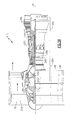
Figure 1A shows an exemplary gas turbine engine. -
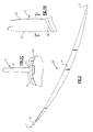
Figure 1B shows an aluminum fan blade. -
Figure 1C shows the aluminum fan blade mounted into a rotor. -
Figure 2 is a cross-sectional view along line 2-2 ofFigure 1B . -
Figure 3 shows an embodiment of this invention. -
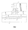
Figure 4 is another view of theFigure 3 embodiment. - A
gas turbine engine 210 is shown inFigure 1A . As shown, theengine 210 includes a fan 250 (which includes a plurality of fan blades 20), a compressor section 254 (which includes both alow pressure compressor 256 and a high pressure compressor 258), acombustor 260, and a turbine section 262 (which includes both ahigh pressure turbine 264 and a low pressure turbine 266). Thehigh pressure compressor 258 is driven, via afirst spool 268, by thehigh pressure turbine 264. Thelow pressure compressor 256 is driven, via asecond spool 270, by thelow pressure turbine 266. Also driven by thelow pressure turbine 266 are thefan blades 20 of thefan 250, which is coupled to thesecond spool 270 via agear reduction 272. - The
fan 250 delivers air intocompressor section 254. Air compressed by the compressor section is delivered intocombustor 260. Products of the combustion in the combustor pass downstream overturbine section 262. - A
fan blade 20 is illustrated inFigure 1B having anairfoil 18 extending radially outwardly from a dovetail orroot 24. A leadingedge 21 and atrailing edge 22 define the forward and rear limits of theairfoil 18. - As shown in
Figure 1C , afan rotor 16 receives thedovetail 24 to mount thefan blade 20 with theairfoil 18 extending radially outwardly. As the rotor is driven to rotate, it carries thefan blade 20 with it. -
Figure 2 shows a cross-section of thefan blade 20 at theairfoil 18. As shown, the leadingedge 21 carries a sheath orcap 37 secured to amain body 28. Themain body 28 may be formed of aluminum or various aluminum alloys. The main body may be coated with protective coatings, such as a polyurethane coating. In addition, fabric wear pads may be placed on the aluminum. Thesheath 37 may be formed of a conductive material, such as titanium, titanium alloys or appropriate metals. Thesheath 37 is thus formed of a material that is more electrically conductive than the material utilized to form the main blade body and the cover. This is due to the coating and the wear pads. Electrical charge may build up in thesheath 37. - As shown in
Figure 1C , alock ring 100 locks theblades 20 within therotor 16. - As shown in
Figure 3 , theblade 20 is mounted within therotor 16. Thelock ring 100 abuts an end of theroot 24, but also captures agrounding element 60. Thegrounding element 60 has achin 62 extending axially outwardly from amain body portion 63. The chin has a free position which would extend upwardly inFigure 3 , such that it is biased against the radially inner end ofsheath 37 in the illustrated position. Thegrounding element 60 is connected to theblade root 24 by an adhesive. Further, additional adhesive may be applied between the groundingelement 60, and the coating on the blade at the edges of the bonding element. This additional adhesive can prevent moisture or objects to penetrate into the interface between the groundingelement 60 and theblade 20. Examples of suitable adhesives include epoxy adhesive paste, such as Hysol & AF163K. - It is preferred that the adhesive be electrically insulating, or that some other electrically insulating material be utilized between the grounding element and the main body portion to prevent galvanic corrosion.
- As shown in
Figure 3 , an enlargedinner portion 64 of thegrounding element 60 extends circumferentially outwardly to mimic the shape ofroot 24. Thisportion 64 is shown to be in direct surface contact with thelock ring 100. - The
sheath 37, thegrounding element 60, thelock ring 100 and therotor 16 may all be formed of titanium or titanium alloy. As such, there is a direct ground connection between thesheath 21 to therotor 16 such that electrical charge easily dissipates. Of course, other conductive materials could be used. Non-limiting examples include copper, steel, and nickel. - As shown in
Figure 4 , thelock ring 100 sits at theenlarged portion 64. Thechin 62 is biased upwardly in this view, against a radially inner end of thesheath 37. Of course, any number of other ways of contacting thegrounding element 60 to thesheath 37, and contacting thegrounding element 60 to therotor 16 and/orlock ring 100 may be utilized. - While the disclosed embodiment provides contact between the grounding
element 63 and thelock ring 100, it is also possible to have the grounding element contact therotor 16 directly. - Although an embodiment of this invention has been disclosed, a worker of ordinary skill in this art would recognize that certain modifications would come within the scope of this invention. For that reason, the following claims should be studied to determine the true scope and content of this invention.
Claims (11)
- A fan rotor (16) for use in a gas turbine engine comprising:a rotor body having at least one slot receiving a fan blade (18);said fan blade (18) formed of a first material, and a sheath (37) positioned at a leading edge (21) of said fan blade (18), said sheath (37) being formed of a second material that is distinct from said first material, said first material being less electrically conductive than said second material; anda grounding element (63) in contact with said sheath (37), and said grounding element (63) being in contact with a rotating element (100) that rotates with said rotor, said grounding element (63) and said rotating element (100) together forming a ground path from said sheath (37) into said rotor (16).
- The fan rotor as set forth in claim 1, wherein said first material includes an outer coating that is relatively non-conductive compared to said second material.
- The fan rotor as set forth in claim 1 or 2, wherein said rotor (16) and said grounding element (63) are formed of a material that is more electrically conductive than said first material.
- The fan rotor as set forth in claim 1, 2 or 3, wherein said rotating element (100) is separate from said rotor (16) and formed of a material that is more electrically conductive than said first material.
- The fan rotor as set forth in claim 4, wherein said rotating element is a lock ring (100) which secures said fan blade within said rotor (16), said grounding element (63) contacts said lock ring (100), and said lock ring (100) contacts said rotor (16) to provide said grounding path.
- The fan rotor as set forth in claim 5, wherein said grounding element (63) sits radially inwardly of said sheath (37), and said fan blade (18) has a root (24) received in said at least one slot in said rotor (16), with said grounding element (63) extending radially inwardly along said root (24) to contact said lock ring (100).
- The fan rotor as set forth in claim 6, wherein said grounding element (63) has a chin (62) extending axially outwardly away from said rotor (16), and in contact with a radially inner portion of said sheath (37).
- The fan rotor as set forth in claim 7, wherein said chin (62) is spring biased against said radially inner portion of said sheath (37).
- The fan rotor as set forth in any of claims 5 to 8, wherein said grounding element (63) has a circumferentially enlarged radially inner portion (64) which is in contact with said lock ring (100).
- The fan rotor as set forth in any preceding claim, wherein said first material includes a protective coating formed on said blade (18), and said second material contains titanium.
- A gas turbine engine (210) comprising:a fan section (250) delivering air into a compressor section (254), said compressor section (254) delivering air into a combustor section (260), and said combustor section (260) delivering products of combustion across at least one turbine rotor, said at least one turbine rotor driving a compressor rotor, and said at least one turbine rotor also driving a fan rotor (16) of said fan section (250) through a gear reduction (272);a rotor (16) being a fan rotor as set forth in any preceding claim.
Applications Claiming Priority (1)
| Application Number | Priority Date | Filing Date | Title |
|---|---|---|---|
| US13/325,394 US9376924B2 (en) | 2011-12-14 | 2011-12-14 | Electrical grounding for fan blades |
Publications (2)
| Publication Number | Publication Date |
|---|---|
| EP2604794A1 true EP2604794A1 (en) | 2013-06-19 |
| EP2604794B1 EP2604794B1 (en) | 2017-03-08 |
Family
ID=47358379
Family Applications (1)
| Application Number | Title | Priority Date | Filing Date |
|---|---|---|---|
| EP12196763.2A Active EP2604794B1 (en) | 2011-12-14 | 2012-12-12 | Electrical Grounding for Fan Blades |
Country Status (2)
| Country | Link |
|---|---|
| US (1) | US9376924B2 (en) |
| EP (1) | EP2604794B1 (en) |
Cited By (7)
| Publication number | Priority date | Publication date | Assignee | Title |
|---|---|---|---|---|
| WO2014039419A1 (en) | 2012-09-07 | 2014-03-13 | United Technologies Corporation | Electrical grounding for blades |
| EP2905456A1 (en) * | 2014-02-07 | 2015-08-12 | United Technologies Corporation | Spinner for electrically grounding fan blades |
| EP2955326A1 (en) * | 2014-06-11 | 2015-12-16 | United Technologies Corporation | Gas turbine airfoil with a grounding element |
| EP3018289A1 (en) * | 2014-09-30 | 2016-05-11 | United Technologies Corporation | Fan blade with static dissipative coating |
| EP3040517A1 (en) * | 2014-12-29 | 2016-07-06 | United Technologies Corporation | Radial lock for fan blade sheath |
| EP3085892A1 (en) * | 2015-04-24 | 2016-10-26 | United Technologies Corporation | Fan blade, corresponding gas turbine engine and manufacturing method |
| US10087767B2 (en) | 2014-12-09 | 2018-10-02 | United Technologies Corporation | Pre-diffuser with multiple radii |
Families Citing this family (10)
| Publication number | Priority date | Publication date | Assignee | Title |
|---|---|---|---|---|
| WO2015034612A1 (en) | 2013-09-09 | 2015-03-12 | United Technologies Corporation | Fan blades and manufacture methods |
| WO2015069335A2 (en) | 2013-09-09 | 2015-05-14 | United Technologies Corporation | Fan blades and manufacture methods |
| WO2015047754A1 (en) * | 2013-09-27 | 2015-04-02 | United Technologies Corporation | Fan blade assembly |
| US10539036B2 (en) * | 2014-01-14 | 2020-01-21 | United Technologies Corporation | Abradable seal having nanolayer material |
| US9957819B2 (en) | 2014-03-28 | 2018-05-01 | United Technologies Corporation | Abrasive tip blade manufacture methods |
| US11118463B2 (en) * | 2014-04-11 | 2021-09-14 | Raytheon Technologies Corporation | Electrically grounding fan platforms |
| US9982358B2 (en) | 2014-06-04 | 2018-05-29 | United Technologies Corporation | Abrasive tip blade manufacture methods |
| EP3032041B1 (en) * | 2014-12-08 | 2019-02-06 | Ansaldo Energia Switzerland AG | Rotor heat shield and method for securing the same into a rotor assembly |
| US10450876B2 (en) | 2015-04-15 | 2019-10-22 | United Technologies Corporation | Abrasive tip blade manufacture methods |
| US10483659B1 (en) | 2018-11-19 | 2019-11-19 | United Technologies Corporation | Grounding clip for bonded vanes |
Citations (3)
| Publication number | Priority date | Publication date | Assignee | Title |
|---|---|---|---|---|
| US5123813A (en) * | 1991-03-01 | 1992-06-23 | General Electric Company | Apparatus for preloading an airfoil blade in a gas turbine engine |
| EP2353830A2 (en) * | 2010-02-05 | 2011-08-10 | United Technologies Corporation | Method of manufacturing a composite fan blade with co-cured sheath, and corresponding fan blade |
| EP2405101A2 (en) * | 2010-07-05 | 2012-01-11 | Rolls-Royce plc | A composite turbomachine blade |
Family Cites Families (3)
| Publication number | Priority date | Publication date | Assignee | Title |
|---|---|---|---|---|
| US5102302A (en) * | 1988-06-02 | 1992-04-07 | General Electric Company | Fan blade mount |
| US6004101A (en) | 1998-08-17 | 1999-12-21 | General Electric Company | Reinforced aluminum fan blade |
| US8096765B2 (en) | 2010-12-01 | 2012-01-17 | General Electric Company | Wind turbine rotor blades with enhanced lightning protection system |
-
2011
- 2011-12-14 US US13/325,394 patent/US9376924B2/en active Active
-
2012
- 2012-12-12 EP EP12196763.2A patent/EP2604794B1/en active Active
Patent Citations (3)
| Publication number | Priority date | Publication date | Assignee | Title |
|---|---|---|---|---|
| US5123813A (en) * | 1991-03-01 | 1992-06-23 | General Electric Company | Apparatus for preloading an airfoil blade in a gas turbine engine |
| EP2353830A2 (en) * | 2010-02-05 | 2011-08-10 | United Technologies Corporation | Method of manufacturing a composite fan blade with co-cured sheath, and corresponding fan blade |
| EP2405101A2 (en) * | 2010-07-05 | 2012-01-11 | Rolls-Royce plc | A composite turbomachine blade |
Cited By (13)
| Publication number | Priority date | Publication date | Assignee | Title |
|---|---|---|---|---|
| EP2893142A4 (en) * | 2012-09-07 | 2015-11-18 | United Technologies Corp | Electrical grounding for blades |
| WO2014039419A1 (en) | 2012-09-07 | 2014-03-13 | United Technologies Corporation | Electrical grounding for blades |
| EP2905456A1 (en) * | 2014-02-07 | 2015-08-12 | United Technologies Corporation | Spinner for electrically grounding fan blades |
| US9896936B2 (en) | 2014-02-07 | 2018-02-20 | United Technologies Corporation | Spinner for electrically grounding fan blades |
| EP2955326A1 (en) * | 2014-06-11 | 2015-12-16 | United Technologies Corporation | Gas turbine airfoil with a grounding element |
| US10107105B2 (en) | 2014-06-11 | 2018-10-23 | United Technologies Corporation | Fan blade grounding tab |
| EP3018289A1 (en) * | 2014-09-30 | 2016-05-11 | United Technologies Corporation | Fan blade with static dissipative coating |
| US10087767B2 (en) | 2014-12-09 | 2018-10-02 | United Technologies Corporation | Pre-diffuser with multiple radii |
| EP3040517A1 (en) * | 2014-12-29 | 2016-07-06 | United Technologies Corporation | Radial lock for fan blade sheath |
| US10287891B2 (en) | 2014-12-29 | 2019-05-14 | United Technologies Corporation | Radial lock for fan blade sheath |
| EP3085892A1 (en) * | 2015-04-24 | 2016-10-26 | United Technologies Corporation | Fan blade, corresponding gas turbine engine and manufacturing method |
| US10012238B2 (en) * | 2015-04-24 | 2018-07-03 | United Technologies Corporation | Electrostatic discharge prevention for a fan blade |
| US20160312793A1 (en) * | 2015-04-24 | 2016-10-27 | United Technologies Corporation | Electrostatic Discharge Prevention for a Fan Blade |
Also Published As
| Publication number | Publication date |
|---|---|
| US9376924B2 (en) | 2016-06-28 |
| EP2604794B1 (en) | 2017-03-08 |
| US20130156588A1 (en) | 2013-06-20 |
Similar Documents
| Publication | Publication Date | Title |
|---|---|---|
| US9376924B2 (en) | Electrical grounding for fan blades | |
| EP3121378B1 (en) | Blade or a vane for a gas turbine engine | |
| US10837295B2 (en) | Fan blade assembly | |
| EP2895699B1 (en) | Electrical grounding for blade sheath | |
| EP3018289B1 (en) | Fan blade with static dissipative coating | |
| EP3049632B1 (en) | Fan blade assembly | |
| EP3085892B1 (en) | Fan blade, gas turbine engine and method for making a fan blade | |
| EP2893142B1 (en) | Electrical grounding for blades | |
| US20160230774A1 (en) | Fan blade assembly | |
| EP2900931B1 (en) | Fan blade and grounding element, corresponding rotor and gas turbine engine | |
| US9297272B2 (en) | Grounding for fan blades on an underblade spacer | |
| EP2905456B1 (en) | Fan assembly for a gas turbine | |
| EP2930306B1 (en) | Gas turbine engine fan with discrete platforms for electrically grounding sheaths of fan airfoils | |
| WO2015047949A1 (en) | Fan blade assembly |
Legal Events
| Date | Code | Title | Description |
|---|---|---|---|
| PUAI | Public reference made under article 153(3) epc to a published international application that has entered the european phase |
Free format text: ORIGINAL CODE: 0009012 |
|
| AK | Designated contracting states |
Kind code of ref document: A1 Designated state(s): AL AT BE BG CH CY CZ DE DK EE ES FI FR GB GR HR HU IE IS IT LI LT LU LV MC MK MT NL NO PL PT RO RS SE SI SK SM TR |
|
| AX | Request for extension of the european patent |
Extension state: BA ME |
|
| 17P | Request for examination filed |
Effective date: 20131213 |
|
| RBV | Designated contracting states (corrected) |
Designated state(s): AL AT BE BG CH CY CZ DE DK EE ES FI FR GB GR HR HU IE IS IT LI LT LU LV MC MK MT NL NO PL PT RO RS SE SI SK SM TR |
|
| 17Q | First examination report despatched |
Effective date: 20140922 |
|
| RAP1 | Party data changed (applicant data changed or rights of an application transferred) |
Owner name: UNITED TECHNOLOGIES CORPORATION |
|
| GRAP | Despatch of communication of intention to grant a patent |
Free format text: ORIGINAL CODE: EPIDOSNIGR1 |
|
| INTG | Intention to grant announced |
Effective date: 20161028 |
|
| GRAS | Grant fee paid |
Free format text: ORIGINAL CODE: EPIDOSNIGR3 |
|
| GRAA | (expected) grant |
Free format text: ORIGINAL CODE: 0009210 |
|
| AK | Designated contracting states |
Kind code of ref document: B1 Designated state(s): AL AT BE BG CH CY CZ DE DK EE ES FI FR GB GR HR HU IE IS IT LI LT LU LV MC MK MT NL NO PL PT RO RS SE SI SK SM TR |
|
| REG | Reference to a national code |
Ref country code: GB Ref legal event code: FG4D |
|
| REG | Reference to a national code |
Ref country code: CH Ref legal event code: EP Ref country code: AT Ref legal event code: REF Ref document number: 873714 Country of ref document: AT Kind code of ref document: T Effective date: 20170315 |
|
| REG | Reference to a national code |
Ref country code: IE Ref legal event code: FG4D |
|
| REG | Reference to a national code |
Ref country code: DE Ref legal event code: R096 Ref document number: 602012029527 Country of ref document: DE |
|
| REG | Reference to a national code |
Ref country code: LT Ref legal event code: MG4D |
|
| REG | Reference to a national code |
Ref country code: NL Ref legal event code: MP Effective date: 20170308 Ref country code: DE Ref legal event code: R082 Ref document number: 602012029527 Country of ref document: DE Representative=s name: SCHMITT-NILSON SCHRAUD WAIBEL WOHLFROM PATENTA, DE |
|
| PG25 | Lapsed in a contracting state [announced via postgrant information from national office to epo] |
Ref country code: NO Free format text: LAPSE BECAUSE OF FAILURE TO SUBMIT A TRANSLATION OF THE DESCRIPTION OR TO PAY THE FEE WITHIN THE PRESCRIBED TIME-LIMIT Effective date: 20170608 Ref country code: GR Free format text: LAPSE BECAUSE OF FAILURE TO SUBMIT A TRANSLATION OF THE DESCRIPTION OR TO PAY THE FEE WITHIN THE PRESCRIBED TIME-LIMIT Effective date: 20170609 Ref country code: LT Free format text: LAPSE BECAUSE OF FAILURE TO SUBMIT A TRANSLATION OF THE DESCRIPTION OR TO PAY THE FEE WITHIN THE PRESCRIBED TIME-LIMIT Effective date: 20170308 Ref country code: HR Free format text: LAPSE BECAUSE OF FAILURE TO SUBMIT A TRANSLATION OF THE DESCRIPTION OR TO PAY THE FEE WITHIN THE PRESCRIBED TIME-LIMIT Effective date: 20170308 Ref country code: FI Free format text: LAPSE BECAUSE OF FAILURE TO SUBMIT A TRANSLATION OF THE DESCRIPTION OR TO PAY THE FEE WITHIN THE PRESCRIBED TIME-LIMIT Effective date: 20170308 |
|
| REG | Reference to a national code |
Ref country code: AT Ref legal event code: MK05 Ref document number: 873714 Country of ref document: AT Kind code of ref document: T Effective date: 20170308 |
|
| PG25 | Lapsed in a contracting state [announced via postgrant information from national office to epo] |
Ref country code: RS Free format text: LAPSE BECAUSE OF FAILURE TO SUBMIT A TRANSLATION OF THE DESCRIPTION OR TO PAY THE FEE WITHIN THE PRESCRIBED TIME-LIMIT Effective date: 20170308 Ref country code: BG Free format text: LAPSE BECAUSE OF FAILURE TO SUBMIT A TRANSLATION OF THE DESCRIPTION OR TO PAY THE FEE WITHIN THE PRESCRIBED TIME-LIMIT Effective date: 20170608 Ref country code: LV Free format text: LAPSE BECAUSE OF FAILURE TO SUBMIT A TRANSLATION OF THE DESCRIPTION OR TO PAY THE FEE WITHIN THE PRESCRIBED TIME-LIMIT Effective date: 20170308 Ref country code: ES Free format text: LAPSE BECAUSE OF FAILURE TO SUBMIT A TRANSLATION OF THE DESCRIPTION OR TO PAY THE FEE WITHIN THE PRESCRIBED TIME-LIMIT Effective date: 20170308 Ref country code: SE Free format text: LAPSE BECAUSE OF FAILURE TO SUBMIT A TRANSLATION OF THE DESCRIPTION OR TO PAY THE FEE WITHIN THE PRESCRIBED TIME-LIMIT Effective date: 20170308 |
|
| PG25 | Lapsed in a contracting state [announced via postgrant information from national office to epo] |
Ref country code: NL Free format text: LAPSE BECAUSE OF FAILURE TO SUBMIT A TRANSLATION OF THE DESCRIPTION OR TO PAY THE FEE WITHIN THE PRESCRIBED TIME-LIMIT Effective date: 20170308 |
|
| PG25 | Lapsed in a contracting state [announced via postgrant information from national office to epo] |
Ref country code: EE Free format text: LAPSE BECAUSE OF FAILURE TO SUBMIT A TRANSLATION OF THE DESCRIPTION OR TO PAY THE FEE WITHIN THE PRESCRIBED TIME-LIMIT Effective date: 20170308 Ref country code: CZ Free format text: LAPSE BECAUSE OF FAILURE TO SUBMIT A TRANSLATION OF THE DESCRIPTION OR TO PAY THE FEE WITHIN THE PRESCRIBED TIME-LIMIT Effective date: 20170308 Ref country code: SK Free format text: LAPSE BECAUSE OF FAILURE TO SUBMIT A TRANSLATION OF THE DESCRIPTION OR TO PAY THE FEE WITHIN THE PRESCRIBED TIME-LIMIT Effective date: 20170308 Ref country code: AT Free format text: LAPSE BECAUSE OF FAILURE TO SUBMIT A TRANSLATION OF THE DESCRIPTION OR TO PAY THE FEE WITHIN THE PRESCRIBED TIME-LIMIT Effective date: 20170308 Ref country code: RO Free format text: LAPSE BECAUSE OF FAILURE TO SUBMIT A TRANSLATION OF THE DESCRIPTION OR TO PAY THE FEE WITHIN THE PRESCRIBED TIME-LIMIT Effective date: 20170308 Ref country code: IT Free format text: LAPSE BECAUSE OF FAILURE TO SUBMIT A TRANSLATION OF THE DESCRIPTION OR TO PAY THE FEE WITHIN THE PRESCRIBED TIME-LIMIT Effective date: 20170308 |
|
| PG25 | Lapsed in a contracting state [announced via postgrant information from national office to epo] |
Ref country code: PL Free format text: LAPSE BECAUSE OF FAILURE TO SUBMIT A TRANSLATION OF THE DESCRIPTION OR TO PAY THE FEE WITHIN THE PRESCRIBED TIME-LIMIT Effective date: 20170308 Ref country code: PT Free format text: LAPSE BECAUSE OF FAILURE TO SUBMIT A TRANSLATION OF THE DESCRIPTION OR TO PAY THE FEE WITHIN THE PRESCRIBED TIME-LIMIT Effective date: 20170710 Ref country code: SM Free format text: LAPSE BECAUSE OF FAILURE TO SUBMIT A TRANSLATION OF THE DESCRIPTION OR TO PAY THE FEE WITHIN THE PRESCRIBED TIME-LIMIT Effective date: 20170308 Ref country code: IS Free format text: LAPSE BECAUSE OF FAILURE TO SUBMIT A TRANSLATION OF THE DESCRIPTION OR TO PAY THE FEE WITHIN THE PRESCRIBED TIME-LIMIT Effective date: 20170708 |
|
| REG | Reference to a national code |
Ref country code: DE Ref legal event code: R097 Ref document number: 602012029527 Country of ref document: DE |
|
| PLBE | No opposition filed within time limit |
Free format text: ORIGINAL CODE: 0009261 |
|
| STAA | Information on the status of an ep patent application or granted ep patent |
Free format text: STATUS: NO OPPOSITION FILED WITHIN TIME LIMIT |
|
| PG25 | Lapsed in a contracting state [announced via postgrant information from national office to epo] |
Ref country code: DK Free format text: LAPSE BECAUSE OF FAILURE TO SUBMIT A TRANSLATION OF THE DESCRIPTION OR TO PAY THE FEE WITHIN THE PRESCRIBED TIME-LIMIT Effective date: 20170308 |
|
| 26N | No opposition filed |
Effective date: 20171211 |
|
| PG25 | Lapsed in a contracting state [announced via postgrant information from national office to epo] |
Ref country code: SI Free format text: LAPSE BECAUSE OF FAILURE TO SUBMIT A TRANSLATION OF THE DESCRIPTION OR TO PAY THE FEE WITHIN THE PRESCRIBED TIME-LIMIT Effective date: 20170308 |
|
| REG | Reference to a national code |
Ref country code: CH Ref legal event code: PL |
|
| REG | Reference to a national code |
Ref country code: IE Ref legal event code: MM4A |
|
| PG25 | Lapsed in a contracting state [announced via postgrant information from national office to epo] |
Ref country code: LU Free format text: LAPSE BECAUSE OF NON-PAYMENT OF DUE FEES Effective date: 20171212 Ref country code: MT Free format text: LAPSE BECAUSE OF NON-PAYMENT OF DUE FEES Effective date: 20171212 |
|
| REG | Reference to a national code |
Ref country code: FR Ref legal event code: ST Effective date: 20180831 |
|
| REG | Reference to a national code |
Ref country code: BE Ref legal event code: MM Effective date: 20171231 |
|
| PG25 | Lapsed in a contracting state [announced via postgrant information from national office to epo] |
Ref country code: FR Free format text: LAPSE BECAUSE OF NON-PAYMENT OF DUE FEES Effective date: 20180102 Ref country code: IE Free format text: LAPSE BECAUSE OF NON-PAYMENT OF DUE FEES Effective date: 20171212 |
|
| PG25 | Lapsed in a contracting state [announced via postgrant information from national office to epo] |
Ref country code: BE Free format text: LAPSE BECAUSE OF NON-PAYMENT OF DUE FEES Effective date: 20171231 Ref country code: LI Free format text: LAPSE BECAUSE OF NON-PAYMENT OF DUE FEES Effective date: 20171231 Ref country code: CH Free format text: LAPSE BECAUSE OF NON-PAYMENT OF DUE FEES Effective date: 20171231 |
|
| PG25 | Lapsed in a contracting state [announced via postgrant information from national office to epo] |
Ref country code: HU Free format text: LAPSE BECAUSE OF FAILURE TO SUBMIT A TRANSLATION OF THE DESCRIPTION OR TO PAY THE FEE WITHIN THE PRESCRIBED TIME-LIMIT; INVALID AB INITIO Effective date: 20121212 Ref country code: MC Free format text: LAPSE BECAUSE OF FAILURE TO SUBMIT A TRANSLATION OF THE DESCRIPTION OR TO PAY THE FEE WITHIN THE PRESCRIBED TIME-LIMIT Effective date: 20170308 |
|
| PG25 | Lapsed in a contracting state [announced via postgrant information from national office to epo] |
Ref country code: CY Free format text: LAPSE BECAUSE OF NON-PAYMENT OF DUE FEES Effective date: 20170308 |
|
| PG25 | Lapsed in a contracting state [announced via postgrant information from national office to epo] |
Ref country code: MK Free format text: LAPSE BECAUSE OF FAILURE TO SUBMIT A TRANSLATION OF THE DESCRIPTION OR TO PAY THE FEE WITHIN THE PRESCRIBED TIME-LIMIT Effective date: 20170308 |
|
| PG25 | Lapsed in a contracting state [announced via postgrant information from national office to epo] |
Ref country code: TR Free format text: LAPSE BECAUSE OF FAILURE TO SUBMIT A TRANSLATION OF THE DESCRIPTION OR TO PAY THE FEE WITHIN THE PRESCRIBED TIME-LIMIT Effective date: 20170308 |
|
| PG25 | Lapsed in a contracting state [announced via postgrant information from national office to epo] |
Ref country code: AL Free format text: LAPSE BECAUSE OF FAILURE TO SUBMIT A TRANSLATION OF THE DESCRIPTION OR TO PAY THE FEE WITHIN THE PRESCRIBED TIME-LIMIT Effective date: 20170308 |
|
| REG | Reference to a national code |
Ref country code: DE Ref legal event code: R081 Ref document number: 602012029527 Country of ref document: DE Owner name: RAYTHEON TECHNOLOGIES CORPORATION (N.D.GES.D.S, US Free format text: FORMER OWNER: UNITED TECHNOLOGIES CORPORATION, FARMINGTON, CONN., US Ref country code: DE Ref legal event code: R081 Ref document number: 602012029527 Country of ref document: DE Owner name: RTX CORPORATION (N.D.GES.D. STAATES DELAWARE),, US Free format text: FORMER OWNER: UNITED TECHNOLOGIES CORPORATION, FARMINGTON, CONN., US |
|
| P01 | Opt-out of the competence of the unified patent court (upc) registered |
Effective date: 20230520 |
|
| REG | Reference to a national code |
Ref country code: DE Ref legal event code: R081 Ref document number: 602012029527 Country of ref document: DE Owner name: RTX CORPORATION (N.D.GES.D. STAATES DELAWARE),, US Free format text: FORMER OWNER: RAYTHEON TECHNOLOGIES CORPORATION (N.D.GES.D.STAATES DELAWARE), ARLINGTON, VA, US |
|
| PGFP | Annual fee paid to national office [announced via postgrant information from national office to epo] |
Ref country code: DE Payment date: 20251126 Year of fee payment: 14 |
|
| PGFP | Annual fee paid to national office [announced via postgrant information from national office to epo] |
Ref country code: GB Payment date: 20251120 Year of fee payment: 14 |