EP2604568A1 - Combined lifting beam arrangement for wind turbine parts - Google Patents
Combined lifting beam arrangement for wind turbine parts Download PDFInfo
- Publication number
- EP2604568A1 EP2604568A1 EP11193562.3A EP11193562A EP2604568A1 EP 2604568 A1 EP2604568 A1 EP 2604568A1 EP 11193562 A EP11193562 A EP 11193562A EP 2604568 A1 EP2604568 A1 EP 2604568A1
- Authority
- EP
- European Patent Office
- Prior art keywords
- interface
- beam arrangement
- wind turbine
- lifting beam
- tower wall
- Prior art date
- Legal status (The legal status is an assumption and is not a legal conclusion. Google has not performed a legal analysis and makes no representation as to the accuracy of the status listed.)
- Granted
Links
- 230000008878 coupling Effects 0.000 claims abstract description 34
- 238000010168 coupling process Methods 0.000 claims abstract description 34
- 238000005859 coupling reaction Methods 0.000 claims abstract description 34
- 238000000034 method Methods 0.000 claims abstract description 30
- 238000009434 installation Methods 0.000 description 20
- 230000008859 change Effects 0.000 description 5
- 238000010586 diagram Methods 0.000 description 3
- 239000000463 material Substances 0.000 description 3
- XEEYBQQBJWHFJM-UHFFFAOYSA-N Iron Chemical compound [Fe] XEEYBQQBJWHFJM-UHFFFAOYSA-N 0.000 description 2
- 229910000831 Steel Inorganic materials 0.000 description 2
- 230000008901 benefit Effects 0.000 description 2
- 238000010276 construction Methods 0.000 description 2
- 230000005484 gravity Effects 0.000 description 2
- 230000003993 interaction Effects 0.000 description 2
- 238000012423 maintenance Methods 0.000 description 2
- 230000008569 process Effects 0.000 description 2
- 239000010959 steel Substances 0.000 description 2
- 230000003213 activating effect Effects 0.000 description 1
- 230000006978 adaptation Effects 0.000 description 1
- 210000000078 claw Anatomy 0.000 description 1
- 230000003247 decreasing effect Effects 0.000 description 1
- 230000001419 dependent effect Effects 0.000 description 1
- 230000000694 effects Effects 0.000 description 1
- 239000000446 fuel Substances 0.000 description 1
- 229910052742 iron Inorganic materials 0.000 description 1
- 230000007246 mechanism Effects 0.000 description 1
- 239000002184 metal Substances 0.000 description 1
- 229910052751 metal Inorganic materials 0.000 description 1
- 230000004048 modification Effects 0.000 description 1
- 238000012986 modification Methods 0.000 description 1
- 238000004904 shortening Methods 0.000 description 1
Images


Classifications
-
- B—PERFORMING OPERATIONS; TRANSPORTING
- B66—HOISTING; LIFTING; HAULING
- B66C—CRANES; LOAD-ENGAGING ELEMENTS OR DEVICES FOR CRANES, CAPSTANS, WINCHES, OR TACKLES
- B66C1/00—Load-engaging elements or devices attached to lifting or lowering gear of cranes or adapted for connection therewith for transmitting lifting forces to articles or groups of articles
- B66C1/10—Load-engaging elements or devices attached to lifting or lowering gear of cranes or adapted for connection therewith for transmitting lifting forces to articles or groups of articles by mechanical means
- B66C1/108—Load-engaging elements or devices attached to lifting or lowering gear of cranes or adapted for connection therewith for transmitting lifting forces to articles or groups of articles by mechanical means for lifting parts of wind turbines
Definitions
- the present invention describes a combined lifting beam arrangement for handling wind turbine parts, in particular to a combined lifting beam arrangement for handling tower wall portions and a nacelle and/or a hub and/or a generator of a wind turbine without changing the lifting beam arrangement between two lifting operations.
- the present invention further describes a method of handling different wind turbine parts using the same combined lifting beam arrangement.
- wind turbines are constructed as hollow steel towers made of prefabricated tower portions.
- the tower is constructed or assembled by successively lifting and placing a series of tower wall portions on top of each other, whereby the lowest tower wall portion is mounted on a foundation, usually made of concrete, and includes access means such as a doorway to later allow access for a maintenance crew.
- the tower wall portions become successively smaller in diameter towards the top of the tower.
- Neighbouring tower wall portions are connected by means of fasteners such as construction bolts inserted into connection holes in the end flanges.
- connection holes of the neighbouring portions are positioned such that connection holes in the top flange of the lower tower wall portion match the connection holes in the bottom flange of the upper tower wall portion.
- a number of lifting fittings usually at least two - is mounted to one of the end flanges of the portion, usually the upper flange, and a cable is connected to the lifting fittings to allow a crane to hoist the portion onto the previously assembled partial tower wall portion.
- the successive tower wall portions generally differ in diameter owing to the overall conical tower shape, and the spacings between the connection holes therefore also differ.
- prior art lifting techniques have required multiple lifting fittings, sometimes even a specific lifting fitting for each tower section.
- a lifting technique for the installation of a nacelle, hub and generator at the top of a wind turbine tower are also known in the art.
- individual lifting brackets or sling systems are used for handling these wind turbine parts.
- a special sling system is connected to a nacelle or hub or generator to lift it into the position at the top of the tower, wherein the sling system comprises a number of slings for holding the nacelle or the hub or the generator at special coupling means.
- the object of the invention is achieved by the combined lifting beam arrangement according to claim 1, and by the method of handling wind turbine parts according to claim 11.
- the combined lifting beam arrangement according to the invention is specifically adjusted for handling wind turbine parts, in particular wind turbine parts having different engaging structures, such as tower wall parts, nacelles, hubs, or generators of a wind turbine.
- the combined lifting beam arrangement comprises a beam with a connecting element.
- the connecting element is realized to be connected to the lifting device directly or via a coupling element such as a hook liftable by the lifting device.
- the beam may be connectable to the lifting device by means of the connecting element, such as a pad eye, a loop, a grommet or the like.
- the beam may be connectable to the connecting element in a detachable manner, for example for facilitating the transport, maintenance work of the lifting beam arrangement or the like.
- the lifting beam arrangement further comprises a first interface for a first engaging structure and a second interface for a second engaging structure which are provided at the beam, preferably at different positions so that they cannot interfere with each other.
- additional interfaces for a third or fourth or even more engaging structures may be present at the beam without deviating from the invention.
- Interface means in the sense of the present invention, any connecting means adapted to a specific engaging structure of a wind turbine part such as of the tower wall portions, the nacelle, the hub, the generator or the like.
- engaging structure means that the element to be lifted has a portion into which a holding member of the interface can be engaged by means of a structural engagement, e.g.
- the first interface has a number of first holding members adapted for an engagement of the lifting beam arrangement with a tower wall portion of a wind turbine and the second interface has a number of second holding members adapted for an engagement of the lifting beam arrangement with coupling elements of a nacelle and/or a hub and/or a generator of a wind turbine.
- a "holding member” can be any member suitable for holding the respective wind turbine part with a specific engaging structure such as a holding tool having a corresponding structural configuration.
- the first and second holding members may comprise portions for locking the first and/or second holding members at the beam.
- they can be locked at the beam in a releasable manner in one preferred position or may be slidable at the beam along its longitudinal direction.
- an adaptation of the position of the first holding members to different diameters of the tower wall portions or of the second holding members to the geometry of the other wind turbine parts is possible.
- one or more bolts may be provided which may be inserted into one or more holes in the first holding member and/or in the second holding member and/or in the beam.
- the first and/or the second holding members may be integrally provided in the beam.
- the above-described combined lifting beam arrangement may be used in the method according to the invention.
- the method of handling wind turbine parts according to the invention, in particular parts having different engaging structures comprises the following steps:
- the method according to the invention is particularly straightforward and fast. Since no individual slings and lifting brackets are used for handling of wind turbine parts having different engaging structures and the same combined lifting beam arrangement is used for handling the tower wall portions and the nacelle and/or the hub and/or the generator, the main lifting device, e.g. a crane, can go directly from the tower top to the nacelle after transferring or installing the top tower wall portion. "Transferring" in the sense of the invention means any handling procedure used during installation, transportation or loading of wind turbine parts. Therefore, the method according to the invention reduces not only crane time and human resources needed for handling operations of wind turbine parts, but also reduces the overall costs.
- the combined lifting beam arrangement according to the invention may preferably be constructed to handle wind turbine parts having different engaging structures, such as tower wall portions with different diameters or a nacelle or hub or generator of a wind turbine.
- the beam of the combined lifting beam arrangement may have an elongated shape being extendable in its longitudinal direction.
- the beam may for example be manufactured from a rigid material such as a metal, in particular iron or steel.
- the beam may also be represented by a bar, a rod, a pole or the like.
- the length of the beam (along its longitudinal direction) may range between about 2 m and 20 m, in particular between about 4 m and 10 m, more preferably between about 5 and 8 m.
- the length of the beam may depend on the diameter or the length of the parts of a wind turbine to be lifted with the same lifting beam arrangement such as a tower wall portion, a nacelle or the like.
- the length of the beam may be larger than the diameter of the largest tower wall portion and/or the length of the other parts to be lifted.
- the beam may have a specific cross-sectional shape for providing a sufficient stiffness to withstand forces acting on the holding members and being transferred to the beam, when the tower wall portion and/or the other parts of a wind turbine such as the nacelle, the hub, or the generator are engaged by the interfaces.
- the beam may have a cross-sectional shape such as a T-shape, H-shape, I-shape, U-shape, O-shape or any other shape providing a sufficient stiffness for holding and lifting a wind turbine part such as a tower wall portion or a nacelle or the like.
- the first interface comprises an automatic hook system.
- An automatic hook system may have a number of (in particular 2, 3, 4 or even more) locking elements for locking the tower wall portions at different positions.
- An example of such a locking element is a grabbing element or a claw which can grab the top flange of a tower portion at different positions, in particular at two opposite positions at the inner perimeter of the tower top flange.
- the first interface in particular the automatic hook system of the first interface, may further comprise a manually or automatically driven actuator moving at least one of the holding members.
- actuators are hydraulic or pneumatic or electrical actuators like a piston, a motor, a magnetic valve, or the like. Those actuators may be driven by a battery or a fuel-driven generator.
- the actuator is a remote controlled (for example by means of radio frequency) actuator which can be controlled from a site different from the place of the actuator.
- the remote control may be handled from any position suitable to control the installation of a wind turbine, for example from the ground, a ship, a crane or the like.
- Such an actuator may for example bring locking elements of an automatic hook system in engagement with the tower wall portion at a specific engagement position.
- at least one of the first holding members comprises a locking element adapted for engaging with an engaging structure of a tower wall portion.
- the locking elements may in an exemplified embodiment be adapted for engaging with a flange arranged at an end, e.g. the top, of a tower wall portion during the handling operation.
- the locking elements may be mechanically displaced from one inner position to one outer position, e.g. by activating two or more joined rods by an actuating means.
- the locking elements are positioned behind at least a part of a bracket of an end part of a tower wall portion or a rim or a flange protruding from the tower wall portion inwards.
- the locking elements and thereby the combined lifting beam arrangement may be locked or secured to the tower wall portion from falling down.
- the locking of the tower wall portion to the first holding member may be stably achieved by increasing the distance between the locking elements, involving clamping radial outer portions of the locking elements between inner surfaces of the tower wall portion.
- the second holding member comprises a number of, preferably essentially vertical, wires which can be used for handling and lifting a nacelle or a hub or a generator.
- wires other flexible lifting means such as, e.g., slings, ropes, chains, or more stiff lifting means such as, e.g. plates, beams or frames, can be used.
- stiff lifting means may be useful to withstand the weight or the structure of the turbine part.
- frames or plates they can be combined with more flexible lifting means to provide a second holding member adjusted to a specific part of a wind turbine.
- a frame for a nacelle, hub or generator made of a rigid material can be connected by means of a chain or a sling to the beam.
- the holding members such as slings or wires are positioned such that they are in a nearly vertical position during operation, that means that the coupling means of the wind turbine part and the holding member connection with the combined lifting beam arrangement are vertically aligned
- the forces in the lifting points i.e. the coupling means
- the both ends of the slings are positioned at the beam in a position that each of the ends will be essentially vertical, i.e. up to an angle of about 1 to 15 degree, preferably between about 2 to 10 degree, more preferably between about 4 to 8 degree, especially about 6 degree.
- connection points with the beam depends thus on the width of or the distance of the coupling means at the nacelle or other wind turbine parts to be lifted. Therefore, it is preferable that the second holding members may be movably connected to the beam so that the distance between two or three connection points at the beam can be manually or automatically varied.
- a further advantage of vertical second holding members e.g. vertical slings, is that less force is applied to the lifting points and thus smaller slings can be used, for example slings made of wires with a smaller diameter than conventional wires. Hence, this would reduce the amount of material and thus lowers the costs and the weight of the second holding members and the whole combined lifting beam arrangement. Moreover, smaller and vertical slings may be easier to handle for the technicians.
- the inventive combined lifting beam arrangement according to the invention may have one or two control line coupling means for connecting control lines for rotating the lifting beam arrangement and the wind turbine part hanging thereon.
- the control lines are attached to the lifting beam arrangement and not to the tower wall portion, nacelle, hub or generator, the wind turbine parts can be freely rotated during the handling operation.
- the combined lifting beam arrangement further may be designed to have a pitch system for adjusting a pitch of the beam from a horizontal position into a position angular to the horizontal position, preferably during operation of the lifting beam arrangement.
- the pitch is the deviation of the main horizontal axis of the beam from the horizontal position. If the beam and the main horizontal axis of the lifted wind turbine part are nearly in a parallel position, the pitch may also be the deviation of the main axis of the wind turbine part from the horizontal position.
- the pitch system preferably comprises at least two pitch system connecting members connecting the pitch system with the beam at two or more different coupling positions in a longitudinal direction of the beam.
- the pitch system connecting members comprise two or more wires connecting the lifting device (e.g. a hook of a crane) with two or more different coupling positions at the beam for holding the beam in a working position.
- the working position is generally horizontal in its basic modus, while the beam may be in a pitch modus by changing the length of at least one of the wires.
- the wires i.e. of the pitch system connecting members
- one, two or more of the wires may be provided with a winch to adjust the pitch (that means the angle between the beam and the horizontal position) of the lifting beam arrangement.
- the winches are provided movable in longitudinal direction at the beam.
- the pitch of the lifting beam arrangement may be adjusted by moving the position of one or more of at least two coupling positions at which at least two pitch system connecting wires are provided for connecting the pitch system with the beam in a longitudinal direction of the beam. If, for example, moving the position of one of the coupling positions to a different position nearer to the end of the beam the leverage force on the beam is changed.
- the pitch of the wind turbine parts lifted can be changed by individually changing the length of the first and second holding members connecting the beam with the wind turbine part lifted. This change of the length can also be made by means of winches provided in the first or second holding members.
- the first interface comprises parts of the second interface and/or the second interface comprises parts of the first interface.
- the holding members of the first interface can be used together with or instead of some of the holding members of the second interface.
- the slings for nacelle or generator lifting can be used as additional holding members during the handling or installation of the tower wall portions.
- the tower wall portion can be supported by the second holding members. That means, e.g., the wires can be locked into separate coupling elements at the outside of the tower wall portion in order to stabilize the position of the tower wall portion during installation.
- the wires constituting the second holding members may be used as control lines during the tower installation instead of separate control lines or together with separate control lines provided at the combined lifting beam arrangement.
- the combined lifting beam arrangement comprises a remote control system realized to control parts of the first and/or the second interface.
- a remote control system realized to control parts of the first and/or the second interface.
- the remote controlled locking and releasing of the interfaces, in particular the holding members reduces installation time because the technician does not need to change the position and, in particular, the right surveillance eliminates the demand for having technicians in the tower when hooking on and off the tower. This will also allow the lifting apparatus such as the main crane, to be released faster to grab the nacelle, the hub or the generator.
- the above described combined lifting beam arrangement may advantageously be used in the method of handling wind turbine parts according to the invention because it is specifically adapted for tower wall portion lifting and nacelle lifting and, optionally, hub or generator lifting.
- a change of the lifting beams during the installation of a wind turbine is not necessary and the main crane can start nacelle installation subsequently after having installed the top of the wind turbine tower portions.
- the time for installation can be significantly reduced with this combined lifting beam arrangement.
- At least one of the engaging and/or transferring steps is controlled by remote control.
- an automatic hook system is used for hooking on and off the tower wall portions. Then, the crane may go directly to hook on the nacelle without any change in the lifting beam arrangement after installation of the tower wall portions.
- the second holding members are then engaged into the respective engaging structures to lift the nacelle.
- an automatic system is used with the second holding members. Then, the first and the second interfaces can be remote controlled from a position outside the tower, for example on the ground or in a crane. If, for example, the first and/or the second interface is controlled by remote control mechanisms, installation time can be significantly decreased and the installation procedure can be made safer because it is not demanded that a technician need to climb up and down the tower to disengage the wind turbine parts.
- a pitch control step for adjusting a pitch of a beam of the lifting beam arrangement from a horizontal position into a position angular to the horizontal position comprises changing the length of one of at least two pitch system connecting members connecting the pitch system with the beam at two or more different coupling positions in a longitudinal direction of the beam.
- the working position of the lifting beam arrangement is generally horizontal in a basic modus.
- the beam may be in a pitch modus by changing the length of at least one of the pitch system connecting members such as wires connecting the beam with the connecting element provided for connecting the lifting beam arrangement with a lifting device.
- the length of the wires i.e. of the pitch system connecting members
- one, two or more of the wires may be provided with a winch to adjust the pitch (that means the angle between the beam and the horizontal position) of the lifting beam arrangement.
- the control step comprises moving the position of one or more of at least two coupling positions at which at least two pitch system connecting wires are provided for connecting the pitch system with the beam in a longitudinal direction of the beam.
- the winches are provided movable in longitudinal direction at the beam.
- the pitch of the lifting beam arrangement may be adjusted by moving the position of one or more of at least two coupling positions at which at least two pitch system connecting wires are provided for connecting the pitch system with the beam in a longitudinal direction of the beam. If, for example, moving the position of one of the coupling positions to a different position nearer to the end of the beam the leverage force on the beam is changed and a desired pitch can be foreseen.
- Fig. 1 shows a side view of an embodiment of a combined lifting beam arrangement 1
- Fig. 2 shows a sectional view of the combined lifting beam arrangement of Fig. 1
- the combined lifting beam arrangement comprises a beam 2, a connecting element 3, and a first interface 4 with first holding members 5, locking members 8, and an actuator 13.
- the Figures further show a second interface 6 with second holding members 7.
- control line coupling means 9, control lines 10, pitch system connecting members 23, and coupling positions 24 as well as a tower 11 with an inner flange 12 are shown as well.
- the combined lifting beam arrangement 1 consists of the beam 2 which extends in its longitudinal direction such that the two interfaces do not interfere with each other, but provides enough space for providing both thereon.
- the total length depends on the parts to be lifted and is longer than the biggest distance of the lifting points (coupling points at the wind turbine parts to be lifted) at the biggest tower wall portion or the biggest other wind turbine part such as the nacelle, the hub or the generator.
- the distance of the lifting points of a nacelle are bigger than the inner diameter of a tower wall portion so that the first interface 4 is provided in the middle of the longitudinal direction of the beam 2 and the second interface 6 is provided around the first interface 4 or closer to the ends of the beam 2 as shown in Figures 1 and 2 .
- the connecting element 3 is provided at the top of the beam 2 and consists of a pitch system consisting of two wires 23 each of which is fixed to the upper side of the beam 2 in a middle position close to the gravity centre of the beam 2.
- the wires 23 extend vertically to a point at which a hook can be locked and then each of them goes to one of the outer ends of the beam 2.
- the wires 23 are connected to winches (not shown) provided at coupling positions 24.
- the winches are useful to change the length of the wires 23 for adjusting the pitch of the beam, if necessary. If, for example, the right wire as the right pitch system connecting member 23 is shortened the right-hand side of the beam will be raised up and the beam 2 will be in a pitched position. The same can be made by prolonging the left-hand wire as the left pitch system connecting member 23. In a similar manner, the left-hand side of the beam 2 can be varied by changing the length of the right or the left wire 23 of the coupling means 3.
- Fig. 2 the first interface 4 holding the tower wall portion 11 is shown.
- the first interface 4 is mounted in the middle of the beam at its side opposite to the coupling means 3.
- the tower wall portion 11 can be balanced more easily.
- the interface 4 consists of an actuator 13 and holding members 5. At the end of the holding members 5, locking portions 8 protruding behind a flange 12 of the tower wall portion 11 in a locked position are shown.
- the combined lifting beam arrangement 1 is engaged into the engaging structure, the flange 12, of the tower wall portion 11 by means of the first interface 4.
- the tower wall portion 11 can be handled, for example, be installed on a foundation or placed in a transportation vessel. It is of course possible to lift and transport any such parts at the same time from one place to another place.
- control line coupling means 9 are provided at both ends of the beam 2, at both ends of the beam 2, control line coupling means 9 are provided.
- both control line coupling means 9 are provided at a separate part of the beam 2, a so called beam-extending portion 20.
- This beam-extending portion 20 may be a fixed element or can be detachable or movable provided so that the position of the control line coupling means 9 can be varied manually and/or automatically before or during the handling operation.
- the beam-extending portion 20 may be provided as a pivoting element if the lifted wind turbine parts may hinder the control lines 10 in the straight line position.
- the control lines 10 are connected to the lifting device (not shown) such as a crane (not shown) to rotate the tower wall portion 11 into the correct position.
- the second interface 6 with the second holding members 7 is not engaged in this embodiment where the tower wall portion is lifted.
- Fig. 3 the same combined lifting beam arrangement 1 as in Fig. 1 and 2 is shown. However instead of handling and lifting a tower wall portion 11, a nacelle 15 is lifted by means of the second interface 6.
- the combined lifting beam arrangement 1 has the same parts as in Fig. 1 and 2 , while the first interface 4 is not engaged at this time.
- a nacelle 15 is held by means of two slings 7 of the second interface 6.
- the slings 7 are connected to coupling means at the nacelle which are located at the front side 16 (preferably near to the gravity centre) and in the middle of the nacelle housing 17.
- the sling 7 at the nacelle housing 17 goes through holes in the housing into the nacelle housing 17 and is connected to the inner wall of the nacelle housing 17.
- the length of the slings 7 is such that the nacelle 15 is lifted in a slightly pitched manner.
- the angel to the horizontal position is less than about 15 degree, preferably between 2 and 10 degrees, in particular about 6 degrees, while the combined lifting beam arrangement 1 is nearly in a horizontal position. If the desired pitch needs to be varied, this can be done by using the pitch system (not shown) as described before.
- FIG. 4 a same combined lifting beam arrangement 1 as in the Fig. 1 to 3 is shown.
- the lifted nacelle 15 is a nacelle 15 with a cooler 18 at its rear side.
- the sling 7 at the front side 17 of the nacelle 15 comprises one wire 7 which is connected to a coupling means (not shown) at the middle of the front side 17 of the nacelle.
- the other wire 7 is constituted of two separate wires which go to coupling means inside the nacelle housing 17 wherein one is provided at the left and the other at the right side of the nacelle housing 17 to achieve a stable lifting condition.
- the combined lifting beam arrangement 1 is advantageous because any wind turbine parts, even though they have different engaging structures, such as a tower wall portion or a nacelle can be lifted without changing the lifting beam arrangement between two lifting procedures. Thereby the overall time of installation of a wind turbine, especially in an offshore wind farm, can be reduced.
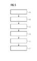
- Fig. 5 shows a block diagram of the method of the invention.
- step A a number of first holding members 5 of a first interface portion 4 of a combined lifting beam arrangement 1 are engaged into a tower wall portion 11 of a wind turbine.
- step B the tower wall portion 11 is transferred from a first location to a second location, for example from a loading vessel on a ship to a foundation of an off-shore wind power plant.
- step C the first interface 4 is disengaged from the tower wall portion 11, for example by using a remote controlled automatic hook system as described before.
- a nacelle 15 of a wind turbine is engaged by means of a number of second holding members 7 of a second interface 6 of the lifting beam arrangement 1 as described beforehand (step D).
- step E the nacelle 15 is transferred from a third location to a fourth location in step E.
- step F the second interface 6 is disengaged from the nacelle 15 by using a remote controlled automatic second interface.
- the method can be used for hub or generator installation after the nacelle has been installed (not shown).
Abstract
Description
- The present invention describes a combined lifting beam arrangement for handling wind turbine parts, in particular to a combined lifting beam arrangement for handling tower wall portions and a nacelle and/or a hub and/or a generator of a wind turbine without changing the lifting beam arrangement between two lifting operations. The present invention further describes a method of handling different wind turbine parts using the same combined lifting beam arrangement.
- Many wind turbines are constructed as hollow steel towers made of prefabricated tower portions. The tower is constructed or assembled by successively lifting and placing a series of tower wall portions on top of each other, whereby the lowest tower wall portion is mounted on a foundation, usually made of concrete, and includes access means such as a doorway to later allow access for a maintenance crew. The tower wall portions become successively smaller in diameter towards the top of the tower. Neighbouring tower wall portions are connected by means of fasteners such as construction bolts inserted into connection holes in the end flanges. For example, for a pair of tower wall portions comprising a 'lower' tower wall portion and an 'upper' tower wall portion, the connection holes of the neighbouring portions are positioned such that connection holes in the top flange of the lower tower wall portion match the connection holes in the bottom flange of the upper tower wall portion.
- To lift a tower wall portion, a number of lifting fittings - usually at least two - is mounted to one of the end flanges of the portion, usually the upper flange, and a cable is connected to the lifting fittings to allow a crane to hoist the portion onto the previously assembled partial tower wall portion. However, the successive tower wall portions generally differ in diameter owing to the overall conical tower shape, and the spacings between the connection holes therefore also differ. To accommodate these differences, prior art lifting techniques have required multiple lifting fittings, sometimes even a specific lifting fitting for each tower section.
- Alternatively, standard universal lifting brackets for mounting in the tower wall flanges by bolts were used in the prior art. After lifting and assembling a first tower wall portion to an already installed tower wall portion, the lifting bracket has to be removed from the flange of the lifted tower wall portion and mounted again to the next tower wall portion. Thus, during the unbolting process of the lifting brackets, a technician must climb to the top of the tower. In this time, the crane with the lifting bracket is still above the tower.
- In addition, the same or another technician must climb to the top of a tower wall portion for hooking it onto the lifting bracket before being handled as the tower wall portion to be installed as the next one. This procedure may be very time-consuming because of the need that technicians must hook on and hook off the tower wall portions manually.
- Several lifting techniques for the installation of a nacelle, hub and generator at the top of a wind turbine tower are also known in the art. Usually, individual lifting brackets or sling systems are used for handling these wind turbine parts. For example, a special sling system is connected to a nacelle or hub or generator to lift it into the position at the top of the tower, wherein the sling system comprises a number of slings for holding the nacelle or the hub or the generator at special coupling means.
- As the working time, i.e. the man-hours of the technicians are highly expensive for wind turbine installations and, especially, in offshore wind farms, there may be a need for shortening the time and reducing the working hours for the installation of wind turbines. It is therefore an object of the present application to provide an improved lifting beam arrangement and a method for handling wind turbine parts easier and faster.
- The object of the invention is achieved by the combined lifting beam arrangement according to claim 1, and by the method of handling wind turbine parts according to
claim 11. - The combined lifting beam arrangement according to the invention is specifically adjusted for handling wind turbine parts, in particular wind turbine parts having different engaging structures, such as tower wall parts, nacelles, hubs, or generators of a wind turbine. In order to be connectable to a lifting device such as a crane suitable for installing a wind turbine on a foundation or for loading or unloading parts thereof in or from a transportation vehicle, the combined lifting beam arrangement comprises a beam with a connecting element. The connecting element is realized to be connected to the lifting device directly or via a coupling element such as a hook liftable by the lifting device.
- The beam may be connectable to the lifting device by means of the connecting element, such as a pad eye, a loop, a grommet or the like. In particular, the beam may be connectable to the connecting element in a detachable manner, for example for facilitating the transport, maintenance work of the lifting beam arrangement or the like.
- The lifting beam arrangement according to the invention further comprises a first interface for a first engaging structure and a second interface for a second engaging structure which are provided at the beam, preferably at different positions so that they cannot interfere with each other. Of course additional interfaces for a third or fourth or even more engaging structures may be present at the beam without deviating from the invention. "Interface" means in the sense of the present invention, any connecting means adapted to a specific engaging structure of a wind turbine part such as of the tower wall portions, the nacelle, the hub, the generator or the like. The term "engaging structure" means that the element to be lifted has a portion into which a holding member of the interface can be engaged by means of a structural engagement, e.g. by engaging behind a protruding element or by a bolt-engagement, e.g. in an eye of the part to be lifted, or a frictional connection of the holding element at a friction surface of the part to be lifted. Any other engagement technique known to the skilled person in this field such as clamping techniques and so forth may be used as engaging structures.
- In order to provide a connection with specific engaging structures, the first interface has a number of first holding members adapted for an engagement of the lifting beam arrangement with a tower wall portion of a wind turbine and the second interface has a number of second holding members adapted for an engagement of the lifting beam arrangement with coupling elements of a nacelle and/or a hub and/or a generator of a wind turbine. A "holding member" can be any member suitable for holding the respective wind turbine part with a specific engaging structure such as a holding tool having a corresponding structural configuration.
- The first and second holding members may comprise portions for locking the first and/or second holding members at the beam. In particular, they can be locked at the beam in a releasable manner in one preferred position or may be slidable at the beam along its longitudinal direction. Thereby, an adaptation of the position of the first holding members to different diameters of the tower wall portions or of the second holding members to the geometry of the other wind turbine parts is possible. For locking the first holding member and/or the second holding member to the beam one or more bolts may be provided which may be inserted into one or more holes in the first holding member and/or in the second holding member and/or in the beam. Alternatively, the first and/or the second holding members may be integrally provided in the beam.
- The above-described combined lifting beam arrangement may be used in the method according to the invention. The method of handling wind turbine parts according to the invention, in particular parts having different engaging structures, comprises the following steps:
- (A) engaging a tower wall portion of a wind turbine with a number of first holding members of a first interface portion of a combined lifting beam arrangement,
- (B) transferring the tower wall portion from a first location to a second location,
- (C) disengaging the first interface from the tower wall portion,
- (D) engaging a nacelle or a hub or a generator of a wind turbine with a number of second holding members of a second interface of the lifting beam arrangement,
- (E) transferring the nacelle or the hub or the generator from a third location to a fourth location, and
- (F) disengaging the second interface from the nacelle or hub or generator.
- In contrast to prior art handling procedures, the method according to the invention is particularly straightforward and fast. Since no individual slings and lifting brackets are used for handling of wind turbine parts having different engaging structures and the same combined lifting beam arrangement is used for handling the tower wall portions and the nacelle and/or the hub and/or the generator, the main lifting device, e.g. a crane, can go directly from the tower top to the nacelle after transferring or installing the top tower wall portion. "Transferring" in the sense of the invention means any handling procedure used during installation, transportation or loading of wind turbine parts. Therefore, the method according to the invention reduces not only crane time and human resources needed for handling operations of wind turbine parts, but also reduces the overall costs.
- Particularly advantageous embodiments and features of the invention are given by the dependent claims, as revealed in the following description. Further embodiments may be derived by combining the features of the various embodiments described below, and features of the various claim categories can be combined in any appropriate manner.
- The combined lifting beam arrangement according to the invention may preferably be constructed to handle wind turbine parts having different engaging structures, such as tower wall portions with different diameters or a nacelle or hub or generator of a wind turbine. In order to be suitably adapted to handle different wind turbine parts, the beam of the combined lifting beam arrangement may have an elongated shape being extendable in its longitudinal direction. The beam may for example be manufactured from a rigid material such as a metal, in particular iron or steel. The beam may also be represented by a bar, a rod, a pole or the like. The length of the beam (along its longitudinal direction) may range between about 2 m and 20 m, in particular between about 4 m and 10 m, more preferably between about 5 and 8 m. The length of the beam may depend on the diameter or the length of the parts of a wind turbine to be lifted with the same lifting beam arrangement such as a tower wall portion, a nacelle or the like. In particular, the length of the beam may be larger than the diameter of the largest tower wall portion and/or the length of the other parts to be lifted.
- The beam may have a specific cross-sectional shape for providing a sufficient stiffness to withstand forces acting on the holding members and being transferred to the beam, when the tower wall portion and/or the other parts of a wind turbine such as the nacelle, the hub, or the generator are engaged by the interfaces. In particular, the beam may have a cross-sectional shape such as a T-shape, H-shape, I-shape, U-shape, O-shape or any other shape providing a sufficient stiffness for holding and lifting a wind turbine part such as a tower wall portion or a nacelle or the like.
- In a preferred embodiment of the combined lifting beam arrangement, the first interface comprises an automatic hook system. An automatic hook system may have a number of (in particular 2, 3, 4 or even more) locking elements for locking the tower wall portions at different positions. An example of such a locking element is a grabbing element or a claw which can grab the top flange of a tower portion at different positions, in particular at two opposite positions at the inner perimeter of the tower top flange.
- The first interface, in particular the automatic hook system of the first interface, may further comprise a manually or automatically driven actuator moving at least one of the holding members. Examples of actuators are hydraulic or pneumatic or electrical actuators like a piston, a motor, a magnetic valve, or the like. Those actuators may be driven by a battery or a fuel-driven generator. Preferably, the actuator is a remote controlled (for example by means of radio frequency) actuator which can be controlled from a site different from the place of the actuator. In particular, the remote control may be handled from any position suitable to control the installation of a wind turbine, for example from the ground, a ship, a crane or the like. Thus, an automatic engagement and disengagement of the tower wall portions during the installation or handling process is possible. This reduces working hours and is safer because a manual interaction of a technician is not demanded.
- Such an actuator may for example bring locking elements of an automatic hook system in engagement with the tower wall portion at a specific engagement position. Thus, in one embodiment of the invention, at least one of the first holding members comprises a locking element adapted for engaging with an engaging structure of a tower wall portion. Thereby, it is for example possible to bring a first locking element in engagement with the tower wall portion at a first position and to bring a second locking element in engagement with the tower wall portion at a second engagement position. Further locking elements, such as three or four locking elements may be used to stabilize the locking position during the transferring procedure.
- The locking elements may in an exemplified embodiment be adapted for engaging with a flange arranged at an end, e.g. the top, of a tower wall portion during the handling operation. The locking elements may be mechanically displaced from one inner position to one outer position, e.g. by activating two or more joined rods by an actuating means. In the outer position, the locking elements are positioned behind at least a part of a bracket of an end part of a tower wall portion or a rim or a flange protruding from the tower wall portion inwards. In particular, by increasing the distance between the locking elements the locking elements and thereby the combined lifting beam arrangement may be locked or secured to the tower wall portion from falling down. More particularly, the locking of the tower wall portion to the first holding member may be stably achieved by increasing the distance between the locking elements, involving clamping radial outer portions of the locking elements between inner surfaces of the tower wall portion.
- In another embodiment of the combined lifting beam arrangement according to the invention, the second holding member comprises a number of, preferably essentially vertical, wires which can be used for handling and lifting a nacelle or a hub or a generator. Instead of wires, other flexible lifting means such as, e.g., slings, ropes, chains, or more stiff lifting means such as, e.g. plates, beams or frames, can be used. Especially the more stiff lifting means may be useful to withstand the weight or the structure of the turbine part. In case frames or plates are used, they can be combined with more flexible lifting means to provide a second holding member adjusted to a specific part of a wind turbine. For example, a frame for a nacelle, hub or generator made of a rigid material can be connected by means of a chain or a sling to the beam.
- If the holding members such as slings or wires are positioned such that they are in a nearly vertical position during operation, that means that the coupling means of the wind turbine part and the holding member connection with the combined lifting beam arrangement are vertically aligned, the forces in the lifting points, i.e. the coupling means, may be reduced significantly in contrast to a diagonal or tilted connection between both points. Thus, if slings are used it is preferred that the both ends of the slings are positioned at the beam in a position that each of the ends will be essentially vertical, i.e. up to an angle of about 1 to 15 degree, preferably between about 2 to 10 degree, more preferably between about 4 to 8 degree, especially about 6 degree. The distance between both connection points with the beam depends thus on the width of or the distance of the coupling means at the nacelle or other wind turbine parts to be lifted. Therefore, it is preferable that the second holding members may be movably connected to the beam so that the distance between two or three connection points at the beam can be manually or automatically varied.
- A further advantage of vertical second holding members, e.g. vertical slings, is that less force is applied to the lifting points and thus smaller slings can be used, for example slings made of wires with a smaller diameter than conventional wires. Hence, this would reduce the amount of material and thus lowers the costs and the weight of the second holding members and the whole combined lifting beam arrangement. Moreover, smaller and vertical slings may be easier to handle for the technicians.
- In a further embodiment, the inventive combined lifting beam arrangement according to the invention may have one or two control line coupling means for connecting control lines for rotating the lifting beam arrangement and the wind turbine part hanging thereon. As the control lines are attached to the lifting beam arrangement and not to the tower wall portion, nacelle, hub or generator, the wind turbine parts can be freely rotated during the handling operation. In addition, there is no need of attaching or removing the control lines when the nacelle, the hub or the generator is placed at their respective position, for example in 90 meters or more. This also reduces the crane time and resources needed and, thus, the overall costs for the handling procedures.
- The combined lifting beam arrangement further may be designed to have a pitch system for adjusting a pitch of the beam from a horizontal position into a position angular to the horizontal position, preferably during operation of the lifting beam arrangement. The pitch is the deviation of the main horizontal axis of the beam from the horizontal position. If the beam and the main horizontal axis of the lifted wind turbine part are nearly in a parallel position, the pitch may also be the deviation of the main axis of the wind turbine part from the horizontal position. The pitch system preferably comprises at least two pitch system connecting members connecting the pitch system with the beam at two or more different coupling positions in a longitudinal direction of the beam. For example, the pitch system connecting members comprise two or more wires connecting the lifting device (e.g. a hook of a crane) with two or more different coupling positions at the beam for holding the beam in a working position.
- In an exemplary preferred embodiment, the working position is generally horizontal in its basic modus, while the beam may be in a pitch modus by changing the length of at least one of the wires. For changing the length of the wires (i.e. of the pitch system connecting members) individually, one, two or more of the wires may be provided with a winch to adjust the pitch (that means the angle between the beam and the horizontal position) of the lifting beam arrangement. Optionally, the winches are provided movable in longitudinal direction at the beam. Thereby, the pitch of the lifting beam arrangement may be adjusted by moving the position of one or more of at least two coupling positions at which at least two pitch system connecting wires are provided for connecting the pitch system with the beam in a longitudinal direction of the beam. If, for example, moving the position of one of the coupling positions to a different position nearer to the end of the beam the leverage force on the beam is changed.
- Alternatively, the pitch of the wind turbine parts lifted can be changed by individually changing the length of the first and second holding members connecting the beam with the wind turbine part lifted. This change of the length can also be made by means of winches provided in the first or second holding members.
- In another embodiment of the combined lifting beam arrangement according to the invention, the first interface comprises parts of the second interface and/or the second interface comprises parts of the first interface. For example, the holding members of the first interface can be used together with or instead of some of the holding members of the second interface. For example, the slings for nacelle or generator lifting can be used as additional holding members during the handling or installation of the tower wall portions. Preferably, the tower wall portion can be supported by the second holding members. That means, e.g., the wires can be locked into separate coupling elements at the outside of the tower wall portion in order to stabilize the position of the tower wall portion during installation. It may also be possible that the wires constituting the second holding members may be used as control lines during the tower installation instead of separate control lines or together with separate control lines provided at the combined lifting beam arrangement.
- In another embodiment, the combined lifting beam arrangement comprises a remote control system realized to control parts of the first and/or the second interface. Thereby, controlling the locking or the releasing of the wind turbine parts without any need of manual interaction is possible, especially if the lifted wind turbine part has been placed at the respective place in the wind turbine system or the transportation system. This is in particular possible, if at least the first or the second interfaces, preferably the first and the second interfaces, have automatic holding members. The advantage is that no technician is needed for removing slings at the top of the tower or at the nacelle position of a wind turbine. In addition, the remote controlled locking and releasing of the interfaces, in particular the holding members, reduces installation time because the technician does not need to change the position and, in particular, the right surveillance eliminates the demand for having technicians in the tower when hooking on and off the tower. This will also allow the lifting apparatus such as the main crane, to be released faster to grab the nacelle, the hub or the generator.
- The above described combined lifting beam arrangement may advantageously be used in the method of handling wind turbine parts according to the invention because it is specifically adapted for tower wall portion lifting and nacelle lifting and, optionally, hub or generator lifting. Thus a change of the lifting beams during the installation of a wind turbine is not necessary and the main crane can start nacelle installation subsequently after having installed the top of the wind turbine tower portions. Hence, the time for installation can be significantly reduced with this combined lifting beam arrangement.
- In addition, it is preferable that at least one of the engaging and/or transferring steps is controlled by remote control. Preferably, an automatic hook system is used for hooking on and off the tower wall portions. Then, the crane may go directly to hook on the nacelle without any change in the lifting beam arrangement after installation of the tower wall portions. The second holding members are then engaged into the respective engaging structures to lift the nacelle. It is further preferred that an automatic system is used with the second holding members. Then, the first and the second interfaces can be remote controlled from a position outside the tower, for example on the ground or in a crane. If, for example, the first and/or the second interface is controlled by remote control mechanisms, installation time can be significantly decreased and the installation procedure can be made safer because it is not demanded that a technician need to climb up and down the tower to disengage the wind turbine parts.
- In a preferred embodiment of the inventive method a pitch control step for adjusting a pitch of a beam of the lifting beam arrangement from a horizontal position into a position angular to the horizontal position is comprised. For example, the pitch control step comprises changing the length of one of at least two pitch system connecting members connecting the pitch system with the beam at two or more different coupling positions in a longitudinal direction of the beam. Usually, the working position of the lifting beam arrangement is generally horizontal in a basic modus. The beam may be in a pitch modus by changing the length of at least one of the pitch system connecting members such as wires connecting the beam with the connecting element provided for connecting the lifting beam arrangement with a lifting device. For changing the length of the wires (i.e. of the pitch system connecting members) individually, one, two or more of the wires may be provided with a winch to adjust the pitch (that means the angle between the beam and the horizontal position) of the lifting beam arrangement.
- Alternatively or in addition to the first exemplary embodiment, the control step comprises moving the position of one or more of at least two coupling positions at which at least two pitch system connecting wires are provided for connecting the pitch system with the beam in a longitudinal direction of the beam. In this embodiment, the winches are provided movable in longitudinal direction at the beam. Thereby, the pitch of the lifting beam arrangement may be adjusted by moving the position of one or more of at least two coupling positions at which at least two pitch system connecting wires are provided for connecting the pitch system with the beam in a longitudinal direction of the beam. If, for example, moving the position of one of the coupling positions to a different position nearer to the end of the beam the leverage force on the beam is changed and a desired pitch can be foreseen.
- Other objects and features of the present invention will become apparent from the following detailed descriptions considered in conjunction with the accompanying drawings. It is to be understood, however, that the drawings are designed solely for the purposes of illustration and not as a definition of the limits of the invention.
-
Fig. 1 shows a side view of an embodiment of a combined lifting beam arrangement according to the invention during tower lifting; -
Fig. 2 shows a sectional view of the same embodiment; -
Fig. 3 shows a side view of the same embodiment during nacelle lifting; and -
Fig. 4 shows a front view of the same embodiment as shown inFig. 3 ; and -
Fig. 5 shows a block diagram of an embodiment of the method according to the invention. - In the drawings, like reference numbers refer to like objects throughout. Objects in the diagrams are not necessarily drawn to scale.
-
Fig. 1 shows a side view of an embodiment of a combined lifting beam arrangement 1 andFig. 2 shows a sectional view of the combined lifting beam arrangement ofFig. 1 . The combined lifting beam arrangement comprises abeam 2, a connectingelement 3, and afirst interface 4 withfirst holding members 5, lockingmembers 8, and anactuator 13. The Figures further show asecond interface 6 withsecond holding members 7. Moreover, control line coupling means 9,control lines 10, pitchsystem connecting members 23, andcoupling positions 24 as well as atower 11 with aninner flange 12 are shown as well. - The combined lifting beam arrangement 1 consists of the
beam 2 which extends in its longitudinal direction such that the two interfaces do not interfere with each other, but provides enough space for providing both thereon. The total length depends on the parts to be lifted and is longer than the biggest distance of the lifting points (coupling points at the wind turbine parts to be lifted) at the biggest tower wall portion or the biggest other wind turbine part such as the nacelle, the hub or the generator. Generally, the distance of the lifting points of a nacelle are bigger than the inner diameter of a tower wall portion so that thefirst interface 4 is provided in the middle of the longitudinal direction of thebeam 2 and thesecond interface 6 is provided around thefirst interface 4 or closer to the ends of thebeam 2 as shown inFigures 1 and 2 . - The connecting
element 3 is provided at the top of thebeam 2 and consists of a pitch system consisting of twowires 23 each of which is fixed to the upper side of thebeam 2 in a middle position close to the gravity centre of thebeam 2. Thewires 23 extend vertically to a point at which a hook can be locked and then each of them goes to one of the outer ends of thebeam 2. At this end, thewires 23 are connected to winches (not shown) provided at coupling positions 24. The winches are useful to change the length of thewires 23 for adjusting the pitch of the beam, if necessary. If, for example, the right wire as the right pitchsystem connecting member 23 is shortened the right-hand side of the beam will be raised up and thebeam 2 will be in a pitched position. The same can be made by prolonging the left-hand wire as the left pitchsystem connecting member 23. In a similar manner, the left-hand side of thebeam 2 can be varied by changing the length of the right or theleft wire 23 of the coupling means 3. - In
Fig. 2 , thefirst interface 4 holding thetower wall portion 11 is shown. Thefirst interface 4 is mounted in the middle of the beam at its side opposite to the coupling means 3. Thus, thetower wall portion 11 can be balanced more easily. - The
interface 4 consists of anactuator 13 and holdingmembers 5. At the end of the holdingmembers 5, lockingportions 8 protruding behind aflange 12 of thetower wall portion 11 in a locked position are shown. This is only an exemplary embodiment of an automatic hook system and the skilled person knows how such automatic hook systems can be varied or adjusted to fulfil the same function. - The combined lifting beam arrangement 1 is engaged into the engaging structure, the
flange 12, of thetower wall portion 11 by means of thefirst interface 4. In the engaged position, thetower wall portion 11 can be handled, for example, be installed on a foundation or placed in a transportation vessel. It is of course possible to lift and transport any such parts at the same time from one place to another place. - At both ends of the
beam 2, control line coupling means 9 are provided. In theFig. 1 and 2 , both control line coupling means 9 are provided at a separate part of thebeam 2, a so called beam-extendingportion 20. This beam-extendingportion 20 may be a fixed element or can be detachable or movable provided so that the position of the control line coupling means 9 can be varied manually and/or automatically before or during the handling operation. The beam-extendingportion 20 may be provided as a pivoting element if the lifted wind turbine parts may hinder thecontrol lines 10 in the straight line position. The control lines 10 are connected to the lifting device (not shown) such as a crane (not shown) to rotate thetower wall portion 11 into the correct position. - The
second interface 6 with thesecond holding members 7 is not engaged in this embodiment where the tower wall portion is lifted. - In
Fig. 3 , the same combined lifting beam arrangement 1 as inFig. 1 and 2 is shown. However instead of handling and lifting atower wall portion 11, anacelle 15 is lifted by means of thesecond interface 6. The combined lifting beam arrangement 1 has the same parts as inFig. 1 and 2 , while thefirst interface 4 is not engaged at this time. - A
nacelle 15 is held by means of twoslings 7 of thesecond interface 6. Theslings 7 are connected to coupling means at the nacelle which are located at the front side 16 (preferably near to the gravity centre) and in the middle of thenacelle housing 17. Thesling 7 at thenacelle housing 17 goes through holes in the housing into thenacelle housing 17 and is connected to the inner wall of thenacelle housing 17. The length of theslings 7 is such that thenacelle 15 is lifted in a slightly pitched manner. The angel to the horizontal position is less than about 15 degree, preferably between 2 and 10 degrees, in particular about 6 degrees, while the combined lifting beam arrangement 1 is nearly in a horizontal position. If the desired pitch needs to be varied, this can be done by using the pitch system (not shown) as described before. - In
Fig. 4 , a same combined lifting beam arrangement 1 as in theFig. 1 to 3 is shown. The liftednacelle 15 is anacelle 15 with a cooler 18 at its rear side. Thesling 7 at thefront side 17 of thenacelle 15 comprises onewire 7 which is connected to a coupling means (not shown) at the middle of thefront side 17 of the nacelle. Theother wire 7 is constituted of two separate wires which go to coupling means inside thenacelle housing 17 wherein one is provided at the left and the other at the right side of thenacelle housing 17 to achieve a stable lifting condition. It is a three point connection between thebeam 2 and thenacelle 15 so that thenacelle 15 can easily be rotated and placed into the installation position on the top of a tower (not shown). For rotation, the control lines 10 (shown inFig. 3 ) provided at the end of thebeam 2 can be used as has been described above for the tower rotation. - Thus, the combined lifting beam arrangement 1 is advantageous because any wind turbine parts, even though they have different engaging structures, such as a tower wall portion or a nacelle can be lifted without changing the lifting beam arrangement between two lifting procedures. Thereby the overall time of installation of a wind turbine, especially in an offshore wind farm, can be reduced.
-
Fig. 5 shows a block diagram of the method of the invention. In step A a number offirst holding members 5 of afirst interface portion 4 of a combined lifting beam arrangement 1 are engaged into atower wall portion 11 of a wind turbine. In step B thetower wall portion 11 is transferred from a first location to a second location, for example from a loading vessel on a ship to a foundation of an off-shore wind power plant. In step C thefirst interface 4 is disengaged from thetower wall portion 11, for example by using a remote controlled automatic hook system as described before. After the tower wall portion installation step, anacelle 15 of a wind turbine is engaged by means of a number ofsecond holding members 7 of asecond interface 6 of the lifting beam arrangement 1 as described beforehand (step D). Then, thenacelle 15 is transferred from a third location to a fourth location in step E. In the last step, step F, thesecond interface 6 is disengaged from thenacelle 15 by using a remote controlled automatic second interface. Of course, the method can be used for hub or generator installation after the nacelle has been installed (not shown). - Although the present invention has been disclosed in the form of preferred embodiments and variations thereon, it will be understood that numerous additional modifications and variations could be made thereto without departing from the scope of the invention. While the assembly of wind turbines made of tower wall portions and a nacelle portion was used as a basis for the description, the combined lifting beam arrangement according to the invention may be used to good effect in assembling constructions other than wind turbines installed from separate tower portions. For example, prefabricated concrete towers could also be assembled using a combined lifting beam arrangement according to the invention. Those could assemble with a nacelle or a hub or a generator or any of those additional components in an easy and fast manner. For the sake of clarity, it is to be understood that the use of "a" or "an" throughout this application does not exclude a plurality, and "comprising" does not exclude other steps or elements. A "means", "member", "device" or "element" can comprise a number of separate means, members, devices or elements, unless otherwise stated.
Claims (15)
- Combined lifting beam arrangement (1) for handling wind turbine parts, comprising:- a beam (2) with a connecting element (3) realized to be connected to a lifting device,- a first interface (4) having a number of first holding members (5) adapted for an engagement of the lifting beam arrangement with a tower wall portion (11) of a wind turbine, and- a second interface (6) having a number of second holding members (7) adapted for an engagement of the lifting beam arrangement with coupling elements of a nacelle (15) and/or a hub and/or a generator of a wind turbine.
- Combined lifting beam arrangement according to claim 1, wherein the first interface (4) comprises an automatic hook system.
- Combined lifting beam arrangement according to claims 1 or 2, wherein the first interface comprises an actuator (13), preferably an RF controlled actuator, moving at least one of the holding members (5).
- Combined lifting beam arrangement according to any of the preceding claims, wherein at least one of the first holding members (5) comprises a locking element (8) adapted for engaging with a flange (12) arranged at an end of a tower wall portion (11) .
- Combined lifting beam arrangement according to any of the preceding claims, wherein the second holding member comprises a number of wires (7).
- Combined lifting beam arrangement according to any of the preceding claims having one or two control line coupling means (9) .
- Combined lifting beam arrangement according to any of the preceding claims having a pitch system for adjusting a pitch of the beam (2) from a horizontal position into a position angular to the horizontal position.
- Combined lifting beam arrangement according to claim 7, wherein the pitch system (3) comprises at least two pitch system connecting members (23) connecting the pitch system (3) with the beam (2) at two or more different coupling positions (24) in a longitudinal direction of the beam.
- Combined lifting beam arrangement according to any of the preceding claims, wherein the first interface (4) comprises parts of the second interface (6) and/or the second interface (6) comprises parts of the first interface (4).
- Combined lifting beam arrangement according to any of the preceding claims, comprising a remote control system realized to control parts of the first and/or the second interface (4,6).
- A method of handling wind turbine parts, comprising the steps of:- engaging (A) a tower wall portion (11) of a wind turbine with a number of first holding members (5) of a first interface portion (4) of a combined lifting beam arrangement (1) ,- transferring (B) the tower wall portion (11) from a first location to a second location,- disengaging (C) the first interface (4) from the tower wall portion (11),- engaging (D) a nacelle (15) or a hub or a generator of a wind turbine with a number of second holding members (7) of a second interface (6) of the lifting beam arrangement (1),- transferring (E) the nacelle (15) or the hub or the generator from a third location to a fourth location, and- disengaging (F) the second interface (6) from the nacelle (15) or hub or generator.
- The method according to claim 11, wherein at least one of the engaging and/or transferring steps is controlled by remote control.
- The method according to claim 11 or 12, further comprising a pitch control step for adjusting a pitch of a beam (2) of the lifting beam arrangement (1) from a horizontal position into a position angular to the horizontal position.
- The method according to claim 13, wherein the pitch control step comprises changing the length of one of at least two pitch system connecting members (23) connecting the pitch system (3) with the beam (2) at two or more different coupling positions (24) in a longitudinal direction of the beam.
- The method according to claim 13 or 14, wherein the control step comprises moving the position of one or more of at least two coupling positions (24) at which at least two pitch system connecting wires (23) are provided for connecting the pitch system (3) with the beam (2) in a longitudinal direction of the beam.
Priority Applications (3)
| Application Number | Priority Date | Filing Date | Title |
|---|---|---|---|
| DK11193562T DK2604568T3 (en) | 2011-12-14 | 2011-12-14 | Combined lift boom assembly for wind turbine parts |
| EP11193562.3A EP2604568B2 (en) | 2011-12-14 | 2011-12-14 | Combined lifting beam arrangement for wind turbine parts |
| CN201210541378.3A CN103159128B (en) | 2011-12-14 | 2012-12-14 | For processing combination lifting beam equipment and the method for wind turbine components |
Applications Claiming Priority (1)
| Application Number | Priority Date | Filing Date | Title |
|---|---|---|---|
| EP11193562.3A EP2604568B2 (en) | 2011-12-14 | 2011-12-14 | Combined lifting beam arrangement for wind turbine parts |
Publications (3)
| Publication Number | Publication Date |
|---|---|
| EP2604568A1 true EP2604568A1 (en) | 2013-06-19 |
| EP2604568B1 EP2604568B1 (en) | 2014-04-16 |
| EP2604568B2 EP2604568B2 (en) | 2018-11-07 |
Family
ID=45346337
Family Applications (1)
| Application Number | Title | Priority Date | Filing Date |
|---|---|---|---|
| EP11193562.3A Active EP2604568B2 (en) | 2011-12-14 | 2011-12-14 | Combined lifting beam arrangement for wind turbine parts |
Country Status (3)
| Country | Link |
|---|---|
| EP (1) | EP2604568B2 (en) |
| CN (1) | CN103159128B (en) |
| DK (1) | DK2604568T3 (en) |
Cited By (2)
| Publication number | Priority date | Publication date | Assignee | Title |
|---|---|---|---|---|
| CN114249240A (en) * | 2021-11-25 | 2022-03-29 | 江苏中车电机有限公司 | Large-scale wind driven generator complete machine turning lifting device and lifting method |
| US11499527B2 (en) | 2016-12-21 | 2022-11-15 | Vestas Wind Systems A/S | Wind turbine service or construction method and apparatus |
Citations (2)
| Publication number | Priority date | Publication date | Assignee | Title |
|---|---|---|---|---|
| EP2364949A1 (en) * | 2010-03-12 | 2011-09-14 | Vestas Wind Systems A/S | Methods and apparatus for handling a tower section of a wind turbine with a crane |
| WO2011154110A1 (en) * | 2010-06-08 | 2011-12-15 | Wader-Wittis Gmbh | Lifting apparatus for tower segments |
Family Cites Families (11)
| Publication number | Priority date | Publication date | Assignee | Title |
|---|---|---|---|---|
| US3458229A (en) † | 1967-06-26 | 1969-07-29 | Jules G Nagy | Universal lifting spreader |
| US3971478A (en) † | 1974-10-10 | 1976-07-27 | Institutul de Proiectare Tehnologica Pentru Laminoare --IPROLAM-- | Overhead crane with lifting beam provided with C-shaped claws |
| DE3239534C2 (en) † | 1982-10-26 | 1986-07-03 | Flachform Stahl KG, 5760 Arnsberg | Lifting tool for loads with a vertical central opening |
| KR0149662B1 (en) † | 1989-01-28 | 1998-10-15 | 기마가주 나까무라 | Lifting sling |
| US5306062A (en) † | 1993-04-21 | 1994-04-26 | Dodge John P | Adjustable lifting device for sewer frame or the like |
| JP2000204792A (en) † | 1999-01-12 | 2000-07-25 | Mitsubishi Heavy Ind Ltd | Frame for assembly and/or maintenance for tower-shaped building, and assembly and/or maintenance method for tower-shaped building |
| US7455338B2 (en) † | 2005-10-07 | 2008-11-25 | Jenney Alfred P | Leveling device for lifting apparatus and associated methods |
| ATE471909T1 (en) * | 2006-11-23 | 2010-07-15 | Siemens Ag | METHOD AND DEVICE FOR MOUNTING WIND TURBINE BLADES |
| GB0909949D0 (en) † | 2009-06-10 | 2009-07-22 | Continental Polymers Ltd | Lifting apparatus |
| DE102009040235B4 (en) † | 2009-09-07 | 2011-06-16 | Suzlon Energy Gmbh | Lifting device for a rotor of a wind turbine |
| US8727690B2 (en) † | 2009-09-10 | 2014-05-20 | National Oilwell Varco, L.P. | Windmill handling system and method for using same |
-
2011
- 2011-12-14 DK DK11193562T patent/DK2604568T3/en active
- 2011-12-14 EP EP11193562.3A patent/EP2604568B2/en active Active
-
2012
- 2012-12-14 CN CN201210541378.3A patent/CN103159128B/en active Active
Patent Citations (2)
| Publication number | Priority date | Publication date | Assignee | Title |
|---|---|---|---|---|
| EP2364949A1 (en) * | 2010-03-12 | 2011-09-14 | Vestas Wind Systems A/S | Methods and apparatus for handling a tower section of a wind turbine with a crane |
| WO2011154110A1 (en) * | 2010-06-08 | 2011-12-15 | Wader-Wittis Gmbh | Lifting apparatus for tower segments |
Cited By (2)
| Publication number | Priority date | Publication date | Assignee | Title |
|---|---|---|---|---|
| US11499527B2 (en) | 2016-12-21 | 2022-11-15 | Vestas Wind Systems A/S | Wind turbine service or construction method and apparatus |
| CN114249240A (en) * | 2021-11-25 | 2022-03-29 | 江苏中车电机有限公司 | Large-scale wind driven generator complete machine turning lifting device and lifting method |
Also Published As
| Publication number | Publication date |
|---|---|
| EP2604568B1 (en) | 2014-04-16 |
| CN103159128A (en) | 2013-06-19 |
| EP2604568B2 (en) | 2018-11-07 |
| CN103159128B (en) | 2016-11-23 |
| DK2604568T3 (en) | 2014-05-05 |
Similar Documents
| Publication | Publication Date | Title |
|---|---|---|
| EP2604850B1 (en) | Lifting bracket | |
| US9624902B2 (en) | Assembly method for a main rotor shaft and an installation tool thereto | |
| US8939299B2 (en) | Method for handling and/or servicing components of a wind turbine and a gripping apparatus for performing the method | |
| US8764082B2 (en) | Arrangement for lifting a tower wall portion of a wind turbine and method for lifting a tower wall portion of a wind turbine | |
| US9500090B2 (en) | Method for craneless wind turbine blade handling via a turbine hub | |
| EP2433001B1 (en) | A hub for a wind turbine | |
| EP2794455B1 (en) | Method and apparatus for handling wind turbine components during transport and assembly | |
| EP3329071B1 (en) | System and method for installing a tensioning tendon in a wind turbine tower | |
| US9657495B2 (en) | Crane system incorporated into a tower | |
| EP3314119B1 (en) | Method of erecting a tethered wind turbine tower | |
| EP3559441B1 (en) | A method and an assembly for handing wind turbine blades | |
| KR20160148682A (en) | Method and system for de-erection and re-erection of a blade of a wind turbine | |
| US11719227B2 (en) | Method and assembly for handling wind turbine blades | |
| WO2012062352A1 (en) | Lifting beam for use in hoisting a wind turbine blade | |
| JP2020515484A (en) | Winding system for wind turbine installation | |
| EP2604568B1 (en) | Combined lifting beam arrangement for wind turbine parts | |
| EP2499357A2 (en) | A method and an apparatus for assembling a wind power plant | |
| WO2014097254A1 (en) | Device and method for placing a structural component | |
| WO2022119452A1 (en) | Systems and methods related to climbing and assembling tower structures | |
| EP4077932A1 (en) | A method for installing or removing wind turbine components |
Legal Events
| Date | Code | Title | Description |
|---|---|---|---|
| PUAI | Public reference made under article 153(3) epc to a published international application that has entered the european phase |
Free format text: ORIGINAL CODE: 0009012 |
|
| AK | Designated contracting states |
Kind code of ref document: A1 Designated state(s): AL AT BE BG CH CY CZ DE DK EE ES FI FR GB GR HR HU IE IS IT LI LT LU LV MC MK MT NL NO PL PT RO RS SE SI SK SM TR |
|
| AX | Request for extension of the european patent |
Extension state: BA ME |
|
| 17P | Request for examination filed |
Effective date: 20130719 |
|
| RBV | Designated contracting states (corrected) |
Designated state(s): AL AT BE BG CH CY CZ DE DK EE ES FI FR GB GR HR HU IE IS IT LI LT LU LV MC MK MT NL NO PL PT RO RS SE SI SK SM TR |
|
| RIC1 | Information provided on ipc code assigned before grant |
Ipc: B66C 1/10 20060101AFI20130829BHEP |
|
| GRAP | Despatch of communication of intention to grant a patent |
Free format text: ORIGINAL CODE: EPIDOSNIGR1 |
|
| INTG | Intention to grant announced |
Effective date: 20131111 |
|
| GRAS | Grant fee paid |
Free format text: ORIGINAL CODE: EPIDOSNIGR3 |
|
| GRAA | (expected) grant |
Free format text: ORIGINAL CODE: 0009210 |
|
| AK | Designated contracting states |
Kind code of ref document: B1 Designated state(s): AL AT BE BG CH CY CZ DE DK EE ES FI FR GB GR HR HU IE IS IT LI LT LU LV MC MK MT NL NO PL PT RO RS SE SI SK SM TR |
|
| REG | Reference to a national code |
Ref country code: GB Ref legal event code: FG4D |
|
| REG | Reference to a national code |
Ref country code: CH Ref legal event code: EP |
|
| REG | Reference to a national code |
Ref country code: DK Ref legal event code: T3 Effective date: 20140501 |
|
| REG | Reference to a national code |
Ref country code: AT Ref legal event code: REF Ref document number: 662395 Country of ref document: AT Kind code of ref document: T Effective date: 20140515 |
|
| REG | Reference to a national code |
Ref country code: IE Ref legal event code: FG4D |
|
| REG | Reference to a national code |
Ref country code: DE Ref legal event code: R096 Ref document number: 602011006173 Country of ref document: DE Effective date: 20140528 |
|
| REG | Reference to a national code |
Ref country code: AT Ref legal event code: MK05 Ref document number: 662395 Country of ref document: AT Kind code of ref document: T Effective date: 20140416 |
|
| REG | Reference to a national code |
Ref country code: NL Ref legal event code: VDEP Effective date: 20140416 |
|
| REG | Reference to a national code |
Ref country code: LT Ref legal event code: MG4D |
|
| PG25 | Lapsed in a contracting state [announced via postgrant information from national office to epo] |
Ref country code: BG Free format text: LAPSE BECAUSE OF FAILURE TO SUBMIT A TRANSLATION OF THE DESCRIPTION OR TO PAY THE FEE WITHIN THE PRESCRIBED TIME-LIMIT Effective date: 20140716 Ref country code: LT Free format text: LAPSE BECAUSE OF FAILURE TO SUBMIT A TRANSLATION OF THE DESCRIPTION OR TO PAY THE FEE WITHIN THE PRESCRIBED TIME-LIMIT Effective date: 20140416 Ref country code: FI Free format text: LAPSE BECAUSE OF FAILURE TO SUBMIT A TRANSLATION OF THE DESCRIPTION OR TO PAY THE FEE WITHIN THE PRESCRIBED TIME-LIMIT Effective date: 20140416 Ref country code: CY Free format text: LAPSE BECAUSE OF FAILURE TO SUBMIT A TRANSLATION OF THE DESCRIPTION OR TO PAY THE FEE WITHIN THE PRESCRIBED TIME-LIMIT Effective date: 20140416 Ref country code: IS Free format text: LAPSE BECAUSE OF FAILURE TO SUBMIT A TRANSLATION OF THE DESCRIPTION OR TO PAY THE FEE WITHIN THE PRESCRIBED TIME-LIMIT Effective date: 20140816 Ref country code: NL Free format text: LAPSE BECAUSE OF FAILURE TO SUBMIT A TRANSLATION OF THE DESCRIPTION OR TO PAY THE FEE WITHIN THE PRESCRIBED TIME-LIMIT Effective date: 20140416 Ref country code: NO Free format text: LAPSE BECAUSE OF FAILURE TO SUBMIT A TRANSLATION OF THE DESCRIPTION OR TO PAY THE FEE WITHIN THE PRESCRIBED TIME-LIMIT Effective date: 20140716 Ref country code: GR Free format text: LAPSE BECAUSE OF FAILURE TO SUBMIT A TRANSLATION OF THE DESCRIPTION OR TO PAY THE FEE WITHIN THE PRESCRIBED TIME-LIMIT Effective date: 20140717 |
|
| PG25 | Lapsed in a contracting state [announced via postgrant information from national office to epo] |
Ref country code: HR Free format text: LAPSE BECAUSE OF FAILURE TO SUBMIT A TRANSLATION OF THE DESCRIPTION OR TO PAY THE FEE WITHIN THE PRESCRIBED TIME-LIMIT Effective date: 20140416 Ref country code: ES Free format text: LAPSE BECAUSE OF FAILURE TO SUBMIT A TRANSLATION OF THE DESCRIPTION OR TO PAY THE FEE WITHIN THE PRESCRIBED TIME-LIMIT Effective date: 20140416 Ref country code: AT Free format text: LAPSE BECAUSE OF FAILURE TO SUBMIT A TRANSLATION OF THE DESCRIPTION OR TO PAY THE FEE WITHIN THE PRESCRIBED TIME-LIMIT Effective date: 20140416 Ref country code: LV Free format text: LAPSE BECAUSE OF FAILURE TO SUBMIT A TRANSLATION OF THE DESCRIPTION OR TO PAY THE FEE WITHIN THE PRESCRIBED TIME-LIMIT Effective date: 20140416 Ref country code: PL Free format text: LAPSE BECAUSE OF FAILURE TO SUBMIT A TRANSLATION OF THE DESCRIPTION OR TO PAY THE FEE WITHIN THE PRESCRIBED TIME-LIMIT Effective date: 20140416 Ref country code: SE Free format text: LAPSE BECAUSE OF FAILURE TO SUBMIT A TRANSLATION OF THE DESCRIPTION OR TO PAY THE FEE WITHIN THE PRESCRIBED TIME-LIMIT Effective date: 20140416 Ref country code: RS Free format text: LAPSE BECAUSE OF FAILURE TO SUBMIT A TRANSLATION OF THE DESCRIPTION OR TO PAY THE FEE WITHIN THE PRESCRIBED TIME-LIMIT Effective date: 20140416 |
|
| PG25 | Lapsed in a contracting state [announced via postgrant information from national office to epo] |
Ref country code: PT Free format text: LAPSE BECAUSE OF FAILURE TO SUBMIT A TRANSLATION OF THE DESCRIPTION OR TO PAY THE FEE WITHIN THE PRESCRIBED TIME-LIMIT Effective date: 20140818 |
|
| REG | Reference to a national code |
Ref country code: DE Ref legal event code: R026 Ref document number: 602011006173 Country of ref document: DE |
|
| PLBI | Opposition filed |
Free format text: ORIGINAL CODE: 0009260 |
|
| PG25 | Lapsed in a contracting state [announced via postgrant information from national office to epo] |
Ref country code: SK Free format text: LAPSE BECAUSE OF FAILURE TO SUBMIT A TRANSLATION OF THE DESCRIPTION OR TO PAY THE FEE WITHIN THE PRESCRIBED TIME-LIMIT Effective date: 20140416 Ref country code: BE Free format text: LAPSE BECAUSE OF FAILURE TO SUBMIT A TRANSLATION OF THE DESCRIPTION OR TO PAY THE FEE WITHIN THE PRESCRIBED TIME-LIMIT Effective date: 20140416 Ref country code: RO Free format text: LAPSE BECAUSE OF FAILURE TO SUBMIT A TRANSLATION OF THE DESCRIPTION OR TO PAY THE FEE WITHIN THE PRESCRIBED TIME-LIMIT Effective date: 20140416 Ref country code: CZ Free format text: LAPSE BECAUSE OF FAILURE TO SUBMIT A TRANSLATION OF THE DESCRIPTION OR TO PAY THE FEE WITHIN THE PRESCRIBED TIME-LIMIT Effective date: 20140416 Ref country code: EE Free format text: LAPSE BECAUSE OF FAILURE TO SUBMIT A TRANSLATION OF THE DESCRIPTION OR TO PAY THE FEE WITHIN THE PRESCRIBED TIME-LIMIT Effective date: 20140416 |
|
| 26 | Opposition filed |
Opponent name: VESTAS WIND SYSTEMS A/S Effective date: 20150116 |
|
| PLAX | Notice of opposition and request to file observation + time limit sent |
Free format text: ORIGINAL CODE: EPIDOSNOBS2 |
|
| PG25 | Lapsed in a contracting state [announced via postgrant information from national office to epo] |
Ref country code: IT Free format text: LAPSE BECAUSE OF FAILURE TO SUBMIT A TRANSLATION OF THE DESCRIPTION OR TO PAY THE FEE WITHIN THE PRESCRIBED TIME-LIMIT Effective date: 20140416 |
|
| REG | Reference to a national code |
Ref country code: DE Ref legal event code: R026 Ref document number: 602011006173 Country of ref document: DE Effective date: 20150116 |
|
| PLAF | Information modified related to communication of a notice of opposition and request to file observations + time limit |
Free format text: ORIGINAL CODE: EPIDOSCOBS2 |
|
| PG25 | Lapsed in a contracting state [announced via postgrant information from national office to epo] |
Ref country code: SI Free format text: LAPSE BECAUSE OF FAILURE TO SUBMIT A TRANSLATION OF THE DESCRIPTION OR TO PAY THE FEE WITHIN THE PRESCRIBED TIME-LIMIT Effective date: 20140416 Ref country code: LU Free format text: LAPSE BECAUSE OF FAILURE TO SUBMIT A TRANSLATION OF THE DESCRIPTION OR TO PAY THE FEE WITHIN THE PRESCRIBED TIME-LIMIT Effective date: 20141214 |
|
| REG | Reference to a national code |
Ref country code: CH Ref legal event code: PL |
|
| PLBB | Reply of patent proprietor to notice(s) of opposition received |
Free format text: ORIGINAL CODE: EPIDOSNOBS3 |
|
| REG | Reference to a national code |
Ref country code: IE Ref legal event code: MM4A |
|
| REG | Reference to a national code |
Ref country code: FR Ref legal event code: ST Effective date: 20150831 |
|
| PG25 | Lapsed in a contracting state [announced via postgrant information from national office to epo] |
Ref country code: CH Free format text: LAPSE BECAUSE OF NON-PAYMENT OF DUE FEES Effective date: 20141231 Ref country code: IE Free format text: LAPSE BECAUSE OF NON-PAYMENT OF DUE FEES Effective date: 20141214 Ref country code: LI Free format text: LAPSE BECAUSE OF NON-PAYMENT OF DUE FEES Effective date: 20141231 |
|
| PG25 | Lapsed in a contracting state [announced via postgrant information from national office to epo] |
Ref country code: FR Free format text: LAPSE BECAUSE OF NON-PAYMENT OF DUE FEES Effective date: 20141231 |
|
| PG25 | Lapsed in a contracting state [announced via postgrant information from national office to epo] |
Ref country code: SM Free format text: LAPSE BECAUSE OF FAILURE TO SUBMIT A TRANSLATION OF THE DESCRIPTION OR TO PAY THE FEE WITHIN THE PRESCRIBED TIME-LIMIT Effective date: 20140416 |
|
| PG25 | Lapsed in a contracting state [announced via postgrant information from national office to epo] |
Ref country code: MC Free format text: LAPSE BECAUSE OF FAILURE TO SUBMIT A TRANSLATION OF THE DESCRIPTION OR TO PAY THE FEE WITHIN THE PRESCRIBED TIME-LIMIT Effective date: 20140416 |
|
| PG25 | Lapsed in a contracting state [announced via postgrant information from national office to epo] |
Ref country code: MT Free format text: LAPSE BECAUSE OF FAILURE TO SUBMIT A TRANSLATION OF THE DESCRIPTION OR TO PAY THE FEE WITHIN THE PRESCRIBED TIME-LIMIT Effective date: 20140416 Ref country code: HU Free format text: LAPSE BECAUSE OF FAILURE TO SUBMIT A TRANSLATION OF THE DESCRIPTION OR TO PAY THE FEE WITHIN THE PRESCRIBED TIME-LIMIT; INVALID AB INITIO Effective date: 20111214 Ref country code: TR Free format text: LAPSE BECAUSE OF FAILURE TO SUBMIT A TRANSLATION OF THE DESCRIPTION OR TO PAY THE FEE WITHIN THE PRESCRIBED TIME-LIMIT Effective date: 20140416 |
|
| APBM | Appeal reference recorded |
Free format text: ORIGINAL CODE: EPIDOSNREFNO |
|
| APBP | Date of receipt of notice of appeal recorded |
Free format text: ORIGINAL CODE: EPIDOSNNOA2O |
|
| APAH | Appeal reference modified |
Free format text: ORIGINAL CODE: EPIDOSCREFNO |
|
| PLAB | Opposition data, opponent's data or that of the opponent's representative modified |
Free format text: ORIGINAL CODE: 0009299OPPO |
|
| R26 | Opposition filed (corrected) |
Opponent name: VESTAS WIND SYSTEMS A/S Effective date: 20150116 |
|
| PLBP | Opposition withdrawn |
Free format text: ORIGINAL CODE: 0009264 |
|
| APBU | Appeal procedure closed |
Free format text: ORIGINAL CODE: EPIDOSNNOA9O |
|
| RAP2 | Party data changed (patent owner data changed or rights of a patent transferred) |
Owner name: SIEMENS AKTIENGESELLSCHAFT |
|
| PG25 | Lapsed in a contracting state [announced via postgrant information from national office to epo] |
Ref country code: MK Free format text: LAPSE BECAUSE OF FAILURE TO SUBMIT A TRANSLATION OF THE DESCRIPTION OR TO PAY THE FEE WITHIN THE PRESCRIBED TIME-LIMIT Effective date: 20140416 |
|
| PUAH | Patent maintained in amended form |
Free format text: ORIGINAL CODE: 0009272 |
|
| STAA | Information on the status of an ep patent application or granted ep patent |
Free format text: STATUS: PATENT MAINTAINED AS AMENDED |
|
| PG25 | Lapsed in a contracting state [announced via postgrant information from national office to epo] |
Ref country code: AL Free format text: LAPSE BECAUSE OF FAILURE TO SUBMIT A TRANSLATION OF THE DESCRIPTION OR TO PAY THE FEE WITHIN THE PRESCRIBED TIME-LIMIT Effective date: 20140416 |
|
| 27A | Patent maintained in amended form |
Effective date: 20181107 |
|
| AK | Designated contracting states |
Kind code of ref document: B2 Designated state(s): AL AT BE BG CH CY CZ DE DK EE ES FI FR GB GR HR HU IE IS IT LI LT LU LV MC MK MT NL NO PL PT RO RS SE SI SK SM TR |
|
| REG | Reference to a national code |
Ref country code: DE Ref legal event code: R102 Ref document number: 602011006173 Country of ref document: DE |
|
| PGFP | Annual fee paid to national office [announced via postgrant information from national office to epo] |
Ref country code: DK Payment date: 20181221 Year of fee payment: 8 |
|
| REG | Reference to a national code |
Ref country code: DE Ref legal event code: R081 Ref document number: 602011006173 Country of ref document: DE Owner name: SIEMENS GAMESA RENEWABLE ENERGY A/S, DK Free format text: FORMER OWNER: SIEMENS AKTIENGESELLSCHAFT, 80333 MUENCHEN, DE |
|
| PG25 | Lapsed in a contracting state [announced via postgrant information from national office to epo] |
Ref country code: DK Free format text: LAPSE BECAUSE OF FAILURE TO SUBMIT A TRANSLATION OF THE DESCRIPTION OR TO PAY THE FEE WITHIN THE PRESCRIBED TIME-LIMIT Effective date: 20181107 |
|
| REG | Reference to a national code |
Ref country code: GB Ref legal event code: 732E Free format text: REGISTERED BETWEEN 20191128 AND 20191204 |
|
| P01 | Opt-out of the competence of the unified patent court (upc) registered |
Effective date: 20230530 |
|
| PGFP | Annual fee paid to national office [announced via postgrant information from national office to epo] |
Ref country code: GB Payment date: 20231220 Year of fee payment: 13 |
|
| PGFP | Annual fee paid to national office [announced via postgrant information from national office to epo] |
Ref country code: DE Payment date: 20231214 Year of fee payment: 13 |