EP2603714B1 - Thermoplastic jounce bumpers - Google Patents
Thermoplastic jounce bumpers Download PDFInfo
- Publication number
- EP2603714B1 EP2603714B1 EP11750006.6A EP11750006A EP2603714B1 EP 2603714 B1 EP2603714 B1 EP 2603714B1 EP 11750006 A EP11750006 A EP 11750006A EP 2603714 B1 EP2603714 B1 EP 2603714B1
- Authority
- EP
- European Patent Office
- Prior art keywords
- trough
- tmax
- wall
- jounce bumper
- copolyetherester
- Prior art date
- Legal status (The legal status is an assumption and is not a legal conclusion. Google has not performed a legal analysis and makes no representation as to the accuracy of the status listed.)
- Active
Links
- 229920001169 thermoplastic Polymers 0.000 title description 9
- 239000004416 thermosoftening plastic Substances 0.000 title description 9
- 150000002148 esters Chemical group 0.000 claims description 28
- 239000000725 suspension Substances 0.000 claims description 19
- 238000000034 method Methods 0.000 claims description 17
- 238000006073 displacement reaction Methods 0.000 claims description 16
- 239000000463 material Substances 0.000 claims description 11
- 150000002009 diols Chemical class 0.000 claims description 10
- 239000000155 melt Substances 0.000 claims description 10
- 230000035939 shock Effects 0.000 claims description 10
- 150000002334 glycols Chemical class 0.000 claims description 8
- 238000007493 shaping process Methods 0.000 claims description 8
- 238000004519 manufacturing process Methods 0.000 claims description 7
- 238000000071 blow moulding Methods 0.000 claims description 6
- 229920001577 copolymer Polymers 0.000 claims description 6
- OFOBLEOULBTSOW-UHFFFAOYSA-N Malonic acid Chemical compound OC(=O)CC(O)=O OFOBLEOULBTSOW-UHFFFAOYSA-N 0.000 claims description 5
- 238000001125 extrusion Methods 0.000 claims description 5
- 125000002887 hydroxy group Chemical group [H]O* 0.000 claims description 5
- 229920000233 poly(alkylene oxides) Polymers 0.000 claims description 5
- 238000001746 injection moulding Methods 0.000 claims description 4
- 125000003178 carboxy group Chemical group [H]OC(*)=O 0.000 claims description 2
- -1 polypropylene Polymers 0.000 description 29
- LYCAIKOWRPUZTN-UHFFFAOYSA-N Ethylene glycol Chemical compound OCCO LYCAIKOWRPUZTN-UHFFFAOYSA-N 0.000 description 24
- 229920001971 elastomer Polymers 0.000 description 21
- 239000000806 elastomer Substances 0.000 description 14
- 230000006835 compression Effects 0.000 description 13
- 238000007906 compression Methods 0.000 description 13
- 230000000052 comparative effect Effects 0.000 description 12
- WGCNASOHLSPBMP-UHFFFAOYSA-N hydroxyacetaldehyde Natural products OCC=O WGCNASOHLSPBMP-UHFFFAOYSA-N 0.000 description 12
- 239000000203 mixture Substances 0.000 description 11
- 238000010521 absorption reaction Methods 0.000 description 10
- 229920001400 block copolymer Polymers 0.000 description 9
- 229920000642 polymer Polymers 0.000 description 8
- KKEYFWRCBNTPAC-UHFFFAOYSA-N Terephthalic acid Chemical compound OC(=O)C1=CC=C(C(O)=O)C=C1 KKEYFWRCBNTPAC-UHFFFAOYSA-N 0.000 description 7
- 239000006096 absorbing agent Substances 0.000 description 7
- 238000010101 extrusion blow moulding Methods 0.000 description 7
- 229920000728 polyester Polymers 0.000 description 7
- 239000005060 rubber Substances 0.000 description 7
- 229920006342 thermoplastic vulcanizate Polymers 0.000 description 7
- 125000005442 diisocyanate group Chemical group 0.000 description 5
- 229920002635 polyurethane Polymers 0.000 description 5
- 239000004814 polyurethane Substances 0.000 description 5
- CURLTUGMZLYLDI-UHFFFAOYSA-N Carbon dioxide Chemical compound O=C=O CURLTUGMZLYLDI-UHFFFAOYSA-N 0.000 description 4
- RTZKZFJDLAIYFH-UHFFFAOYSA-N Diethyl ether Chemical compound CCOCC RTZKZFJDLAIYFH-UHFFFAOYSA-N 0.000 description 4
- 239000005062 Polybutadiene Substances 0.000 description 4
- 239000004743 Polypropylene Substances 0.000 description 4
- PPBRXRYQALVLMV-UHFFFAOYSA-N Styrene Chemical compound C=CC1=CC=CC=C1 PPBRXRYQALVLMV-UHFFFAOYSA-N 0.000 description 4
- WOZVHXUHUFLZGK-UHFFFAOYSA-N dimethyl terephthalate Chemical compound COC(=O)C1=CC=C(C(=O)OC)C=C1 WOZVHXUHUFLZGK-UHFFFAOYSA-N 0.000 description 4
- 229920002857 polybutadiene Polymers 0.000 description 4
- 229920005862 polyol Polymers 0.000 description 4
- 150000003077 polyols Chemical class 0.000 description 4
- 229920001155 polypropylene Polymers 0.000 description 4
- 229920002943 EPDM rubber Polymers 0.000 description 3
- 229920000181 Ethylene propylene rubber Polymers 0.000 description 3
- 239000004952 Polyamide Substances 0.000 description 3
- 239000004698 Polyethylene Substances 0.000 description 3
- 239000000654 additive Substances 0.000 description 3
- 150000001875 compounds Chemical class 0.000 description 3
- 239000010432 diamond Substances 0.000 description 3
- 150000001991 dicarboxylic acids Chemical class 0.000 description 3
- 238000005187 foaming Methods 0.000 description 3
- 238000010102 injection blow moulding Methods 0.000 description 3
- 229920003023 plastic Polymers 0.000 description 3
- 239000004033 plastic Substances 0.000 description 3
- 229920002647 polyamide Polymers 0.000 description 3
- 150000003254 radicals Chemical class 0.000 description 3
- 229920002725 thermoplastic elastomer Polymers 0.000 description 3
- 229920006345 thermoplastic polyamide Polymers 0.000 description 3
- NIXOWILDQLNWCW-UHFFFAOYSA-M Acrylate Chemical compound [O-]C(=O)C=C NIXOWILDQLNWCW-UHFFFAOYSA-M 0.000 description 2
- 229920000089 Cyclic olefin copolymer Polymers 0.000 description 2
- VGGSQFUCUMXWEO-UHFFFAOYSA-N Ethene Chemical compound C=C VGGSQFUCUMXWEO-UHFFFAOYSA-N 0.000 description 2
- 239000005977 Ethylene Substances 0.000 description 2
- QIGBRXMKCJKVMJ-UHFFFAOYSA-N Hydroquinone Chemical compound OC1=CC=C(O)C=C1 QIGBRXMKCJKVMJ-UHFFFAOYSA-N 0.000 description 2
- 239000004721 Polyphenylene oxide Substances 0.000 description 2
- 229920006465 Styrenic thermoplastic elastomer Polymers 0.000 description 2
- 239000004433 Thermoplastic polyurethane Substances 0.000 description 2
- CDQSJQSWAWPGKG-UHFFFAOYSA-N butane-1,1-diol Chemical compound CCCC(O)O CDQSJQSWAWPGKG-UHFFFAOYSA-N 0.000 description 2
- WERYXYBDKMZEQL-UHFFFAOYSA-N butane-1,4-diol Chemical compound OCCCCO WERYXYBDKMZEQL-UHFFFAOYSA-N 0.000 description 2
- 125000004432 carbon atom Chemical group C* 0.000 description 2
- 229910002092 carbon dioxide Inorganic materials 0.000 description 2
- 239000001569 carbon dioxide Substances 0.000 description 2
- 238000005266 casting Methods 0.000 description 2
- 239000003795 chemical substances by application Substances 0.000 description 2
- 150000001993 dienes Chemical class 0.000 description 2
- 238000005516 engineering process Methods 0.000 description 2
- QQVIHTHCMHWDBS-UHFFFAOYSA-N isophthalic acid Chemical compound OC(=O)C1=CC=CC(C(O)=O)=C1 QQVIHTHCMHWDBS-UHFFFAOYSA-N 0.000 description 2
- 229920000570 polyether Polymers 0.000 description 2
- 229920000573 polyethylene Polymers 0.000 description 2
- 229920000139 polyethylene terephthalate Polymers 0.000 description 2
- 239000005020 polyethylene terephthalate Substances 0.000 description 2
- 229920001451 polypropylene glycol Polymers 0.000 description 2
- 229920000909 polytetrahydrofuran Polymers 0.000 description 2
- 229920002215 polytrimethylene terephthalate Polymers 0.000 description 2
- 239000002243 precursor Substances 0.000 description 2
- GHMLBKRAJCXXBS-UHFFFAOYSA-N resorcinol Chemical compound OC1=CC=CC(O)=C1 GHMLBKRAJCXXBS-UHFFFAOYSA-N 0.000 description 2
- 239000003381 stabilizer Substances 0.000 description 2
- 229920002803 thermoplastic polyurethane Polymers 0.000 description 2
- FRASJONUBLZVQX-UHFFFAOYSA-N 1,4-dioxonaphthalene Natural products C1=CC=C2C(=O)C=CC(=O)C2=C1 FRASJONUBLZVQX-UHFFFAOYSA-N 0.000 description 1
- BOKGTLAJQHTOKE-UHFFFAOYSA-N 1,5-dihydroxynaphthalene Chemical compound C1=CC=C2C(O)=CC=CC2=C1O BOKGTLAJQHTOKE-UHFFFAOYSA-N 0.000 description 1
- FJKROLUGYXJWQN-UHFFFAOYSA-N 4-hydroxybenzoic acid Chemical compound OC(=O)C1=CC=C(O)C=C1 FJKROLUGYXJWQN-UHFFFAOYSA-N 0.000 description 1
- 239000004604 Blowing Agent Substances 0.000 description 1
- OKTJSMMVPCPJKN-UHFFFAOYSA-N Carbon Chemical compound [C] OKTJSMMVPCPJKN-UHFFFAOYSA-N 0.000 description 1
- 229920001634 Copolyester Polymers 0.000 description 1
- 229920000459 Nitrile rubber Polymers 0.000 description 1
- 239000006057 Non-nutritive feed additive Substances 0.000 description 1
- 229920003171 Poly (ethylene oxide) Polymers 0.000 description 1
- 229920002614 Polyether block amide Polymers 0.000 description 1
- 239000004793 Polystyrene Substances 0.000 description 1
- YIMQCDZDWXUDCA-UHFFFAOYSA-N [4-(hydroxymethyl)cyclohexyl]methanol Chemical compound OCC1CCC(CO)CC1 YIMQCDZDWXUDCA-UHFFFAOYSA-N 0.000 description 1
- 125000002015 acyclic group Chemical group 0.000 description 1
- 235000011037 adipic acid Nutrition 0.000 description 1
- 150000001279 adipic acids Chemical class 0.000 description 1
- 125000002723 alicyclic group Chemical group 0.000 description 1
- 125000001931 aliphatic group Chemical group 0.000 description 1
- 229920003231 aliphatic polyamide Polymers 0.000 description 1
- 125000002947 alkylene group Chemical group 0.000 description 1
- 239000003963 antioxidant agent Substances 0.000 description 1
- 239000002216 antistatic agent Substances 0.000 description 1
- 125000003118 aryl group Chemical group 0.000 description 1
- WXCZUWHSJWOTRV-UHFFFAOYSA-N but-1-ene;ethene Chemical compound C=C.CCC=C WXCZUWHSJWOTRV-UHFFFAOYSA-N 0.000 description 1
- 229910052799 carbon Inorganic materials 0.000 description 1
- BVKZGUZCCUSVTD-UHFFFAOYSA-N carbonic acid Chemical class OC(O)=O BVKZGUZCCUSVTD-UHFFFAOYSA-N 0.000 description 1
- 239000000919 ceramic Substances 0.000 description 1
- 238000006243 chemical reaction Methods 0.000 description 1
- 239000007795 chemical reaction product Substances 0.000 description 1
- 230000001143 conditioned effect Effects 0.000 description 1
- 238000001816 cooling Methods 0.000 description 1
- 238000004132 cross linking Methods 0.000 description 1
- PDXRQENMIVHKPI-UHFFFAOYSA-N cyclohexane-1,1-diol Chemical compound OC1(O)CCCCC1 PDXRQENMIVHKPI-UHFFFAOYSA-N 0.000 description 1
- VEIOBOXBGYWJIT-UHFFFAOYSA-N cyclohexane;methanol Chemical compound OC.OC.C1CCCCC1 VEIOBOXBGYWJIT-UHFFFAOYSA-N 0.000 description 1
- FOTKYAAJKYLFFN-UHFFFAOYSA-N decane-1,10-diol Chemical class OCCCCCCCCCCO FOTKYAAJKYLFFN-UHFFFAOYSA-N 0.000 description 1
- 230000007423 decrease Effects 0.000 description 1
- 150000001990 dicarboxylic acid derivatives Chemical class 0.000 description 1
- PRAKJMSDJKAYCZ-UHFFFAOYSA-N dodecahydrosqualene Natural products CC(C)CCCC(C)CCCC(C)CCCCC(C)CCCC(C)CCCC(C)C PRAKJMSDJKAYCZ-UHFFFAOYSA-N 0.000 description 1
- 239000000975 dye Substances 0.000 description 1
- 239000013536 elastomeric material Substances 0.000 description 1
- ALSOCDGAZNNNME-UHFFFAOYSA-N ethene;hex-1-ene Chemical compound C=C.CCCCC=C ALSOCDGAZNNNME-UHFFFAOYSA-N 0.000 description 1
- 229920001038 ethylene copolymer Polymers 0.000 description 1
- 239000000835 fiber Substances 0.000 description 1
- 239000000945 filler Substances 0.000 description 1
- 239000003063 flame retardant Substances 0.000 description 1
- 239000012530 fluid Substances 0.000 description 1
- 239000006260 foam Substances 0.000 description 1
- 230000006870 function Effects 0.000 description 1
- 239000011521 glass Substances 0.000 description 1
- 230000005484 gravity Effects 0.000 description 1
- 239000004519 grease Substances 0.000 description 1
- 125000004836 hexamethylene group Chemical group [H]C([H])([*:2])C([H])([H])C([H])([H])C([H])([H])C([H])([H])C([H])([H])[*:1] 0.000 description 1
- 230000003301 hydrolyzing effect Effects 0.000 description 1
- 239000003999 initiator Substances 0.000 description 1
- 238000002347 injection Methods 0.000 description 1
- 239000007924 injection Substances 0.000 description 1
- 229910052500 inorganic mineral Inorganic materials 0.000 description 1
- 238000009434 installation Methods 0.000 description 1
- 230000033001 locomotion Effects 0.000 description 1
- 239000000314 lubricant Substances 0.000 description 1
- 239000011707 mineral Substances 0.000 description 1
- 239000002105 nanoparticle Substances 0.000 description 1
- RXOHFPCZGPKIRD-UHFFFAOYSA-N naphthalene-2,6-dicarboxylic acid Chemical compound C1=C(C(O)=O)C=CC2=CC(C(=O)O)=CC=C21 RXOHFPCZGPKIRD-UHFFFAOYSA-N 0.000 description 1
- 239000002245 particle Substances 0.000 description 1
- XNGIFLGASWRNHJ-UHFFFAOYSA-L phthalate(2-) Chemical compound [O-]C(=O)C1=CC=CC=C1C([O-])=O XNGIFLGASWRNHJ-UHFFFAOYSA-L 0.000 description 1
- 239000000049 pigment Substances 0.000 description 1
- 239000004014 plasticizer Substances 0.000 description 1
- 229920003224 poly(trimethylene oxide) Polymers 0.000 description 1
- 229920001281 polyalkylene Polymers 0.000 description 1
- 229920001195 polyisoprene Polymers 0.000 description 1
- 229920000193 polymethacrylate Polymers 0.000 description 1
- 229920000098 polyolefin Polymers 0.000 description 1
- 229920006124 polyolefin elastomer Polymers 0.000 description 1
- 229920002223 polystyrene Polymers 0.000 description 1
- 229920002742 polystyrene-block-poly(ethylene/propylene) -block-polystyrene Polymers 0.000 description 1
- 230000000750 progressive effect Effects 0.000 description 1
- 230000002035 prolonged effect Effects 0.000 description 1
- 239000012744 reinforcing agent Substances 0.000 description 1
- 229920003031 santoprene Polymers 0.000 description 1
- 150000003330 sebacic acids Chemical class 0.000 description 1
- 230000035807 sensation Effects 0.000 description 1
- 150000003384 small molecules Chemical group 0.000 description 1
- 230000003068 static effect Effects 0.000 description 1
- 229920001935 styrene-ethylene-butadiene-styrene Polymers 0.000 description 1
- 239000000126 substance Substances 0.000 description 1
- KKEYFWRCBNTPAC-UHFFFAOYSA-L terephthalate(2-) Chemical compound [O-]C(=O)C1=CC=C(C([O-])=O)C=C1 KKEYFWRCBNTPAC-UHFFFAOYSA-L 0.000 description 1
- 125000000383 tetramethylene group Chemical group [H]C([H])([*:1])C([H])([H])C([H])([H])C([H])([H])[*:2] 0.000 description 1
- 229920006344 thermoplastic copolyester Polymers 0.000 description 1
- 229920006348 thermoplastic styrenic block copolymer Polymers 0.000 description 1
- 229920001187 thermosetting polymer Polymers 0.000 description 1
- 239000004636 vulcanized rubber Substances 0.000 description 1
- XLYOFNOQVPJJNP-UHFFFAOYSA-N water Substances O XLYOFNOQVPJJNP-UHFFFAOYSA-N 0.000 description 1
Images


Classifications
-
- B—PERFORMING OPERATIONS; TRANSPORTING
- B60—VEHICLES IN GENERAL
- B60G—VEHICLE SUSPENSION ARRANGEMENTS
- B60G11/00—Resilient suspensions characterised by arrangement, location or kind of springs
- B60G11/22—Resilient suspensions characterised by arrangement, location or kind of springs having rubber springs only
- B60G11/24—Resilient suspensions characterised by arrangement, location or kind of springs having rubber springs only characterised by means specially adapted for attaching the spring to axle or sprung part of the vehicle
-
- F—MECHANICAL ENGINEERING; LIGHTING; HEATING; WEAPONS; BLASTING
- F16—ENGINEERING ELEMENTS AND UNITS; GENERAL MEASURES FOR PRODUCING AND MAINTAINING EFFECTIVE FUNCTIONING OF MACHINES OR INSTALLATIONS; THERMAL INSULATION IN GENERAL
- F16F—SPRINGS; SHOCK-ABSORBERS; MEANS FOR DAMPING VIBRATION
- F16F1/00—Springs
- F16F1/36—Springs made of rubber or other material having high internal friction, e.g. thermoplastic elastomers
- F16F1/373—Springs made of rubber or other material having high internal friction, e.g. thermoplastic elastomers characterised by having a particular shape
-
- F—MECHANICAL ENGINEERING; LIGHTING; HEATING; WEAPONS; BLASTING
- F16—ENGINEERING ELEMENTS AND UNITS; GENERAL MEASURES FOR PRODUCING AND MAINTAINING EFFECTIVE FUNCTIONING OF MACHINES OR INSTALLATIONS; THERMAL INSULATION IN GENERAL
- F16F—SPRINGS; SHOCK-ABSORBERS; MEANS FOR DAMPING VIBRATION
- F16F1/00—Springs
- F16F1/36—Springs made of rubber or other material having high internal friction, e.g. thermoplastic elastomers
- F16F1/3605—Springs made of rubber or other material having high internal friction, e.g. thermoplastic elastomers characterised by their material
-
- B—PERFORMING OPERATIONS; TRANSPORTING
- B60—VEHICLES IN GENERAL
- B60G—VEHICLE SUSPENSION ARRANGEMENTS
- B60G11/00—Resilient suspensions characterised by arrangement, location or kind of springs
- B60G11/22—Resilient suspensions characterised by arrangement, location or kind of springs having rubber springs only
-
- C—CHEMISTRY; METALLURGY
- C08—ORGANIC MACROMOLECULAR COMPOUNDS; THEIR PREPARATION OR CHEMICAL WORKING-UP; COMPOSITIONS BASED THEREON
- C08J—WORKING-UP; GENERAL PROCESSES OF COMPOUNDING; AFTER-TREATMENT NOT COVERED BY SUBCLASSES C08B, C08C, C08F, C08G or C08H
- C08J5/00—Manufacture of articles or shaped materials containing macromolecular substances
-
- F—MECHANICAL ENGINEERING; LIGHTING; HEATING; WEAPONS; BLASTING
- F16—ENGINEERING ELEMENTS AND UNITS; GENERAL MEASURES FOR PRODUCING AND MAINTAINING EFFECTIVE FUNCTIONING OF MACHINES OR INSTALLATIONS; THERMAL INSULATION IN GENERAL
- F16F—SPRINGS; SHOCK-ABSORBERS; MEANS FOR DAMPING VIBRATION
- F16F1/00—Springs
- F16F1/36—Springs made of rubber or other material having high internal friction, e.g. thermoplastic elastomers
- F16F1/373—Springs made of rubber or other material having high internal friction, e.g. thermoplastic elastomers characterised by having a particular shape
- F16F1/3732—Springs made of rubber or other material having high internal friction, e.g. thermoplastic elastomers characterised by having a particular shape having an annular or the like shape, e.g. grommet-type resilient mountings
-
- F—MECHANICAL ENGINEERING; LIGHTING; HEATING; WEAPONS; BLASTING
- F16—ENGINEERING ELEMENTS AND UNITS; GENERAL MEASURES FOR PRODUCING AND MAINTAINING EFFECTIVE FUNCTIONING OF MACHINES OR INSTALLATIONS; THERMAL INSULATION IN GENERAL
- F16F—SPRINGS; SHOCK-ABSORBERS; MEANS FOR DAMPING VIBRATION
- F16F1/00—Springs
- F16F1/36—Springs made of rubber or other material having high internal friction, e.g. thermoplastic elastomers
- F16F1/42—Springs made of rubber or other material having high internal friction, e.g. thermoplastic elastomers characterised by the mode of stressing
- F16F1/422—Springs made of rubber or other material having high internal friction, e.g. thermoplastic elastomers characterised by the mode of stressing the stressing resulting in flexion of the spring
- F16F1/424—Springs made of rubber or other material having high internal friction, e.g. thermoplastic elastomers characterised by the mode of stressing the stressing resulting in flexion of the spring of membrane-type springs
-
- F—MECHANICAL ENGINEERING; LIGHTING; HEATING; WEAPONS; BLASTING
- F16—ENGINEERING ELEMENTS AND UNITS; GENERAL MEASURES FOR PRODUCING AND MAINTAINING EFFECTIVE FUNCTIONING OF MACHINES OR INSTALLATIONS; THERMAL INSULATION IN GENERAL
- F16F—SPRINGS; SHOCK-ABSORBERS; MEANS FOR DAMPING VIBRATION
- F16F9/00—Springs, vibration-dampers, shock-absorbers, or similarly-constructed movement-dampers using a fluid or the equivalent as damping medium
- F16F9/32—Details
- F16F9/58—Stroke limiting stops, e.g. arranged on the piston rod outside the cylinder
-
- C—CHEMISTRY; METALLURGY
- C08—ORGANIC MACROMOLECULAR COMPOUNDS; THEIR PREPARATION OR CHEMICAL WORKING-UP; COMPOSITIONS BASED THEREON
- C08J—WORKING-UP; GENERAL PROCESSES OF COMPOUNDING; AFTER-TREATMENT NOT COVERED BY SUBCLASSES C08B, C08C, C08F, C08G or C08H
- C08J2367/00—Characterised by the use of polyesters obtained by reactions forming a carboxylic ester link in the main chain; Derivatives of such polymers
Definitions
- the present invention relates to the field of vehicle suspension systems, and more particularly to jounce bumpers.
- a jounce bumper (also called a bump stop, rebound bumper, end-of-travel bumper, strike-out bumper, suspension bumper, or compression bumper) is a shock-absorbing device ordinarily positioned on the top of vehicle suspensions. Jounce bumpers for use in motor vehicle suspension systems have long been used for cushioning the impact between two suspension system components, such as the axle and a portion of the frame, as well as for attenuating noise and vibration to increase the ride comfort of the passengers. Since displacement of the vehicle chassis causes displacements of the strut, the strut undergoes cycles of compression and extension in response to the displacement of the vehicle chassis. Provision must be made for protecting the strut assembly and the vehicle body from the jounce forces associated with severe irregularities in the road surface leading to extreme displacement of the suspension.
- a jounce bumper is attached to the suspension system at a point where impact is likely to occur when the shock absorber fails to absorb the forces created by extraordinary driving conditions.
- the damper "bottoms out” and the jounce bumper moves into contact with the jounce bumper plate and compresses to dissipate energy resulting in cushioning the impact, reducing noise, reducing the sensation of impact to the passengers and reducing possible damage to the vehicle suspension system.
- Jounce bumpers are elongated, generally cylindrical or conical, members with or without convolutes, made of a compressible and elastomeric material that extends around the piston rod. As taught in U.S. Patent No. 4,681,304 , convoluted bumpers function by a progressive stacking of the convolutions to provide resistance to jounce forces.
- jounce bumpers are formed of foamed polyurethane and vulcanized rubber.
- jounce bumpers are often formed of microcellular polyurethane (MCU).
- MCU microcellular polyurethane
- a microcellular polyurethane jounce bumper is made by casting polyurethane precursors in a jounce bumper mold.
- Microcellular foam is obtained from the reaction of diisocyanate glycol with a blowing agent or with water which produces carbon dioxide gas for foaming. This technology is time-consuming since foaming requires prolonged times in the mold due to the slow release of carbon dioxide.
- jounce bumpers made of foamed polyurethane have good ride characteristics, they are expensive to produce since they require an energy- and time-consuming technology due to the crosslinking.
- U.S. Patent No. 5,192,057 discloses an elongated hollow body formed of an elastomer, preferably from a copolyetherester polymer. As disclosed therein, such pieces, including jounce bumpers having bellows shaped sections with a constant thickness profile, are manufactured by blow molding techniques. An alternative method for forming jounce bumpers, i.e. corrugated extrusion, is described in U.S. Published Patent Application No. 2008/0272529 .
- a parison of plastic material that has been produced by extrusion or injection molding and which is in a hot moldable condition is positioned between two halves of an open blow mold having a mold cavity of a shape appropriate to the required external shape of the article to be manufactured.
- the parison gradually moves and stretches under the influence of gravity.
- the mold halves are closed around it and pressurized air or other compressed gas is introduced in the interior of the parison to inflate it to the shape of mold or to expand it against the sides of the mold cavity.
- the mold is opened and the final article is ejected.
- Extrusion blow molding In extrusion blow molding, the parison is produced by extruders. Extrusion blow molding is less expensive than foaming/casting but leads to less precise dimensions and leads also to limitations in the wall thickness of the part. The stiffness of a jounce bumper is directly related to its thickness.
- a small variation of thickness (either variation from article to article, along the longitudinal axis of a jounce bumper made from one shot, or along the radius of the convolute of a jounce bumper made in a single jounce bumper), for example 0.2 mm, will significantly change the stiffness of the jounce bumper and its energy absorption capacity and dampening performance.
- Injection blow molding gives more precise dimensions than extrusion blow molding.
- the parison is formed by injection molding, the inner core of the mold is removed and the parison is quickly inflated while being enclosed in two mold halves as in extrusion blow molding.
- the parison can be injection molded to have a non-constant cross-section resulting in a better wall thickness uniformity of the final part than from extrusion blow molding.
- Injection blow molding allows more precise details in the final blown structure but is more expensive than extrusion blow molding.
- Thermoplastic jounce bumpers made by any of the above-mentioned techniques can exhibit different responses depending on design, including specific configuration details, and materials of manufacture. There remains a need to improve the design of thermoplastic jounce bumpers so as to improve the force-displacement behavior, thereby increasing the energy absorbed.
- the invention provides a jounce bumper made of copolyetherester, comprising:
- the invention provides a jounce bumper made of copolyetherester, comprising:
- the invention provides a method for the manufacture of a jounce bumper, comprising the step of:
- the invention provides a method for the manufacture of a jounce bumper, comprising the step of:
- the invention provides a method for absorbing shocks in an automobile suspension comprising using a jounce bumper to absorb energy from displacement of the suspension, wherein the jounce bumper is made of copolyetherester and comprises a hollow elongated tubular body having a wall, the tubular body having at least two bellows, each bellow being defined by a peak and a trough, the peak having a fillet radius of rs, the trough having a fillet radius of rc and a maximum wall thickness of the trough being at a point within the trough and designated Tmax; wherein rc is greater than rs, and wherein the ratio of Tmax, the maximum thickness of the wall in a trough, to Tm, the thickness of the wall at an intermediate point between peak and trough, is greater than or equal to 1.2, and wherein the trough is defined by the wall arc having end points at the intermediate points where the wall thickness is Tm.
- the invention provides a method for absorbing shocks in an automobile suspension comprising using a jounce bumper to absorb energy from displacement of the suspension, wherein the jounce bumper is made of copolyetherester and comprises a hollow elongated tubular body having a wall, the tubular body having at least two bellows, each bellow being defined by a peak and a trough, the peak having a fillet radius of rs, the trough having a fillet radius of rc and a wall thickness at the trough of Tc (Tc being Tmax in the case when Tmax falls substantially in the middle of the trough); wherein rc is greater than rs, and wherein the ratio of Tc (Tmax), the thickness of the wall at a trough, to Tm, the thickness of the wall at an intermediate point between peak and trough, is greater than or equal to 1.2.
- the jounce bumper is made of copolyetherester and comprises a hollow elongated tubular body having
- the inventors have found that in a jounce bumper made from copolyetherester, when the ratio of (Tmax/Tm) of the maximum wall thickness in a trough (Tmax) to the thickness of the wall at an intermediate point between peak and trough Tm is greater than or equal to 1.2, superior absorption of energy is obtained, as measured, for example, by deformation versus applied force.
- the maximum wall thickness in the trough occurs substantially in the middle of the trough, in which case Tmax is designated Tc.
- the inventors have found that in a jounce bumper made from copolyetherester, when the ratio (Tc/Tm) of thickness of the wall at a trough (Tc) to the thickness of the wall at an intermediate point between peak and trough (Tm) is greater than or equal to 1.2, superior absorption of energy is obtained, as measured, for example, by deformation versus applied force.
- superior energy absorption means both a high force along the displacement, i.e. at least 550N for 50% relative deformation and at the same time a high level of deformation when the force is very high, i.e. at least 65% relative deformation at 10KN.
- the level of energy absorption can be estimated by the force level at 50 and/or 60% relative deformation and the relative deformation at 10KN.
- Tc (Tmax) and Tm are often measured for all convolutes in a jounce bumper and the average values are taken as Tc (Tmax) and Tm, due to small variations from convolute to convolute.
- the invention relates to "inward" jounce bumpers, which are those in which the peak fillet radius, rs, is smaller than the trough fillet radius, rc (i.e. rc > rs), as exemplified in Figures 2A and 2B .
- Figure 1 shows a typical "inward" jounce bumper. It is a hollow tube-shaped article, having outward and inward convolutes. The geometry will be defined by a pitch (P) which is the distance from one peak to the next, the external radius at a peak (Re), and the external radius at a trough (Ri). Both Re and Ri are measured from the longitudinal axis of the jounce bumper (i.e. the imaginary line that passes longitudinally through the centre of the jounce bumper). The outermost point on an outward convolute is referred to as a peak, and the point of most inward pinching (without taking into account the thickness of the convolutes) is referred to as a trough.
- P the pitch
- Re the external radius at a peak
- Ri the external radius at a trough
- Figure 2A shows an enlargement of a bellows consisting of an outward convolute and an inward convolute.
- the outward convolute (top) is defined by a radius rs
- the inward convolute (bottom) is defined by a radius rc.
- An "inward" jounce bumper is any jounce bumper in which rc is greater than rs. If circles are drawn having radii rs and rc, the point of tangency of these two circles is a point on the wall of the jounce bumper intermediate between a peak and a trough. The wall of the jounce bumper at this point has thickness Tm.
- Tm is defined as the middle of the segment of the tangent to rs and rc circles.
- a trough is defined by the wall arc having end points of Tm.
- the maximum wall thickness in the trough is designated Tmax.
- Tmax is designated Tc.
- the inventors have found that when the ratio (Tmax/Tm) of maximum thickness of the wall in a trough (Tmax) to the thickness of the wall at an intermediate point between peak and trough (Tm) is greater than or equal to 1.2, a jounce bumper showing superior absorption of energy is obtained.
- Tmax/Tm is greater than 1.3, more preferably greater than 1.5, for example 1.62 or 2.03.
- the upper value of Tmax/Tm is not particularly limited, although in practice it is rare for Tmax/Tm to be greater than 10.
- Tmax In all cases in which Tmax occurs substantially in the middle of a trough, Tmax can be designated Tc.
- Jounce bumpers maximize the energy absorbed, as measured by displacement (or deformation) versus applied force.
- the jounce bumpers also maximize the displacement achieved for a given applied force, and maximize the displacement at maximum force (i.e. when the jounce bumper is fully compressed).
- the displacement at maximum force (full compression) is often measured at a force of ten kiloNewtons (10 kN) and is referred to as X10KN, for a relative deformation X at an applied force of ten kiloNewtons.
- Tmax/Tm be greater than or equal to 1.2, but also that the ratio of the maximum wall thickness in a trough, Tmax, to the wall thickness at the intermediate point, Tm, be greater than a certain value, which certain value is dependant on the pitch, P, maximum wall thickness at a trough, Tmax, and the external radius at a trough, Ri.
- a typical pitch, P is between at or about 10 and 30 mm, more preferably between at or about 13 and 23 mm
- the thicknesses Tc and Tm are typically chosen between at or about 2 and 5 mm, more preferably between at or about 2 and 4 mm
- Ri is typically at or about 10 to 40 mm, more preferably at or about 15 to 25 mm.
- the number of convolutes and the overall height of the jounce bumper can be chosen depending on the size and weight of the vehicle.
- the jounce bumper of the invention is made of copolyetherester.
- a copolyetherester is used that has a relatively high melt viscosity (i.e. a melt flow rate between 0.5 and 8 g/10min, more preferably between 1 and 8 g/10 min, more preferably between 2 and 6 g/10 min, more preferably between 3 and 5 g/10 min, particularly preferably 4 g/10 min at 230°C under 5kg load according to ISO1133).
- the copolyetherester has a hardness between at or about 45 and 60D, more preferably at or about 47 to 55D (at 1s according to ISO868).
- the copolyetherester is a segmented copolyetherester having soft segments of polytetramethylene ether glycol (PTMEG).
- copolyetheresters useful for the jounce bumper of the present invention include those defined in ISO 18064:2003(E).
- Thermoplastic polyolefinic elastomers consist of thermoplastic olefinic polymers, for example polypropylene or polyethylene, blended with a thermoset elastomer.
- a typical TPO is a melt blend or reactor blend of a polyolefin plastic, generally a polypropylene polymer, with an olefin copolymer elastomer, typically an ethylene-propylene rubber (EPR) or an ethylenepropylene-diene rubber (EPDM).
- EPR ethylene-propylene rubber
- EPDM ethylenepropylene-diene rubber
- Common olefin copolymer elastomers include EPR, EPDM, and ethylene copolymers such as ethylene-butene, ethylene-hexene, and ethylene-octene copolymer elastomers (for example Engage® polyolefin elastomer, which is commercially available from The Dow Chemical Co.) and ethylene-butadiene rubber.
- Styrenic thermoplastic elastomers consist of block copolymers of polystyrene and rubbery polymeric materials, for example polybutadiene, a mixture of hydrogenated polybutadiene and polybutadiene, poly(ethylene-propylene) and hydrogenated polyisoprene.
- Specific block copolymers of the styrene/conjugated diene/styrene type are SBS, SIS, SIBS, SEBS and SEPS block copolymers. These block copolymers are known in the art and are commercially available.
- Thermoplastic polyurethanes consist of linear segmented block copolymers composed of hard segments comprising a diisocyanate, a short chain glycol and soft segments comprising diisocyanate and a long chain polyol as represented by the general formula wherein "X" represents a hard segment comprising a diisocyanate and a short-chain glycol, "Z” represents a soft segment comprising a diisocyanate and a long-chain polyol and "Y” represents the residual group of the diisocyanate compound of the urethane bond linking the X and Z segments.
- the long-chain polyol includes those of a polyether type such as poly(alkylene oxide)glycol or those of polyester type.
- Thermoplastic vulcanizates consist of a continuous thermoplastic phase with a phase of vulcanized elastomer dispersed therein.
- Vulcanizate and the phrase "vulcanizate rubber” as used herein are intended to be generic to the cured or partially cured, crosslinked or crosslinkable rubber as well as curable precursors of crosslinked rubber and as such include elastomers, gum rubbers and so-called soft vulcanizates.
- TPV's combine many desirable characteristics of crosslinked rubbers with some characteristics, such as processability, of thermoplastic elastomers.
- TPVs for example Santoprene® and Sarlink® (TPV's based on ethylene-propylene-diene copolymers and polypropylene) which are respectively commercially available from Advanced Elastomer Systems and DSM; NextrileTM (TPV based on nitrile rubber and polypropylene) which is commercially available from Thermoplastic Rubber Systems; Zeotherm® (TPV based on acrylate elastomer and polyamide) which is commercially available from Zeon Chemicals; and DuPontTM ETPV from E. I. du Pont de Nemours and Company, which is described in International Patent Application Publication WO 2004/029155 (thermoplastic blends comprising from 15 to 60 wt.
- TPV's based on ethylene-propylene-diene copolymers and polypropylene which are respectively commercially available from Advanced Elastomer Systems and DSM
- NextrileTM TPV based on nitrile rubber and polypropylene
- Zeotherm® TP
- polyalkylene phthalate polyester polymer or copolymer from 40 to 85 wt. % of a crosslinkable poly(meth)acrylate or polyethylene/(meth)acrylate rubber dispersed phase, wherein the rubber has been dynamically crosslinked with a peroxide free radical initiator and an organic diene co-agent).
- Thermoplastic polyamide block copolymers consist of linear and regular chains of polyamide segments and flexible polyether or polyester segments or soft segments with both ether and ester linkages as represented by the general formula wherein "PA” represents a linear saturated aliphatic polyamide sequence and "PE” represents for example a polyoxyalkylene sequence formed from linear or branched aliphatic polyoxyalkylene glycols or a long-chain polyol with either ether linkages, ester linkages or linkages of both types and mixtures thereof or copolyethers and copolyesters derived therefrom.
- the softness of the copolyetheramide or the copolyesteramide block copolymers generally decreases as the relative amount of polyamide units is increased.
- thermoplastic polyamide block copolymers are commercially available from Arkema or Elf Atochem under the trademark Pebax®.
- the jounce bumper according to the present invention is made from copolyetherester compositions.
- Thermoplastic polyesters are typically derived from one or more dicarboxylic acids (where herein the term “dicarboxylic acid” also refers to dicarboxylic acid derivatives such as esters) and one or more diols.
- the dicarboxylic acids may comprise one or more of terephthalic acid, isophthalic acid, and 2,6-naphthalene dicarboxylic acid, and the diol component comprises one or more of HO(CH 2 ) n OH (I); 1,4-cyclohexanedimethanol; HO(CH 2 CH 2 O) m CH 2 CH 2 OH (II); and HO(CH 2 CH 2 CH Z CH 2 O) z CH 2 CH 2 CH 2 CH 2 OH (III), wherein n is an integer of 2 to 10, m on average is 1 to 4, and z is on average about 7 to about 40.
- thermoplastic polyester may be a mixture of compounds in which m and z, respectively, may vary and that since m and z are averages, they need not be integers.
- Other dicarboxylic acids that may be used to form the thermoplastic polyester include sebacic and adipic acids. Hydroxycarboxylic acids such as hydroxybenzoic acid may be used as comonomers.
- Specific polyesters include poly(ethylene terephthalate) (PET), poly(trimethylene terephthalate) (PTT), poly(1,4-butylene terephthalate) (PBT), poly(ethylene 2,6-naphthoate), and poly(1,4-cyclohexyldimethylene terephthalate) (PCT).
- Copolyester thermoplastic elastomers such as copolyetheresters or copolyesteresters are copolymers that have a multiplicity of recurring long-chain ester units and short-chain ester units joined head-to-tail through ester linkages, said long-chain ester units being represented by formula (A): and said short-chain ester units being represented by formula (B): wherein G is a divalent radical remaining after the removal of terminal hydroxyl groups from poly(alkylene oxide)glycols having preferably a number average molecular weight of between about 400 and about 6000; R is a divalent radical remaining after removal of carboxyl groups from a dicarboxylic acid having a molecular weight of less than about 300; and D is a divalent radical remaining after removal of hydroxyl groups from a diol having a molecular weight preferably less than about 250; and wherein said copolyetherester(s) preferably contain from about 15 to about 99 wt. % short-
- long-chain ester units as applied to units in a polymer chain refers to the reaction product of a long-chain glycol with a dicarboxylic acid.
- Suitable long-chain glycols are poly(alkylene oxide) glycols having terminal (or as nearly terminal as possible) hydroxy groups and having a number average molecular weight of from about 400 to about 6000, and preferably from about 600 to about 3000.
- Preferred poly(alkylene oxide) glycols include poly(tetramethylene oxide) glycol, poly(trimethylene oxide) glycol, poly(propylene oxide) glycol, poly(ethylene oxide) glycol, copolymer glycols of these alkylene oxides, and block copolymers such as ethylene oxide-capped poly(propylene oxide) glycol. Mixtures of two or more of these glycols can be used.
- short-chain ester units refers to low molecular weight compounds or polymer chain units. They are made by reacting a low molecular weight diol or a mixture of diols with a dicarboxylic acid to form ester units represented by Formula (B) above. Included among the low molecular weight diols which react to form short-chain ester units suitable for use for preparing copolyetheresters are acyclic, alicyclic and aromatic dihydroxy compounds.
- Preferred compounds are diols with about 2-15 carbon atoms such as ethylene, propylene, isobutylene, tetramethylene, 1,4-pentamethylene, 2,2dimethyltrimethylene, hexamethylene and decamethylene glycols, dihydroxycyclohexane, cyclohexane dimethanol, resorcinol, hydroquinone, 1,5-dihydroxynaphthalene, and the like.
- Especially preferred diols are aliphatic diols containing 2-8 carbon atoms, and a more preferred diol is 1,4butanediol.
- Copolyetheresters that have been advantageously used for the manufacture of the jounce bumper of the present invention are commercially available from E. I. du Pont de Nemours and Company, Wilmington, Delaware under the trademark Hytrel® copolyetherester elastomer.
- Jounce bumpers according to the present invention are made of copolyetheresters. More preferably a copolyetherester is used that is made from an ester of terephthalic acid, e.g. dimethylterephthalate, 1-4 butanediol and a poly(tetramethylene ether) glycol. The weight percent of short-chain ester units is about 50 where the remainder is long-chain ester units.
- the copolyetherester elastomer has a high melt viscosity with a melt flow rate of about 4g/10mn at 230°C under 5kg load as measured according to ISO1133. Its hardness is about 47 shore D at 1s as measured according to ISO868.
- the material used to manufacture the jounce bumpers according to the present invention may comprise additives including plasticizers; stabilizers; antioxidants; ultraviolet absorbers; hydrolytic stabilizers; anti-static agents; dyes or pigments; fillers, fire retardants; lubricants; reinforcing agents such as fibers, flakes or particles of glass; minerals, ceramics, carbon among others, including nano-scale particles; processing aids, for example release agents; and/or mixtures thereof.
- additives including plasticizers; stabilizers; antioxidants; ultraviolet absorbers; hydrolytic stabilizers; anti-static agents; dyes or pigments; fillers, fire retardants; lubricants; reinforcing agents such as fibers, flakes or particles of glass; minerals, ceramics, carbon among others, including nano-scale particles; processing aids, for example release agents; and/or mixtures thereof.
- additives including plasticizers; stabilizers; antioxidants; ultraviolet absorbers; hydrolytic stabilizers; anti-static agents; dyes or pigments; fillers, fire retardants;
- the jounce bumper of the invention may be made by any shaping operation or method suitable for shaping copolyetherester material.
- shaping operations or methods comprise operations that include: injection molding, extrusion (e.g. corrugated extrusion), and blow molding (including extrusion blow molding and injection blow molding).
- Blow molding is particularly preferred as it allows good control over the final geometry of the part and a good balance between the control of the final geometry and the cost of the process.
- Tc Tmax, average for all troughs
- Tm average for all convolutes
- Pitch P
- the jounce bumper is installed on a suspension rod of a vehicle between the vehicle chassis and a shock absorber.
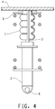
- An example of an installation is shown schematically in Figure 4 .
- the jounce bumper (1) is installed over the shock absorber rod (2), such that displacement of the shock absorber (3) in the upward direction results in axial compression of the jounce bumper between the shock absorber (3) and the chassis (4).
- the jounce bumper (1) can be held in position by a suspension support (5).
- the numeral (6) identifies the end of the shock absorber connected to the wheel axle.
- Jounce bumpers according to the invention were prepared by blow molding copolyetherester elastomer made from an ester of terephthalic acid, e.g. dimethylterephthalate, 1-4 butanediol and a poly(tetramethylene ether) glycol.
- Jounce bumpers E1 and E2 both have Tmax substantially in the middle of the troughs, as so Tmax is designated Tc.
- the weight percentage of short-chain ester units was about 50 and the remainder of the ester units were long-chain ester units.
- the copolyetherester elastomer had a melt flow rate of about 4g/10 minutes at 230°C under 5kg load according to ISO1133. Its hardness was about 47 shore D at 1s according to ISO868.
- a comparative jounce bumper C1 was also prepared from this material.
- the dimensions of the jounce bumpers are listed in Table 2.
- Tc is the maximum wall thickness at a trough (and is alternatively designated Tmax);
- Tm is the wall thickness at the point of tangency between a circle of radius rc and a circle of radius rs, or in cases in which rs and rc are not tangent, Tm is the wall thickness at the midpoint of a line drawn tangent to circles rs and rc; SQRT is square root; P is the pitch; and Ri is the external radius at a trough.
- Compression response was measured using two isolated bellows. The molded parts were cut in this fashion to avoid artifacts from the ends of the jounce bumper.
- the zero mm reference point was an external point located on the plate of the compression machine.
- the molded parts were conditioned by applying 3 compression cycles from 0 to 10KN at 50mm/min at 23°C. The parts were then released and maintained for one hour at a temperature of 23°C without stress. The molded parts were then exposed to a fourth compression cycle using the same conditions as the first three cycles. This last cycle defined the static compression curve of the jounce bumpers.
- Table 2 lists force required to give 50% relative deformation (F50), force required to give 60% relative deformation (F60) and relative deformation at the application of 10KN force (X10KN). It is clear that the force required to cause 50% relative deformation of the jounce bumpers according to the invention, i.e. E1 and E2, which have Tc/Tm of 1.62 and 2.03, respectively, is substantially higher (603 N and 775 N, respectively) than the force required to cause 50% relative deformation in the comparative jounce bumper C1, which has Tc/Tm of 1.15 (529 N). This is also true at 60% relative deformation.
- Jounce bumpers E1 and E2 require forces of 1117 N and 1362 N to cause a deformation of 60%, whereas comparative jounce bumper C1 requires only a force of 793 N to cause the equivalent deformation.
- the relative deflection at 10KN, X10KN is still very high, in fact above 75%, and similar to that exhibited by the comparative jounce bumper C1. This indicates that jounce bumpers according to the invention, E1 and E2, are significantly more effective with respect to absorbing energy than the comparative jounce bumper C1.
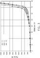
- Results for the comparative jounce bumper C1 and inventive jounce bumpers E1 and E2 are shown graphically in Figure 3 , in which percent deflection (%) is plotted on the X-axis and applied force (N) is plotted on the Y-axis.
- the percent deformation is defined as the ratio of actual deformation in mm to the initial height in mm of the jounce bumper prior to its first compression.
- the results for jounce bumper E1 are shown by the curve designated with triangles.
- the results for jounce bumper E2 are shown by the curve designated with circles.
- the results for comparative jounce bumper C1 are shown by the curve designated by diamonds.
- the area under the curve (Force X % Deflection) gives a measure of the total energy absorbed.
- the compression curve for comparative jounce bumper C1 (diamonds) is the lowest curve.
- Jounce bumpers according to the invention E1 (triangles) and E2 (circles) give higher curves, with greater area under the curve, showing increased absorption of energy.
- jounce bumpers according to the invention E1 and E2 do not significantly sacrifice maximum displacement.
- X10KN for E1 and E2 is not significantly less than X10KN for C1.
Description
- The present invention relates to the field of vehicle suspension systems, and more particularly to jounce bumpers.
- A jounce bumper (also called a bump stop, rebound bumper, end-of-travel bumper, strike-out bumper, suspension bumper, or compression bumper) is a shock-absorbing device ordinarily positioned on the top of vehicle suspensions. Jounce bumpers for use in motor vehicle suspension systems have long been used for cushioning the impact between two suspension system components, such as the axle and a portion of the frame, as well as for attenuating noise and vibration to increase the ride comfort of the passengers. Since displacement of the vehicle chassis causes displacements of the strut, the strut undergoes cycles of compression and extension in response to the displacement of the vehicle chassis. Provision must be made for protecting the strut assembly and the vehicle body from the jounce forces associated with severe irregularities in the road surface leading to extreme displacement of the suspension. For this reason, a jounce bumper is attached to the suspension system at a point where impact is likely to occur when the shock absorber fails to absorb the forces created by extraordinary driving conditions. Particularly, during jounce motions of the strut, the damper "bottoms out" and the jounce bumper moves into contact with the jounce bumper plate and compresses to dissipate energy resulting in cushioning the impact, reducing noise, reducing the sensation of impact to the passengers and reducing possible damage to the vehicle suspension system. Jounce bumpers are elongated, generally cylindrical or conical, members with or without convolutes, made of a compressible and elastomeric material that extends around the piston rod. As taught in
U.S. Patent No. 4,681,304 , convoluted bumpers function by a progressive stacking of the convolutions to provide resistance to jounce forces. - Materials suitable for this application must be resilient, i.e. capable of withstanding shock without undue permanent deformation or rupture, and must have excellent flex life. Conventional jounce bumpers are formed of foamed polyurethane and vulcanized rubber. For example, jounce bumpers are often formed of microcellular polyurethane (MCU). A microcellular polyurethane jounce bumper is made by casting polyurethane precursors in a jounce bumper mold. Microcellular foam is obtained from the reaction of diisocyanate glycol with a blowing agent or with water which produces carbon dioxide gas for foaming. This technology is time-consuming since foaming requires prolonged times in the mold due to the slow release of carbon dioxide. While jounce bumpers made of foamed polyurethane have good ride characteristics, they are expensive to produce since they require an energy- and time-consuming technology due to the crosslinking.
- With the aim of improving durability, inertness to automotive fluids, and resistance to tear propagation of the material used to form the jounce bumper,
U.S. Patent No. 5,192,057 discloses an elongated hollow body formed of an elastomer, preferably from a copolyetherester polymer. As disclosed therein, such pieces, including jounce bumpers having bellows shaped sections with a constant thickness profile, are manufactured by blow molding techniques. An alternative method for forming jounce bumpers, i.e. corrugated extrusion, is described inU.S. Published Patent Application No. 2008/0272529 . - In a typical blow molding operation for manufacturing hollow plastic articles a parison of plastic material that has been produced by extrusion or injection molding and which is in a hot moldable condition is positioned between two halves of an open blow mold having a mold cavity of a shape appropriate to the required external shape of the article to be manufactured. The parison gradually moves and stretches under the influence of gravity. When the parison reaches the proper length, the mold halves are closed around it and pressurized air or other compressed gas is introduced in the interior of the parison to inflate it to the shape of mold or to expand it against the sides of the mold cavity. After a cooling period, the mold is opened and the final article is ejected.
- In extrusion blow molding, the parison is produced by extruders. Extrusion blow molding is less expensive than foaming/casting but leads to less precise dimensions and leads also to limitations in the wall thickness of the part. The stiffness of a jounce bumper is directly related to its thickness.
- Thus, a small variation of thickness (either variation from article to article, along the longitudinal axis of a jounce bumper made from one shot, or along the radius of the convolute of a jounce bumper made in a single jounce bumper), for example 0.2 mm, will significantly change the stiffness of the jounce bumper and its energy absorption capacity and dampening performance.
- Injection blow molding gives more precise dimensions than extrusion blow molding. In this technique, the parison is formed by injection molding, the inner core of the mold is removed and the parison is quickly inflated while being enclosed in two mold halves as in extrusion blow molding. The parison can be injection molded to have a non-constant cross-section resulting in a better wall thickness uniformity of the final part than from extrusion blow molding. Injection blow molding allows more precise details in the final blown structure but is more expensive than extrusion blow molding.
- In general, it is desired to maximize the absorption of energy in a jounce bumper. The energy absorption behavior of a jounce bumper can be measured, for example, by measuring deformation versus applied force. Usually deformation is plotted on the X-axis (in mm), and applied load (force) is plotted on the Y-axis (in N). The area under the curve represents the energy absorbed by the jounce bumper according to the formula displacement X Force = energy.
- Thermoplastic jounce bumpers made by any of the above-mentioned techniques can exhibit different responses depending on design, including specific configuration details, and materials of manufacture. There remains a need to improve the design of thermoplastic jounce bumpers so as to improve the force-displacement behavior, thereby increasing the energy absorbed.
- In a first aspect, the invention provides a jounce bumper made of copolyetherester, comprising:
- a hollow elongated tubular body having a wall, the tubular body having at least two bellows, each bellow being defined by a peak and a trough, the peak having a fillet radius of rs, the trough having a fillet radius of rc and a maximum wall thickness of the trough being at a point within the trough and designated Tmax; wherein rc is greater than rs, and wherein the ratio of
Tmax, the maximum thickness of the wall in a trough, to Tm, the thickness of the wall at an intermediate point between peak and trough, is greater than or equal to 1.2, and wherein the trough is defined by a wall arc having end points at the intermediate points where the wall thickness is Tm. - In a second aspect, the invention provides a jounce bumper made of copolyetherester, comprising:
- a hollow elongated tubular body having a wall, the tubular body having at least two bellows, each bellow being defined by a peak and a trough, the peak having a fillet radius of rs, the trough having a fillet radius of rc and a wall thickness at the trough of Tc (Tc being Tmax in the case when Tmax falls substantially in the middle of the trough); wherein rc is greater than rs, and wherein the ratio of Tc (Tmax), the thickness of the wall at a trough, to Tm, the thickness of the wall at an intermediate point between peak and trough, is greater than or equal to 1.2.
- In a third aspect, the invention provides a method for the manufacture of a jounce bumper, comprising the step of:
- shaping copolyetherester material into a hollow elongated tubular body having a wall, the tubular body having at least two bellows, each bellow being defined by a peak and a trough, the peak having a fillet radius of rs, the trough having a fillet radius of rc and a maximum wall thickness of the trough being at a point within the trough and designated Tmax;
- wherein rc is greater than rs, and wherein the ratio of Tmax, the maximum thickness of the wall in a trough, to Tm, the thickness of the wall at an intermediate point between peak and trough, is greater than or equal to 1.2, and wherein the trough is defined by the wall arc having end points at the intermediate points where the wall thickness is Tm.
- In a fourth aspect, the invention provides a method for the manufacture of a jounce bumper, comprising the step of:
- shaping copolyetherester material into a hollow elongated tubular body having a wall, the tubular body having at least two bellows, each bellow being defined by a peak and a trough, the peak having a fillet radius of rs, the trough having a fillet radius of rc and a wall thickness at the trough of Tc (Tc being Tmax in the case when Tmax falls substantially in the middle of the trough); wherein rc is greater than rs, and wherein the ratio of Tc (Tmax), the
thickness of the wall at a trough, to Tm, the thickness of the wall at an intermediate point between peak and trough, is greater than or equal to 1.2. - In a fifth aspect, the invention provides a method for absorbing shocks in an automobile suspension comprising using a jounce bumper to absorb energy from displacement of the suspension, wherein the jounce bumper is made of copolyetherester and comprises a hollow elongated tubular body having a wall, the tubular body having at least two bellows, each bellow being defined by a peak and a trough, the peak having a fillet radius of rs, the trough having a fillet radius of rc and a maximum wall thickness of the trough being at a point within the trough and designated Tmax; wherein rc is greater than rs, and wherein the ratio of Tmax, the maximum thickness of the wall in a trough, to Tm, the thickness of the wall at an intermediate point between peak and trough, is greater than or equal to 1.2, and wherein the trough is defined by the wall arc having end points at the intermediate points where the wall thickness is Tm.
- In a sixth aspect, the invention provides a method for absorbing shocks in an automobile suspension comprising using a jounce bumper to absorb energy from displacement of the suspension, wherein the jounce bumper is made of copolyetherester and comprises a hollow elongated tubular body having a wall, the tubular body having at least two bellows, each bellow being defined by a peak and a trough, the peak having a fillet radius of rs, the trough having a fillet radius of rc and a wall thickness at the trough of Tc (Tc being Tmax in the case when Tmax falls substantially in the middle of the trough); wherein rc is greater than rs, and wherein the ratio of Tc (Tmax), the thickness of the wall at a trough, to Tm, the thickness of the wall at an intermediate point between peak and trough, is greater than or equal to 1.2.
-
-
Figure 1 is a schematic broken view of an "inward" jounce bumper, wherein Re designates the external radius at a peak, Ri designates the external radius at a trough, and P represents the distance from peak to peak (the pitch). -
Figure 2A is a schematic cross-section enlarged view ofFigure 1 , wherein the dashed line represents the longitudinal axis of the jounce bumper, rs designates the fillet radius of an outward convolute, and rc designates the fillet radius on an inward convolute, Ts designates the wall thickness at the
peak of an outward convolute, Tc (also Tmax) designates the wall thickness at the trough (inward convolute) in the case where the maximum wall thickness Tmax occurs at the middle of the trough, and Tm designates the intermediate wall thickness at the point of tangency between a circle having radius rc and a circle having radius rs. The trough is defined by the wall arc having end points of Tm. -
Figure 2B is a schematic cross-section enlarged view of a jounce bumper showing the case when circles of radius rs and rc are not tangent. The dashed line represents the longitudinal axis of the jounce bumper, rs designates the fillet radius of an outward convolute, and rc designates the fillet radius on an inward convolute, Ts designates the wall thickness at the peak of an outward convolute, Tc (Tmax) designates the wall thickness at the trough (inward convolute) in the case where the maximum wall thickness Tmax occurs at the middle of the trough, and Tm designates the intermediate wall thickness at the mid-point of a line drawn tangent to both a circle having radius rc and a circle having radius rs. -
Figure 3 illustrates percent deformation (deflection) (%) on the X-axis vs. applied force (N) on the Y-axis for jounce bumpers according to the invention, i.e. E1 and E2, and a comparative jounce bumper, i.e. C1. The percent deformation is defined as the ratio of actual deformation in mm to the initial height in mm of the jounce bumper (after 2-4 preconditioning compressions). The curve for E1 is designated with triangles, the curve for E2 is designated with circles and the curve for C1 is designated with diamonds. -
Figure 4 shows a partially cut-away view of one example of a jounce bumper as installed in the suspension of an automobile. - The inventors have found that in a jounce bumper made from copolyetherester, when the ratio of (Tmax/Tm) of the maximum wall thickness in a trough (Tmax) to the thickness of the wall at an intermediate point between peak and trough Tm is greater than or equal to 1.2, superior absorption of energy is obtained, as measured, for example, by deformation versus applied force. In a preferred embodiment, the maximum wall thickness in the trough occurs substantially in the middle of the trough, in which case Tmax is designated Tc.
- The inventors have found that in a jounce bumper made from copolyetherester, when the ratio (Tc/Tm) of thickness of the wall at a trough (Tc) to the thickness of the wall at an intermediate point between peak and trough (Tm) is greater than or equal to 1.2, superior absorption of energy is obtained, as measured, for example, by deformation versus applied force. As used herein the term superior energy absorption means both a high force along the displacement, i.e. at least 550N for 50% relative deformation and at the same time a high level of deformation when the force is very high, i.e. at least 65% relative deformation at 10KN. The level of energy absorption can be estimated by the force level at 50 and/or 60% relative deformation and the relative deformation at 10KN.
- Tc (Tmax) and Tm are often measured for all convolutes in a jounce bumper and the average values are taken as Tc (Tmax) and Tm, due to small variations from convolute to convolute.
- The invention relates to "inward" jounce bumpers, which are those in which the peak fillet radius, rs, is smaller than the trough fillet radius, rc (i.e. rc > rs), as exemplified in
Figures 2A and 2B . - The principle of the invention can be better understood by examining
Figures 1 ,2A and2B .Figure 1 shows a typical "inward" jounce bumper. It is a hollow tube-shaped article, having outward and inward convolutes. The geometry will be defined by a pitch (P) which is the distance from one peak to the next, the external radius at a peak (Re), and the external radius at a trough (Ri). Both Re and Ri are measured from the longitudinal axis of the jounce bumper (i.e. the imaginary line that passes longitudinally through the centre of the jounce bumper). The outermost point on an outward convolute is referred to as a peak, and the point of most inward pinching (without taking into account the thickness of the convolutes) is referred to as a trough. -
Figure 2A shows an enlargement of a bellows consisting of an outward convolute and an inward convolute. The outward convolute (top) is defined by a radius rs, and the inward convolute (bottom) is defined by a radius rc. An "inward" jounce bumper is any jounce bumper in which rc is greater than rs. If circles are drawn having radii rs and rc, the point of tangency of these two circles is a point on the wall of the jounce bumper intermediate between a peak and a trough. The wall of the jounce bumper at this point has thickness Tm. As shown inFigure 2B , in cases in which there is no point of tangency between circles rs and rc, Tm is defined as the middle of the segment of the tangent to rs and rc circles. A trough is defined by the wall arc having end points of Tm. The maximum wall thickness in the trough is designated Tmax. In cases where Tmax occurs substantially in the middle of the trough, Tmax is designated Tc. The inventors have found that when the ratio (Tmax/Tm) of maximum thickness of the wall in a trough (Tmax) to the thickness of the wall at an intermediate point between peak and trough (Tm) is greater than or equal to 1.2, a jounce bumper showing superior absorption of energy is obtained. - In preferred embodiments, Tmax/Tm is greater than 1.3, more preferably greater than 1.5, for example 1.62 or 2.03. The upper value of Tmax/Tm is not particularly limited, although in practice it is rare for Tmax/Tm to be greater than 10.
- In all cases in which Tmax occurs substantially in the middle of a trough, Tmax can be designated Tc.
- Jounce bumpers according to the invention maximize the energy absorbed, as measured by displacement (or deformation) versus applied force. In a preferred embodiment, the jounce bumpers also maximize the displacement achieved for a given applied force, and maximize the displacement at maximum force (i.e. when the jounce bumper is fully compressed). The displacement at maximum force (full compression) is often measured at a force of ten kiloNewtons (10 kN) and is referred to as X10KN, for a relative deformation X at an applied force of ten kiloNewtons. To maximize energy absorption and maximize X10KN, the inventors have found that it is desirable not only that Tmax/Tm be greater than or equal to 1.2, but also that the ratio of the maximum wall thickness in a trough, Tmax, to the wall thickness at the intermediate point, Tm, be greater than a certain value, which certain value is dependant on the pitch, P, maximum wall thickness at a trough, Tmax, and the external radius at a trough, Ri. This can be expressed by the following combination of features:


- Tmax is the maximum wall thickness at a trough;
- Tm is the wall thickness at the point of tangency between a circle of radius rc and a circle of radius rs, or in cases in which rs and rc are not tangent, Tm is the wall thickness at the midpoint of a line drawn tangent to circles rs and rc; SQRT is square root;
- P is the pitch; and
- Ri is the external radius at a trough.
- Tc is the maximum wall thickness at a trough;
- Tm is the wall thickness at the point of tangency between a circle of radius rc and a circle of radius rs, or in cases in which rs and rc are not tangent, Tm is the wall thickness at the midpoint of a line drawn tangent to circles rs and rc; SQRT is square root;
- P is the pitch; and
- Ri is the external radius at a trough.
- For use with automobiles, a typical pitch, P, is between at or about 10 and 30 mm, more preferably between at or about 13 and 23 mm, the thicknesses Tc and Tm are typically chosen between at or about 2 and 5 mm, more preferably between at or about 2 and 4 mm, and Ri is typically at or about 10 to 40 mm, more preferably at or about 15 to 25 mm.
- The number of convolutes and the overall height of the jounce bumper can be chosen depending on the size and weight of the vehicle.
- The jounce bumper of the invention is made of copolyetherester. Preferably, a copolyetherester is used that has a relatively high melt viscosity (i.e. a melt flow rate between 0.5 and 8 g/10min, more preferably between 1 and 8 g/10 min, more preferably between 2 and 6 g/10 min, more preferably between 3 and 5 g/10 min, particularly preferably 4 g/10 min at 230°C under 5kg load according to ISO1133). Preferably the copolyetherester has a hardness between at or about 45 and 60D, more preferably at or about 47 to 55D (at 1s according to ISO868). Particularly preferably the copolyetherester is a segmented copolyetherester having soft segments of polytetramethylene ether glycol (PTMEG).
- Examples of copolyetheresters useful for the jounce bumper of the present invention include those defined in ISO 18064:2003(E).
- Thermoplastic polyolefinic elastomers (TPO's) consist of thermoplastic olefinic polymers, for example polypropylene or polyethylene, blended with a thermoset elastomer. A typical TPO is a melt blend or reactor blend of a polyolefin plastic, generally a polypropylene polymer, with an olefin copolymer elastomer, typically an ethylene-propylene rubber (EPR) or an ethylenepropylene-diene rubber (EPDM). Common olefin copolymer elastomers include EPR, EPDM, and ethylene copolymers such as ethylene-butene, ethylene-hexene, and ethylene-octene copolymer elastomers (for example Engage® polyolefin elastomer, which is commercially available from The Dow Chemical Co.) and ethylene-butadiene rubber.
- Styrenic thermoplastic elastomers (TPS's) consist of block copolymers of polystyrene and rubbery polymeric materials, for example polybutadiene, a mixture of hydrogenated polybutadiene and polybutadiene, poly(ethylene-propylene) and hydrogenated polyisoprene. Specific block copolymers of the styrene/conjugated diene/styrene type are SBS, SIS, SIBS, SEBS and SEPS block copolymers. These block copolymers are known in the art and are commercially available.
- Thermoplastic polyurethanes (TPU's) consist of linear segmented block copolymers composed of hard segments comprising a diisocyanate, a short chain glycol and soft segments comprising diisocyanate and a long chain polyol as represented by the general formula

"X" represents a hard segment comprising a diisocyanate and a short-chain glycol, "Z" represents a soft segment comprising a diisocyanate and a long-chain polyol and "Y" represents the residual group of the diisocyanate compound of the urethane bond linking the X and Z segments. The long-chain polyol includes those of a polyether type such as poly(alkylene oxide)glycol or those of polyester type. - Thermoplastic vulcanizates (TPV's) consist of a continuous thermoplastic phase with a phase of vulcanized elastomer dispersed therein. Vulcanizate and the phrase "vulcanizate rubber" as used herein are intended to be generic to the cured or partially cured, crosslinked or crosslinkable rubber as well as curable precursors of crosslinked rubber and as such include elastomers, gum rubbers and so-called soft vulcanizates. TPV's combine many desirable characteristics of crosslinked rubbers with some characteristics, such as processability, of thermoplastic elastomers. There are several commercially available TPVs, for example Santoprene® and Sarlink® (TPV's based on ethylene-propylene-diene copolymers and polypropylene) which are respectively commercially available from Advanced Elastomer Systems and DSM; Nextrile™ (TPV based on nitrile rubber and polypropylene) which is commercially available from Thermoplastic Rubber Systems; Zeotherm® (TPV based on acrylate elastomer and polyamide) which is commercially available from Zeon Chemicals; and DuPont™ ETPV from E. I. du Pont de Nemours and Company, which is described in International Patent Application Publication
WO 2004/029155 (thermoplastic blends comprising from 15 to 60 wt. % of polyalkylene phthalate polyester polymer or copolymer and from 40 to 85 wt. % of a crosslinkable poly(meth)acrylate or polyethylene/(meth)acrylate rubber dispersed phase, wherein the rubber has been dynamically crosslinked with a peroxide free radical initiator and an organic diene co-agent). - Thermoplastic polyamide block copolymers (TPA's) consist of linear and regular chains of polyamide segments and flexible polyether or polyester segments or soft segments with both ether and ester linkages as represented by the general formula

"PA" represents a linear saturated aliphatic polyamide sequence and "PE" represents for example a polyoxyalkylene sequence formed from linear or branched aliphatic polyoxyalkylene glycols or a long-chain polyol with either ether linkages, ester linkages or linkages of both types and mixtures thereof or copolyethers and copolyesters derived therefrom. The softness of the copolyetheramide or the copolyesteramide block copolymers generally decreases as the relative amount of polyamide units is increased. - Examples of thermoplastic polyamide block copolymers are commercially available from Arkema or Elf Atochem under the trademark Pebax®.
- For an excellent balance of grease resistance, high temperature durability and low temperature flexibility, the jounce bumper according to the present invention is made from copolyetherester compositions. Thermoplastic polyesters are typically derived from one or more dicarboxylic acids (where herein the term "dicarboxylic acid" also refers to dicarboxylic acid derivatives such as esters) and one or more diols. In polyesters the dicarboxylic acids may comprise one or more of terephthalic acid, isophthalic acid, and 2,6-naphthalene dicarboxylic acid, and the diol component comprises one or more of HO(CH2)nOH (I); 1,4-cyclohexanedimethanol; HO(CH2CH2O)mCH2CH2OH (II); and HO(CH2CH2CHZCH2O)zCH2CH2CH2CH2OH (III), wherein n is an integer of 2 to 10, m on average is 1 to 4, and z is on average about 7 to about 40. Note that (II) and (III) may be a mixture of compounds in which m and z, respectively, may vary and that since m and z are averages, they need not be integers. Other dicarboxylic acids that may be used to form the thermoplastic polyester include sebacic and adipic acids. Hydroxycarboxylic acids such as hydroxybenzoic acid may be used as comonomers. Specific polyesters include poly(ethylene terephthalate) (PET), poly(trimethylene terephthalate) (PTT), poly(1,4-butylene terephthalate) (PBT), poly(
ethylene 2,6-naphthoate), and poly(1,4-cyclohexyldimethylene terephthalate) (PCT). - Copolyester thermoplastic elastomers (TPC) such as copolyetheresters or copolyesteresters are copolymers that have a multiplicity of recurring long-chain ester units and short-chain ester units joined head-to-tail through ester linkages, said long-chain ester units being represented by formula (A):


G is a divalent radical remaining after the removal of terminal hydroxyl groups from poly(alkylene oxide)glycols having preferably a number average molecular weight of between about 400 and about 6000; R is a divalent radical remaining after removal of carboxyl groups from a dicarboxylic acid having a molecular weight of less than about 300; and D is a divalent radical remaining after removal of hydroxyl groups from a diol having a molecular weight preferably less than about 250; and wherein said copolyetherester(s) preferably contain from about 15 to about 99 wt. % short-chain ester units and about 1 to about 85 wt. % long-chain ester units. - As used herein, the term "long-chain ester units" as applied to units in a polymer chain refers to the reaction product of a long-chain glycol with a dicarboxylic acid. Suitable long-chain glycols are poly(alkylene oxide) glycols having terminal (or as nearly terminal as possible) hydroxy groups and having a number average molecular weight of from about 400 to about 6000, and preferably from about 600 to about 3000. Preferred poly(alkylene oxide) glycols include poly(tetramethylene oxide) glycol, poly(trimethylene oxide) glycol, poly(propylene oxide) glycol, poly(ethylene oxide) glycol, copolymer glycols of these alkylene oxides, and block copolymers such as ethylene oxide-capped poly(propylene oxide) glycol. Mixtures of two or more of these glycols can be used.
- The term "short-chain ester units" as applied to units in a polymer chain of the copolyetheresters refers to low molecular weight compounds or polymer chain units. They are made by reacting a low molecular weight diol or a mixture of diols with a dicarboxylic acid to form ester units represented by Formula (B) above. Included among the low molecular weight diols which react to form short-chain ester units suitable for use for preparing copolyetheresters are acyclic, alicyclic and aromatic dihydroxy compounds. Preferred compounds are diols with about 2-15 carbon atoms such as ethylene, propylene, isobutylene, tetramethylene, 1,4-pentamethylene, 2,2dimethyltrimethylene, hexamethylene and decamethylene glycols, dihydroxycyclohexane, cyclohexane dimethanol, resorcinol, hydroquinone, 1,5-dihydroxynaphthalene, and the like. Especially preferred diols are aliphatic diols containing 2-8 carbon atoms, and a more preferred diol is 1,4butanediol.
- Copolyetheresters that have been advantageously used for the manufacture of the jounce bumper of the present invention are commercially available from E. I. du Pont de Nemours and Company, Wilmington, Delaware under the trademark Hytrel® copolyetherester elastomer.
- Jounce bumpers according to the present invention are made of copolyetheresters. More preferably a copolyetherester is used that is made from an ester of terephthalic acid, e.g. dimethylterephthalate, 1-4 butanediol and a poly(tetramethylene ether) glycol. The weight percent of short-chain ester units is about 50 where the remainder is long-chain ester units. The copolyetherester elastomer has a high melt viscosity with a melt flow rate of about 4g/10mn at 230°C under 5kg load as measured according to ISO1133. Its hardness is about 47 shore D at 1s as measured according to ISO868.
- The material used to manufacture the jounce bumpers according to the present invention may comprise additives including plasticizers; stabilizers; antioxidants; ultraviolet absorbers; hydrolytic stabilizers; anti-static agents; dyes or pigments; fillers, fire retardants; lubricants; reinforcing agents such as fibers, flakes or particles of glass; minerals, ceramics, carbon among others, including nano-scale particles; processing aids, for example release agents; and/or mixtures thereof. Suitable levels of these additives and methods of incorporating these additives into polymer compositions are known to those of skill in the art.
- The jounce bumper of the invention may be made by any shaping operation or method suitable for shaping copolyetherester material. Examples of such shaping operations or methods comprise operations that include: injection molding, extrusion (e.g. corrugated extrusion), and blow molding (including extrusion blow molding and injection blow molding). Blow molding is particularly preferred as it allows good control over the final geometry of the part and a good balance between the control of the final geometry and the cost of the process.
- Some dimensions of two examples of jounce bumpers according to the invention are listed in Table 1 below. Table 1 concerns two jounce bumpers in which Tmax occurs substantially at the middle of the trough, and so Tmax is designated Tc:
TABLE 1 Dimensions of Two Examples of Jounce Bumpers According to the Invention Unit Example A Example B Tc (= Tmax, average for all troughs) mm 2.83 3.05 Tm (average for all convolutes) mm 1.75 1.5 Ratio Tc/Tm -- 1.62 2.03 Pitch (P) mm 15 15 Ri (external radius at trough) mm 21.6 21.6 - In use, the jounce bumper is installed on a suspension rod of a vehicle between the vehicle chassis and a shock absorber. An example of an installation is shown schematically in
Figure 4 . Referring toFigure 4 , the jounce bumper (1) is installed over the shock absorber rod (2), such that displacement of the shock absorber (3) in the upward direction results in axial compression of the jounce bumper between the shock absorber (3) and the chassis (4). If desired, the jounce bumper (1) can be held in position by a suspension support (5). The numeral (6) identifies the end of the shock absorber connected to the wheel axle. - Jounce bumpers according to the invention, E1 and E2, were prepared by blow molding copolyetherester elastomer made from an ester of terephthalic acid, e.g. dimethylterephthalate, 1-4 butanediol and a poly(tetramethylene ether) glycol. Jounce bumpers E1 and E2 both have Tmax substantially in the middle of the troughs, as so Tmax is designated Tc. The weight percentage of short-chain ester units was about 50 and the remainder of the ester units were long-chain ester units. The copolyetherester elastomer had a melt flow rate of about 4g/10 minutes at 230°C under 5kg load according to ISO1133. Its hardness was about 47 shore D at 1s according to ISO868. A comparative jounce bumper C1 was also prepared from this material.
- The dimensions of the jounce bumpers are listed in Table 2. The jounce bumpers according to the invention, E1 and E2, had Tc/Tm > 1.2 (alternatively expressed as Tmax/Tm > 1.2), whereas the jounce bumper of comparative example C1, had Tc/Tm = 1.15 (i.e. less than 1.2).
- Additionally, jounce bumpers E1 and E2 meet the requirements:


Tc is the maximum wall thickness at a trough (and is alternatively designated Tmax);
Tm is the wall thickness at the point of tangency between a circle of radius rc and a circle of radius rs, or in cases in which rs and rc are not tangent, Tm is the wall thickness at the midpoint of a line drawn tangent to circles rs and rc; SQRT is square root;
P is the pitch; and
Ri is the external radius at a trough.TABLE 2 Dimensions and Compression Behavior of Jounce Bumpers Unit C1 E1 E2 Original height mm 29.1 29.4 29.8 Tc(average for all troughs) mm 2.42 2.83 3.05 Tm (average for all convolutes) mm 2.1 1.75 1.5 Average thickness Ts mm 2.4 1.80 1.5 Ratio Tc/Tm -- 1.15 1.62 2.03 Pitch (P) mm 15 15 15 Ri (external radius at trough) mm 21.6 21.6 21.6 Force at 50% rel. def. F50 N 529 603 775 Force at 60% rel. def. F60 N 793 1117 1362 Rel. Def. at 10KN, X10KN % 77.5 76.9 75.1 - Results of calculations [i.e. calculated values of (Tc/Tm)1 as compared to Tc/Tm] are shown in Table 3.
- For jounce bumpers E1 and E2, Tc/Tm > (Tc/Tm)1, whereas for comparative jounce bumper C1, Tc/Tm < (Tc/Tm)1.
TABLE 3 Tc/Tm of Jounce Bumpers Jounce bumper Tc/Tm (Tc/Tm)1 (calculated) C1 (comparative) 1.15 1.32 E1 1.62 1.32 E2 2.03 1.32 - Compression response was measured using two isolated bellows. The molded parts were cut in this fashion to avoid artifacts from the ends of the jounce bumper. The zero mm reference point was an external point located on the plate of the compression machine.
- The molded parts were conditioned by applying 3 compression cycles from 0 to 10KN at 50mm/min at 23°C. The parts were then released and maintained for one hour at a temperature of 23°C without stress. The molded parts were then exposed to a fourth compression cycle using the same conditions as the first three cycles. This last cycle defined the static compression curve of the jounce bumpers.
- Table 2 lists force required to give 50% relative deformation (F50), force required to give 60% relative deformation (F60) and relative deformation at the application of 10KN force (X10KN). It is clear that the force required to cause 50% relative deformation of the jounce bumpers according to the invention, i.e. E1 and E2, which have Tc/Tm of 1.62 and 2.03, respectively, is substantially higher (603 N and 775 N, respectively) than the force required to cause 50% relative deformation in the comparative jounce bumper C1, which has Tc/Tm of 1.15 (529 N). This is also true at 60% relative deformation. Jounce bumpers E1 and E2 require forces of 1117 N and 1362 N to cause a deformation of 60%, whereas comparative jounce bumper C1 requires only a force of 793 N to cause the equivalent deformation. The relative deflection at 10KN, X10KN, is still very high, in fact above 75%, and similar to that exhibited by the comparative jounce bumper C1. This indicates that jounce bumpers according to the invention, E1 and E2, are significantly more effective with respect to absorbing energy than the comparative jounce bumper C1.
- Results for the comparative jounce bumper C1 and inventive jounce bumpers E1 and E2 are shown graphically in
Figure 3 , in which percent deflection (%) is plotted on the X-axis and applied force (N) is plotted on the Y-axis. The percent deformation is defined as the ratio of actual deformation in mm to the initial height in mm of the jounce bumper prior to its first compression. The results for jounce bumper E1 are shown by the curve designated with triangles. The results for jounce bumper E2 are shown by the curve designated with circles. The results for comparative jounce bumper C1 are shown by the curve designated by diamonds. - The area under the curve (Force X % Deflection) gives a measure of the total energy absorbed. The compression curve for comparative jounce bumper C1 (diamonds) is the lowest curve. Jounce bumpers according to the invention E1 (triangles) and E2 (circles) give higher curves, with greater area under the curve, showing increased absorption of energy.
- Additionally, it can be seen from
Figure 3 that jounce bumpers according to the invention E1 and E2 do not significantly sacrifice maximum displacement. X10KN for E1 and E2 is not significantly less than X10KN for C1.

Claims (15)
- A jounce bumper made of copolyetherester, comprising:a hollow elongated tubular body having a wall, the tubular body having at least two bellows, each bellow being defined by a peak and a trough, the peak having a fillet radius of rs, the trough having a fillet radius of rc and a maximum wall thickness in the trough of Tmax; wherein rc is greater than rs, characterized in that the ratio of Tmax, the maximum thickness of the wall in a trough to Tm, the thickness of the wall at an intermediate point between the peak and the trough, is greater than or equal to 1.2, and wherein the trough is defined by a wall arc having end points at the intermediate points where the wall thickness is Tm.
- A jounce bumper according to claim 1, wherein (Tmax/Tm), the ratio of maximum wall thickness in the trough to the thickness of the wall at an intermediate point, is greater than (Tmax/Tm)1,
wherein Tmax is the maximum wall thickness at a trough;Tm is the wall thickness at the intermediate point wherein the intermediate point is the point of tangency between a circle of radius rc and a circle of radius rs, or if rs and rc are not tangent, Tm is the wall thickness at the intermediate point wherein the intermediate point is the midpoint of a line drawn tangent to circles rs and rc;SQRT is square root;P is the pitch; andRi is the external radius at a trough.
 - A jounce bumper according to claim 1 wherein the copolyetherester has a melt viscosity between 0.5 and 8 g/10minutes, at 230°C under 5kg load measured according to ISO1133, and a hardness between at or about 45 and 60D measured at 1s according to ISO868.
- A jounce bumper according to claim 2 wherein the copolyetherester has a melt viscosity between 0.5 and 8 g/10minutes, at 230°C under 5kg load measured according to ISO1133, and a hardness between at or about 45 and 60D measured at 1s according to ISO868.
- A jounce bumper according to claim 1 wherein the copolyetherester has a melt viscosity between 2 and 6 g/10minutes, at 230°C under 5kg load measured according to ISO1133, and a hardness between at or about 45 and 60D measured at 1s according to ISO868.
- A jounce bumper according to claim 2 wherein the copolyetherester has a melt viscosity between 2 and 6 g/10minutes, at 230°C under 5kg load measured according to ISO1133, and a hardness between at or about 45 and 60D measured at 1s according to ISO868.
- A jounce bumper according to claim 1 wherein the copolyetherester has a melt viscosity between 3 and 5 g/10minutes, at 230°C under 5kg load measured according to ISO1133, and a hardness between at or about 45 and 60D measured at 1s according to ISO868.
- A jounce bumper according to claim 2 wherein the copolyetherester has a melt viscosity between 3 and 5 g/10minutes, at 230°C under 5kg load measured according to ISO1133, and a hardness between at or about 45 and 60D measured at 1s according to ISO868.
- A jounce bumper according to claim 1 wherein the copolyetherester are copolymers having a multiplicity of recurring long-chain ester units and short-chain ester units joined head-to-tail through ester linkages, said long-chain ester units being represented by formula (A):


G is a divalent radical remaining after the removal of terminal hydroxyl groups from poly(alkylene oxide)glycols having preferably a number average molecular weight of between about 400 and about 6000; R is a divalent radical remaining after removal of carboxyl groups from a dicarboxylic acid having a molecular weight of less than about 300; and D is a divalent radical remaining after removal of hydroxyl groups from a diol having a molecular weight preferably less than about 250; and wherein said copolyetherester(s) preferably contain from about 15 to about 99 wt-% short-chain ester units and about 1 to about 85 wt-% long-chain ester units. - A method for the manufacture of a jounce bumper, comprising the step of:shaping copolyetherester material into a hollow elongated tubular body having a wall, the tubular body having at least two bellows, each bellow being defined by a peak and a trough, the peak having a fillet radius of rs, the trough having a fillet radius of rc and a maximum wall thickness at the trough of Tmax; wherein rc is greater than rs,characterized in that the ratio of Tmax, the maximum thickness of the wall at a trough, to Tm, the thickness of the wall at an intermediate point between peak and trough, is greater than or equal to 1.2, and wherein the trough is defined by the wall arc having end points at the intermediate points where the wall thickness is Tm.
- A method of claim 10, wherein the method of shaping comprises a shaping operation selected from the group consisting of injection molding, extrusion, and blow molding.
- A method for absorbing shocks in an automobile suspension comprising using a jounce bumper to absorb energy from displacement of the suspension, wherein the jounce bumper is made of copolyetherester and comprises a hollow elongated tubular body having a wall, the tubular body having at least two bellows, each bellow being defined by a peak and a trough, the peak having a fillet radius of rs, the trough having a fillet radius of rc and a maximum wall thickness at the trough of Tmax; wherein rc is greater than rs, characterized in that the ratio of Tmax the thickness of the wall at a trough, to Tm, the thickness of the wall at an intermediate point between peak and trough, is greater than or equal to 1.2.
- A jounce bumper according to claim 1 wherein Tmax occurs substantially in the middle of the trough.
- A method according to claim 10 wherein Tmax occurs substantially in the middle of the trough.
- An automobile suspension comprising the jounce bumper of any of claims 1 through 9 or the jounce bumper of claim 13 installed on the suspension rod of the automobile.
Priority Applications (1)
| Application Number | Priority Date | Filing Date | Title |
|---|---|---|---|
| PL11750006T PL2603714T3 (en) | 2010-08-12 | 2011-08-10 | Thermoplastic jounce bumpers |
Applications Claiming Priority (3)
| Application Number | Priority Date | Filing Date | Title |
|---|---|---|---|
| US37298510P | 2010-08-12 | 2010-08-12 | |
| US201161479458P | 2011-04-27 | 2011-04-27 | |
| PCT/US2011/047242 WO2012021612A1 (en) | 2010-08-12 | 2011-08-10 | Thermoplastic jounce bumpers |
Publications (2)
| Publication Number | Publication Date |
|---|---|
| EP2603714A1 EP2603714A1 (en) | 2013-06-19 |
| EP2603714B1 true EP2603714B1 (en) | 2018-02-14 |
Family
ID=44534669
Family Applications (1)
| Application Number | Title | Priority Date | Filing Date |
|---|---|---|---|
| EP11750006.6A Active EP2603714B1 (en) | 2010-08-12 | 2011-08-10 | Thermoplastic jounce bumpers |
Country Status (10)
| Country | Link |
|---|---|
| US (4) | US8657271B2 (en) |
| EP (1) | EP2603714B1 (en) |
| JP (2) | JP6235339B2 (en) |
| KR (1) | KR101924654B1 (en) |
| CN (1) | CN103080594B (en) |
| BR (1) | BR112013003274B8 (en) |
| ES (1) | ES2666327T3 (en) |
| PL (1) | PL2603714T3 (en) |
| RU (1) | RU2013110523A (en) |
| WO (1) | WO2012021612A1 (en) |
Families Citing this family (24)
| Publication number | Priority date | Publication date | Assignee | Title |
|---|---|---|---|---|
| US8657271B2 (en) | 2010-08-12 | 2014-02-25 | E I Du Pont De Nemours And Company | Thermoplastic jounce bumpers |
| US20120193851A1 (en) * | 2010-08-12 | 2012-08-02 | E.I.Du Pont De Nemours And Company | Thermoplastic jounce bumpers |
| US20130161888A1 (en) * | 2011-12-21 | 2013-06-27 | E I Du Pont De Nemours And Company | Jounce bumper |
| ITTO20120473A1 (en) | 2012-05-31 | 2013-12-01 | Insit Ind S P A | DAMPING BUFFER FOR VEHICLE SUSPENSIONS |
| KR20150068414A (en) | 2012-10-02 | 2015-06-19 | 바스프 에스이 | Damper |
| US9624911B1 (en) | 2012-10-26 | 2017-04-18 | Sunfolding, Llc | Fluidic solar actuator |
| JP6207310B2 (en) * | 2013-09-12 | 2017-10-04 | 住友理工株式会社 | Dust cover |
| US9394962B2 (en) * | 2013-09-12 | 2016-07-19 | Sumitomo Riko Company Limited | Dust cover |
| KR101551061B1 (en) * | 2014-02-17 | 2015-09-07 | 현대자동차주식회사 | Bumper stopper united with dust cover |
| JP5798656B1 (en) * | 2014-03-26 | 2015-10-21 | 住友理工株式会社 | Urethane bumper spring and its manufacturing method |
| US20150344181A1 (en) * | 2014-05-27 | 2015-12-03 | Katrina Goff Candy | Sealable Collapsible Container |
| EP3188918A1 (en) * | 2014-09-01 | 2017-07-12 | Jaguar Land Rover Limited | Spring aid assembly for a vehicle suspension system |
| PE20171505A1 (en) | 2015-01-30 | 2017-10-20 | Sunfolding Inc | FLUID ACTUATOR METHOD AND SYSTEM |
| KR102524967B1 (en) * | 2015-02-18 | 2023-04-21 | 듀폰 폴리머스, 인크. | jounce bumper |
| WO2017172902A1 (en) | 2016-03-29 | 2017-10-05 | Other Lab, Llc | Fluidic robotic actuator system and method |
| US10598251B2 (en) * | 2017-04-14 | 2020-03-24 | The Boeing Company | Vibration damping link and method therefore |
| EP3926819A1 (en) | 2017-04-17 | 2021-12-22 | Sunfolding, Inc. | Pneumatic actuator system and method |
| CN107336575B (en) * | 2017-07-25 | 2018-11-06 | 嘉兴尚云自动化设备有限公司 | A kind of suspension of electric vehicle |
| CN109456577A (en) * | 2017-09-06 | 2019-03-12 | 浙江台州多邦高分子材料科技有限公司 | A kind of macromolecular elastomer spring |
| CN109456576A (en) * | 2017-09-06 | 2019-03-12 | 浙江台州多邦高分子材料科技有限公司 | A kind of macromolecule damping spring |
| AU2019277145B2 (en) | 2018-05-29 | 2023-06-08 | Sunfolding, Inc. | Tubular fluidic actuator system and method |
| JP7328844B2 (en) | 2019-09-18 | 2023-08-17 | Toyo Tire株式会社 | expansion member |
| EP4169157A1 (en) | 2020-06-22 | 2023-04-26 | Sunfolding, Inc. | Locking, dampening and actuation systems and methods for solar trackers |
| DE102022002550A1 (en) * | 2022-07-12 | 2024-01-18 | Günther Zimmer | Spring-damper system with end lag stop and two-wheel vehicle with spring-damper system |
Family Cites Families (19)
| Publication number | Priority date | Publication date | Assignee | Title |
|---|---|---|---|---|
| US3118659A (en) * | 1960-02-09 | 1964-01-21 | Luxembourg Brev Participations | Compression springs made of an elastomer |
| US4235427A (en) | 1979-05-07 | 1980-11-25 | Walter Bialobrzeski | Spring |
| JPS58128062A (en) | 1982-01-23 | 1983-07-30 | Akai Electric Co Ltd | Automatic rejection signal producing system in disc player |
| JPS59166736A (en) | 1983-03-11 | 1984-09-20 | Matsushita Electric Ind Co Ltd | Vibro-isolating device |
| JPS6035938A (en) | 1983-08-03 | 1985-02-23 | Sanyo Electric Co Ltd | Stator securing method of compressor |
| JPS6035938U (en) * | 1983-08-18 | 1985-03-12 | 株式会社 モルテン | Suspension stop rubber structure |
| US4681304A (en) | 1986-03-21 | 1987-07-21 | Chrysler Motors Corporation | Deflection jounce bumper for strut suspension |
| JPH025136A (en) | 1988-06-24 | 1990-01-10 | Nec Corp | Error processing system for language processing program |
| US5280889A (en) * | 1991-04-08 | 1994-01-25 | Texas Instruments Incorporated | Shock isolator |
| US5192057A (en) | 1991-08-12 | 1993-03-09 | Miner Enterprises, Inc. | Elastomer rebound, jounce and related compression springs |
| JPH06210759A (en) * | 1993-01-21 | 1994-08-02 | Nippon Zeon Co Ltd | Bellows-type part |
| JPH08247204A (en) * | 1995-03-15 | 1996-09-24 | Showa:Kk | Bump stopper for buffer |
| US5580033A (en) * | 1995-04-07 | 1996-12-03 | The Goodyear Tire & Rubber Company | Bellows type air spring and method of making same |
| CA2457748A1 (en) | 2001-09-25 | 2003-05-22 | E.I. Du Pont De Nemours And Company | Moldable resin composition based on copolyester elastomers |
| BR0314495A (en) | 2002-09-30 | 2005-08-02 | Du Pont | Curable thermoplastic elastomeric composition, melt processable thermoplastic elastomeric composition, process for manufacturing a thermoplastic elastomeric composition and shaped or molded article |
| BRPI0614035A2 (en) | 2005-06-17 | 2011-03-09 | Nomaco Inc | load support / damping / support elements and manufacturing method |
| CN101675265A (en) * | 2007-05-01 | 2010-03-17 | 纳幕尔杜邦公司 | Jounce bumpers made by corrugated extrusio |
| WO2009157567A1 (en) * | 2008-06-26 | 2009-12-30 | 株式会社フコク | Bump stopper and manufacturing method therefor |
| US8657271B2 (en) | 2010-08-12 | 2014-02-25 | E I Du Pont De Nemours And Company | Thermoplastic jounce bumpers |
-
2011
- 2011-08-04 US US13/197,991 patent/US8657271B2/en active Active
- 2011-08-10 BR BR112013003274A patent/BR112013003274B8/en active IP Right Grant
- 2011-08-10 JP JP2013524198A patent/JP6235339B2/en active Active
- 2011-08-10 CN CN201180038853.9A patent/CN103080594B/en active Active
- 2011-08-10 ES ES11750006.6T patent/ES2666327T3/en active Active
- 2011-08-10 RU RU2013110523/11A patent/RU2013110523A/en not_active Application Discontinuation
- 2011-08-10 EP EP11750006.6A patent/EP2603714B1/en active Active
- 2011-08-10 KR KR1020137006127A patent/KR101924654B1/en active IP Right Grant
- 2011-08-10 PL PL11750006T patent/PL2603714T3/en unknown
- 2011-08-10 WO PCT/US2011/047242 patent/WO2012021612A1/en active Application Filing
-
2014
- 2014-01-08 US US14/149,927 patent/US20140183804A1/en not_active Abandoned
-
2016
- 2016-06-06 US US15/173,967 patent/US20160280029A1/en not_active Abandoned
- 2016-07-29 JP JP2016149959A patent/JP6272959B2/en not_active Expired - Fee Related
-
2018
- 2018-04-23 US US15/959,641 patent/US10737543B2/en active Active
Also Published As
| Publication number | Publication date |
|---|---|
| BR112013003274B8 (en) | 2023-02-07 |
| US20120193850A1 (en) | 2012-08-02 |
| KR101924654B1 (en) | 2018-12-03 |
| JP6235339B2 (en) | 2017-11-22 |
| JP6272959B2 (en) | 2018-01-31 |
| WO2012021612A1 (en) | 2012-02-16 |
| CN103080594A (en) | 2013-05-01 |
| US8657271B2 (en) | 2014-02-25 |
| US20140183804A1 (en) | 2014-07-03 |
| PL2603714T3 (en) | 2018-08-31 |
| KR20130093620A (en) | 2013-08-22 |
| ES2666327T3 (en) | 2018-05-04 |
| BR112013003274B1 (en) | 2021-02-17 |
| EP2603714A1 (en) | 2013-06-19 |
| US20160280029A1 (en) | 2016-09-29 |
| CN103080594B (en) | 2016-02-10 |
| US20180236836A1 (en) | 2018-08-23 |
| US10737543B2 (en) | 2020-08-11 |
| RU2013110523A (en) | 2014-09-20 |
| JP2013536380A (en) | 2013-09-19 |
| BR112013003274A2 (en) | 2016-06-14 |
| JP2016223632A (en) | 2016-12-28 |
Similar Documents
| Publication | Publication Date | Title |
|---|---|---|
| US10737543B2 (en) | Thermoplastic jounce bumpers | |
| JP6348552B2 (en) | Thermoplastic rocking bumper | |
| US20120104672A1 (en) | Jounce bumpers made by corrugated extrusion | |
| US20080012188A1 (en) | One-piece microcellular polyurethane insulator having different densities | |
| US8276894B2 (en) | Insulator for a vehicle suspension system | |
| US20090256370A1 (en) | Bumper energy absorbers for pedestrian safety | |
| WO2012158891A1 (en) | Jounce bumper | |
| KR101551061B1 (en) | Bumper stopper united with dust cover | |
| US20130320590A1 (en) | Method for treating thermoplastic jounce bumpers |
Legal Events
| Date | Code | Title | Description |
|---|---|---|---|
| PUAI | Public reference made under article 153(3) epc to a published international application that has entered the european phase |
Free format text: ORIGINAL CODE: 0009012 |
|
| 17P | Request for examination filed |
Effective date: 20130118 |
|
| AK | Designated contracting states |
Kind code of ref document: A1 Designated state(s): AL AT BE BG CH CY CZ DE DK EE ES FI FR GB GR HR HU IE IS IT LI LT LU LV MC MK MT NL NO PL PT RO RS SE SI SK SM TR |
|
| DAX | Request for extension of the european patent (deleted) | ||
| 17Q | First examination report despatched |
Effective date: 20170310 |
|
| GRAJ | Information related to disapproval of communication of intention to grant by the applicant or resumption of examination proceedings by the epo deleted |
Free format text: ORIGINAL CODE: EPIDOSDIGR1 |
|
| GRAP | Despatch of communication of intention to grant a patent |
Free format text: ORIGINAL CODE: EPIDOSNIGR1 |
|
| INTG | Intention to grant announced |
Effective date: 20170928 |
|
| RIN1 | Information on inventor provided before grant (corrected) |
Inventor name: SZEKELY, PETER, LASZLO Inventor name: VAN DER ZYPPE, DAMIEN |
|
| GRAS | Grant fee paid |
Free format text: ORIGINAL CODE: EPIDOSNIGR3 |
|
| GRAA | (expected) grant |
Free format text: ORIGINAL CODE: 0009210 |
|
| AK | Designated contracting states |
Kind code of ref document: B1 Designated state(s): AL AT BE BG CH CY CZ DE DK EE ES FI FR GB GR HR HU IE IS IT LI LT LU LV MC MK MT NL NO PL PT RO RS SE SI SK SM TR |
|
| REG | Reference to a national code |
Ref country code: GB Ref legal event code: FG4D |
|
| REG | Reference to a national code |
Ref country code: CH Ref legal event code: EP |
|
| REG | Reference to a national code |
Ref country code: IE Ref legal event code: FG4D |
|
| REG | Reference to a national code |
Ref country code: DE Ref legal event code: R096 Ref document number: 602011045624 Country of ref document: DE Ref country code: AT Ref legal event code: REF Ref document number: 970038 Country of ref document: AT Kind code of ref document: T Effective date: 20180315 |
|
| REG | Reference to a national code |
Ref country code: RO Ref legal event code: EPE |
|
| REG | Reference to a national code |
Ref country code: ES Ref legal event code: FG2A Ref document number: 2666327 Country of ref document: ES Kind code of ref document: T3 Effective date: 20180504 |
|
| REG | Reference to a national code |
Ref country code: NL Ref legal event code: MP Effective date: 20180214 |
|
| REG | Reference to a national code |
Ref country code: FR Ref legal event code: PLFP Year of fee payment: 8 |
|
| REG | Reference to a national code |
Ref country code: AT Ref legal event code: MK05 Ref document number: 970038 Country of ref document: AT Kind code of ref document: T Effective date: 20180214 |
|
| PG25 | Lapsed in a contracting state [announced via postgrant information from national office to epo] |
Ref country code: FI Free format text: LAPSE BECAUSE OF FAILURE TO SUBMIT A TRANSLATION OF THE DESCRIPTION OR TO PAY THE FEE WITHIN THE PRESCRIBED TIME-LIMIT Effective date: 20180214 Ref country code: NO Free format text: LAPSE BECAUSE OF FAILURE TO SUBMIT A TRANSLATION OF THE DESCRIPTION OR TO PAY THE FEE WITHIN THE PRESCRIBED TIME-LIMIT Effective date: 20180514 Ref country code: HR Free format text: LAPSE BECAUSE OF FAILURE TO SUBMIT A TRANSLATION OF THE DESCRIPTION OR TO PAY THE FEE WITHIN THE PRESCRIBED TIME-LIMIT Effective date: 20180214 Ref country code: CY Free format text: LAPSE BECAUSE OF FAILURE TO SUBMIT A TRANSLATION OF THE DESCRIPTION OR TO PAY THE FEE WITHIN THE PRESCRIBED TIME-LIMIT Effective date: 20180214 Ref country code: LT Free format text: LAPSE BECAUSE OF FAILURE TO SUBMIT A TRANSLATION OF THE DESCRIPTION OR TO PAY THE FEE WITHIN THE PRESCRIBED TIME-LIMIT Effective date: 20180214 Ref country code: NL Free format text: LAPSE BECAUSE OF FAILURE TO SUBMIT A TRANSLATION OF THE DESCRIPTION OR TO PAY THE FEE WITHIN THE PRESCRIBED TIME-LIMIT Effective date: 20180214 |
|
| PG25 | Lapsed in a contracting state [announced via postgrant information from national office to epo] |
Ref country code: GR Free format text: LAPSE BECAUSE OF FAILURE TO SUBMIT A TRANSLATION OF THE DESCRIPTION OR TO PAY THE FEE WITHIN THE PRESCRIBED TIME-LIMIT Effective date: 20180515 Ref country code: RS Free format text: LAPSE BECAUSE OF FAILURE TO SUBMIT A TRANSLATION OF THE DESCRIPTION OR TO PAY THE FEE WITHIN THE PRESCRIBED TIME-LIMIT Effective date: 20180214 Ref country code: BG Free format text: LAPSE BECAUSE OF FAILURE TO SUBMIT A TRANSLATION OF THE DESCRIPTION OR TO PAY THE FEE WITHIN THE PRESCRIBED TIME-LIMIT Effective date: 20180514 Ref country code: SE Free format text: LAPSE BECAUSE OF FAILURE TO SUBMIT A TRANSLATION OF THE DESCRIPTION OR TO PAY THE FEE WITHIN THE PRESCRIBED TIME-LIMIT Effective date: 20180214 Ref country code: LV Free format text: LAPSE BECAUSE OF FAILURE TO SUBMIT A TRANSLATION OF THE DESCRIPTION OR TO PAY THE FEE WITHIN THE PRESCRIBED TIME-LIMIT Effective date: 20180214 Ref country code: AT Free format text: LAPSE BECAUSE OF FAILURE TO SUBMIT A TRANSLATION OF THE DESCRIPTION OR TO PAY THE FEE WITHIN THE PRESCRIBED TIME-LIMIT Effective date: 20180214 |
|
| PG25 | Lapsed in a contracting state [announced via postgrant information from national office to epo] |
Ref country code: AL Free format text: LAPSE BECAUSE OF FAILURE TO SUBMIT A TRANSLATION OF THE DESCRIPTION OR TO PAY THE FEE WITHIN THE PRESCRIBED TIME-LIMIT Effective date: 20180214 Ref country code: EE Free format text: LAPSE BECAUSE OF FAILURE TO SUBMIT A TRANSLATION OF THE DESCRIPTION OR TO PAY THE FEE WITHIN THE PRESCRIBED TIME-LIMIT Effective date: 20180214 |
|
| REG | Reference to a national code |
Ref country code: DE Ref legal event code: R097 Ref document number: 602011045624 Country of ref document: DE |
|
| PG25 | Lapsed in a contracting state [announced via postgrant information from national office to epo] |
Ref country code: CZ Free format text: LAPSE BECAUSE OF FAILURE TO SUBMIT A TRANSLATION OF THE DESCRIPTION OR TO PAY THE FEE WITHIN THE PRESCRIBED TIME-LIMIT Effective date: 20180214 Ref country code: SK Free format text: LAPSE BECAUSE OF FAILURE TO SUBMIT A TRANSLATION OF THE DESCRIPTION OR TO PAY THE FEE WITHIN THE PRESCRIBED TIME-LIMIT Effective date: 20180214 Ref country code: DK Free format text: LAPSE BECAUSE OF FAILURE TO SUBMIT A TRANSLATION OF THE DESCRIPTION OR TO PAY THE FEE WITHIN THE PRESCRIBED TIME-LIMIT Effective date: 20180214 Ref country code: SM Free format text: LAPSE BECAUSE OF FAILURE TO SUBMIT A TRANSLATION OF THE DESCRIPTION OR TO PAY THE FEE WITHIN THE PRESCRIBED TIME-LIMIT Effective date: 20180214 |
|
| PLBE | No opposition filed within time limit |
Free format text: ORIGINAL CODE: 0009261 |
|
| STAA | Information on the status of an ep patent application or granted ep patent |
Free format text: STATUS: NO OPPOSITION FILED WITHIN TIME LIMIT |
|
| 26N | No opposition filed |
Effective date: 20181115 |
|
| PG25 | Lapsed in a contracting state [announced via postgrant information from national office to epo] |
Ref country code: SI Free format text: LAPSE BECAUSE OF FAILURE TO SUBMIT A TRANSLATION OF THE DESCRIPTION OR TO PAY THE FEE WITHIN THE PRESCRIBED TIME-LIMIT Effective date: 20180214 |
|
| PG25 | Lapsed in a contracting state [announced via postgrant information from national office to epo] |
Ref country code: MC Free format text: LAPSE BECAUSE OF FAILURE TO SUBMIT A TRANSLATION OF THE DESCRIPTION OR TO PAY THE FEE WITHIN THE PRESCRIBED TIME-LIMIT Effective date: 20180214 |
|
| REG | Reference to a national code |
Ref country code: CH Ref legal event code: PL |
|
| PG25 | Lapsed in a contracting state [announced via postgrant information from national office to epo] |
Ref country code: LU Free format text: LAPSE BECAUSE OF NON-PAYMENT OF DUE FEES Effective date: 20180810 Ref country code: CH Free format text: LAPSE BECAUSE OF NON-PAYMENT OF DUE FEES Effective date: 20180831 Ref country code: LI Free format text: LAPSE BECAUSE OF NON-PAYMENT OF DUE FEES Effective date: 20180831 |
|
| REG | Reference to a national code |
Ref country code: IE Ref legal event code: MM4A |
|
| PG25 | Lapsed in a contracting state [announced via postgrant information from national office to epo] |
Ref country code: IE Free format text: LAPSE BECAUSE OF NON-PAYMENT OF DUE FEES Effective date: 20180810 |
|
| PGFP | Annual fee paid to national office [announced via postgrant information from national office to epo] |
Ref country code: IT Payment date: 20190821 Year of fee payment: 9 Ref country code: ES Payment date: 20190902 Year of fee payment: 9 Ref country code: RO Payment date: 20190717 Year of fee payment: 9 |
|
| PGFP | Annual fee paid to national office [announced via postgrant information from national office to epo] |
Ref country code: PL Payment date: 20190717 Year of fee payment: 9 Ref country code: BE Payment date: 20190716 Year of fee payment: 9 |
|
| PGFP | Annual fee paid to national office [announced via postgrant information from national office to epo] |
Ref country code: GB Payment date: 20190808 Year of fee payment: 9 |
|
| PG25 | Lapsed in a contracting state [announced via postgrant information from national office to epo] |
Ref country code: MT Free format text: LAPSE BECAUSE OF NON-PAYMENT OF DUE FEES Effective date: 20180810 |
|
| PG25 | Lapsed in a contracting state [announced via postgrant information from national office to epo] |
Ref country code: PT Free format text: LAPSE BECAUSE OF FAILURE TO SUBMIT A TRANSLATION OF THE DESCRIPTION OR TO PAY THE FEE WITHIN THE PRESCRIBED TIME-LIMIT Effective date: 20180214 Ref country code: HU Free format text: LAPSE BECAUSE OF FAILURE TO SUBMIT A TRANSLATION OF THE DESCRIPTION OR TO PAY THE FEE WITHIN THE PRESCRIBED TIME-LIMIT; INVALID AB INITIO Effective date: 20110810 |
|
| PG25 | Lapsed in a contracting state [announced via postgrant information from national office to epo] |
Ref country code: MK Free format text: LAPSE BECAUSE OF NON-PAYMENT OF DUE FEES Effective date: 20180214 |
|
| PG25 | Lapsed in a contracting state [announced via postgrant information from national office to epo] |
Ref country code: IS Free format text: LAPSE BECAUSE OF FAILURE TO SUBMIT A TRANSLATION OF THE DESCRIPTION OR TO PAY THE FEE WITHIN THE PRESCRIBED TIME-LIMIT Effective date: 20180614 |
|
| GBPC | Gb: european patent ceased through non-payment of renewal fee |
Effective date: 20200810 |
|
| PG25 | Lapsed in a contracting state [announced via postgrant information from national office to epo] |
Ref country code: RO Free format text: LAPSE BECAUSE OF NON-PAYMENT OF DUE FEES Effective date: 20200810 |
|
| REG | Reference to a national code |
Ref country code: BE Ref legal event code: MM Effective date: 20200831 |
|
| PG25 | Lapsed in a contracting state [announced via postgrant information from national office to epo] |
Ref country code: IT Free format text: LAPSE BECAUSE OF NON-PAYMENT OF DUE FEES Effective date: 20200810 |
|
| PG25 | Lapsed in a contracting state [announced via postgrant information from national office to epo] |
Ref country code: BE Free format text: LAPSE BECAUSE OF NON-PAYMENT OF DUE FEES Effective date: 20200831 Ref country code: GB Free format text: LAPSE BECAUSE OF NON-PAYMENT OF DUE FEES Effective date: 20200810 |
|
| REG | Reference to a national code |
Ref country code: ES Ref legal event code: FD2A Effective date: 20220110 |
|
| PG25 | Lapsed in a contracting state [announced via postgrant information from national office to epo] |
Ref country code: ES Free format text: LAPSE BECAUSE OF NON-PAYMENT OF DUE FEES Effective date: 20200811 |
|
| REG | Reference to a national code |
Ref country code: DE Ref legal event code: R081 Ref document number: 602011045624 Country of ref document: DE Owner name: DUPONT POLYMERS INC., WILMINGTON, US Free format text: FORMER OWNER: E.I. DU PONT DE NEMOURS AND COMPANY, WILMINGTON, DEL., US |
|
| PGFP | Annual fee paid to national office [announced via postgrant information from national office to epo] |
Ref country code: TR Payment date: 20220809 Year of fee payment: 12 Ref country code: DE Payment date: 20220705 Year of fee payment: 12 |
|
| PG25 | Lapsed in a contracting state [announced via postgrant information from national office to epo] |
Ref country code: PL Free format text: LAPSE BECAUSE OF NON-PAYMENT OF DUE FEES Effective date: 20200810 |
|
| PGFP | Annual fee paid to national office [announced via postgrant information from national office to epo] |
Ref country code: FR Payment date: 20220709 Year of fee payment: 12 |
|
| P01 | Opt-out of the competence of the unified patent court (upc) registered |
Effective date: 20230528 |
|
| REG | Reference to a national code |
Ref country code: DE Ref legal event code: R119 Ref document number: 602011045624 Country of ref document: DE |