EP2603663B1 - Crimped end wrapped on pipe well screen - Google Patents
Crimped end wrapped on pipe well screen Download PDFInfo
- Publication number
- EP2603663B1 EP2603663B1 EP11816856.6A EP11816856A EP2603663B1 EP 2603663 B1 EP2603663 B1 EP 2603663B1 EP 11816856 A EP11816856 A EP 11816856A EP 2603663 B1 EP2603663 B1 EP 2603663B1
- Authority
- EP
- European Patent Office
- Prior art keywords
- ring
- base pipe
- screen layer
- crimp
- crimp ring
- Prior art date
- Legal status (The legal status is an assumption and is not a legal conclusion. Google has not performed a legal analysis and makes no representation as to the accuracy of the status listed.)
- Not-in-force
Links
- 239000012530 fluid Substances 0.000 claims description 17
- 238000000034 method Methods 0.000 claims description 13
- 239000000463 material Substances 0.000 claims description 12
- 239000011324 bead Substances 0.000 claims description 8
- 238000003466 welding Methods 0.000 claims description 8
- 238000004519 manufacturing process Methods 0.000 description 18
- 230000000712 assembly Effects 0.000 description 9
- 238000000429 assembly Methods 0.000 description 9
- 230000015572 biosynthetic process Effects 0.000 description 7
- 238000005755 formation reaction Methods 0.000 description 7
- 238000001914 filtration Methods 0.000 description 6
- 239000004576 sand Substances 0.000 description 5
- 238000010618 wire wrap Methods 0.000 description 5
- 238000002788 crimping Methods 0.000 description 4
- 238000012856 packing Methods 0.000 description 4
- 238000005219 brazing Methods 0.000 description 2
- 238000004891 communication Methods 0.000 description 2
- 230000001419 dependent effect Effects 0.000 description 2
- 239000012634 fragment Substances 0.000 description 2
- 238000005304 joining Methods 0.000 description 2
- VNWKTOKETHGBQD-UHFFFAOYSA-N methane Chemical compound C VNWKTOKETHGBQD-UHFFFAOYSA-N 0.000 description 2
- 238000005476 soldering Methods 0.000 description 2
- 239000004593 Epoxy Substances 0.000 description 1
- 239000000853 adhesive Substances 0.000 description 1
- 230000001070 adhesive effect Effects 0.000 description 1
- 238000010276 construction Methods 0.000 description 1
- 238000000605 extraction Methods 0.000 description 1
- 239000000945 filler Substances 0.000 description 1
- 239000007789 gas Substances 0.000 description 1
- 238000002347 injection Methods 0.000 description 1
- 239000007924 injection Substances 0.000 description 1
- 229910052751 metal Inorganic materials 0.000 description 1
- 239000002184 metal Substances 0.000 description 1
- 150000002739 metals Chemical class 0.000 description 1
- 239000003345 natural gas Substances 0.000 description 1
- 239000008239 natural water Substances 0.000 description 1
- 239000003921 oil Substances 0.000 description 1
- 230000037361 pathway Effects 0.000 description 1
- 229920000642 polymer Polymers 0.000 description 1
- 230000003014 reinforcing effect Effects 0.000 description 1
- 239000011435 rock Chemical group 0.000 description 1
- 238000009288 screen filtration Methods 0.000 description 1
Images

Classifications
-
- E—FIXED CONSTRUCTIONS
- E21—EARTH OR ROCK DRILLING; MINING
- E21B—EARTH OR ROCK DRILLING; OBTAINING OIL, GAS, WATER, SOLUBLE OR MELTABLE MATERIALS OR A SLURRY OF MINERALS FROM WELLS
- E21B43/00—Methods or apparatus for obtaining oil, gas, water, soluble or meltable materials or a slurry of minerals from wells
- E21B43/02—Subsoil filtering
- E21B43/08—Screens or liners
- E21B43/088—Wire screens
-
- Y—GENERAL TAGGING OF NEW TECHNOLOGICAL DEVELOPMENTS; GENERAL TAGGING OF CROSS-SECTIONAL TECHNOLOGIES SPANNING OVER SEVERAL SECTIONS OF THE IPC; TECHNICAL SUBJECTS COVERED BY FORMER USPC CROSS-REFERENCE ART COLLECTIONS [XRACs] AND DIGESTS
- Y10—TECHNICAL SUBJECTS COVERED BY FORMER USPC
- Y10T—TECHNICAL SUBJECTS COVERED BY FORMER US CLASSIFICATION
- Y10T29/00—Metal working
- Y10T29/49—Method of mechanical manufacture
- Y10T29/49826—Assembling or joining
- Y10T29/49908—Joining by deforming
Definitions
- This description relates to filtration apparatus for use in subterranean wellbores.
- a production string is provided in a wellbore, both reinforcing the structural integrity of the wellbore, as well as assisting in extraction of fluids from the well.
- apertures are often provided in the tubing string in the section of the string corresponding with production zones of the well.
- this particulate can cause many additional problems for the well operator. For example, as the particulate flows through production equipment, it gradually erodes the equipment, accumulate in chambers, and block flow passages. Repairing and replacing production equipment damaged by particulate in-flow can be costly and time-consuming, particularly for downhole equipment sometimes located several thousand feet below the Earth's surface. Consequently, to guard against particulate from entering production equipment, while at the same time preserving sufficient fluid flow pathways, various production filters and filtration methods have been developed and employed including gravel packs and well screen assemblies.
- a well screen assembly is a screen of one or more layers installed in the well, capable of filtering against passage of particulate of a specified size and larger, such as sand, rock fragments and gravel from surrounding gravel packing.
- the specific design of the well screen can take into account the type of subterranean formation likely to be encountered, as well as the well-type.
- a prior art well screen is disclosed in WO2010118143 , wherein a well screen assembly 12 includes an elongate base pipe 160 and a wire wrap layer 130.
- the wire wrap layer includes a wire 135 wrapped around support ribs 105.
- the wire wrap layer has an axial end section 305 wrapped at a first gage and an intermediate section 310 wrapped at a second, larger gage.
- a mesh layer is provided around the wire wrap layer.
- An outer shroud 195 is provided around the mesh layer, the outer shroud sealed to the wire wrap layer.
- US5611399 discloses a well screen assembly with base pipe 10, screen 14 and end cap 58 which is screwed to end ring 26.
- This description relates to filtration apparatus for use in subterranean wellbores, for example, well screen assemblies.
- a well screen assembly has an elongate tubular base pipe defining apertures extending between the interior and exterior of the base pipe.
- a screen layer is carried on the base pipe and includes a wire that has been wrapped helically around the exterior of the base pipe.
- a crimp ring is affixed to the base pipe and encircles the base pipe and an end of the screen layer. The crimp ring is plastically deformed about an outer surface of the screen layer.
- a method for constructing a well screen assembly includes positioning a crimp ring encircling and over an end of a wrapped-on-pipe screen layer on a tubular base pipe.
- the crimp ring is plastically deformed about an outer surface of the screen layer. Weld is applied to affix the crimp ring to the base pipe.
- a method includes wrapping a wire helically around a base pipe to define a screen layer.
- a crimp ring is introduced over an end of the screen layer.
- the crimp ring is plastically deformed around the screen layer and securing the screen layer to the base pipe.
- an end ring is affixed to the base pipe and encircles the base pipe.
- the crimp ring is plastically deformed about an outer surface of the end ring.
- the crimp ring is welded to the end ring, and the end ring is welded to the base pipe.
- the end ring is continuous or split.
- the split end ring includes a plurality of arcuate ring segments assembled about the base pipe.
- the end ring is omitted and the crimp ring is welded to the base pipe. The crimp ring is deformed into contact with the outer surface of the screen layer.
- the material of the screen layer and the material of the base pipe are incompatible for welding.
- a second crimp ring is affixed to the base pipe and encircles the base pipe and a second end of the screen layer, the second crimp ring plastically deformed about the outer surface of the screen layer.
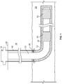
- FIG. 1 illustrates an example well system 10 including a plurality of well screen assemblies 12.
- the well system 10 is shown as being a horizontal well, having a wellbore 14 that deviates to horizontal or substantially horizontal in the subterranean zone of interest 24.
- a casing 16 is cemented in the vertical portion of the wellbore and coupled to a wellhead 18 at the surface 20.
- the remainder of the wellbore 14 is completed open hole (i.e., without casing).
- a production string 22 extends from wellhead 18, through the wellbore 14 and into the subterranean zone of interest 24.
- a production packer 28 seals the annulus between the production string 22 and the casing 16.
- the production string 22 operates in producing fluids (e.g., oil, gas, and/or other fluids) from the subterranean zone 24 to the surface 20.
- the production string 22 includes one or more well screen assemblies 12 (two shown).
- the annulus between the production string 22 and the open hole portion of the wellbore 14 may be packed with gravel and/or sand (hereinafter referred to as gravel packing 26 for convenience).
- the well screen assemblies 12 and gravel packing 26 allow communication of fluids between the production string 22 and subterranean zone 24.
- the gravel packing 26 provides a first stage of filtration against passage of particulate and larger fragments of the formation to the production string 22.
- the well screen assemblies provide a second stage of filtration, and are configured to filter against passage of particulate of a specified size and larger into the production string 22.
- well screen assemblies 12 can be provided in other well configurations, including vertical well systems having a vertical or substantial vertical wellbore, multi-lateral well systems having multiple wellbores deviating from a common wellbore and/or other well systems. Also, although described in a production context, well screen assemblies 12 can be used in other contexts, including injection, well treatment and/or other applications.
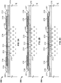
- FIGS. 2A-2C are half side cross-sectional views of a well screen assembly 200 constructed in accordance with the concepts described herein.
- the well screen assembly 200 includes an elongate tubular base pipe 210 that carries a wrapped-on-pipe screen layer 220.
- the base pipe has a plurality of apertures 212 between the interior and exterior of the base pipe to allow communication of fluid between the interior and the exterior.
- the ends of the base pipe 210 are adapted to couple to other tubulars of a well string (e.g., by box and pin and/or otherwise).
- the wrapped-on-pipe screen layer 220 is a type of screen formed by wrapping a wire 214 helically around the exterior of the base pipe 210.
- an axial rib 215 is provided between the screen layer 220 and the base pipe 210 when the wire 214 is wrapped around the exterior of the base pipe 210.
- the wire 214 can be welded to the rib 215 as it is wrapped.
- the screen layer 220 functions to filter against passage of particulate of a specified size and larger into the interior of the base pipe 210.
- the pitch of the helix is selected such that the space between adjacent turns of wire 214 at the location where the wire 214 turns are closest together is at least smaller than the specified size of the particulate.
- the screen layer 220 can filter against passage of gravel and/or sand sized particulate.
- the wire 214 can take the form of a number of different shapes.
- the wire 214 is trapezoidal in axial cross-section, having a larger transverse dimension at the outer surface of the screen layer 220 than at the inner surface of the screen layer 220.
- the wire 214 can have other different shapes, including triangular, circular, elliptical, square, and other shapes.
- the screen assembly 200 is formed by wrapping the wire 214 helically around the exterior of the base pipe 210. Then, a end ring 216 is placed on the base pipe 210, encircling the base pipe 210 and adjacent, and in some instances adjacent and contacting, the end of the screen layer 220. In certain instances, the end ring 216 can be a continuous ring. In certain instances the end ring 216 can be split such that the end ring can be opened and placed laterally over the base pipe 210, rather than requiring the end ring to be introduced over the end of the base pipe 210 and passed over the base pipe 210 into position.
- the end ring 216 when split, need not account for irregularities (e.g., ovality, thickness and diameter variations, and other irregularities) over the entire or other length of the base pipe 210, because it need not pass over the length of the base pipe 210. Furthermore, in certain instances, it can be more convenient to place the end ring 216 laterally over the base pipe 210 when, for example, the screen layer 220 terminates intermediate a length of the base pipe 210 rather than adjacent an end.
- irregularities e.g., ovality, thickness and diameter variations, and other irregularities
- the split end ring 216 can be two or more arcuate, C-shaped ring segments 216a, 216b as in FIG. 3A that are assembled around the base pipe 210.
- the end ring 216 can be a substantially complete ring with a single cut to allow the end ring 216 to be opened and the base pipe 210 received through the cut.
- a notch or partial cut can be provided opposite the single cut to facilitate opening the end ring 216.
- Other configurations are likewise possible.
- the outer diameter of the end ring 216 when assembled around the base pipe 210, is equal to or slightly smaller than the outer diameter of the screen layer 220.
- the inner diameter of the split ring 216 is equal to or slightly larger than the outer diameter of the base pipe 210.
- the inner diameter of the split ring 216 can be a loose fit over the base pipe 210 to accommodate variations in the base pipe 210 outer diameter, ovality, and/or other irregularities of the base pipe 210.
- the end ring 216 is secured to the base pipe and/or the screen layer 220.
- the end ring 216 is tack welded to the base pipe 210 and/or the screen layer 220. Tack welding is a technique where short segments or points of weld are applied at spaced out intervals, rather than a continuous or a long stitch weld.
- the end ring 216 can be clamped, secured by fasteners, secured with adhesive, and/or secured another manner.
- the end ring 216 need not be permanently and strongly secured to the base pipe 210, because as is discussed below, the end ring 216 will be further secured to the base pipe in a later construction step.
- the end ring 216 is provided with a weld bevel 217 opposite the surface facing the screen layer 220 to facilitate formation of a weld bead between the end ring 216 and the outer surface of the base pipe 210.
- a crimp ring 218 ( FIG. 3B ) is positioned encircling and over the interface between the end ring 216 and the screen layer 220, such that a portion of the crimp ring 218 resides over the end of the screen layer 220 and a portion of the crimp ring 218 resides over the end ring 216.
- the crimp ring 218 can overlap the screen layer 220 by 1-2 inches or more. In certain instances, the crimp ring 218 can overlap the screen layer 220 by less.
- the crimp ring 218 can be a loose fit over the base pipe 210 to accommodate variations in the screen layer 220 outer diameter, ovality, and/or other irregularities of the screen layer 220, and allow the crimp ring 218 to be received over the end of the screen layer 220 and moved over the screen layer into location. Once in position, the crimp ring 218 is crimped, i.e., plastically deformed, into close relationship and/or contact with the outer surface of the screen layer 220 and the split ring 216 (compare FIGS. 2B and 2C ). In certain instances, to prevent passage of the specified size particulate, it is desirable to crimp the crimp ring 218 into continuous contact around the entire circumference of the screen layer 220.
- all or a portion of the crimp ring 218 can be crimped to close, but spaced apart proximity to the screen layer 220 with a largest radial gap between the crimp ring 218 and screen layer 220 being at least smaller than the specified size of particulate filtered by the screen layer 220.
- the crimp ring 218, end ring 216 and base pipe 210 are welded together by forming one or more beads of weld 222 circumferentially around and contacting the interface between the crimp ring 218 and the end ring 216 and the interface between the end ring 216 and the base pipe 210 as shown in FIG. 2A .
- the beads of weld 222 can be deposited by welding, brazing, soldering, as polymer epoxy and/or other means. Welding is joining the materials by coalescing the materials and/or a filler material. Brazing and soldering, in the context of metallic components, are joining the metals without coalescing the materials.
- the beads of weld 222 can be continuous and seal against passage of the specified size of particulate and/or fluid between the crimp ring 218 and end ring 216 interface and between the end ring 216 and base pipe 210, and secures the end ring 216, crimp ring 218 and screen layer 220 to the base pipe 210.
- an O-ring can additionally or alternately be provided between crimp ring 28 and end ring 216 and/or the base pipe 210 and the end ring 216 to seal against passage of the specified size of particulate and/or fluid.
- a similar or identical assembly of crimp ring 218 and end ring 216 can be installed on opposing ends of the screen layer 220.
- the crimp rings 218 and end rings 216 then bracket the screen layer 220 and retain the screen layer 220 from axially moving on the base pipe 210, as well as prevent specified size particulate from passing between the base pipe 210 and screen layer 220 at the ends of the screen layer 220.
- the screen layer 220 can be made of materials that cannot be welded or readily welded with the materials of the base pipe 210 and crimp ring 218.
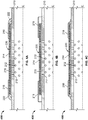
- FIGS. 4A-4C are half side cross-sectional views of another well screen assembly 400 constructed in accordance with the concepts described herein.
- the well screen assembly 400 includes a base pipe 210, a screen layer 220 formed of wire 214 helically wrapped around the base pipe 210, and a crimp ring 218.
- the end ring 216 is omitted and the crimp ring 218 is configured with enough material that it can be crimped both to the outer surface of the screen layer 220 and to the outer surface of the base pipe 210.
- the crimp ring 218 is welded to the base pipe 210 by forming beads of weld circumferentially around and contacting the interface between the crimp ring 218 and the base pipe 210.
Landscapes
- Engineering & Computer Science (AREA)
- Mining & Mineral Resources (AREA)
- Geology (AREA)
- Life Sciences & Earth Sciences (AREA)
- Fluid Mechanics (AREA)
- Environmental & Geological Engineering (AREA)
- Chemical & Material Sciences (AREA)
- Physics & Mathematics (AREA)
- Dispersion Chemistry (AREA)
- General Life Sciences & Earth Sciences (AREA)
- Geochemistry & Mineralogy (AREA)
- Filtering Materials (AREA)
- Filtration Of Liquid (AREA)
- Protection Of Pipes Against Damage, Friction, And Corrosion (AREA)
- Wire Processing (AREA)
Description
- This application claims priority under 35 U.S.C. §119 to
U.S. Patent Application Serial No. 12/855,932, filed August 13, 2010 - This description relates to filtration apparatus for use in subterranean wellbores.
- For centuries, wells have been drilled to extract oil, natural gas, water, and other fluids from subterranean formations. In extracting the fluids, a production string is provided in a wellbore, both reinforcing the structural integrity of the wellbore, as well as assisting in extraction of fluids from the well. To allow fluids to flow into production string, apertures are often provided in the tubing string in the section of the string corresponding with production zones of the well. Although perforations allow for ingress of the desired fluids from the formation, these perforations can also allow unwanted materials to flow into the well from the surrounding foundations during production. Debris, such as formation sand and other particulate, can fall or be swept into the tubing together with formation fluid, contaminating the recovered fluid. Not only do sand and other particulates contaminate the recovered fluid, this particulate can cause many additional problems for the well operator. For example, as the particulate flows through production equipment, it gradually erodes the equipment, accumulate in chambers, and block flow passages. Repairing and replacing production equipment damaged by particulate in-flow can be costly and time-consuming, particularly for downhole equipment sometimes located several thousand feet below the Earth's surface. Consequently, to guard against particulate from entering production equipment, while at the same time preserving sufficient fluid flow pathways, various production filters and filtration methods have been developed and employed including gravel packs and well screen assemblies.
- A number of well screen filtration designs have been employed. A well screen assembly is a screen of one or more layers installed in the well, capable of filtering against passage of particulate of a specified size and larger, such as sand, rock fragments and gravel from surrounding gravel packing. The specific design of the well screen can take into account the type of subterranean formation likely to be encountered, as well as the well-type.
A prior art well screen is disclosed inWO2010118143 , wherein awell screen assembly 12 includes an elongate base pipe 160 and a wire wrap layer 130. The wire wrap layer includes a wire 135 wrapped around support ribs 105. The wire wrap layer has an axial end section 305 wrapped at a first gage and an intermediate section 310 wrapped at a second, larger gage. A mesh layer is provided around the wire wrap layer. An outer shroud 195 is provided around the mesh layer, the outer shroud sealed to the wire wrap layer.US5611399 discloses a well screen assembly withbase pipe 10,screen 14 and end cap 58 which is screwed to endring 26. - This description relates to filtration apparatus for use in subterranean wellbores, for example, well screen assemblies.
- According to the present invention there is provided a well screen as defined in the appended claim 1. Further preferable features of the well screen of the present invention are defined in the appended dependent apparatus claims.
- According to the present invention there is also provided a method for constructing a well screen as defined in the appended method claim. Further preferable features of the method for constructing a well screen of the present invention are defined in the appended dependent method claims.
- In certain aspects, a well screen assembly has an elongate tubular base pipe defining apertures extending between the interior and exterior of the base pipe. A screen layer is carried on the base pipe and includes a wire that has been wrapped helically around the exterior of the base pipe. A crimp ring is affixed to the base pipe and encircles the base pipe and an end of the screen layer. The crimp ring is plastically deformed about an outer surface of the screen layer.
- In certain aspects, a method for constructing a well screen assembly includes positioning a crimp ring encircling and over an end of a wrapped-on-pipe screen layer on a tubular base pipe. The crimp ring is plastically deformed about an outer surface of the screen layer. Weld is applied to affix the crimp ring to the base pipe.
- In certain aspects, a method includes wrapping a wire helically around a base pipe to define a screen layer. A crimp ring is introduced over an end of the screen layer. The crimp ring is plastically deformed around the screen layer and securing the screen layer to the base pipe.
- One or more of the aspects include some, none or all of the following features. In certain instances, an end ring is affixed to the base pipe and encircles the base pipe. The crimp ring is plastically deformed about an outer surface of the end ring. The crimp ring is welded to the end ring, and the end ring is welded to the base pipe. The end ring is continuous or split. In certain instances, the split end ring includes a plurality of arcuate ring segments assembled about the base pipe. In certain instances, the end ring is omitted and the crimp ring is welded to the base pipe. The crimp ring is deformed into contact with the outer surface of the screen layer. In certain instances, the material of the screen layer and the material of the base pipe are incompatible for welding. In certain instances, a second crimp ring is affixed to the base pipe and encircles the base pipe and a second end of the screen layer, the second crimp ring plastically deformed about the outer surface of the screen layer.
- The details of one or more implementations are set forth in the accompanying drawings and the description below. Other features, objects, and advantages will be apparent from the description and drawings, and from the claims.
-
-
FIG. 1 is a side cross-sectional view of an example well system including a plurality of well screen assemblies constructed in accordance with the concepts described herein. -
FIGS. 2A-2C are half side cross-sectional views of a well screen assembly constructed in accordance with the concepts described herein, whereinFIG. 2A illustrates the completed well screen assembly,FIG. 2B illustrates the well screen assembly prior to crimping, andFIG. 2C illustrates the well screen assembly after crimping. -
FIG. 3A is a perspective view of an end ring constructed in accordance with the concepts described herein. -
FIG. 3B is a perspective view of a crimp ring constructed in accordance with the concepts described herein. -
FIGS. 4A-4C are half side cross-sectional views of another well screen assembly constructed in accordance with the concepts described herein, whereinFIG. 4A illustrates the completed well screen assembly,FIG. 4B illustrates the well screen assembly prior to crimping, andFIG. 4C illustrates the well screen assembly after crimping. - Like reference symbols in the various drawings indicate like elements.
-
FIG. 1 illustrates anexample well system 10 including a plurality ofwell screen assemblies 12. Thewell system 10 is shown as being a horizontal well, having awellbore 14 that deviates to horizontal or substantially horizontal in the subterranean zone ofinterest 24. Acasing 16 is cemented in the vertical portion of the wellbore and coupled to awellhead 18 at thesurface 20. The remainder of thewellbore 14 is completed open hole (i.e., without casing). Aproduction string 22 extends fromwellhead 18, through thewellbore 14 and into the subterranean zone ofinterest 24. Aproduction packer 28 seals the annulus between theproduction string 22 and thecasing 16. Theproduction string 22 operates in producing fluids (e.g., oil, gas, and/or other fluids) from thesubterranean zone 24 to thesurface 20. Theproduction string 22 includes one or more well screen assemblies 12 (two shown). In some instances, the annulus between theproduction string 22 and the open hole portion of thewellbore 14 may be packed with gravel and/or sand (hereinafter referred to as gravel packing 26 for convenience). Thewell screen assemblies 12 and gravel packing 26 allow communication of fluids between theproduction string 22 andsubterranean zone 24. The gravel packing 26 provides a first stage of filtration against passage of particulate and larger fragments of the formation to theproduction string 22. The well screen assemblies provide a second stage of filtration, and are configured to filter against passage of particulate of a specified size and larger into theproduction string 22. - Although shown in the context of a
horizontal well system 10, well screenassemblies 12 can be provided in other well configurations, including vertical well systems having a vertical or substantial vertical wellbore, multi-lateral well systems having multiple wellbores deviating from a common wellbore and/or other well systems. Also, although described in a production context, well screenassemblies 12 can be used in other contexts, including injection, well treatment and/or other applications. -
FIGS. 2A-2C are half side cross-sectional views of awell screen assembly 200 constructed in accordance with the concepts described herein. Thewell screen assembly 200 includes an elongatetubular base pipe 210 that carries a wrapped-on-pipe screen layer 220. The base pipe has a plurality ofapertures 212 between the interior and exterior of the base pipe to allow communication of fluid between the interior and the exterior. In certain instances, the ends of thebase pipe 210 are adapted to couple to other tubulars of a well string (e.g., by box and pin and/or otherwise). The wrapped-on-pipe screen layer 220 is a type of screen formed by wrapping awire 214 helically around the exterior of thebase pipe 210. In certain instances, anaxial rib 215 is provided between thescreen layer 220 and thebase pipe 210 when thewire 214 is wrapped around the exterior of thebase pipe 210. Thewire 214 can be welded to therib 215 as it is wrapped. Thescreen layer 220 functions to filter against passage of particulate of a specified size and larger into the interior of thebase pipe 210. Thus, in certain instances, the pitch of the helix is selected such that the space between adjacent turns ofwire 214 at the location where thewire 214 turns are closest together is at least smaller than the specified size of the particulate. In certain instances, thescreen layer 220 can filter against passage of gravel and/or sand sized particulate. Thewire 214 can take the form of a number of different shapes. For example, inFIG. 2A , thewire 214 is trapezoidal in axial cross-section, having a larger transverse dimension at the outer surface of thescreen layer 220 than at the inner surface of thescreen layer 220. In other instances, thewire 214 can have other different shapes, including triangular, circular, elliptical, square, and other shapes. - The
screen assembly 200 is formed by wrapping thewire 214 helically around the exterior of thebase pipe 210. Then, aend ring 216 is placed on thebase pipe 210, encircling thebase pipe 210 and adjacent, and in some instances adjacent and contacting, the end of thescreen layer 220. In certain instances, theend ring 216 can be a continuous ring. In certain instances theend ring 216 can be split such that the end ring can be opened and placed laterally over thebase pipe 210, rather than requiring the end ring to be introduced over the end of thebase pipe 210 and passed over thebase pipe 210 into position. In certain instances, theend ring 216, when split, need not account for irregularities (e.g., ovality, thickness and diameter variations, and other irregularities) over the entire or other length of thebase pipe 210, because it need not pass over the length of thebase pipe 210. Furthermore, in certain instances, it can be more convenient to place theend ring 216 laterally over thebase pipe 210 when, for example, thescreen layer 220 terminates intermediate a length of thebase pipe 210 rather than adjacent an end. - The
split end ring 216 can be two or more arcuate, C-shapedring segments FIG. 3A that are assembled around thebase pipe 210. In other instances, theend ring 216 can be a substantially complete ring with a single cut to allow theend ring 216 to be opened and thebase pipe 210 received through the cut. A notch or partial cut can be provided opposite the single cut to facilitate opening theend ring 216. Other configurations are likewise possible. In certain instances, the outer diameter of theend ring 216, when assembled around thebase pipe 210, is equal to or slightly smaller than the outer diameter of thescreen layer 220. The inner diameter of thesplit ring 216 is equal to or slightly larger than the outer diameter of thebase pipe 210. The inner diameter of thesplit ring 216 can be a loose fit over thebase pipe 210 to accommodate variations in thebase pipe 210 outer diameter, ovality, and/or other irregularities of thebase pipe 210. - The
end ring 216 is secured to the base pipe and/or thescreen layer 220. In certain instances, theend ring 216 is tack welded to thebase pipe 210 and/or thescreen layer 220. Tack welding is a technique where short segments or points of weld are applied at spaced out intervals, rather than a continuous or a long stitch weld. In other instances, theend ring 216 can be clamped, secured by fasteners, secured with adhesive, and/or secured another manner. Theend ring 216 need not be permanently and strongly secured to thebase pipe 210, because as is discussed below, theend ring 216 will be further secured to the base pipe in a later construction step. In certain instances, theend ring 216 is provided with aweld bevel 217 opposite the surface facing thescreen layer 220 to facilitate formation of a weld bead between theend ring 216 and the outer surface of thebase pipe 210. - A crimp ring 218 (
FIG. 3B ) is positioned encircling and over the interface between theend ring 216 and thescreen layer 220, such that a portion of thecrimp ring 218 resides over the end of thescreen layer 220 and a portion of thecrimp ring 218 resides over theend ring 216. In certain instances, thecrimp ring 218 can overlap thescreen layer 220 by 1-2 inches or more. In certain instances, thecrimp ring 218 can overlap thescreen layer 220 by less. Thecrimp ring 218 can be a loose fit over thebase pipe 210 to accommodate variations in thescreen layer 220 outer diameter, ovality, and/or other irregularities of thescreen layer 220, and allow thecrimp ring 218 to be received over the end of thescreen layer 220 and moved over the screen layer into location. Once in position, thecrimp ring 218 is crimped, i.e., plastically deformed, into close relationship and/or contact with the outer surface of thescreen layer 220 and the split ring 216 (compareFIGS. 2B and 2C ). In certain instances, to prevent passage of the specified size particulate, it is desirable to crimp thecrimp ring 218 into continuous contact around the entire circumference of thescreen layer 220. In certain instances, to prevent passage of the specified size particulate, all or a portion of thecrimp ring 218 can be crimped to close, but spaced apart proximity to thescreen layer 220 with a largest radial gap between thecrimp ring 218 andscreen layer 220 being at least smaller than the specified size of particulate filtered by thescreen layer 220. - Thereafter, the
crimp ring 218,end ring 216 andbase pipe 210 are welded together by forming one or more beads ofweld 222 circumferentially around and contacting the interface between thecrimp ring 218 and theend ring 216 and the interface between theend ring 216 and thebase pipe 210 as shown inFIG. 2A . The beads ofweld 222 can be deposited by welding, brazing, soldering, as polymer epoxy and/or other means. Welding is joining the materials by coalescing the materials and/or a filler material. Brazing and soldering, in the context of metallic components, are joining the metals without coalescing the materials. The beads ofweld 222 can be continuous and seal against passage of the specified size of particulate and/or fluid between thecrimp ring 218 andend ring 216 interface and between theend ring 216 andbase pipe 210, and secures theend ring 216,crimp ring 218 andscreen layer 220 to thebase pipe 210. In certain instances, an O-ring can additionally or alternately be provided betweencrimp ring 28 andend ring 216 and/or thebase pipe 210 and theend ring 216 to seal against passage of the specified size of particulate and/or fluid. A similar or identical assembly ofcrimp ring 218 andend ring 216 can be installed on opposing ends of thescreen layer 220. The crimp rings 218 and end rings 216 then bracket thescreen layer 220 and retain thescreen layer 220 from axially moving on thebase pipe 210, as well as prevent specified size particulate from passing between thebase pipe 210 andscreen layer 220 at the ends of thescreen layer 220. - Because the
base pipe 210 andcrimp ring 218 need not be welded to thescreen layer 220, thescreen layer 220 can be made of materials that cannot be welded or readily welded with the materials of thebase pipe 210 andcrimp ring 218. -
FIGS. 4A-4C are half side cross-sectional views of anotherwell screen assembly 400 constructed in accordance with the concepts described herein. As with thewell screen assembly 200 described above, thewell screen assembly 400 includes abase pipe 210, ascreen layer 220 formed ofwire 214 helically wrapped around thebase pipe 210, and acrimp ring 218. However, theend ring 216 is omitted and thecrimp ring 218 is configured with enough material that it can be crimped both to the outer surface of thescreen layer 220 and to the outer surface of thebase pipe 210. Thereafter, thecrimp ring 218 is welded to thebase pipe 210 by forming beads of weld circumferentially around and contacting the interface between thecrimp ring 218 and thebase pipe 210.
Claims (14)
- A well screen assembly (12), comprising:an elongate tubular base pipe (210) defining apertures extending between the interior and exterior of the base pipe (210);a screen layer (220) carried on the base pipe (210) and comprising a wire (214) that has been wrapped helically around the exterior of the base pipe (210); anda crimp ring (218) not welded to the screen layer (220) and affixed to the base pipe (210) and encircling the base pipe (210) and an end of the screen layer (220), the crimp ring (218) plastically deformed about an outer surface of the screen layer (220),an end ring (216) affixed to the base pipe (210) and encircling the base pipe (210), and characterized in that the crimp ring (218) is plastically deformed about an outer surface of the end ring (216), and in that an O-ring is provided between the crimp ring (218) and the end ring (216) and/or between the base pipe (210) and the end ring (216) to seal against passage of a specified size of particulate and/or fluid.
- A well screen assembly (12) of claim 1, wherein the crimp ring (218) is welded to the end ring (216), and the end ring (216) is welded to the base pipe (210).
- A well screen assembly (12) of claim 1, wherein the end ring (216) is split.
- A well screen assembly (12) of claim 3, wherein the end ring (216) comprises a plurality of arcuate ring segments (216a, 216b) assembled about the base pipe (210).
- A well screen assembly (12) of claim 1, wherein the crimp ring (218) is welded to the base pipe (210).
- A well screen assembly (12) of claim 1, wherein the crimp ring (218) is deformed into contact with the outer surface of the screen layer (220).
- A well screen assembly (12) of claim 1, wherein a material of the screen layer (220) and a material of the base pipe (210) are incompatible for welding.
- A well screen assembly (12) of claim 1 or further comprising a second crimp ring affixed to the base pipe (210) and encircling the base pipe (210) and a second end of the screen layer (220), the second crimp ring plastically deformed about the outer surface of the screen layer (220).
- A method for constructing a well screen (12), comprising:positioning a crimp ring (218) encircling and over an end of a wrapped-on-pipe screen layer (220) on a tubular base pipe (210);plastically deforming the crimp ring (218) about an outer surface of the screen layer (220) and securing the crimp ring (218) about the outer surface of the screen layer (220) without welding the crimp ring (218) to the screen layer (220);applying a bead of weld to affix the crimp ring (218) to the base pipe (210),positioning an end ring (216) affixed to the base pipe (210) and encircling the base pipe (210), and characterized byplastically deforming the crimp ring (218) about an outer surface of the end ring (216), andpositioning an O-ring between the crimp ring (218) and the end ring (216) and or the base pipe (210) and the end ring (216) to seal against passage of a specified size of particulate and/or fluid.
- A method of claim 9, wherein applying beads of weld to affix the crimp ring (218) to the base pipe (210) comprises welding the crimp ring (218) to the end ring (216), and welding the end ring (216) to the base pipe (210).
- A method of claim 9 wherein the end ring (216) is split and positioning the end ring (216) encircling the base pipe (210) comprises passing the end ring (216) laterally over the base pipe (210).
- A method of claim 9 wherein the end ring (216) comprises a plurality of arcuate ring segments (216a, 216b), and positioning the end ring (216) encircling the base pipe (210) comprises assembling the end ring segments (216a, 216b) around the base pipe (210).
- A method of claim 9, wherein plastically deforming the crimp ring (218) about an outer surface of the screen layer (220) comprises plastically deforming the crimp ring (218) into contact with the outer surface of the screen layer (220).
- A method of claim 9, further comprising:positioning a second crimp ring encircling and over a second end of the screen layer (220);plastically deforming the second crimp ring about the outer surface of the screen layer (220); andapplying a bead of weld to affix the second crimp ring to the base pipe (210).
Priority Applications (1)
| Application Number | Priority Date | Filing Date | Title |
|---|---|---|---|
| EP19164564.7A EP3527778A1 (en) | 2010-08-13 | 2011-08-05 | Crimped end wrapped on pipe well screen |
Applications Claiming Priority (2)
| Application Number | Priority Date | Filing Date | Title |
|---|---|---|---|
| US12/855,932 US8291971B2 (en) | 2010-08-13 | 2010-08-13 | Crimped end wrapped on pipe well screen |
| PCT/US2011/046731 WO2012021397A1 (en) | 2010-08-13 | 2011-08-05 | Crimped end wrapped on pipe well screen |
Related Child Applications (2)
| Application Number | Title | Priority Date | Filing Date |
|---|---|---|---|
| EP19164564.7A Division-Into EP3527778A1 (en) | 2010-08-13 | 2011-08-05 | Crimped end wrapped on pipe well screen |
| EP19164564.7A Division EP3527778A1 (en) | 2010-08-13 | 2011-08-05 | Crimped end wrapped on pipe well screen |
Publications (3)
| Publication Number | Publication Date |
|---|---|
| EP2603663A1 EP2603663A1 (en) | 2013-06-19 |
| EP2603663A4 EP2603663A4 (en) | 2017-04-26 |
| EP2603663B1 true EP2603663B1 (en) | 2019-05-01 |
Family
ID=45563957
Family Applications (2)
| Application Number | Title | Priority Date | Filing Date |
|---|---|---|---|
| EP19164564.7A Withdrawn EP3527778A1 (en) | 2010-08-13 | 2011-08-05 | Crimped end wrapped on pipe well screen |
| EP11816856.6A Not-in-force EP2603663B1 (en) | 2010-08-13 | 2011-08-05 | Crimped end wrapped on pipe well screen |
Family Applications Before (1)
| Application Number | Title | Priority Date | Filing Date |
|---|---|---|---|
| EP19164564.7A Withdrawn EP3527778A1 (en) | 2010-08-13 | 2011-08-05 | Crimped end wrapped on pipe well screen |
Country Status (9)
| Country | Link |
|---|---|
| US (1) | US8291971B2 (en) |
| EP (2) | EP3527778A1 (en) |
| CN (1) | CN103189597B (en) |
| AU (1) | AU2011289643B2 (en) |
| BR (1) | BR112013003036B1 (en) |
| CA (1) | CA2807486C (en) |
| MY (1) | MY165465A (en) |
| SG (1) | SG187804A1 (en) |
| WO (1) | WO2012021397A1 (en) |
Families Citing this family (19)
| Publication number | Priority date | Publication date | Assignee | Title |
|---|---|---|---|---|
| US9556994B2 (en) * | 2009-06-30 | 2017-01-31 | Antelope Oil Tool & Mfg. Co. | Wrap-around band and sleeve attachment apparatus for an oilfield tubular |
| US20120073801A1 (en) * | 2010-09-23 | 2012-03-29 | Halliburton Energy Services, Inc. | Sand Control Screen Assembly Having a Mechanically Attached Screen Jacket |
| US8602096B2 (en) | 2011-06-28 | 2013-12-10 | Weatherford/Lamb, Inc. | Multiple sectioned wire-wrapped screens |
| AU2014259558B2 (en) * | 2011-06-28 | 2016-10-27 | Weatherford/Lamb, Inc. | Multiple sectioned wire-wrapped screens |
| CN104395554A (en) * | 2012-06-29 | 2015-03-04 | 哈利伯顿能源服务公司 | Isolation assembly for inflow control device |
| US9556687B2 (en) | 2013-08-17 | 2017-01-31 | Antelope Oil Tool & Mfg. Co. | Multi-vane centralizer and method of forming |
| US9765576B2 (en) | 2013-08-17 | 2017-09-19 | Antelope Oil Tool & Mfg. Co. | Wrap-around stop collar and method of forming |
| GB2539819B (en) | 2014-05-09 | 2020-09-16 | Halliburton Energy Services Inc | Sealing rings for a wire wrapped screen of a sand screen assembly |
| US10376947B2 (en) | 2014-12-30 | 2019-08-13 | Baker Hughes, A Ge Company, Llc | Multiple wire wrap screen fabrication method |
| US10000993B2 (en) | 2015-04-29 | 2018-06-19 | Baker Hughes, A Ge Company, Llc | Multi-gauge wrap wire for subterranean sand screen |
| CN106166410B (en) * | 2016-08-04 | 2018-10-12 | 荆州市宏泉井业节能科技有限公司 | A kind of moso bamboo filter for water supply well |
| AR109803A1 (en) * | 2016-10-04 | 2019-01-23 | Rgl Reservoir Man Inc | WIRE SIZE ASSEMBLY AND METHOD FOR THE SAME |
| US11613969B2 (en) * | 2017-07-20 | 2023-03-28 | Baker Hughes Holdings Llc | Skive cut borehole screen end ring method of use |
| US20190024486A1 (en) * | 2017-07-20 | 2019-01-24 | Baker Hughes, A Ge Company, Llc | Skive Cut Borehole Screen End Ring |
| US11492876B2 (en) * | 2017-09-15 | 2022-11-08 | Halliburton Energy Services, Inc. | Sand screen system with adhesive bonding |
| RU199502U1 (en) * | 2020-06-04 | 2020-09-04 | Общество с ограниченной ответственностью «ТАТПРОМ-ХОЛДИНГ» | Downhole slotted wire strainer with direct winding on the casing |
| CN111764862A (en) * | 2020-06-29 | 2020-10-13 | 中国石油天然气集团有限公司 | Rubber cylinder end omnibearing protection end ring |
| CN111691860B (en) * | 2020-06-30 | 2022-06-28 | 承德石油高等专科学校 | High-efficient screen pipe is used in oil gas exploitation |
| US20230160285A1 (en) * | 2021-11-19 | 2023-05-25 | Baker Hughes Oilfield Operations Llc | Borehole tool and system |
Family Cites Families (65)
| Publication number | Priority date | Publication date | Assignee | Title |
|---|---|---|---|---|
| US1976217A (en) | 1933-05-02 | 1934-10-09 | Alex J Diepenbrock | Well screen |
| US3515280A (en) * | 1968-12-03 | 1970-06-02 | Watson H Parker | Stacked element filter apparatus |
| US3908256A (en) | 1972-10-31 | 1975-09-30 | Smith Co Howard | Method of making a deep well screen |
| US3958634A (en) | 1972-10-31 | 1976-05-25 | Howard Smith Company | Welded wire well screen on perforated casing |
| GB1601706A (en) | 1977-12-02 | 1981-11-04 | Bannister A S | Tubewells |
| US4428423A (en) | 1982-05-06 | 1984-01-31 | Uop Inc. | Well screen end fitting assembly and method of making same |
| US4771829A (en) | 1987-12-30 | 1988-09-20 | Sparlin Derry D | Well liner with selective isolation screen |
| GB8918581D0 (en) | 1989-08-15 | 1989-09-27 | Endless Energy Ltd | A filter element |
| US5190102A (en) | 1990-10-22 | 1993-03-02 | Otis Engineering Corporation | Sintered metal substitute for prepack screen aggregate |
| JP2891582B2 (en) * | 1991-12-27 | 1999-05-17 | 株式会社ナガオカ | Method of manufacturing selective isolation screen |
| US5310000A (en) | 1992-09-28 | 1994-05-10 | Halliburton Company | Foil wrapped base pipe for sand control |
| US5355948A (en) | 1992-11-04 | 1994-10-18 | Sparlin Derry D | Permeable isolation sectioned screen |
| US5339895A (en) | 1993-03-22 | 1994-08-23 | Halliburton Company | Sintered spherical plastic bead prepack screen aggregate |
| US5664628A (en) | 1993-05-25 | 1997-09-09 | Pall Corporation | Filter for subterranean wells |
| JPH07158124A (en) | 1993-12-02 | 1995-06-20 | Nagaoka:Kk | Screen for well having uniform outside diameter |
| US5624560A (en) | 1995-04-07 | 1997-04-29 | Baker Hughes Incorporated | Wire mesh filter including a protective jacket |
| US5642781A (en) | 1994-10-07 | 1997-07-01 | Baker Hughes Incorporated | Multi-passage sand control screen |
| UA67719C2 (en) | 1995-11-08 | 2004-07-15 | Shell Int Research | Deformable well filter and method for its installation |
| US5611399A (en) | 1995-11-13 | 1997-03-18 | Baker Hughes Incorporated | Screen and method of manufacturing |
| US5842522A (en) * | 1996-01-03 | 1998-12-01 | Halliburton Energy Services, Inc. | Mechanical connection between base pipe and screen and method for use of the same |
| NO972792L (en) * | 1996-06-20 | 1997-12-22 | Pall Corp | Filter for underground use |
| US5738170A (en) | 1996-09-03 | 1998-04-14 | United States Filter Corporation | Compact double screen assembly |
| US5938925A (en) | 1997-01-23 | 1999-08-17 | Halliburton Energy Services, Inc. | Progressive gap sand control screen and process for manufacturing the same |
| US5918672A (en) | 1997-05-08 | 1999-07-06 | Mcconnell; Howard T. | Shroud for a well screen |
| US6062307A (en) * | 1997-10-24 | 2000-05-16 | Halliburton Energy Services, Inc. | Screen assemblies and methods of securing screens |
| US5979551A (en) | 1998-04-24 | 1999-11-09 | United States Filter Corporation | Well screen with floating mounting |
| US6315040B1 (en) | 1998-05-01 | 2001-11-13 | Shell Oil Company | Expandable well screen |
| US6092604A (en) | 1998-05-04 | 2000-07-25 | Halliburton Energy Services, Inc. | Sand control screen assembly having a sacrificial anode |
| DE69906109T2 (en) | 1998-10-05 | 2003-12-18 | Cuno Inc., Meriden | FILTER AND METHOD FOR FILTRATING A FLUID |
| US6305468B1 (en) | 1999-05-28 | 2001-10-23 | Baker Hughes Incorporated | Downhole screen and method of manufacture |
| US6415509B1 (en) | 2000-05-18 | 2002-07-09 | Halliburton Energy Services, Inc. | Methods of fabricating a thin-wall expandable well screen assembly |
| US6530431B1 (en) | 2000-06-22 | 2003-03-11 | Halliburton Energy Services, Inc. | Screen jacket assembly connection and methods of using same |
| US6715544B2 (en) | 2000-09-29 | 2004-04-06 | Weatherford/Lamb, Inc. | Well screen |
| GB2371319B (en) | 2001-01-23 | 2003-08-13 | Schlumberger Holdings | Completion Assemblies |
| GB0104486D0 (en) | 2001-02-23 | 2001-04-11 | Cross Mfg Co 1938 Ltd | An improved filter element |
| US20020189808A1 (en) | 2001-06-13 | 2002-12-19 | Nguyen Philip D. | Methods and apparatus for gravel packing or frac packing wells |
| US6581689B2 (en) * | 2001-06-28 | 2003-06-24 | Halliburton Energy Services, Inc. | Screen assembly and method for gravel packing an interval of a wellbore |
| US6612481B2 (en) | 2001-07-30 | 2003-09-02 | Weatherford/Lamb, Inc. | Wellscreen |
| US6830104B2 (en) | 2001-08-14 | 2004-12-14 | Halliburton Energy Services, Inc. | Well shroud and sand control screen apparatus and completion method |
| US6857475B2 (en) | 2001-10-09 | 2005-02-22 | Schlumberger Technology Corporation | Apparatus and methods for flow control gravel pack |
| US6899176B2 (en) | 2002-01-25 | 2005-05-31 | Halliburton Energy Services, Inc. | Sand control screen assembly and treatment method using the same |
| JP2003342977A (en) | 2002-05-27 | 2003-12-03 | Tadayoshi Nagaoka | Spreadable screen for horizontal well and for inclined well and its execution method |
| US7287684B2 (en) | 2002-07-03 | 2007-10-30 | Tubular Perforating Mfg., Ltd. | Filter cartridge assembly and method of manufacture |
| US20040026313A1 (en) | 2002-08-09 | 2004-02-12 | Arlon Fischer Todd Kenneth | Multi-micron, multi-zoned mesh, method of making and use thereof |
| EP1644610B1 (en) | 2003-06-17 | 2018-09-26 | Completion Products Pte Ltd | A well screen |
| US20050014429A1 (en) | 2003-07-16 | 2005-01-20 | Ruediger Tueshaus | Wire mesh panel and method |
| US20050126779A1 (en) | 2003-12-10 | 2005-06-16 | The Cavins Corporation | Seamless woven wire sintered well screen |
| US20060186601A1 (en) | 2005-02-18 | 2006-08-24 | Jean-Marc Lopez | Fluid seals |
| US20070012444A1 (en) | 2005-07-12 | 2007-01-18 | John Horgan | Apparatus and method for reducing water production from a hydrocarbon producing well |
| US20070199889A1 (en) | 2006-02-27 | 2007-08-30 | Ruediger Tueshaus | Tubular filter material assemblies and methods |
| US7497257B2 (en) | 2006-05-04 | 2009-03-03 | Purolator Facet, Inc. | Particle control screen with depth filtration |
| US20080035330A1 (en) | 2006-08-10 | 2008-02-14 | William Mark Richards | Well screen apparatus and method of manufacture |
| US20080283239A1 (en) | 2007-05-14 | 2008-11-20 | Schlumberger Technology Corporation | Well screen with diffusion layer |
| US20080289815A1 (en) | 2007-05-22 | 2008-11-27 | Schlumberger Technology Corporation | Downhole screen assembly |
| US7578343B2 (en) * | 2007-08-23 | 2009-08-25 | Baker Hughes Incorporated | Viscous oil inflow control device for equalizing screen flow |
| US7775284B2 (en) | 2007-09-28 | 2010-08-17 | Halliburton Energy Services, Inc. | Apparatus for adjustably controlling the inflow of production fluids from a subterranean well |
| US8267169B2 (en) | 2008-03-13 | 2012-09-18 | Schlumberger Technology Corporation | Methods and apparatus for attaching accessories to sand screen assemblies |
| US8176634B2 (en) * | 2008-07-02 | 2012-05-15 | Halliburton Energy Services, Inc. | Method of manufacturing a well screen |
| US7841409B2 (en) | 2008-08-29 | 2010-11-30 | Halliburton Energy Services, Inc. | Sand control screen assembly and method for use of same |
| US8127447B2 (en) | 2008-11-19 | 2012-03-06 | Baker Hughes Incorporated | Method for downhole screen manufacturing |
| US20100163481A1 (en) | 2008-12-30 | 2010-07-01 | Dorstener Wire Tech | Drainage or Filter Layer for Well Screen Assembly with Integrated Stand-off Structure |
| US8196653B2 (en) | 2009-04-07 | 2012-06-12 | Halliburton Energy Services, Inc. | Well screens constructed utilizing pre-formed annular elements |
| US8146662B2 (en) * | 2009-04-08 | 2012-04-03 | Halliburton Energy Services, Inc. | Well screen assembly with multi-gage wire wrapped layer |
| US20100258302A1 (en) | 2009-04-08 | 2010-10-14 | Halliburton Energy Services, Inc. | Well Screen With Drainage Assembly |
| US8251138B2 (en) | 2009-04-09 | 2012-08-28 | Halliburton Energy Services, Inc. | Securing layers in a well screen assembly |
-
2010
- 2010-08-13 US US12/855,932 patent/US8291971B2/en active Active
-
2011
- 2011-08-05 EP EP19164564.7A patent/EP3527778A1/en not_active Withdrawn
- 2011-08-05 AU AU2011289643A patent/AU2011289643B2/en active Active
- 2011-08-05 EP EP11816856.6A patent/EP2603663B1/en not_active Not-in-force
- 2011-08-05 CA CA2807486A patent/CA2807486C/en active Active
- 2011-08-05 MY MYPI2013000451A patent/MY165465A/en unknown
- 2011-08-05 BR BR112013003036-4A patent/BR112013003036B1/en active IP Right Grant
- 2011-08-05 CN CN201180039559.XA patent/CN103189597B/en active Active
- 2011-08-05 WO PCT/US2011/046731 patent/WO2012021397A1/en active Application Filing
- 2011-08-05 SG SG2013010129A patent/SG187804A1/en unknown
Non-Patent Citations (1)
| Title |
|---|
| None * |
Also Published As
| Publication number | Publication date |
|---|---|
| CA2807486C (en) | 2015-06-02 |
| WO2012021397A1 (en) | 2012-02-16 |
| AU2011289643B2 (en) | 2015-07-09 |
| AU2011289643A1 (en) | 2013-03-28 |
| CA2807486A1 (en) | 2012-02-16 |
| CN103189597B (en) | 2016-11-02 |
| US20120037357A1 (en) | 2012-02-16 |
| US8291971B2 (en) | 2012-10-23 |
| BR112013003036B1 (en) | 2020-03-03 |
| CN103189597A (en) | 2013-07-03 |
| EP2603663A1 (en) | 2013-06-19 |
| BR112013003036A2 (en) | 2016-06-14 |
| MY165465A (en) | 2018-03-22 |
| SG187804A1 (en) | 2013-03-28 |
| EP3527778A1 (en) | 2019-08-21 |
| EP2603663A4 (en) | 2017-04-26 |
Similar Documents
| Publication | Publication Date | Title |
|---|---|---|
| EP2603663B1 (en) | Crimped end wrapped on pipe well screen | |
| US10145221B2 (en) | Securing layers in a well screen assembly | |
| US8146662B2 (en) | Well screen assembly with multi-gage wire wrapped layer | |
| CA2859792A1 (en) | Rotating and translating shunt tube assembly | |
| SG174971A1 (en) | Well screen with drainage assembly | |
| EP2978930B1 (en) | Exterior drain tube for well screen assemblies | |
| EP2961920A1 (en) | Misalignment in coupling shunt tubes of well screen assemblies | |
| AU2016216652B2 (en) | Gravel Packing Apparatus Having Locking Jumper Tubes | |
| WO2015195101A1 (en) | Sand control filter assembly with multilayer woven wire filter mesh and method for manufacture thereof |
Legal Events
| Date | Code | Title | Description |
|---|---|---|---|
| PUAI | Public reference made under article 153(3) epc to a published international application that has entered the european phase |
Free format text: ORIGINAL CODE: 0009012 |
|
| 17P | Request for examination filed |
Effective date: 20130131 |
|
| AK | Designated contracting states |
Kind code of ref document: A1 Designated state(s): AL AT BE BG CH CY CZ DE DK EE ES FI FR GB GR HR HU IE IS IT LI LT LU LV MC MK MT NL NO PL PT RO RS SE SI SK SM TR |
|
| DAX | Request for extension of the european patent (deleted) | ||
| RA4 | Supplementary search report drawn up and despatched (corrected) |
Effective date: 20170324 |
|
| RIC1 | Information provided on ipc code assigned before grant |
Ipc: E21B 43/08 20060101AFI20170320BHEP |
|
| STAA | Information on the status of an ep patent application or granted ep patent |
Free format text: STATUS: EXAMINATION IS IN PROGRESS |
|
| 17Q | First examination report despatched |
Effective date: 20180612 |
|
| GRAP | Despatch of communication of intention to grant a patent |
Free format text: ORIGINAL CODE: EPIDOSNIGR1 |
|
| STAA | Information on the status of an ep patent application or granted ep patent |
Free format text: STATUS: GRANT OF PATENT IS INTENDED |
|
| INTG | Intention to grant announced |
Effective date: 20181123 |
|
| GRAS | Grant fee paid |
Free format text: ORIGINAL CODE: EPIDOSNIGR3 |
|
| GRAA | (expected) grant |
Free format text: ORIGINAL CODE: 0009210 |
|
| STAA | Information on the status of an ep patent application or granted ep patent |
Free format text: STATUS: THE PATENT HAS BEEN GRANTED |
|
| AK | Designated contracting states |
Kind code of ref document: B1 Designated state(s): AL AT BE BG CH CY CZ DE DK EE ES FI FR GB GR HR HU IE IS IT LI LT LU LV MC MK MT NL NO PL PT RO RS SE SI SK SM TR |
|
| REG | Reference to a national code |
Ref country code: GB Ref legal event code: FG4D |
|
| REG | Reference to a national code |
Ref country code: CH Ref legal event code: EP Ref country code: AT Ref legal event code: REF Ref document number: 1127129 Country of ref document: AT Kind code of ref document: T Effective date: 20190515 |
|
| REG | Reference to a national code |
Ref country code: DE Ref legal event code: R096 Ref document number: 602011058577 Country of ref document: DE |
|
| REG | Reference to a national code |
Ref country code: IE Ref legal event code: FG4D |
|
| REG | Reference to a national code |
Ref country code: NO Ref legal event code: T2 Effective date: 20190501 |
|
| REG | Reference to a national code |
Ref country code: NL Ref legal event code: MP Effective date: 20190501 |
|
| REG | Reference to a national code |
Ref country code: LT Ref legal event code: MG4D |
|
| PG25 | Lapsed in a contracting state [announced via postgrant information from national office to epo] |
Ref country code: PT Free format text: LAPSE BECAUSE OF FAILURE TO SUBMIT A TRANSLATION OF THE DESCRIPTION OR TO PAY THE FEE WITHIN THE PRESCRIBED TIME-LIMIT Effective date: 20190901 Ref country code: AL Free format text: LAPSE BECAUSE OF FAILURE TO SUBMIT A TRANSLATION OF THE DESCRIPTION OR TO PAY THE FEE WITHIN THE PRESCRIBED TIME-LIMIT Effective date: 20190501 Ref country code: NL Free format text: LAPSE BECAUSE OF FAILURE TO SUBMIT A TRANSLATION OF THE DESCRIPTION OR TO PAY THE FEE WITHIN THE PRESCRIBED TIME-LIMIT Effective date: 20190501 Ref country code: ES Free format text: LAPSE BECAUSE OF FAILURE TO SUBMIT A TRANSLATION OF THE DESCRIPTION OR TO PAY THE FEE WITHIN THE PRESCRIBED TIME-LIMIT Effective date: 20190501 Ref country code: LT Free format text: LAPSE BECAUSE OF FAILURE TO SUBMIT A TRANSLATION OF THE DESCRIPTION OR TO PAY THE FEE WITHIN THE PRESCRIBED TIME-LIMIT Effective date: 20190501 Ref country code: HR Free format text: LAPSE BECAUSE OF FAILURE TO SUBMIT A TRANSLATION OF THE DESCRIPTION OR TO PAY THE FEE WITHIN THE PRESCRIBED TIME-LIMIT Effective date: 20190501 Ref country code: SE Free format text: LAPSE BECAUSE OF FAILURE TO SUBMIT A TRANSLATION OF THE DESCRIPTION OR TO PAY THE FEE WITHIN THE PRESCRIBED TIME-LIMIT Effective date: 20190501 Ref country code: FI Free format text: LAPSE BECAUSE OF FAILURE TO SUBMIT A TRANSLATION OF THE DESCRIPTION OR TO PAY THE FEE WITHIN THE PRESCRIBED TIME-LIMIT Effective date: 20190501 |
|
| PGFP | Annual fee paid to national office [announced via postgrant information from national office to epo] |
Ref country code: GB Payment date: 20190610 Year of fee payment: 9 Ref country code: NO Payment date: 20190726 Year of fee payment: 9 |
|
| PG25 | Lapsed in a contracting state [announced via postgrant information from national office to epo] |
Ref country code: RS Free format text: LAPSE BECAUSE OF FAILURE TO SUBMIT A TRANSLATION OF THE DESCRIPTION OR TO PAY THE FEE WITHIN THE PRESCRIBED TIME-LIMIT Effective date: 20190501 Ref country code: LV Free format text: LAPSE BECAUSE OF FAILURE TO SUBMIT A TRANSLATION OF THE DESCRIPTION OR TO PAY THE FEE WITHIN THE PRESCRIBED TIME-LIMIT Effective date: 20190501 Ref country code: GR Free format text: LAPSE BECAUSE OF FAILURE TO SUBMIT A TRANSLATION OF THE DESCRIPTION OR TO PAY THE FEE WITHIN THE PRESCRIBED TIME-LIMIT Effective date: 20190802 Ref country code: BG Free format text: LAPSE BECAUSE OF FAILURE TO SUBMIT A TRANSLATION OF THE DESCRIPTION OR TO PAY THE FEE WITHIN THE PRESCRIBED TIME-LIMIT Effective date: 20190801 |
|
| REG | Reference to a national code |
Ref country code: AT Ref legal event code: MK05 Ref document number: 1127129 Country of ref document: AT Kind code of ref document: T Effective date: 20190501 |
|
| PG25 | Lapsed in a contracting state [announced via postgrant information from national office to epo] |
Ref country code: IS Free format text: LAPSE BECAUSE OF FAILURE TO SUBMIT A TRANSLATION OF THE DESCRIPTION OR TO PAY THE FEE WITHIN THE PRESCRIBED TIME-LIMIT Effective date: 20190901 |
|
| PG25 | Lapsed in a contracting state [announced via postgrant information from national office to epo] |
Ref country code: SK Free format text: LAPSE BECAUSE OF FAILURE TO SUBMIT A TRANSLATION OF THE DESCRIPTION OR TO PAY THE FEE WITHIN THE PRESCRIBED TIME-LIMIT Effective date: 20190501 Ref country code: RO Free format text: LAPSE BECAUSE OF FAILURE TO SUBMIT A TRANSLATION OF THE DESCRIPTION OR TO PAY THE FEE WITHIN THE PRESCRIBED TIME-LIMIT Effective date: 20190501 Ref country code: CZ Free format text: LAPSE BECAUSE OF FAILURE TO SUBMIT A TRANSLATION OF THE DESCRIPTION OR TO PAY THE FEE WITHIN THE PRESCRIBED TIME-LIMIT Effective date: 20190501 Ref country code: DK Free format text: LAPSE BECAUSE OF FAILURE TO SUBMIT A TRANSLATION OF THE DESCRIPTION OR TO PAY THE FEE WITHIN THE PRESCRIBED TIME-LIMIT Effective date: 20190501 Ref country code: EE Free format text: LAPSE BECAUSE OF FAILURE TO SUBMIT A TRANSLATION OF THE DESCRIPTION OR TO PAY THE FEE WITHIN THE PRESCRIBED TIME-LIMIT Effective date: 20190501 Ref country code: AT Free format text: LAPSE BECAUSE OF FAILURE TO SUBMIT A TRANSLATION OF THE DESCRIPTION OR TO PAY THE FEE WITHIN THE PRESCRIBED TIME-LIMIT Effective date: 20190501 |
|
| REG | Reference to a national code |
Ref country code: DE Ref legal event code: R097 Ref document number: 602011058577 Country of ref document: DE |
|
| PG25 | Lapsed in a contracting state [announced via postgrant information from national office to epo] |
Ref country code: SM Free format text: LAPSE BECAUSE OF FAILURE TO SUBMIT A TRANSLATION OF THE DESCRIPTION OR TO PAY THE FEE WITHIN THE PRESCRIBED TIME-LIMIT Effective date: 20190501 Ref country code: IT Free format text: LAPSE BECAUSE OF FAILURE TO SUBMIT A TRANSLATION OF THE DESCRIPTION OR TO PAY THE FEE WITHIN THE PRESCRIBED TIME-LIMIT Effective date: 20190501 |
|
| REG | Reference to a national code |
Ref country code: DE Ref legal event code: R119 Ref document number: 602011058577 Country of ref document: DE |
|
| PLBE | No opposition filed within time limit |
Free format text: ORIGINAL CODE: 0009261 |
|
| STAA | Information on the status of an ep patent application or granted ep patent |
Free format text: STATUS: NO OPPOSITION FILED WITHIN TIME LIMIT |
|
| PG25 | Lapsed in a contracting state [announced via postgrant information from national office to epo] |
Ref country code: TR Free format text: LAPSE BECAUSE OF FAILURE TO SUBMIT A TRANSLATION OF THE DESCRIPTION OR TO PAY THE FEE WITHIN THE PRESCRIBED TIME-LIMIT Effective date: 20190501 |
|
| 26N | No opposition filed |
Effective date: 20200204 |
|
| PG25 | Lapsed in a contracting state [announced via postgrant information from national office to epo] |
Ref country code: PL Free format text: LAPSE BECAUSE OF FAILURE TO SUBMIT A TRANSLATION OF THE DESCRIPTION OR TO PAY THE FEE WITHIN THE PRESCRIBED TIME-LIMIT Effective date: 20190501 |
|
| PG25 | Lapsed in a contracting state [announced via postgrant information from national office to epo] |
Ref country code: MC Free format text: LAPSE BECAUSE OF FAILURE TO SUBMIT A TRANSLATION OF THE DESCRIPTION OR TO PAY THE FEE WITHIN THE PRESCRIBED TIME-LIMIT Effective date: 20190501 Ref country code: LI Free format text: LAPSE BECAUSE OF NON-PAYMENT OF DUE FEES Effective date: 20190831 Ref country code: LU Free format text: LAPSE BECAUSE OF NON-PAYMENT OF DUE FEES Effective date: 20190805 Ref country code: CH Free format text: LAPSE BECAUSE OF NON-PAYMENT OF DUE FEES Effective date: 20190831 Ref country code: SI Free format text: LAPSE BECAUSE OF FAILURE TO SUBMIT A TRANSLATION OF THE DESCRIPTION OR TO PAY THE FEE WITHIN THE PRESCRIBED TIME-LIMIT Effective date: 20190501 |
|
| REG | Reference to a national code |
Ref country code: BE Ref legal event code: MM Effective date: 20190831 |
|
| PG25 | Lapsed in a contracting state [announced via postgrant information from national office to epo] |
Ref country code: IE Free format text: LAPSE BECAUSE OF NON-PAYMENT OF DUE FEES Effective date: 20190805 Ref country code: DE Free format text: LAPSE BECAUSE OF NON-PAYMENT OF DUE FEES Effective date: 20200303 Ref country code: FR Free format text: LAPSE BECAUSE OF NON-PAYMENT OF DUE FEES Effective date: 20190831 |
|
| PG25 | Lapsed in a contracting state [announced via postgrant information from national office to epo] |
Ref country code: BE Free format text: LAPSE BECAUSE OF NON-PAYMENT OF DUE FEES Effective date: 20190831 |
|
| REG | Reference to a national code |
Ref country code: NO Ref legal event code: MMEP |
|
| GBPC | Gb: european patent ceased through non-payment of renewal fee |
Effective date: 20200805 |
|
| PG25 | Lapsed in a contracting state [announced via postgrant information from national office to epo] |
Ref country code: NO Free format text: LAPSE BECAUSE OF NON-PAYMENT OF DUE FEES Effective date: 20200831 |
|
| PG25 | Lapsed in a contracting state [announced via postgrant information from national office to epo] |
Ref country code: CY Free format text: LAPSE BECAUSE OF FAILURE TO SUBMIT A TRANSLATION OF THE DESCRIPTION OR TO PAY THE FEE WITHIN THE PRESCRIBED TIME-LIMIT Effective date: 20190501 |
|
| PG25 | Lapsed in a contracting state [announced via postgrant information from national office to epo] |
Ref country code: HU Free format text: LAPSE BECAUSE OF FAILURE TO SUBMIT A TRANSLATION OF THE DESCRIPTION OR TO PAY THE FEE WITHIN THE PRESCRIBED TIME-LIMIT; INVALID AB INITIO Effective date: 20110805 Ref country code: MT Free format text: LAPSE BECAUSE OF FAILURE TO SUBMIT A TRANSLATION OF THE DESCRIPTION OR TO PAY THE FEE WITHIN THE PRESCRIBED TIME-LIMIT Effective date: 20190501 |
|
| PG25 | Lapsed in a contracting state [announced via postgrant information from national office to epo] |
Ref country code: GB Free format text: LAPSE BECAUSE OF NON-PAYMENT OF DUE FEES Effective date: 20200805 |
|
| PG25 | Lapsed in a contracting state [announced via postgrant information from national office to epo] |
Ref country code: MK Free format text: LAPSE BECAUSE OF FAILURE TO SUBMIT A TRANSLATION OF THE DESCRIPTION OR TO PAY THE FEE WITHIN THE PRESCRIBED TIME-LIMIT Effective date: 20190501 |