EP2602590A1 - Mobile terminal device for positioning system based on magnetic field map and method thereof - Google Patents
Mobile terminal device for positioning system based on magnetic field map and method thereof Download PDFInfo
- Publication number
- EP2602590A1 EP2602590A1 EP12191402.2A EP12191402A EP2602590A1 EP 2602590 A1 EP2602590 A1 EP 2602590A1 EP 12191402 A EP12191402 A EP 12191402A EP 2602590 A1 EP2602590 A1 EP 2602590A1
- Authority
- EP
- European Patent Office
- Prior art keywords
- value
- magnetic field
- mobile terminal
- direction information
- gyro
- Prior art date
- Legal status (The legal status is an assumption and is not a legal conclusion. Google has not performed a legal analysis and makes no representation as to the accuracy of the status listed.)
- Granted
Links
Images


Classifications
-
- H—ELECTRICITY
- H04—ELECTRIC COMMUNICATION TECHNIQUE
- H04W—WIRELESS COMMUNICATION NETWORKS
- H04W64/00—Locating users or terminals or network equipment for network management purposes, e.g. mobility management
-
- G—PHYSICS
- G01—MEASURING; TESTING
- G01C—MEASURING DISTANCES, LEVELS OR BEARINGS; SURVEYING; NAVIGATION; GYROSCOPIC INSTRUMENTS; PHOTOGRAMMETRY OR VIDEOGRAMMETRY
- G01C21/00—Navigation; Navigational instruments not provided for in groups G01C1/00 - G01C19/00
- G01C21/04—Navigation; Navigational instruments not provided for in groups G01C1/00 - G01C19/00 by terrestrial means
- G01C21/08—Navigation; Navigational instruments not provided for in groups G01C1/00 - G01C19/00 by terrestrial means involving use of the magnetic field of the earth
-
- G—PHYSICS
- G01—MEASURING; TESTING
- G01V—GEOPHYSICS; GRAVITATIONAL MEASUREMENTS; DETECTING MASSES OR OBJECTS; TAGS
- G01V3/00—Electric or magnetic prospecting or detecting; Measuring magnetic field characteristics of the earth, e.g. declination, deviation
- G01V3/08—Electric or magnetic prospecting or detecting; Measuring magnetic field characteristics of the earth, e.g. declination, deviation operating with magnetic or electric fields produced or modified by objects or geological structures or by detecting devices
-
- G—PHYSICS
- G01—MEASURING; TESTING
- G01C—MEASURING DISTANCES, LEVELS OR BEARINGS; SURVEYING; NAVIGATION; GYROSCOPIC INSTRUMENTS; PHOTOGRAMMETRY OR VIDEOGRAMMETRY
- G01C21/00—Navigation; Navigational instruments not provided for in groups G01C1/00 - G01C19/00
- G01C21/005—Navigation; Navigational instruments not provided for in groups G01C1/00 - G01C19/00 with correlation of navigation data from several sources, e.g. map or contour matching
-
- G—PHYSICS
- G01—MEASURING; TESTING
- G01C—MEASURING DISTANCES, LEVELS OR BEARINGS; SURVEYING; NAVIGATION; GYROSCOPIC INSTRUMENTS; PHOTOGRAMMETRY OR VIDEOGRAMMETRY
- G01C21/00—Navigation; Navigational instruments not provided for in groups G01C1/00 - G01C19/00
- G01C21/10—Navigation; Navigational instruments not provided for in groups G01C1/00 - G01C19/00 by using measurements of speed or acceleration
- G01C21/12—Navigation; Navigational instruments not provided for in groups G01C1/00 - G01C19/00 by using measurements of speed or acceleration executed aboard the object being navigated; Dead reckoning
- G01C21/16—Navigation; Navigational instruments not provided for in groups G01C1/00 - G01C19/00 by using measurements of speed or acceleration executed aboard the object being navigated; Dead reckoning by integrating acceleration or speed, i.e. inertial navigation
- G01C21/165—Navigation; Navigational instruments not provided for in groups G01C1/00 - G01C19/00 by using measurements of speed or acceleration executed aboard the object being navigated; Dead reckoning by integrating acceleration or speed, i.e. inertial navigation combined with non-inertial navigation instruments
- G01C21/1654—Navigation; Navigational instruments not provided for in groups G01C1/00 - G01C19/00 by using measurements of speed or acceleration executed aboard the object being navigated; Dead reckoning by integrating acceleration or speed, i.e. inertial navigation combined with non-inertial navigation instruments with electromagnetic compass
-
- G—PHYSICS
- G01—MEASURING; TESTING
- G01C—MEASURING DISTANCES, LEVELS OR BEARINGS; SURVEYING; NAVIGATION; GYROSCOPIC INSTRUMENTS; PHOTOGRAMMETRY OR VIDEOGRAMMETRY
- G01C21/00—Navigation; Navigational instruments not provided for in groups G01C1/00 - G01C19/00
- G01C21/10—Navigation; Navigational instruments not provided for in groups G01C1/00 - G01C19/00 by using measurements of speed or acceleration
- G01C21/12—Navigation; Navigational instruments not provided for in groups G01C1/00 - G01C19/00 by using measurements of speed or acceleration executed aboard the object being navigated; Dead reckoning
- G01C21/16—Navigation; Navigational instruments not provided for in groups G01C1/00 - G01C19/00 by using measurements of speed or acceleration executed aboard the object being navigated; Dead reckoning by integrating acceleration or speed, i.e. inertial navigation
- G01C21/18—Stabilised platforms, e.g. by gyroscope
-
- G—PHYSICS
- G01—MEASURING; TESTING
- G01C—MEASURING DISTANCES, LEVELS OR BEARINGS; SURVEYING; NAVIGATION; GYROSCOPIC INSTRUMENTS; PHOTOGRAMMETRY OR VIDEOGRAMMETRY
- G01C21/00—Navigation; Navigational instruments not provided for in groups G01C1/00 - G01C19/00
- G01C21/20—Instruments for performing navigational calculations
- G01C21/206—Instruments for performing navigational calculations specially adapted for indoor navigation
-
- G—PHYSICS
- G01—MEASURING; TESTING
- G01S—RADIO DIRECTION-FINDING; RADIO NAVIGATION; DETERMINING DISTANCE OR VELOCITY BY USE OF RADIO WAVES; LOCATING OR PRESENCE-DETECTING BY USE OF THE REFLECTION OR RERADIATION OF RADIO WAVES; ANALOGOUS ARRANGEMENTS USING OTHER WAVES
- G01S5/00—Position-fixing by co-ordinating two or more direction or position line determinations; Position-fixing by co-ordinating two or more distance determinations
- G01S5/02—Position-fixing by co-ordinating two or more direction or position line determinations; Position-fixing by co-ordinating two or more distance determinations using radio waves
- G01S5/0252—Radio frequency fingerprinting
- G01S5/02521—Radio frequency fingerprinting using a radio-map
-
- G—PHYSICS
- G01—MEASURING; TESTING
- G01S—RADIO DIRECTION-FINDING; RADIO NAVIGATION; DETERMINING DISTANCE OR VELOCITY BY USE OF RADIO WAVES; LOCATING OR PRESENCE-DETECTING BY USE OF THE REFLECTION OR RERADIATION OF RADIO WAVES; ANALOGOUS ARRANGEMENTS USING OTHER WAVES
- G01S5/00—Position-fixing by co-ordinating two or more direction or position line determinations; Position-fixing by co-ordinating two or more distance determinations
- G01S5/16—Position-fixing by co-ordinating two or more direction or position line determinations; Position-fixing by co-ordinating two or more distance determinations using electromagnetic waves other than radio waves
-
- H—ELECTRICITY
- H04—ELECTRIC COMMUNICATION TECHNIQUE
- H04W—WIRELESS COMMUNICATION NETWORKS
- H04W24/00—Supervisory, monitoring or testing arrangements
-
- H—ELECTRICITY
- H04—ELECTRIC COMMUNICATION TECHNIQUE
- H04W—WIRELESS COMMUNICATION NETWORKS
- H04W24/00—Supervisory, monitoring or testing arrangements
- H04W24/10—Scheduling measurement reports ; Arrangements for measurement reports
-
- H—ELECTRICITY
- H04—ELECTRIC COMMUNICATION TECHNIQUE
- H04W—WIRELESS COMMUNICATION NETWORKS
- H04W88/00—Devices specially adapted for wireless communication networks, e.g. terminals, base stations or access point devices
- H04W88/02—Terminal devices
Definitions
- the following description relates to a mobile terminal device for a positioning system based on a magnetic field map and a method thereof.
- a mobile communication signal-based positioning method may approximate a position of a terminal based on a position of a cell base station connected to the terminal and on a proximity scheme, or based on triangulation measuring a travel distance of a signal between the terminal and at least three cell base stations near the terminal.
- a wireless LAN-based positioning method may approximate a position of a wireless LAN terminal based on a position of an access point (AP) that the terminal belongs to, or based on a strength of a signal at an AP near the terminal to perform pattern matching through use of a fingerprint recorded in advance.
- An ultra-wide band (UWB)-based positioning method may approximate a position of a terminal based on triangulation measuring a distance between the terminal and an AP that generates a UWB signal.
- UWB ultra-wide band
- a magnetic field map-based positioning method may approximate a position of a terminal based on a magnetic field at the position of the terminal.
- representative positioning methods may include a Kalman filter, a particle filter, Markov localization, and other types of methods.
- the methods may measure environmental parameters varying, in several forms, as a mobile terminal moves, and may estimate a position of the mobile terminal based on the result of the measurement.
- a mobile terminal for a magnetic field map-based positioning system including a memory configured to store a magnetic field map including magnetic field values at positions.
- the mobile terminal further includes a magnetic field sensor configured to measure a magnetic field value at a position of the mobile terminal.
- the mobile terminal further includes an inertial measurement unit (IMU) sensor configured to measure an acceleration value and a gyro value of the mobile terminal.
- the mobile terminal further includes a processor configured to determine the position of the mobile terminal based on the magnetic field map, the magnetic field value, the acceleration value, and the gyro value.
- IMU inertial measurement unit
- the gyro value includes a rotation value and an orientation value of the mobile terminal.
- the processor includes a magnetic field value corrector configured to correct the magnetic field value based on the acceleration value and the gyro value.
- the process further includes a first position estimator configured to determine the position of the mobile terminal based on the magnetic field map and the corrected magnetic field value.
- the magnetic field value corrector includes a tilt error calculator configured to determine a tilt error of the mobile terminal based on the acceleration value and the gyro value.
- the magnetic field value corrector further includes a magnetic field value correction implementer configured to correct the magnetic field value based on the tilt error.
- the tilt error includes a pitch, a roll, and a yaw of the mobile terminal.
- the processor includes a first direction information generator configured to generate first direction information based on the magnetic field value and the acceleration value.
- the processor further includes a second direction information generator configured to generate second direction information based on the acceleration value and the gyro value.
- the processor further includes a direction information weight setting unit configured to set a direction information weight based on the first direction information and the second direction information.
- the direction information weight setting unit is further configured to subtract a variance of the second direction information from a variance of the first direction information to determine a first value.
- the direction information weight setting unit is further configured to set the direction information weight to the second direction information if the first value is greater than a predetermined threshold value.
- the direction information weight setting unit is further configured to subtract the variance of the first direction information from the variance of the second direction information to determine a second value.
- the direction information weight setting unit is further configured to set the direction information weight to the first direction information if the second value is greater than the predetermined threshold value.
- the processor further includes a travel distance calculator configured to determine a travel distance of the mobile terminal based on the acceleration value.
- the processor further includes a second position estimator configured to determine the position of the mobile terminal based on the magnetic field map, the magnetic field value, the direction information weight, and the travel distance.
- the processor includes a magnetic field value corrector configured to correct the magnetic field value based on the acceleration value and the gyro value.
- the processor further includes a direction information generator configured to set direction information weight of the mobile terminal based on the corrected magnetic field value, the acceleration value, and the gyro value.
- the processor further includes a travel distance calculator configured to determine a travel distance of the mobile terminal based on the acceleration value.
- the processor further includes a third position estimator configured to determine the position of the mobile terminal based on the magnetic field map, the corrected magnetic field value, the direction information weight, and the travel distance.
- the processor is further configured to determine the position of the mobile terminal based on a particle filter, or a Kalman filter, or Markov localization, or any combination thereof.
- a positioning method for a magnetic field map-based positioning system including determining a magnetic field map including magnetic field values at positions.
- the method further includes measuring a magnetic field value at a position of a mobile terminal.
- the method further includes measuring an acceleration value and a gyro value of the mobile terminal.
- the method further includes determining the position of the mobile terminal based on the magnetic field map, the magnetic field value, the acceleration value, and the gyro value.
- the gyro value includes a rotation value and an orientation value of the mobile terminal.
- the determining of the position of the mobile terminal includes correcting the magnetic field value based on the acceleration value and the gyro value.
- the determining of the position of the mobile terminal further includes determining the position of the mobile terminal based on the magnetic field map and the corrected magnetic field value.
- the correcting includes determining a tilt error of the mobile terminal based on the acceleration value and the gyro value.
- the correcting further includes correcting the magnetic field value based on the tilt error.
- the tilt error includes a pitch, a roll, and a yaw of the mobile terminal.
- the determining of the position of the mobile terminal includes generating first direction information based on the the magnetic field value and the acceleration value.
- the determining of the position of the mobile terminal further includes generating second direction information based on the acceleration value and the gyro value.
- the determining of the position of the mobile terminal further includes setting a direction information weight based on the first direction information and the second direction information.
- the setting includes subtracting a variance of the second direction information from a variance of the first direction information to determine a first value.
- the setting further includes setting the direction information weight to the second direction information if the first value is greater than a predetermined threshold value.
- the setting further includes subtracting the variance of the first direction information from the variance of the second direction information to determine a second value.
- the setting further includes setting the direction information weight to the first direction information if the second value is greater than the predetermined threshold value.
- the determining of the position of the mobile terminal further includes determining a travel distance of the mobile terminal based on the acceleration value.
- the determining of the position of the mobile terminal further includes determining the position of the mobile terminal based on the magnetic field map, the magnetic field value, the direction information weight, and the travel distance.
- the determining of the position of the mobile terminal includes correcting the magnetic field value based on the acceleration value and the gyro value.
- the determining of the position of the mobile terminal further includes setting direction information weight of the mobile terminal based on the corrected magnetic field value, the acceleration value, and the gyro value.
- the determining of the position of the mobile terminal further includes determining a travel distance of the mobile terminal based on the acceleration value.
- the determining of the position of the mobile terminal further includes determining the position of the mobile terminal based on the the magnetic field map, the corrected magnetic field value, the direction information weight, and the travel distance.
- a non-transitory computer-readable storage medium stores a program including instructions to implement the method.
- FIG. 1 is a block diagram illustrating an example of a mobile terminal for a magnetic field map-based positioning system.
- FIG. 2 is a block diagram illustrating an example of a processor estimating a position of a mobile terminal based on a magnetic field value corrected through use of an inertial measurement unit (IMU) sensor.
- IMU inertial measurement unit
- FIG. 3 is a block diagram illustrating an example of a processor estimating a position of a mobile terminal based on direction information and travel distance information estimated through use of an IMU sensor.
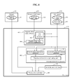
- FIG. 4 is a block diagram illustrating an example of a processor estimating a position of a mobile terminal based on a magnetic field value corrected through use of an IMU sensor, and direction information and travel distance information estimated through use of the IMU sensor.
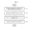
- FIG. 5 is a flowchart illustrating an example of a positioning method used by a magnetic field map-based positioning system.
- FIG. 1 illustrates an example of a mobile terminal 100 for a magnetic field map-based positioning system.
- the mobile terminal 100 includes a memory 110, a magnetic field sensor 120, an inertial measurement unit (IMU) sensor 130, and a processor 140.
- IMU inertial measurement unit
- the memory 110 stores information associated with a magnetic field map.
- the magnetic field map includes magnetic field values measured in advance at positions included in a predetermined range of a region, for example, a region for which estimation of a position of the mobile terminal 100 is to be performed.
- the positions may include positions at predetermined intervals, positions allowing a magnetic field value to be measured, and/or positions to which the mobile terminal 100 is able to reach.
- the positions may include positions in a three-dimensional (3D) space, as opposed to positions in a two-dimensional (2D) plane.
- the mobile terminal 100 may be utilized to estimate a position indoors, such as an inside of a high-rise building and other types of buildings.
- a magnetic field may be measured on each floor of the high-rise building at a fixed position, e.g., the same position when viewed in a 2D planar view.
- the fixed positions appear to be the same in the 2D planar view, the fixed positions include different altitudes in the 3D space. Accordingly, the measured magnetic field values are different from each other.
- the memory 110 may store magnetic field maps corresponding to regions. That is, the memory 110 may store the magnetic field maps to estimate a position in the regions. In this example, each floor of the high-rise building may be included in the regions.
- the magnetic field sensor 120 measures a magnetic field value at a position of the mobile terminal 100
- the IMU sensor 130 measures an acceleration value and a gyro value of the mobile terminal 100.
- the magnetic field sensor 120 may measure a magnetic field value of each of three axes including an-x axis, a-y axis, and a-z axis that correspond to the position of the mobile terminal 100.
- the IMU sensor 130 may include three accelerometers to measure acceleration values of the x-axis, the y-axis, and the z-axis, and three gyroscopes to measure gyro values of the x-axis, the y-axis, and the z-axis.
- the term "gyro values" refers to values of a rotation and an orientation measured by a gyroscope.
- the processor 140 compares the magnetic field value measured by the magnetic field sensor 120 and the magnetic field map stored in the memory 110. Based on this comparison, the processor 140 estimates, as the position of the mobile terminal 100, a point including a magnetic field value similar to or the same as the measured magnetic field value, from among points included in the magnetic field map.
- the measured magnetic field value includes a tilt error.
- the tilt error is an error included in the measured magnetic field value due to a tilt of the magnetic field sensor 120.
- the tilt error may be expressed by a degree of rotation about each of the three axes.
- the degree of rotation about each of the three axes may be expressed by a pitch, a roll, and a yaw.
- the magnetic field sensor 120 included in the mobile terminal 100 is correspondingly tilted.
- a magnetic field value of each of the x-axis, the y-axis, and the-z axis measured by the tilted magnetic field sensor 120 is different from a magnetic field value of each of the x-axis, the y-axis, and the z-axis measured by a magnetic field sensor that is not tilted.
- the magnetic field sensor 120 provides the magnetic field value including the tilt error to the processor 140, and the processor 140 estimates the position of the mobile terminal 100 based on the magnetic field value including the tilt error. Accordingly, the processor 140 may inaccurately estimate the position of the mobile terminal 100.
- the processor 140 corrects the tilt error of the magnetic field sensor 120 through use of the IMU sensor 130. That is, the processor 140 corrects the tilt error of the magnetic field sensor 120 based on the acceleration value and/or the gyro value measured by the IMU sensor 130, which will be described in detail with reference to FIG. 2 .
- the processor 140 may use, for example, a Kalman filter, a particle filter, Markov localization, and/or other types of methods, as a positioning method of estimating the position of the mobile terminal 100.
- the positioning method such as the particle filter, may inaccurately estimate the position when an error occurs in an intermediate result value to be used to estimate the position while the method is being performed.
- the positioning method such as the particle filter, may perform a subsequent cycle based on a position estimated based on a previous cycle, and may repeatedly perform the process to estimate a final position.
- a drawback of the approach described in the foregoing may occur due to the magnetic field sensor 120 being affected by an external factor.
- a magnetic substance that is absent when the magnetic field map is generated may happen to exist near the mobile terminal 100 when the magnetic field sensor 120 measures the magnetic field.
- the position of the mobile terminal 100 estimated by the processor 140 may also include an error.
- the processor 140 prevents this error from occurring, through use of the IMU sensor 130.
- the processor 140 estimates a travel direction and/or a travel distance of the mobile terminal 100, based on the acceleration value and the gyro value measured by the IMU sensor 130, the magnetic field map stored in the memory 110, and the magnetic field value measured by the magnetic field sensor 120. Accordingly, an estimated position is prevented from altered to a point that is different from the real position of the mobile terminal 100 while the positioning method, such as the particle filter, is in operation. A detailed description thereof will be provided with reference to FIG. 3 .
- FIG. 2 illustrates an example of a processor estimating a position of a mobile terminal based on a magnetic field value corrected through use of an IMU sensor.
- the mobile terminal for a magnetic field map-based positioning system includes a memory 210, a magnetic field sensor 220, an IMU sensor 230, and a processor 240, which may correspond to the memory 110, the magnetic field sensor 120, the IM sensor 130, and the processor 140, respectively, of FIG. 1 .
- the processor 240 performs a positioning method.
- the processor 240 includes a magnetic field value corrector 241 and a first position estimator 242.
- the magnetic field value corrector 241 corrects a magnetic field value 221 measured by the magnetic field sensor 220 based on an acceleration value 231 and a gyro value 232 measured by the IMU sensor 230.
- the magnetic field value corrector 241 includes a tilt error calculator 243 calculating a tilt error of the mobile terminal (e.g., of the magnetic field sensor 220) based on the acceleration value 231 and the gyro value 232.
- the magnetic field value corrector 241 further includes a magnetic field value correction implementer 244 implementing a correction of the measured magnetic field value 221 based on the calculated tilt error.
- the magnetic field sensor 220 measures the magnetic field value 221 at each of an x-axis, a y-axis, and a z-axis that correspond to the position of the mobile terminal, and magnetic field values measured at the three axes may be denoted by m x , m y , and m z , respectively.
- the IMU sensor 230 measures the acceleration value 231 and the gyro value 232 at each of the x-axis, the y-axis, and the z-axis.
- Acceleration values measured at the three axes may be denoted by ⁇ x , ⁇ y , and ⁇ z , respectively, and gyro values measured at the three axes may be denoted by ⁇ x , ⁇ y , and ⁇ z , respectively.
- the tilt error of the magnetic field sensor 220 may be expressed by a pitch ⁇ , a roll ⁇ , and a yaw ⁇ of the mobile terminal.
- the tilt error calculator 243 may calculate the pitch ⁇ and the roll ⁇ of the mobile terminal based on Equation 1 and Equation 2, respectively.
- Equations 1 and 2 g denotes standard gravity.
- the tilt error calculator 243 may calculate the yaw ⁇ of the mobile terminal, by substituting the pitch ⁇ , the roll ⁇ , and the gyro values ⁇ x , ⁇ y , and ⁇ z into a differential equation to calculate an orientation expressed by Equation 3.
- ⁇ ⁇ ⁇ ⁇ ⁇ ⁇ 1 sin ⁇ ⁇ tan ⁇ cos ⁇ ⁇ tan ⁇ 0 cos ⁇ - sin ⁇ 0 sin ⁇ ⁇ sec ⁇ cos ⁇ ⁇ sec ⁇ ⁇ ⁇ x ⁇ y ⁇ z +
- the processor 240 may set, as the yaw ⁇ of the mobile terminal, a third result value from among result values of the differential equation.
- the magnetic field value correction implementer 244 calibrates the measured magnetic field value 221 based on the calculated tilt error, to correct the measured magnetic field value 221.
- the first position estimator 242 estimates the position of the mobile terminal based on the corrected magnetic field value and a magnetic field map 211 stored in the memory 210. In more detail, the first position estimator 242 compares the corrected magnetic field value with magnetic field values included in the magnetic field map 211. Based on this comparison, the first position estimator 242 estimates, as the position of the mobile terminal, a point including a magnetic field value similar to or the same as the corrected magnetic field value, from among points included in the magnetic field map. Accordingly, a reliability of the positioning method estimating the position of the mobile terminal is improved.
- FIG. 3 illustrates an example of a processor estimating a position of a mobile terminal based on direction information and travel distance information estimated through use of an IMU sensor.
- the mobile terminal for a magnetic field map-based positioning system includes a memory 310, a magnetic field sensor 320, an IMU sensor 330, and a processor 340, which may correspond to the memory 110, the magnetic field sensor 120, the IM sensor 130, and the processor 140, respectively, of FIG. 1 .
- the processor 340 performs a positioning method.
- the processor 340 includes a first direction information generator 341, a second direction information generator 342, a direction information weight setting unit 343, a travel distance calculator 344, and a second position estimator 345.
- the first direction information generator 341 generates first direction information of the mobile terminal based on a magnetic field value 321 measured by the magnetic field sensor 320 and an acceleration value 331 measured by the IMU sensor 330.
- the first direction information generator 341 may generate the first direction information ⁇ based on Equation 4.
- ⁇ tan - 1 ⁇ Y fg cos ⁇ - Z fg sin ⁇ Y fg cos ⁇ - Y fg sin ⁇ ⁇ sin ⁇ - Z fg sin ⁇ ⁇ cos ⁇
- a pitch ⁇ and a roll ⁇ of the mobile terminal may be calculated by substituting the measured acceleration value 331 into Equations 1 2, respectively.
- X fg , Y fg , and Z fg may correspond to the magnetic field values m x , m y , and m z , which are measured at the x-axis, the y-axis, and the z-axis, respectively, e.g., of the magnetic field value 321.
- the second direction information generator 342 generates second direction information of the mobile terminal based on the acceleration value 331 and a gyro value 332 measured by the IMU sensor 330.
- the second direction information generator 342 may generate the second direction information of the mobile terminal by integrating the measured gyro value 332.
- the measured gyro value 332 represents, in terms of physics, an angular acceleration component of the mobile terminal.
- the second direction information e.g., a variance of an angle of the mobile terminal
- the second direction information generator 342 may calculate an instantaneous angular acceleration component of the mobile terminal by integrating the measured gyro value 332 once with respect to a time. The second direction information generator 342 may then multiply the calculated instantaneous angular acceleration component by the time to obtain the second direction information of the mobile terminal. In another example, the second direction information generator 342 may generate the second direction information in the same manner that the tilt error calculator 243 of FIG. 2 calculates the yaw ⁇ of the mobile terminal.
- the direction information weight setting unit 343 sets a direction information weight of the mobile terminal based on the first direction information and the second direction information.
- the direction information weight setting unit 343 sets the direction information weight to the second direction information when a value obtained by subtracting a variance of the second direction information from a variance of the first direction information is greater than a predetermined threshold value.
- the direction information weight setting unit 343 sets the direction information weight to the first direction information when a value obtained by subtracting the variance of the first direction information from the variance of the second direction information is greater than the predetermined threshold value. That is, the direction information weight setting unit 343 sets the direction information weight by weighting direction information including a smaller variance than previously-estimated first direction information or second direction information, from among the currently-estimated first direction information and the second direction information estimated based on different factors.
- the first direction information uses the magnetic field value 321, and thus, may be sensitive to interference from an external magnetic substance.
- the second direction information may integrate the measured gyro value 332, and thus, may be sensitive to a temporal component.
- the direction information weight setting unit 343 may independently calculate the first direction information and the second direction information sensitive to different external factors.
- the direction information weight setting unit 343 may then determine direction information including a smaller variance than previously-estimated direction information, from among the currently-estimated first direction information and the second direction information, as more reliable direction information.
- the direction information weight setting unit 343 may apply a weight to the reliable direction information to generate more accurate direction information.
- the external factors include the external magnetic substance for the first direction information, and the temporal component for the second direction information.
- the travel distance calculator 344 calculates a travel distance of the mobile terminal based on the measured acceleration value 331. For example travel distance calculator 344 may integrate, twice, the measured acceleration value 331 with respect to a time, to calculate the travel distance. In another example, the travel distance calculator 344 may integrate, once, the measured acceleration value 331 with respect to a time to calculate an instantaneous velocity component, and may multiply the calculated instantaneous velocity component by the time to calculate the travel distance.
- the second position estimator 345 estimates the position of the mobile terminal based on a magnetic field map 311 stored in a memory 310, the measured magnetic field value 321, the direction information weight, and the travel distance. That is, the second position estimator 345 sets a range of a region in which the mobile terminal is likely to be located based on the direction information weight and the travel distance.
- the second position estimator 345 may estimate, to be the position of the mobile terminal, a point that is completely different from a real position of the mobile terminal, according to a positioning method comparing the measured magnetic field value 321 with the magnetic field map 311.
- the second position estimator 345 may exclude an estimated position value exceeding the range of the region in which the mobile terminal is likely to be located. In this manner, the second position estimator 345 may prevent an estimated position from being altered to a wrong position due to an external interference, such as, for example, a magnetic substance.
- FIG. 4 is illustrates an example of a processor estimating a position of a mobile terminal based on a magnetic field value corrected through use of an IMU sensor, and direction information and travel distance information estimated through use of the IMU sensor.
- the mobile terminal for a magnetic field map-based positioning system includes a memory 410, a magnetic field sensor 420, an IMU sensor 430, and a processor 440, which may correspond to the memory 110, the magnetic field sensor 120, the IM sensor 130, and the processor 140, respectively, of FIG. 1 .
- the processor 440 performs a positioning method.
- the processor 440 improves a reliability of the estimated position of the mobile terminal through use of the magnetic field value of which a tilt error is corrected as described in FIG. 2 , and a direction information weight and a travel distance as described in FIG. 3 .
- the processor 440 includes a magnetic field value corrector 441, a direction information generator 442, a travel distance calculator 443, and a third position estimator 444.
- the magnetic field value corrector 441 corrects a magnetic field value 421 measured by a magnetic field sensor 420 based on an acceleration value 431 and a gyro value 432 measured by an IMU sensor 430.
- the magnetic field value corrector 441 includes a tilt error calculator 445 and a magnetic field value correction implementer 446.
- the tilt error calculator 445 calculates the tilt error of the mobile terminal based on the gyro value 432 and the acceleration value 431.
- the magnetic field value correction implementer 446 implements a correction on the measured magnetic field value 421 based on the calculated tilt error.
- the direction information generator 442 includes a first direction information generator 447, a second direction information generator 448, and a direction information weight setting unit 449.
- the first direction information generator 447 generates first direction information of the mobile terminal based on the corrected magnetic field value 421 corrected by the magnetic field value corrector 441, and the acceleration value 431.
- the second direction information generator 448 generates second direction information of the mobile terminal based on the acceleration value 431 and the gyro value 432 measured by the IMU sensor 430.
- the direction information weight setting unit 449 sets a direction information weight of the mobile terminal based on the first direction information and the second direction information.
- the travel distance calculator 443 calculates a travel distance of the mobile terminal based on the acceleration value 431.
- the third position estimator 444 estimates the position of the mobile terminal based on a magnetic field map 411 stored in a memory 410, the corrected magnetic field value 421 corrected by the magnetic field value corrector 441, the direction information weight, and the travel distance.
- FIG. 5 illustrates an example of a positioning method used by a magnetic field map-based positioning system.
- the positioning system obtains information associated with a magnetic field map corresponding to a target region of the positioning system.
- the positioning system measures a magnetic field value at a position of at least one terminal included in the target region.
- the positioning system measures an acceleration value and a gyro value of the terminal.
- the positioning system estimates the position of the terminal based on the magnetic field map, the magnetic field value, the acceleration value, and the gyro value.
- the estimating of the position of the terminal in operation 540 may include calculating a tilt error of the terminal based on the the acceleration value and the gyro value, correcting the magnetic field value based on the tilt error, and estimating the position of the terminal based on the magnetic field map and the corrected magnetic field value.
- the estimating the position of the terminal in operation 540 may include generating first direction information based on the magnetic field value and the acceleration value, generating second direction information based on the acceleration value and the gyro value, and setting a direction information weight based on the first direction information and the second direction information.
- the estimating the position of the terminal may further include calculating a travel distance of the based on the acceleration value, and estimating the position of the terminal based on the magnetic field map, the magnetic field value, the direction information weight, and the travel distance.
- the estimating of the position of the terminal in operation 540 may include correcting the magnetic field value based on the acceleration value and the gyro value, and generating direction information weight of the terminal based on the acceleration value, the gyro value, and the corrected magnetic field value.
- the estimating of the position of the terminal may further include calculating the travel distance of the terminal based on the acceleration value, and estimating the position of the terminal based on the magnetic field map, the magnetic field value, the direction information weight, and the travel distance.
- the units described herein may be implemented using hardware components and software components.
- the hardware components may include microphones, amplifiers, band-pass filters, audio to digital convertors, and processing devices.
- a processing device may be implemented using one or more general-purpose or special purpose computers, such as, for example, a processor, a controller and an arithmetic logic unit, a digital signal processor, a microcomputer, a field programmable array, a programmable logic unit, a microprocessor or any other device capable of responding to and executing instructions in a defined manner.
- the processing device may run an operating system (OS) and one or more software applications that run on the OS.
- the processing device also may access, store, manipulate, process, and create data in response to execution of the software.
- OS operating system
- a processing device may include multiple processing elements and multiple types of processing elements.
- a processing device may include multiple processors or a processor and a controller.
- different processing configurations are possible, such a parallel processors.
- the software may include a computer program, a piece of code, an instruction, or some combination thereof, to independently or collectively instruct or configure the processing device to operate as desired.
- Software and data may be embodied permanently or temporarily in any type of machine, component, physical or virtual equipment, computer storage medium or device, or in a propagated signal wave capable of providing instructions or data to or being interpreted by the processing device.
- the software also may be distributed over network coupled computer systems so that the software is stored and executed in a distributed fashion.
- the software and data may be stored by one or more computer readable recording mediums.
- the computer readable recording medium may include any data storage device that can store data which can be thereafter read by a computer system or processing device.
- non-transitory computer readable recording medium examples include read-only memory (ROM), random-access memory (RAM), CD-ROMs, magnetic tapes, floppy disks, optical data storage devices.
- ROM read-only memory
- RAM random-access memory
- CD-ROMs compact disc-read only memory
- magnetic tapes magnetic tapes
- floppy disks optical data storage devices.
- functional programs, codes, and code segments to accomplish the examples disclosed herein can be easily construed by programmers skilled in the art to which the examples pertain based on and using the flow diagrams and block diagrams of the figures and their corresponding descriptions as provided herein.
- a terminal or device described herein may refer to mobile devices such as a cellular phone, a personal digital assistant (PDA), a digital camera, a portable game console, and an MP3 player, a portable/personal multimedia player (PMP), a handheld e-book, a portable laptop PC, a global positioning system (GPS) navigation, a tablet, a sensor, and devices such as a desktop PC, a high definition television (HDTV), an optical disc player, a setup box, a home appliance, and the like that are capable of wireless communication or network communication consistent with that which is disclosed herein.
- mobile devices such as a cellular phone, a personal digital assistant (PDA), a digital camera, a portable game console, and an MP3 player, a portable/personal multimedia player (PMP), a handheld e-book, a portable laptop PC, a global positioning system (GPS) navigation, a tablet, a sensor, and devices such as a desktop PC, a high definition television (HDTV), an optical disc player, a setup box
Landscapes
- Engineering & Computer Science (AREA)
- Remote Sensing (AREA)
- Radar, Positioning & Navigation (AREA)
- Physics & Mathematics (AREA)
- General Physics & Mathematics (AREA)
- Automation & Control Theory (AREA)
- Electromagnetism (AREA)
- Life Sciences & Earth Sciences (AREA)
- Computer Networks & Wireless Communication (AREA)
- Signal Processing (AREA)
- Environmental & Geological Engineering (AREA)
- Geology (AREA)
- General Life Sciences & Earth Sciences (AREA)
- Geophysics (AREA)
- Navigation (AREA)
Abstract
Description
- The following description relates to a mobile terminal device for a positioning system based on a magnetic field map and a method thereof.
- A mobile communication signal-based positioning method may approximate a position of a terminal based on a position of a cell base station connected to the terminal and on a proximity scheme, or based on triangulation measuring a travel distance of a signal between the terminal and at least three cell base stations near the terminal. A wireless LAN-based positioning method may approximate a position of a wireless LAN terminal based on a position of an access point (AP) that the terminal belongs to, or based on a strength of a signal at an AP near the terminal to perform pattern matching through use of a fingerprint recorded in advance. An ultra-wide band (UWB)-based positioning method may approximate a position of a terminal based on triangulation measuring a distance between the terminal and an AP that generates a UWB signal.
- A magnetic field map-based positioning method may approximate a position of a terminal based on a magnetic field at the position of the terminal. In this example, representative positioning methods may include a Kalman filter, a particle filter, Markov localization, and other types of methods. The methods may measure environmental parameters varying, in several forms, as a mobile terminal moves, and may estimate a position of the mobile terminal based on the result of the measurement.
- In one general aspect, there is provided a mobile terminal for a magnetic field map-based positioning system, including a memory configured to store a magnetic field map including magnetic field values at positions. The mobile terminal further includes a magnetic field sensor configured to measure a magnetic field value at a position of the mobile terminal. The mobile terminal further includes an inertial measurement unit (IMU) sensor configured to measure an acceleration value and a gyro value of the mobile terminal. The mobile terminal further includes a processor configured to determine the position of the mobile terminal based on the magnetic field map, the magnetic field value, the acceleration value, and the gyro value.
- In a possible embodiment the gyro value includes a rotation value and an orientation value of the mobile terminal.
- In a possible embodiment the processor includes a magnetic field value corrector configured to correct the magnetic field value based on the acceleration value and the gyro value. The process further includes a first position estimator configured to determine the position of the mobile terminal based on the magnetic field map and the corrected magnetic field value.
- In a possible embodiment the magnetic field value corrector includes a tilt error calculator configured to determine a tilt error of the mobile terminal based on the acceleration value and the gyro value. The magnetic field value corrector further includes a magnetic field value correction implementer configured to correct the magnetic field value based on the tilt error.
- In a possible embodiment the tilt error includes a pitch, a roll, and a yaw of the mobile terminal.
- In a possible embodiment the processor includes a first direction information generator configured to generate first direction information based on the magnetic field value and the acceleration value. The processor further includes a second direction information generator configured to generate second direction information based on the acceleration value and the gyro value. The processor further includes a direction information weight setting unit configured to set a direction information weight based on the first direction information and the second direction information.
- In a possible embodiment the direction information weight setting unit is further configured to subtract a variance of the second direction information from a variance of the first direction information to determine a first value. The direction information weight setting unit is further configured to set the direction information weight to the second direction information if the first value is greater than a predetermined threshold value. The direction information weight setting unit is further configured to subtract the variance of the first direction information from the variance of the second direction information to determine a second value. The direction information weight setting unit is further configured to set the direction information weight to the first direction information if the second value is greater than the predetermined threshold value.
- In a possible embodiment the processor further includes a travel distance calculator configured to determine a travel distance of the mobile terminal based on the acceleration value. The processor further includes a second position estimator configured to determine the position of the mobile terminal based on the magnetic field map, the magnetic field value, the direction information weight, and the travel distance.
- In a possible embodiment the processor includes a magnetic field value corrector configured to correct the magnetic field value based on the acceleration value and the gyro value. The processor further includes a direction information generator configured to set direction information weight of the mobile terminal based on the corrected magnetic field value, the acceleration value, and the gyro value. The processor further includes a travel distance calculator configured to determine a travel distance of the mobile terminal based on the acceleration value. The processor further includes a third position estimator configured to determine the position of the mobile terminal based on the magnetic field map, the corrected magnetic field value, the direction information weight, and the travel distance.
- In a possible embodiment the processor is further configured to determine the position of the mobile terminal based on a particle filter, or a Kalman filter, or Markov localization, or any combination thereof.
- In another general aspect, there is provided a positioning method for a magnetic field map-based positioning system, including determining a magnetic field map including magnetic field values at positions. The method further includes measuring a magnetic field value at a position of a mobile terminal. The method further includes measuring an acceleration value and a gyro value of the mobile terminal. The method further includes determining the position of the mobile terminal based on the magnetic field map, the magnetic field value, the acceleration value, and the gyro value.
- In a possible embodiment the gyro value includes a rotation value and an orientation value of the mobile terminal.
- In a possible embodiment the determining of the position of the mobile terminal includes correcting the magnetic field value based on the acceleration value and the gyro value. The determining of the position of the mobile terminal further includes determining the position of the mobile terminal based on the magnetic field map and the corrected magnetic field value.
- In a possible embodiment the correcting includes determining a tilt error of the mobile terminal based on the acceleration value and the gyro value. The correcting further includes correcting the magnetic field value based on the tilt error.
- In a possible embodiment the tilt error includes a pitch, a roll, and a yaw of the mobile terminal.
- In a possible embodiment the determining of the position of the mobile terminal includes generating first direction information based on the the magnetic field value and the acceleration value. The determining of the position of the mobile terminal further includes generating second direction information based on the acceleration value and the gyro value. The determining of the position of the mobile terminal further includes setting a direction information weight based on the first direction information and the second direction information.
- In a possible embodiment the setting includes subtracting a variance of the second direction information from a variance of the first direction information to determine a first value. The setting further includes setting the direction information weight to the second direction information if the first value is greater than a predetermined threshold value. The setting further includes subtracting the variance of the first direction information from the variance of the second direction information to determine a second value. The setting further includes setting the direction information weight to the first direction information if the second value is greater than the predetermined threshold value.
- In a possible embodiment the determining of the position of the mobile terminal further includes determining a travel distance of the mobile terminal based on the acceleration value. The determining of the position of the mobile terminal further includes determining the position of the mobile terminal based on the magnetic field map, the magnetic field value, the direction information weight, and the travel distance.
- In a possible embodiment the determining of the position of the mobile terminal includes correcting the magnetic field value based on the acceleration value and the gyro value. The determining of the position of the mobile terminal further includes setting direction information weight of the mobile terminal based on the corrected magnetic field value, the acceleration value, and the gyro value. The determining of the position of the mobile terminal further includes determining a travel distance of the mobile terminal based on the acceleration value. The determining of the position of the mobile terminal further includes determining the position of the mobile terminal based on the the magnetic field map, the corrected magnetic field value, the direction information weight, and the travel distance.
- According to a further aspect, to which the present application relates, a non-transitory computer-readable storage medium stores a program including instructions to implement the method.
- Other features and aspects may be apparent from the following detailed description, the drawings, and the claims.
-
FIG. 1 is a block diagram illustrating an example of a mobile terminal for a magnetic field map-based positioning system. -
FIG. 2 is a block diagram illustrating an example of a processor estimating a position of a mobile terminal based on a magnetic field value corrected through use of an inertial measurement unit (IMU) sensor. -
FIG. 3 is a block diagram illustrating an example of a processor estimating a position of a mobile terminal based on direction information and travel distance information estimated through use of an IMU sensor. -
FIG. 4 is a block diagram illustrating an example of a processor estimating a position of a mobile terminal based on a magnetic field value corrected through use of an IMU sensor, and direction information and travel distance information estimated through use of the IMU sensor. -
FIG. 5 is a flowchart illustrating an example of a positioning method used by a magnetic field map-based positioning system. - Throughout the drawings and the detailed description, unless otherwise described, the same drawing reference numerals will be understood to refer to the same elements, features, and structures. The relative size and depiction of these elements may be exaggerated for clarity, illustration, and convenience.
- The following detailed description is provided to assist the reader in gaining a comprehensive understanding of the methods, apparatuses and/or systems described herein. Accordingly, various changes, modifications, and equivalents of the systems, apparatuses and/or methods described herein will be self-evident to those of ordinary skill in the art. The progression of processing steps and/or operations described is an example; however, the sequence of and/or operations is not limited to that set forth herein and may be changed as is known in the art, with the exception of steps and/or operations necessarily occurring in a certain order. Also, descriptions of well-known functions and constructions may be omitted for increased clarity and conciseness.
-
FIG. 1 illustrates an example of amobile terminal 100 for a magnetic field map-based positioning system. Themobile terminal 100 includes amemory 110, amagnetic field sensor 120, an inertial measurement unit (IMU)sensor 130, and aprocessor 140. - The
memory 110 stores information associated with a magnetic field map. The magnetic field map includes magnetic field values measured in advance at positions included in a predetermined range of a region, for example, a region for which estimation of a position of themobile terminal 100 is to be performed. - In this example, the positions may include positions at predetermined intervals, positions allowing a magnetic field value to be measured, and/or positions to which the
mobile terminal 100 is able to reach. In addition, the positions may include positions in a three-dimensional (3D) space, as opposed to positions in a two-dimensional (2D) plane. For example, themobile terminal 100 may be utilized to estimate a position indoors, such as an inside of a high-rise building and other types of buildings. A magnetic field may be measured on each floor of the high-rise building at a fixed position, e.g., the same position when viewed in a 2D planar view. Although the fixed positions appear to be the same in the 2D planar view, the fixed positions include different altitudes in the 3D space. Accordingly, the measured magnetic field values are different from each other. - In addition, the
memory 110 may store magnetic field maps corresponding to regions. That is, thememory 110 may store the magnetic field maps to estimate a position in the regions. In this example, each floor of the high-rise building may be included in the regions. - The
magnetic field sensor 120 measures a magnetic field value at a position of themobile terminal 100, and theIMU sensor 130 measures an acceleration value and a gyro value of themobile terminal 100. In this example, themagnetic field sensor 120 may measure a magnetic field value of each of three axes including an-x axis, a-y axis, and a-z axis that correspond to the position of themobile terminal 100. TheIMU sensor 130 may include three accelerometers to measure acceleration values of the x-axis, the y-axis, and the z-axis, and three gyroscopes to measure gyro values of the x-axis, the y-axis, and the z-axis. As used in herein, the term "gyro values" refers to values of a rotation and an orientation measured by a gyroscope. - The
processor 140 compares the magnetic field value measured by themagnetic field sensor 120 and the magnetic field map stored in thememory 110. Based on this comparison, theprocessor 140 estimates, as the position of themobile terminal 100, a point including a magnetic field value similar to or the same as the measured magnetic field value, from among points included in the magnetic field map. - When the
mobile terminal 100 is tilted while themagnetic field sensor 120 measures the magnetic field value at the position of themobile terminal 100, the measured magnetic field value includes a tilt error. The tilt error is an error included in the measured magnetic field value due to a tilt of themagnetic field sensor 120. In this example, the tilt error may be expressed by a degree of rotation about each of the three axes. The degree of rotation about each of the three axes may be expressed by a pitch, a roll, and a yaw. - As the
mobile terminal 100 is tilted, themagnetic field sensor 120 included in themobile terminal 100 is correspondingly tilted. In this example, a magnetic field value of each of the x-axis, the y-axis, and the-z axis measured by the tiltedmagnetic field sensor 120 is different from a magnetic field value of each of the x-axis, the y-axis, and the z-axis measured by a magnetic field sensor that is not tilted. Themagnetic field sensor 120 provides the magnetic field value including the tilt error to theprocessor 140, and theprocessor 140 estimates the position of themobile terminal 100 based on the magnetic field value including the tilt error. Accordingly, theprocessor 140 may inaccurately estimate the position of themobile terminal 100. - The
processor 140 corrects the tilt error of themagnetic field sensor 120 through use of theIMU sensor 130. That is, theprocessor 140 corrects the tilt error of themagnetic field sensor 120 based on the acceleration value and/or the gyro value measured by theIMU sensor 130, which will be described in detail with reference toFIG. 2 . - In further examples, the
processor 140 may use, for example, a Kalman filter, a particle filter, Markov localization, and/or other types of methods, as a positioning method of estimating the position of themobile terminal 100. The positioning method, such as the particle filter, may inaccurately estimate the position when an error occurs in an intermediate result value to be used to estimate the position while the method is being performed. The positioning method, such as the particle filter, may perform a subsequent cycle based on a position estimated based on a previous cycle, and may repeatedly perform the process to estimate a final position. - For example, a drawback of the approach described in the foregoing may occur due to the
magnetic field sensor 120 being affected by an external factor. In this example, a magnetic substance that is absent when the magnetic field map is generated may happen to exist near themobile terminal 100 when themagnetic field sensor 120 measures the magnetic field. - When the magnetic field value measured by the
magnetic field sensor 120 is interrupted by an external factor while the position of themobile terminal 100 is being estimated, there may be an error in the intermediate result value to be used to estimate the position. Accordingly, the position of themobile terminal 100 estimated by theprocessor 140 may also include an error. - The
processor 140 prevents this error from occurring, through use of theIMU sensor 130. Theprocessor 140 estimates a travel direction and/or a travel distance of themobile terminal 100, based on the acceleration value and the gyro value measured by theIMU sensor 130, the magnetic field map stored in thememory 110, and the magnetic field value measured by themagnetic field sensor 120. Accordingly, an estimated position is prevented from altered to a point that is different from the real position of themobile terminal 100 while the positioning method, such as the particle filter, is in operation. A detailed description thereof will be provided with reference toFIG. 3 . -
FIG. 2 illustrates an example of a processor estimating a position of a mobile terminal based on a magnetic field value corrected through use of an IMU sensor. The mobile terminal for a magnetic field map-based positioning system includes amemory 210, amagnetic field sensor 220, anIMU sensor 230, and aprocessor 240, which may correspond to thememory 110, themagnetic field sensor 120, theIM sensor 130, and theprocessor 140, respectively, ofFIG. 1 . Theprocessor 240 performs a positioning method. - In more detail, the
processor 240 includes a magneticfield value corrector 241 and afirst position estimator 242. The magneticfield value corrector 241 corrects amagnetic field value 221 measured by themagnetic field sensor 220 based on anacceleration value 231 and agyro value 232 measured by theIMU sensor 230. The magneticfield value corrector 241 includes atilt error calculator 243 calculating a tilt error of the mobile terminal (e.g., of the magnetic field sensor 220) based on theacceleration value 231 and thegyro value 232. The magneticfield value corrector 241 further includes a magnetic fieldvalue correction implementer 244 implementing a correction of the measuredmagnetic field value 221 based on the calculated tilt error. - For example, the
magnetic field sensor 220 measures themagnetic field value 221 at each of an x-axis, a y-axis, and a z-axis that correspond to the position of the mobile terminal, and magnetic field values measured at the three axes may be denoted by mx, my, and mz, respectively. TheIMU sensor 230 measures theacceleration value 231 and thegyro value 232 at each of the x-axis, the y-axis, and the z-axis. Acceleration values measured at the three axes may be denoted by α x , α y , and α z , respectively, and gyro values measured at the three axes may be denoted by ω x, ω y, and ω z , respectively. - In this example, the tilt error of the
magnetic field sensor 220 may be expressed by a pitch θ, a roll ϕ, and a yaw ψ of the mobile terminal. Thetilt error calculator 243 may calculate the pitch θ and the roll ϕ of the mobile terminal based on Equation 1 and Equation 2, respectively.

- In Equations 1 and 2, g denotes standard gravity.
- In addition, the
tilt error calculator 243 may calculate the yaw ψ of the mobile terminal, by substituting the pitch θ, the roll ϕ, and the gyro values ω x, ω y, and ω z into a differential equation to calculate an orientation expressed by Equation 3.
- In Equation 3, the
processor 240 may set, as the yaw ψ of the mobile terminal, a third result value from among result values of the differential equation. - The magnetic field
value correction implementer 244 calibrates the measuredmagnetic field value 221 based on the calculated tilt error, to correct the measuredmagnetic field value 221. - The
first position estimator 242 estimates the position of the mobile terminal based on the corrected magnetic field value and amagnetic field map 211 stored in thememory 210. In more detail, thefirst position estimator 242 compares the corrected magnetic field value with magnetic field values included in themagnetic field map 211. Based on this comparison, thefirst position estimator 242 estimates, as the position of the mobile terminal, a point including a magnetic field value similar to or the same as the corrected magnetic field value, from among points included in the magnetic field map. Accordingly, a reliability of the positioning method estimating the position of the mobile terminal is improved. -
FIG. 3 illustrates an example of a processor estimating a position of a mobile terminal based on direction information and travel distance information estimated through use of an IMU sensor. The mobile terminal for a magnetic field map-based positioning system includes amemory 310, amagnetic field sensor 320, anIMU sensor 330, and aprocessor 340, which may correspond to thememory 110, themagnetic field sensor 120, theIM sensor 130, and theprocessor 140, respectively, ofFIG. 1 . Theprocessor 340 performs a positioning method. - In more detail, the
processor 340 includes a firstdirection information generator 341, a seconddirection information generator 342, a direction informationweight setting unit 343, atravel distance calculator 344, and asecond position estimator 345. The firstdirection information generator 341 generates first direction information of the mobile terminal based on amagnetic field value 321 measured by themagnetic field sensor 320 and anacceleration value 331 measured by theIMU sensor 330. - For example, the first
direction information generator 341 may generate the first direction information ψ based on Equation 4.
- In Equation 4, a pitch θ and a roll ϕ of the mobile terminal may be calculated by substituting the measured
acceleration value 331 into Equations 1 2, respectively. Xfg, Yfg, and Zfg may correspond to the magnetic field values mx, my, and mz, which are measured at the x-axis, the y-axis, and the z-axis, respectively, e.g., of themagnetic field value 321. - The second
direction information generator 342 generates second direction information of the mobile terminal based on theacceleration value 331 and agyro value 332 measured by theIMU sensor 330. For example, the seconddirection information generator 342 may generate the second direction information of the mobile terminal by integrating the measuredgyro value 332. The measuredgyro value 332 represents, in terms of physics, an angular acceleration component of the mobile terminal. Thus, it is apparent to one skilled in the art that the second direction information (e.g., a variance of an angle of the mobile terminal) may be obtained by integrating the measuredgyro value 332 two times with respect to a time. In another example, the seconddirection information generator 342 may calculate an instantaneous angular acceleration component of the mobile terminal by integrating the measuredgyro value 332 once with respect to a time. The seconddirection information generator 342 may then multiply the calculated instantaneous angular acceleration component by the time to obtain the second direction information of the mobile terminal. In another example, the seconddirection information generator 342 may generate the second direction information in the same manner that thetilt error calculator 243 ofFIG. 2 calculates the yaw ψ of the mobile terminal. - The direction information
weight setting unit 343 sets a direction information weight of the mobile terminal based on the first direction information and the second direction information. The direction informationweight setting unit 343 sets the direction information weight to the second direction information when a value obtained by subtracting a variance of the second direction information from a variance of the first direction information is greater than a predetermined threshold value. The direction informationweight setting unit 343 sets the direction information weight to the first direction information when a value obtained by subtracting the variance of the first direction information from the variance of the second direction information is greater than the predetermined threshold value. That is, the direction informationweight setting unit 343 sets the direction information weight by weighting direction information including a smaller variance than previously-estimated first direction information or second direction information, from among the currently-estimated first direction information and the second direction information estimated based on different factors. - For example, the first direction information uses the
magnetic field value 321, and thus, may be sensitive to interference from an external magnetic substance. The second direction information may integrate the measuredgyro value 332, and thus, may be sensitive to a temporal component. Accordingly, the direction informationweight setting unit 343 may independently calculate the first direction information and the second direction information sensitive to different external factors. The direction informationweight setting unit 343 may then determine direction information including a smaller variance than previously-estimated direction information, from among the currently-estimated first direction information and the second direction information, as more reliable direction information. The direction informationweight setting unit 343 may apply a weight to the reliable direction information to generate more accurate direction information. In this example, the external factors include the external magnetic substance for the first direction information, and the temporal component for the second direction information. - The
travel distance calculator 344 calculates a travel distance of the mobile terminal based on the measuredacceleration value 331. For exampletravel distance calculator 344 may integrate, twice, the measuredacceleration value 331 with respect to a time, to calculate the travel distance. In another example, thetravel distance calculator 344 may integrate, once, the measuredacceleration value 331 with respect to a time to calculate an instantaneous velocity component, and may multiply the calculated instantaneous velocity component by the time to calculate the travel distance. - The
second position estimator 345 estimates the position of the mobile terminal based on amagnetic field map 311 stored in amemory 310, the measuredmagnetic field value 321, the direction information weight, and the travel distance. That is, thesecond position estimator 345 sets a range of a region in which the mobile terminal is likely to be located based on the direction information weight and the travel distance. - For example, if the measured
magnetic field value 321 is affected by an external magnetic substance, thesecond position estimator 345 may estimate, to be the position of the mobile terminal, a point that is completely different from a real position of the mobile terminal, according to a positioning method comparing the measuredmagnetic field value 321 with themagnetic field map 311. In this example, thesecond position estimator 345 may exclude an estimated position value exceeding the range of the region in which the mobile terminal is likely to be located. In this manner, thesecond position estimator 345 may prevent an estimated position from being altered to a wrong position due to an external interference, such as, for example, a magnetic substance. -
FIG. 4 is illustrates an example of a processor estimating a position of a mobile terminal based on a magnetic field value corrected through use of an IMU sensor, and direction information and travel distance information estimated through use of the IMU sensor. The mobile terminal for a magnetic field map-based positioning system includes amemory 410, amagnetic field sensor 420, anIMU sensor 430, and aprocessor 440, which may correspond to thememory 110, themagnetic field sensor 120, theIM sensor 130, and theprocessor 140, respectively, ofFIG. 1 . Theprocessor 440 performs a positioning method. Theprocessor 440 improves a reliability of the estimated position of the mobile terminal through use of the magnetic field value of which a tilt error is corrected as described inFIG. 2 , and a direction information weight and a travel distance as described inFIG. 3 . - In more detail, the
processor 440 includes a magneticfield value corrector 441, adirection information generator 442, atravel distance calculator 443, and athird position estimator 444. The magneticfield value corrector 441 corrects amagnetic field value 421 measured by amagnetic field sensor 420 based on anacceleration value 431 and agyro value 432 measured by anIMU sensor 430. - The magnetic
field value corrector 441 includes atilt error calculator 445 and a magnetic fieldvalue correction implementer 446. Thetilt error calculator 445 calculates the tilt error of the mobile terminal based on thegyro value 432 and theacceleration value 431. The magnetic fieldvalue correction implementer 446 implements a correction on the measuredmagnetic field value 421 based on the calculated tilt error. - The
direction information generator 442 includes a firstdirection information generator 447, a seconddirection information generator 448, and a direction informationweight setting unit 449. The firstdirection information generator 447 generates first direction information of the mobile terminal based on the correctedmagnetic field value 421 corrected by the magneticfield value corrector 441, and theacceleration value 431. The seconddirection information generator 448 generates second direction information of the mobile terminal based on theacceleration value 431 and thegyro value 432 measured by theIMU sensor 430. The direction informationweight setting unit 449 sets a direction information weight of the mobile terminal based on the first direction information and the second direction information. - The
travel distance calculator 443 calculates a travel distance of the mobile terminal based on theacceleration value 431. Thethird position estimator 444 estimates the position of the mobile terminal based on amagnetic field map 411 stored in amemory 410, the correctedmagnetic field value 421 corrected by the magneticfield value corrector 441, the direction information weight, and the travel distance. The examples described in the foregoing with reference toFIGS. 1 through 3 may be applicable to the elements ofFIG. 4 , and thus, detailed descriptions thereof will be omitted. -
FIG. 5 illustrates an example of a positioning method used by a magnetic field map-based positioning system. Inoperation 510, the positioning system obtains information associated with a magnetic field map corresponding to a target region of the positioning system. Inoperation 520, the positioning system measures a magnetic field value at a position of at least one terminal included in the target region. Inoperation 530, the positioning system measures an acceleration value and a gyro value of the terminal. Inoperation 540, the positioning system estimates the position of the terminal based on the magnetic field map, the magnetic field value, the acceleration value, and the gyro value. - For example, the estimating of the position of the terminal in
operation 540 may include calculating a tilt error of the terminal based on the the acceleration value and the gyro value, correcting the magnetic field value based on the tilt error, and estimating the position of the terminal based on the magnetic field map and the corrected magnetic field value. In another example, the estimating the position of the terminal inoperation 540 may include generating first direction information based on the magnetic field value and the acceleration value, generating second direction information based on the acceleration value and the gyro value, and setting a direction information weight based on the first direction information and the second direction information. In this example, the estimating the position of the terminal may further include calculating a travel distance of the based on the acceleration value, and estimating the position of the terminal based on the magnetic field map, the magnetic field value, the direction information weight, and the travel distance. - In still another example, the estimating of the position of the terminal in
operation 540 may include correcting the magnetic field value based on the acceleration value and the gyro value, and generating direction information weight of the terminal based on the acceleration value, the gyro value, and the corrected magnetic field value. In this example, the estimating of the position of the terminal may further include calculating the travel distance of the terminal based on the acceleration value, and estimating the position of the terminal based on the magnetic field map, the magnetic field value, the direction information weight, and the travel distance. The examples described in the foregoing with reference toFIGS. 1 through 4 may be applicable to modules ofFIG. 5 , and thus, detailed descriptions thereof will be omitted. - The units described herein may be implemented using hardware components and software components. For example, the hardware components may include microphones, amplifiers, band-pass filters, audio to digital convertors, and processing devices. A processing device may be implemented using one or more general-purpose or special purpose computers, such as, for example, a processor, a controller and an arithmetic logic unit, a digital signal processor, a microcomputer, a field programmable array, a programmable logic unit, a microprocessor or any other device capable of responding to and executing instructions in a defined manner. The processing device may run an operating system (OS) and one or more software applications that run on the OS. The processing device also may access, store, manipulate, process, and create data in response to execution of the software. For purpose of simplicity, the description of a processing device is used as singular; however, one skilled in the art will appreciated that a processing device may include multiple processing elements and multiple types of processing elements. For example, a processing device may include multiple processors or a processor and a controller. In addition, different processing configurations are possible, such a parallel processors.
- The software may include a computer program, a piece of code, an instruction, or some combination thereof, to independently or collectively instruct or configure the processing device to operate as desired. Software and data may be embodied permanently or temporarily in any type of machine, component, physical or virtual equipment, computer storage medium or device, or in a propagated signal wave capable of providing instructions or data to or being interpreted by the processing device. The software also may be distributed over network coupled computer systems so that the software is stored and executed in a distributed fashion. For example, the software and data may be stored by one or more computer readable recording mediums. The computer readable recording medium may include any data storage device that can store data which can be thereafter read by a computer system or processing device. Examples of the non-transitory computer readable recording medium include read-only memory (ROM), random-access memory (RAM), CD-ROMs, magnetic tapes, floppy disks, optical data storage devices. Also, functional programs, codes, and code segments to accomplish the examples disclosed herein can be easily construed by programmers skilled in the art to which the examples pertain based on and using the flow diagrams and block diagrams of the figures and their corresponding descriptions as provided herein.
- As a non-exhaustive illustration only, a terminal or device described herein may refer to mobile devices such as a cellular phone, a personal digital assistant (PDA), a digital camera, a portable game console, and an MP3 player, a portable/personal multimedia player (PMP), a handheld e-book, a portable laptop PC, a global positioning system (GPS) navigation, a tablet, a sensor, and devices such as a desktop PC, a high definition television (HDTV), an optical disc player, a setup box, a home appliance, and the like that are capable of wireless communication or network communication consistent with that which is disclosed herein.
- A number of example embodiments have been described above. Nevertheless, it will be understood that various modifications may be made. For example, suitable results may be achieved if the described techniques are performed in a different order and/or if components in a described system, architecture, device, or circuit are combined in a different manner and/or replaced or supplemented by other components or their equivalents. Accordingly, other implementations are within the scope of the following claims.
Claims (15)
- A mobile terminal for a magnetic field map-based positioning system, comprising:a memory configured to store a magnetic field map comprising magnetic field values at positions;a magnetic field sensor configured to measure a magnetic field value at a position of the mobile terminal;an inertial measurement unit (IMU) sensor configured to measure an acceleration value and a gyro value of the mobile terminal; anda processor configured to determine the position of the mobile terminal based on the magnetic field map, the magnetic field value, the acceleration value, and the gyro value.
- The mobile terminal of claim 1, wherein the gyro value comprises a rotation value and an orientation value of the mobile terminal.
- The mobile terminal of claim 1 or 2, wherein the processor comprises:a magnetic field value corrector configured to correct the magnetic field value based on the acceleration value and the gyro value; anda first position estimator configured to determine the position of the mobile terminal based on the magnetic field map and the corrected magnetic field value.
- The mobile terminal of claim 3, wherein the magnetic field value corrector comprises:a tilt error calculator configured to determine a tilt error of the mobile terminal based on the acceleration value and the gyro value; anda magnetic field value correction implementer configured to correct the magnetic field value based on the tilt error.
- The mobile terminal of claim 4, wherein the tilt error comprises a pitch, a roll, and a yaw of the mobile terminal.
- The mobile terminal of any of the preceding claims, wherein the processor comprises:a first direction information generator configured to generate first direction information based on the magnetic field value and the acceleration value;a second direction information generator configured to generate second direction information based on the acceleration value and the gyro value; anda direction information weight setting unit configured to set a direction information weight based on the first direction information and the second direction information.
- The mobile terminal of claim 6, wherein the direction information weight setting unit is further configured to:subtract a variance of the second direction information from a variance of the first direction information to determine a first value;set the direction information weight to the second direction information if the first value is greater than a predetermined threshold value;subtract the variance of the first direction information from the variance of the second direction information to determine a second value; andset the direction information weight to the first direction information if the second value is greater than the predetermined threshold value.
- The mobile terminal of claim 6 or 7, wherein the processor further comprises:a travel distance calculator configured to determine a travel distance of the mobile terminal based on the acceleration value; anda second position estimator configured to determine the position of the mobile terminal based on the magnetic field map, the magnetic field value, the direction information weight, and the travel distance.
- The mobile terminal of any of the preceding claims, wherein the processor comprises:a magnetic field value corrector configured to correct the magnetic field value based on the acceleration value and the gyro value;a direction information generator configured to set direction information weight of the mobile terminal based on the corrected magnetic field value, the acceleration value, and the gyro value;a travel distance calculator configured to determine a travel distance of the mobile terminal based on the acceleration value; anda third position estimator configured to determine the position of the mobile terminal based on the magnetic field map, the corrected magnetic field value, the direction information weight, and the travel distance.
- The mobile terminal of any of the preceding claims, wherein the processor is further configured to determine the position of the mobile terminal based on a particle filter, or a Kalman filter, or Markov localization, or any combination thereof.
- A positioning method for a magnetic field map-based positioning system, comprising:determining a magnetic field map comprising magnetic field values at positions;measuring a magnetic field value at a position of a mobile terminal;measuring an acceleration value and a gyro value of the mobile terminal; anddetermining the position of the mobile terminal based on the magnetic field map, the magnetic field value, the acceleration value, and the gyro value.
- The method of claim 11, wherein the gyro value comprises a rotation value and an orientation value of the mobile terminal.
- The method of claim 11 or 12, wherein the determining of the position of the mobile terminal comprises:correcting the magnetic field value based on the acceleration value and the gyro value; anddetermining the position of the mobile terminal based on the magnetic field map and the corrected magnetic field value.
- The method of claim 13, wherein the correcting comprises:determining a tilt error of the mobile terminal based on the acceleration value and the gyro value; andcorrecting the magnetic field value based on the tilt error.
- A non-transitory computer-readable storage medium storing a program comprising instructions to implement the method of at least claim 11 of the preceding method claims.
Applications Claiming Priority (1)
| Application Number | Priority Date | Filing Date | Title |
|---|---|---|---|
| KR1020110130398A KR101833217B1 (en) | 2011-12-07 | 2011-12-07 | Mobile terminal device for positioning system based on magnetic map and positioning method using the device |
Publications (2)
| Publication Number | Publication Date |
|---|---|
| EP2602590A1 true EP2602590A1 (en) | 2013-06-12 |
| EP2602590B1 EP2602590B1 (en) | 2017-04-19 |
Family
ID=47355811
Family Applications (1)
| Application Number | Title | Priority Date | Filing Date |
|---|---|---|---|
| EP12191402.2A Not-in-force EP2602590B1 (en) | 2011-12-07 | 2012-11-06 | Mobile terminal device for positioning system based on magnetic field map and method thereof |
Country Status (5)
| Country | Link |
|---|---|
| US (2) | US9167440B2 (en) |
| EP (1) | EP2602590B1 (en) |
| JP (1) | JP6285628B2 (en) |
| KR (1) | KR101833217B1 (en) |
| CN (2) | CN107084717B (en) |
Cited By (7)
| Publication number | Priority date | Publication date | Assignee | Title |
|---|---|---|---|---|
| DE102015205097A1 (en) * | 2015-01-15 | 2016-07-21 | Fraunhofer-Gesellschaft zur Förderung der angewandten Forschung e.V. | Location device and method for localization |
| WO2017053202A1 (en) * | 2015-09-24 | 2017-03-30 | Microsoft Technology Licensing, Llc | Magnetometer arrays for inertial navigation, mapping, and drift compensation |
| EP3339891A4 (en) * | 2015-08-25 | 2018-09-19 | Samsung Electronics Co., Ltd. | Method and apparatus for estimating position in wireless communication system |
| CN110081888A (en) * | 2019-05-15 | 2019-08-02 | 华南师范大学 | A kind of indoor positioning algorithms of inertial navigation and earth magnetism fusion based on confidence level |
| US10782135B2 (en) | 2016-04-11 | 2020-09-22 | The Regents Of The University Of Michigan | Magnetic beacon and inertial sensor localization technology |
| US11466989B2 (en) * | 2019-11-08 | 2022-10-11 | Industry Academy Cooperation Foundation Of Sejong University | Techniques for indoor positioning |
| WO2025029431A1 (en) * | 2023-08-01 | 2025-02-06 | SB Technology, Inc. | Geophysical field sensing based navigation |
Families Citing this family (77)
| Publication number | Priority date | Publication date | Assignee | Title |
|---|---|---|---|---|
| KR101957748B1 (en) | 2012-12-13 | 2019-03-13 | 삼성전자주식회사 | Method for estimating location of user terminal using difference of the true north and the magnetic north and the user terminal thereof |
| US9326103B2 (en) * | 2013-07-12 | 2016-04-26 | Microsoft Technology Licensing, Llc | Indoor location-finding using magnetic field anomalies |
| CN103363988B (en) * | 2013-07-24 | 2016-02-03 | 武汉诚迈科技有限公司 | A kind of method utilizing intelligent mobile phone sensor to realize the navigation of earth magnetism indoor positioning |
| US20150106373A1 (en) * | 2013-10-15 | 2015-04-16 | Indooratlas Oy | Generating search database based on earth's magnetic field measurements |
| KR102158029B1 (en) * | 2014-01-03 | 2020-09-21 | 한국전자통신연구원 | Method and apparatus for recognizing indoor location using field intensity map |
| KR102033334B1 (en) * | 2014-02-03 | 2019-10-17 | 한국전자통신연구원 | Wrist wearable apparatus with transformable material |
| CN103925923B (en) * | 2014-05-07 | 2017-06-16 | 南京大学 | A kind of earth magnetism indoor locating system based on adaptive particle filter device algorithm |
| CN103983266A (en) * | 2014-05-28 | 2014-08-13 | 北京天地方元科技有限公司 | Indoor locating method based on geomagnetic information and indoor locating system based on geomagnetic information |
| CN104019813B (en) * | 2014-06-19 | 2017-01-25 | 无锡知谷网络科技有限公司 | Method and system of target immediate location and map establishing |
| CN104215238A (en) * | 2014-08-21 | 2014-12-17 | 北京空间飞行器总体设计部 | Indoor positioning method of intelligent mobile phone |
| KR102230583B1 (en) * | 2014-09-19 | 2021-03-23 | 삼성전자주식회사 | Method for providing location based service, electronic apparatus, server and storage medium |
| KR101634126B1 (en) * | 2014-09-23 | 2016-06-29 | 주식회사 아이티원 | method, apparatus, and recording medium for estimating location |
| US20180003507A1 (en) * | 2014-10-27 | 2018-01-04 | Sensewhere Limited | Position estimation |
| CN104390643B (en) * | 2014-11-24 | 2017-05-31 | 上海赛特斯信息科技股份有限公司 | The method that indoor positioning is realized based on Multi-information acquisition |
| KR101581632B1 (en) * | 2015-03-10 | 2015-12-30 | 최승욱 | Method for determining contact between terminals, computer program and application therefor |
| CN106153042A (en) * | 2015-03-31 | 2016-11-23 | 日本电气株式会社 | Course angle acquisition methods and device |
| US9918203B2 (en) * | 2015-06-05 | 2018-03-13 | Apple Inc. | Correcting in-venue location estimation using structural information |
| CN104977006A (en) * | 2015-08-11 | 2015-10-14 | 北京纳尔信通科技有限公司 | Indoor positioning method based on fuzzy theory and multi-sensor fusion |
| JP2017049168A (en) * | 2015-09-03 | 2017-03-09 | 住友電気工業株式会社 | Location estimation device, location estimation system, location estimation method and location estimation program |
| US20170110016A1 (en) * | 2015-10-16 | 2017-04-20 | Droneventory Corporation | Indoor Autonomous Navigation System |
| CN105371843B (en) * | 2015-11-11 | 2018-08-24 | 浙江大学 | A kind of long-range navigation method and device based on earth's magnetic field space angle |
| US9958274B2 (en) * | 2015-12-29 | 2018-05-01 | Fujitsu Limited | Magnetic field based location determination |
| KR102153932B1 (en) * | 2016-01-12 | 2020-09-10 | 한국전자통신연구원 | Apparatus for updating of positioning infrastructure database automatically and method using the same |
| KR101947442B1 (en) * | 2016-01-12 | 2019-02-13 | 한국전자통신연구원 | Apparatus for estimating location using combination of different positioning resources and method using the same |
| CN105698792A (en) * | 2016-01-26 | 2016-06-22 | 上海实汇机电科技有限公司 | Dynamic MEMS (micro-electromechanical systems) inertial attitude measuring system based on self-adaptive robust integration algorithm |
| KR102562559B1 (en) * | 2016-01-29 | 2023-08-03 | 삼성전자주식회사 | Electronic Device and And Control Method Thereof |
| US10184964B2 (en) | 2016-03-21 | 2019-01-22 | International Business Machines Corporation | Automatic measurement and notification of electrical level using smartphone sensors |
| CN107063237A (en) * | 2016-12-14 | 2017-08-18 | 歌尔股份有限公司 | A kind of method and apparatus for measuring gestures of object angle |
| CN106885566B (en) * | 2017-01-03 | 2019-12-17 | 浙江大学 | A wearable motion sensor and its anti-magnetic field interference method |
| KR101914922B1 (en) | 2017-04-10 | 2018-11-05 | 한국정보공학 주식회사 | Method and apparatus for estimating a position |
| US10794986B2 (en) | 2017-06-02 | 2020-10-06 | Apple Inc. | Extending a radio map |
| US10477609B2 (en) | 2017-06-02 | 2019-11-12 | Apple Inc. | Healing a radio map |
| US10979854B2 (en) | 2017-06-02 | 2021-04-13 | Apple Inc. | Extending a radio map |
| US11366184B2 (en) * | 2017-06-13 | 2022-06-21 | Sony Semiconductor Solutions Corporation | Position determination device and method |
| CN107289941B (en) * | 2017-06-14 | 2021-01-08 | 湖南格纳微信息科技有限公司 | Inertial navigation-based indoor positioning method and device |
| US11473911B2 (en) | 2017-10-26 | 2022-10-18 | Sony Semiconductor Solutions Corporation | Heading determination device and method, rendering device and method |
| WO2019081754A2 (en) * | 2017-10-26 | 2019-05-02 | Sony Semiconductor Solutions Corporation | Orientation determination device and method, rendering device and method |
| US10070270B1 (en) | 2017-11-30 | 2018-09-04 | Mapsted Corp. | Mobile device localization based on spatial derivative magnetic fingerprint |
| US10257658B1 (en) * | 2017-11-30 | 2019-04-09 | Mapsted Corp. | Self-learning localization data repository |
| CN108151765B (en) * | 2017-12-27 | 2020-05-08 | 中国电子科技集团公司第五十四研究所 | Positioning and attitude measuring method for online real-time estimation and compensation of magnetometer error |
| CN108076511A (en) * | 2017-12-28 | 2018-05-25 | 浙江大学 | A kind of indoor wireless positioner and method based on low-frequency AC magnetic fields |
| US10165407B1 (en) | 2018-01-04 | 2018-12-25 | Mapsted Corp. | Magnetic landmark method and system for detecting in-building (local venue) threshold |
| US20190373413A1 (en) | 2018-06-01 | 2019-12-05 | Apple Inc. | Feature-based slam with z-axis location |
| US10352708B1 (en) | 2018-07-09 | 2019-07-16 | Mapsted Corp. | Method and system for mobile device localization using barometric fingerprint |
| US10365111B1 (en) | 2018-07-09 | 2019-07-30 | Mapsted Corp. | Method and system for crowd- sourced barometric fingerprint data repository |
| CN109557484B (en) * | 2018-11-14 | 2021-07-20 | 深圳增强现实技术有限公司 | Magnetic field detection method and system and terminal |
| KR101997411B1 (en) * | 2018-12-21 | 2019-07-05 | 세종대학교산학협력단 | Method and device for estimating location of pedestrian based on mutiple sensors |
| CN109731323B (en) * | 2018-12-29 | 2021-12-31 | 广州明朝互动科技股份有限公司 | Game system based on real-time user position |
| US10820149B2 (en) | 2019-01-25 | 2020-10-27 | Mapsted Corp. | Method and system for mobile device dual stream localization in a magnetic distortion region |
| US10816343B2 (en) | 2019-01-25 | 2020-10-27 | Mapsted Corp. | Method and system for deploying crowd-sourced magnetic distortion rejection map |
| US10634505B1 (en) | 2019-02-07 | 2020-04-28 | Mapsted Corp. | Method and system for threshold-based detection of distortive magnetic fields in indoor locations |
| US10539644B1 (en) * | 2019-02-27 | 2020-01-21 | Northern Digital Inc. | Tracking an object in an electromagnetic field |
| CN110146845B (en) * | 2019-04-17 | 2021-07-27 | 杭州电子科技大学 | An event-driven fixed-time electromagnetic source localization method |
| CN110146073A (en) * | 2019-06-11 | 2019-08-20 | 中国神华能源股份有限公司 | Personnel positioning method and apparatus based on earth magnetism |
| CN112153604B (en) * | 2019-06-28 | 2022-03-18 | 比亚迪股份有限公司 | Positioning accuracy verification method, device, storage medium, train and electronic equipment |
| US11428533B2 (en) | 2019-07-04 | 2022-08-30 | Mapsted Corp. | Generating magnetic fingerprint for mobile device indoor navigation |
| US11473915B2 (en) | 2019-07-04 | 2022-10-18 | Mapsted Corp. | Magnetic fingerprint neural network training for mobile device indoor navigation |
| US11402233B2 (en) | 2019-07-23 | 2022-08-02 | Mapsted Corp. | Maintaining a trained neural network in magnetic fingerprint based indoor navigation |
| US11512961B2 (en) | 2019-07-26 | 2022-11-29 | Mapsted Corp. | Deployment of trained neural network in magnetic fingerprint based indoor navigation |
| CN110595464A (en) * | 2019-08-19 | 2019-12-20 | 北京数研科技发展有限公司 | IMU and visual sensor fusion positioning method and device |
| CN110487276B (en) * | 2019-08-20 | 2021-01-12 | 北京理工大学 | Sampling vector matching positioning method based on correlation analysis |
| US11435189B2 (en) | 2019-09-04 | 2022-09-06 | Mapsted Corp. | Method and system of crowd- sourced magnetic fingerprinting with neural network re-training |
| US10823573B1 (en) | 2019-09-04 | 2020-11-03 | Mapsted Corp. | Method and system for lightweight calibration of magnetic fingerprint dataset |
| KR102080532B1 (en) * | 2019-09-17 | 2020-02-24 | 영남대학교 산학협력단 | Apparatus and method for floor identification |
| US11525686B2 (en) | 2019-09-30 | 2022-12-13 | Mapsted Corp. | Crowd sourced multi-stage mobile device fingerprint based navigation |
| US11175144B2 (en) | 2019-11-01 | 2021-11-16 | Mapsted Corp. | Magnetic parameter-based localization in mobile device navigation |
| US10837784B1 (en) | 2019-11-01 | 2020-11-17 | Mapsted Corp. | Magnetic parameter-based localization in mobile device navigation |
| KR102825288B1 (en) * | 2019-11-29 | 2025-06-26 | 삼성전자주식회사 | An electronic device detecting a location and a method thereof |
| CN110954109A (en) * | 2019-12-12 | 2020-04-03 | 杭州十域科技有限公司 | An indoor space positioning device and positioning method based on fingerprint positioning and inertial navigation system |
| WO2021127508A1 (en) * | 2019-12-19 | 2021-06-24 | Immersion Networks, Inc. | Systems and methods for stabilizing magnetic field of inertial measurement unit |
| US10890450B1 (en) | 2020-01-30 | 2021-01-12 | Mapsted Corp. | Infrastructure re-purposed magnetic signature in mobile device localization |
| US12022556B2 (en) * | 2020-02-28 | 2024-06-25 | Qualcomm Incorporated | Maintaining sidelink (SL) connectivity for SL configured with discontinuous reception (DRX) |
| KR102890039B1 (en) | 2020-03-05 | 2025-11-25 | 삼성전자주식회사 | Method for determining a location and electronic device supporting the same |
| US11218839B1 (en) | 2020-10-05 | 2022-01-04 | Mapsted Corp. | Method and system for zone-based localization of mobile devices |
| KR102695998B1 (en) | 2021-08-19 | 2024-08-14 | 고려대학교 산학협력단 | Map compression method for indoor positioning |
| KR102495685B1 (en) * | 2022-06-30 | 2023-02-06 | 주식회사 티머니 | Method for determining magnetic field strength and terminal therefor |
| US12366450B2 (en) * | 2023-06-23 | 2025-07-22 | Mitsubishi Electric Research Laboratories, Inc. | System and method for controlling a vehicle in an environment |
Citations (6)
| Publication number | Priority date | Publication date | Assignee | Title |
|---|---|---|---|---|
| US2888752A (en) * | 1955-08-29 | 1959-06-02 | Texas Instruments Inc | Navigation system |
| EP0069965A1 (en) * | 1981-07-07 | 1983-01-19 | Nippondenso Co., Ltd. | Mobile navigator |
| EP0485132A2 (en) * | 1990-11-06 | 1992-05-13 | Fujitsu Ten Limited | Direction sensor having an earth magnetism sensor and a rate gyro sensor and navigation system having this direction sensor |
| EP1530024A1 (en) * | 2003-11-08 | 2005-05-11 | Samsung Electronics Co., Ltd. | Motion estimation method and system for mobile body |
| US20070150195A1 (en) * | 2005-12-22 | 2007-06-28 | Koskan Patrick D | Method and apparatus of obtaining improved location accuracy using magnetic field mapping |
| US20100324862A1 (en) * | 2004-07-23 | 2010-12-23 | Yamaha Corporation | Azimuth processing device, azimuth processing method, azimuth processing program, direction finding device, tilt offset correcting method, azimuth measuring method, compass sensor unit, and portable electronic device |
Family Cites Families (19)
| Publication number | Priority date | Publication date | Assignee | Title |
|---|---|---|---|---|
| US5912643A (en) | 1997-05-29 | 1999-06-15 | Lockheed Corporation | Passive navigation system |
| KR100533106B1 (en) * | 2002-08-06 | 2005-12-05 | 삼성전자주식회사 | Attitude error compensation system of fluxgate and method thereof |
| US7120564B2 (en) * | 2003-04-03 | 2006-10-10 | Metrotech Corporation | Buried line locator with integral position sensing |
| KR100506097B1 (en) * | 2004-02-04 | 2005-08-03 | 삼성전자주식회사 | Method and apparatus for making magnetic field map and method and apparatus for checking pose of the moving body using the map |
| US7509216B2 (en) | 2004-03-29 | 2009-03-24 | Northrop Grumman Corporation | Inertial navigation system error correction |
| JP4433919B2 (en) * | 2004-07-22 | 2010-03-17 | ヤマハ株式会社 | Mobile terminal and tilt angle calculation method |
| JP4938351B2 (en) * | 2006-05-16 | 2012-05-23 | トヨタ自動車株式会社 | Positioning information update device for vehicles |
| WO2008108788A2 (en) * | 2006-05-31 | 2008-09-12 | Trx Systems, Inc. | Method and system for locating and monitoring first responders |
| WO2008096856A1 (en) * | 2007-02-09 | 2008-08-14 | Asahi Kasei Emd Corporation | Spatial information detecting system, its detecting method, and spatial information detecting device |
| US20110055746A1 (en) * | 2007-05-15 | 2011-03-03 | Divenav, Inc | Scuba diving device providing underwater navigation and communication capability |
| US8224575B2 (en) | 2008-04-08 | 2012-07-17 | Ensco, Inc. | Method and computer-readable storage medium with instructions for processing data in an internal navigation system |
| US8260552B2 (en) | 2008-04-30 | 2012-09-04 | Honeywell International Inc. | Systems and methods for determining location information using dual filters |
| CN101354253B (en) * | 2008-09-19 | 2010-09-01 | 北京航空航天大学 | Geomagnetic auxiliary navigation algorithm based on matching degree |
| US8447517B2 (en) | 2008-11-06 | 2013-05-21 | Texas Instruments Incorporated | Tightly-coupled GNSS/IMU integration filter having speed scale-factor and heading bias calibration |
| CN101520328B (en) * | 2009-04-01 | 2010-08-25 | 西北工业大学 | Geomagnetic field line pattern matching autonomous navigation method |
| KR101096113B1 (en) | 2009-05-26 | 2011-12-30 | 한국교통연구원 | Navigation system with improved reliability and its providing method |
| KR101140379B1 (en) | 2009-11-20 | 2012-05-03 | 한국과학기술연구원 | Method and apparatus for estimating orientation by using lie algebra and kalman filter |
| US8289115B2 (en) * | 2010-09-17 | 2012-10-16 | Apple Inc. | Sensor fusion |
| US8996298B2 (en) * | 2011-06-13 | 2015-03-31 | Panasonic Intellectual Property Corporation Of America | Noise pattern acquisition device and position detection apparatus provided therewith |
-
2011
- 2011-12-07 KR KR1020110130398A patent/KR101833217B1/en not_active Expired - Fee Related
-
2012
- 2012-11-06 EP EP12191402.2A patent/EP2602590B1/en not_active Not-in-force
- 2012-11-20 US US13/681,505 patent/US9167440B2/en not_active Expired - Fee Related
- 2012-12-06 CN CN201710264310.8A patent/CN107084717B/en not_active Expired - Fee Related
- 2012-12-06 CN CN201210519569.XA patent/CN103148848B/en not_active Expired - Fee Related
- 2012-12-07 JP JP2012268294A patent/JP6285628B2/en not_active Expired - Fee Related
-
2015
- 2015-09-08 US US14/847,640 patent/US9453932B2/en not_active Expired - Fee Related
Patent Citations (6)
| Publication number | Priority date | Publication date | Assignee | Title |
|---|---|---|---|---|
| US2888752A (en) * | 1955-08-29 | 1959-06-02 | Texas Instruments Inc | Navigation system |
| EP0069965A1 (en) * | 1981-07-07 | 1983-01-19 | Nippondenso Co., Ltd. | Mobile navigator |
| EP0485132A2 (en) * | 1990-11-06 | 1992-05-13 | Fujitsu Ten Limited | Direction sensor having an earth magnetism sensor and a rate gyro sensor and navigation system having this direction sensor |
| EP1530024A1 (en) * | 2003-11-08 | 2005-05-11 | Samsung Electronics Co., Ltd. | Motion estimation method and system for mobile body |
| US20100324862A1 (en) * | 2004-07-23 | 2010-12-23 | Yamaha Corporation | Azimuth processing device, azimuth processing method, azimuth processing program, direction finding device, tilt offset correcting method, azimuth measuring method, compass sensor unit, and portable electronic device |
| US20070150195A1 (en) * | 2005-12-22 | 2007-06-28 | Koskan Patrick D | Method and apparatus of obtaining improved location accuracy using magnetic field mapping |
Non-Patent Citations (1)
| Title |
|---|
| HAVERINEN J ET AL: "Global indoor self-localization based on the ambient magnetic field", ROBOTICS AND AUTONOMOUS SYSTEMS, ELSEVIER SCIENCE PUBLISHERS, AMSTERDAM, NL, vol. 57, no. 10, 31 October 2009 (2009-10-31), pages 1028 - 1035, XP026614193, ISSN: 0921-8890, [retrieved on 20090726], DOI: 10.1016/J.ROBOT.2009.07.018 * |
Cited By (12)
| Publication number | Priority date | Publication date | Assignee | Title |
|---|---|---|---|---|
| DE102015205097A1 (en) * | 2015-01-15 | 2016-07-21 | Fraunhofer-Gesellschaft zur Förderung der angewandten Forschung e.V. | Location device and method for localization |
| US10584970B2 (en) | 2015-01-15 | 2020-03-10 | Fraunhofer-Gesellschaft zur Förderung der angewandten Forschung e.V. | Localization apparatus and localization method |
| EP3339891A4 (en) * | 2015-08-25 | 2018-09-19 | Samsung Electronics Co., Ltd. | Method and apparatus for estimating position in wireless communication system |
| US11089564B2 (en) | 2015-08-25 | 2021-08-10 | Samsung Electronics Co., Ltd. | Method and apparatus for estimating position in wireless communication system |
| WO2017053202A1 (en) * | 2015-09-24 | 2017-03-30 | Microsoft Technology Licensing, Llc | Magnetometer arrays for inertial navigation, mapping, and drift compensation |
| US10168159B2 (en) | 2015-09-24 | 2019-01-01 | Microsoft Technology Licensing, Llc | Magnetometer arrays for inertial navigation, mapping, and drift compensation |
| US10782135B2 (en) | 2016-04-11 | 2020-09-22 | The Regents Of The University Of Michigan | Magnetic beacon and inertial sensor localization technology |
| CN110081888A (en) * | 2019-05-15 | 2019-08-02 | 华南师范大学 | A kind of indoor positioning algorithms of inertial navigation and earth magnetism fusion based on confidence level |
| CN110081888B (en) * | 2019-05-15 | 2021-06-22 | 华南师范大学 | An Indoor Localization Algorithm Based on Inertial Navigation and Geomagnetic Fusion Based on Credibility |
| US11466989B2 (en) * | 2019-11-08 | 2022-10-11 | Industry Academy Cooperation Foundation Of Sejong University | Techniques for indoor positioning |
| WO2025029431A1 (en) * | 2023-08-01 | 2025-02-06 | SB Technology, Inc. | Geophysical field sensing based navigation |
| US12474167B2 (en) | 2023-08-01 | 2025-11-18 | SB Technology, Inc. | Geophysical field sensing based navigation |
Also Published As
| Publication number | Publication date |
|---|---|
| CN107084717A (en) | 2017-08-22 |
| JP2013120191A (en) | 2013-06-17 |
| CN103148848B (en) | 2017-05-17 |
| KR101833217B1 (en) | 2018-03-05 |
| US9167440B2 (en) | 2015-10-20 |
| EP2602590B1 (en) | 2017-04-19 |
| US20150378045A1 (en) | 2015-12-31 |
| JP6285628B2 (en) | 2018-02-28 |
| CN103148848A (en) | 2013-06-12 |
| US20130150076A1 (en) | 2013-06-13 |
| KR20130063821A (en) | 2013-06-17 |
| US9453932B2 (en) | 2016-09-27 |
| CN107084717B (en) | 2020-12-29 |
Similar Documents
| Publication | Publication Date | Title |
|---|---|---|
| EP2602590B1 (en) | Mobile terminal device for positioning system based on magnetic field map and method thereof | |
| US9037411B2 (en) | Systems and methods for landmark selection for navigation | |
| US20170097237A1 (en) | Method and device for real-time object locating and mapping | |
| US8320616B2 (en) | Image-based system and methods for vehicle guidance and navigation | |
| CN102538781B (en) | Machine vision and inertial navigation fusion-based mobile robot motion attitude estimation method | |
| Cai et al. | CRIL: An efficient online adaptive indoor localization system | |
| CN112113582A (en) | Time synchronization processing method, electronic device, and storage medium | |
| US20150025838A1 (en) | Position estimation device, position estimation method, and integrated circuit | |
| Panyov et al. | Indoor positioning using Wi-Fi fingerprinting pedestrian dead reckoning and aided INS | |
| Zhang et al. | Wi-Fi-inertial indoor pose estimation for microaerial vehicles | |
| US20170115131A1 (en) | Inertial Positioning and Navigation Device Featuring a Novel Walk Detection Method | |
| CN108413957A (en) | The method for carrying out pedestrian's course estimation under multiple carrying mode using mobile terminal | |
| CN106370178A (en) | Mobile terminal equipment attitude measurement method and mobile terminal equipment attitude measurement apparatus | |
| EP3227634B1 (en) | Method and system for estimating relative angle between headings | |
| JP2012212234A (en) | Portable device, program and method for correcting gravity vector to be used for autonomous positioning | |
| JP5893254B2 (en) | Portable device, program and method for correcting gravity vector used for autonomous positioning | |
| Nabil et al. | A new Kalman filter-based algorithm to improve the indoor positioning | |
| JP2016057126A (en) | Electronic equipment and traveling direction estimation program | |
| DurmuŞ et al. | Investigation of UWB-IMU sensor fusion for indoor navigation with DoE | |
| Shiraiwa et al. | Improving pedestrian dead reckoning accuracy for smartphone users through GNSS/PDR integrated navigation | |
| JP7156445B1 (en) | Mobile terminal, walking robot, program, and position calculation support method | |
| Shih et al. | Energy-aware pedestrian trajectory system | |
| KR20150046819A (en) | Method for obtaining a location information of mobile, terminal thereof, and system thereof | |
| US20250290753A1 (en) | Method and system for determining an inferred location of a device and spoof detection | |
| Moreno et al. | INS/Ultrasound navigation system |
Legal Events
| Date | Code | Title | Description |
|---|---|---|---|
| PUAI | Public reference made under article 153(3) epc to a published international application that has entered the european phase |
Free format text: ORIGINAL CODE: 0009012 |
|
| AK | Designated contracting states |
Kind code of ref document: A1 Designated state(s): AL AT BE BG CH CY CZ DE DK EE ES FI FR GB GR HR HU IE IS IT LI LT LU LV MC MK MT NL NO PL PT RO RS SE SI SK SM TR |
|
| AX | Request for extension of the european patent |
Extension state: BA ME |
|
| 17P | Request for examination filed |
Effective date: 20131211 |
|
| RBV | Designated contracting states (corrected) |
Designated state(s): AL AT BE BG CH CY CZ DE DK EE ES FI FR GB GR HR HU IE IS IT LI LT LU LV MC MK MT NL NO PL PT RO RS SE SI SK SM TR |
|
| 17Q | First examination report despatched |
Effective date: 20160201 |
|
| RIC1 | Information provided on ipc code assigned before grant |
Ipc: G01V 3/08 20060101ALI20160928BHEP Ipc: H04W 24/10 20090101ALI20160928BHEP Ipc: G01S 5/00 20060101ALI20160928BHEP Ipc: G01C 21/08 20060101AFI20160928BHEP Ipc: G01S 5/16 20060101ALI20160928BHEP Ipc: G01C 21/16 20060101ALI20160928BHEP Ipc: G01S 5/02 20060101ALI20160928BHEP Ipc: G01C 21/20 20060101ALI20160928BHEP Ipc: H04W 24/00 20090101ALI20160928BHEP |
|
| GRAP | Despatch of communication of intention to grant a patent |
Free format text: ORIGINAL CODE: EPIDOSNIGR1 |
|
| INTG | Intention to grant announced |
Effective date: 20161111 |
|
| GRAS | Grant fee paid |
Free format text: ORIGINAL CODE: EPIDOSNIGR3 |
|
| GRAA | (expected) grant |
Free format text: ORIGINAL CODE: 0009210 |
|
| AK | Designated contracting states |
Kind code of ref document: B1 Designated state(s): AL AT BE BG CH CY CZ DE DK EE ES FI FR GB GR HR HU IE IS IT LI LT LU LV MC MK MT NL NO PL PT RO RS SE SI SK SM TR |
|
| REG | Reference to a national code |
Ref country code: GB Ref legal event code: FG4D |
|
| REG | Reference to a national code |
Ref country code: CH Ref legal event code: EP |
|
| REG | Reference to a national code |
Ref country code: AT Ref legal event code: REF Ref document number: 886406 Country of ref document: AT Kind code of ref document: T Effective date: 20170515 |
|
| REG | Reference to a national code |
Ref country code: IE Ref legal event code: FG4D |
|
| REG | Reference to a national code |
Ref country code: DE Ref legal event code: R096 Ref document number: 602012031272 Country of ref document: DE |
|
| REG | Reference to a national code |
Ref country code: NL Ref legal event code: FP |
|
| REG | Reference to a national code |
Ref country code: LT Ref legal event code: MG4D |
|
| REG | Reference to a national code |
Ref country code: AT Ref legal event code: MK05 Ref document number: 886406 Country of ref document: AT Kind code of ref document: T Effective date: 20170419 |
|
| PG25 | Lapsed in a contracting state [announced via postgrant information from national office to epo] |
Ref country code: NO Free format text: LAPSE BECAUSE OF FAILURE TO SUBMIT A TRANSLATION OF THE DESCRIPTION OR TO PAY THE FEE WITHIN THE PRESCRIBED TIME-LIMIT Effective date: 20170719 Ref country code: ES Free format text: LAPSE BECAUSE OF FAILURE TO SUBMIT A TRANSLATION OF THE DESCRIPTION OR TO PAY THE FEE WITHIN THE PRESCRIBED TIME-LIMIT Effective date: 20170419 Ref country code: GR Free format text: LAPSE BECAUSE OF FAILURE TO SUBMIT A TRANSLATION OF THE DESCRIPTION OR TO PAY THE FEE WITHIN THE PRESCRIBED TIME-LIMIT Effective date: 20170720 Ref country code: AT Free format text: LAPSE BECAUSE OF FAILURE TO SUBMIT A TRANSLATION OF THE DESCRIPTION OR TO PAY THE FEE WITHIN THE PRESCRIBED TIME-LIMIT Effective date: 20170419 Ref country code: HR Free format text: LAPSE BECAUSE OF FAILURE TO SUBMIT A TRANSLATION OF THE DESCRIPTION OR TO PAY THE FEE WITHIN THE PRESCRIBED TIME-LIMIT Effective date: 20170419 Ref country code: FI Free format text: LAPSE BECAUSE OF FAILURE TO SUBMIT A TRANSLATION OF THE DESCRIPTION OR TO PAY THE FEE WITHIN THE PRESCRIBED TIME-LIMIT Effective date: 20170419 Ref country code: LT Free format text: LAPSE BECAUSE OF FAILURE TO SUBMIT A TRANSLATION OF THE DESCRIPTION OR TO PAY THE FEE WITHIN THE PRESCRIBED TIME-LIMIT Effective date: 20170419 |
|
| PG25 | Lapsed in a contracting state [announced via postgrant information from national office to epo] |
Ref country code: SE Free format text: LAPSE BECAUSE OF FAILURE TO SUBMIT A TRANSLATION OF THE DESCRIPTION OR TO PAY THE FEE WITHIN THE PRESCRIBED TIME-LIMIT Effective date: 20170419 Ref country code: RS Free format text: LAPSE BECAUSE OF FAILURE TO SUBMIT A TRANSLATION OF THE DESCRIPTION OR TO PAY THE FEE WITHIN THE PRESCRIBED TIME-LIMIT Effective date: 20170419 Ref country code: IS Free format text: LAPSE BECAUSE OF FAILURE TO SUBMIT A TRANSLATION OF THE DESCRIPTION OR TO PAY THE FEE WITHIN THE PRESCRIBED TIME-LIMIT Effective date: 20170819 Ref country code: PL Free format text: LAPSE BECAUSE OF FAILURE TO SUBMIT A TRANSLATION OF THE DESCRIPTION OR TO PAY THE FEE WITHIN THE PRESCRIBED TIME-LIMIT Effective date: 20170419 Ref country code: LV Free format text: LAPSE BECAUSE OF FAILURE TO SUBMIT A TRANSLATION OF THE DESCRIPTION OR TO PAY THE FEE WITHIN THE PRESCRIBED TIME-LIMIT Effective date: 20170419 Ref country code: BG Free format text: LAPSE BECAUSE OF FAILURE TO SUBMIT A TRANSLATION OF THE DESCRIPTION OR TO PAY THE FEE WITHIN THE PRESCRIBED TIME-LIMIT Effective date: 20170719 |
|
| REG | Reference to a national code |
Ref country code: DE Ref legal event code: R097 Ref document number: 602012031272 Country of ref document: DE |
|
| PG25 | Lapsed in a contracting state [announced via postgrant information from national office to epo] |
Ref country code: CZ Free format text: LAPSE BECAUSE OF FAILURE TO SUBMIT A TRANSLATION OF THE DESCRIPTION OR TO PAY THE FEE WITHIN THE PRESCRIBED TIME-LIMIT Effective date: 20170419 Ref country code: RO Free format text: LAPSE BECAUSE OF FAILURE TO SUBMIT A TRANSLATION OF THE DESCRIPTION OR TO PAY THE FEE WITHIN THE PRESCRIBED TIME-LIMIT Effective date: 20170419 Ref country code: SK Free format text: LAPSE BECAUSE OF FAILURE TO SUBMIT A TRANSLATION OF THE DESCRIPTION OR TO PAY THE FEE WITHIN THE PRESCRIBED TIME-LIMIT Effective date: 20170419 Ref country code: DK Free format text: LAPSE BECAUSE OF FAILURE TO SUBMIT A TRANSLATION OF THE DESCRIPTION OR TO PAY THE FEE WITHIN THE PRESCRIBED TIME-LIMIT Effective date: 20170419 Ref country code: EE Free format text: LAPSE BECAUSE OF FAILURE TO SUBMIT A TRANSLATION OF THE DESCRIPTION OR TO PAY THE FEE WITHIN THE PRESCRIBED TIME-LIMIT Effective date: 20170419 |
|
| PLBE | No opposition filed within time limit |
Free format text: ORIGINAL CODE: 0009261 |
|
| STAA | Information on the status of an ep patent application or granted ep patent |
Free format text: STATUS: NO OPPOSITION FILED WITHIN TIME LIMIT |
|
| PG25 | Lapsed in a contracting state [announced via postgrant information from national office to epo] |
Ref country code: SM Free format text: LAPSE BECAUSE OF FAILURE TO SUBMIT A TRANSLATION OF THE DESCRIPTION OR TO PAY THE FEE WITHIN THE PRESCRIBED TIME-LIMIT Effective date: 20170419 Ref country code: IT Free format text: LAPSE BECAUSE OF FAILURE TO SUBMIT A TRANSLATION OF THE DESCRIPTION OR TO PAY THE FEE WITHIN THE PRESCRIBED TIME-LIMIT Effective date: 20170419 |
|
| 26N | No opposition filed |
Effective date: 20180122 |
|
| PG25 | Lapsed in a contracting state [announced via postgrant information from national office to epo] |
Ref country code: SI Free format text: LAPSE BECAUSE OF FAILURE TO SUBMIT A TRANSLATION OF THE DESCRIPTION OR TO PAY THE FEE WITHIN THE PRESCRIBED TIME-LIMIT Effective date: 20170419 |
|
| PG25 | Lapsed in a contracting state [announced via postgrant information from national office to epo] |
Ref country code: MC Free format text: LAPSE BECAUSE OF FAILURE TO SUBMIT A TRANSLATION OF THE DESCRIPTION OR TO PAY THE FEE WITHIN THE PRESCRIBED TIME-LIMIT Effective date: 20170419 |
|
| PG25 | Lapsed in a contracting state [announced via postgrant information from national office to epo] |
Ref country code: LI Free format text: LAPSE BECAUSE OF NON-PAYMENT OF DUE FEES Effective date: 20171130 Ref country code: CH Free format text: LAPSE BECAUSE OF NON-PAYMENT OF DUE FEES Effective date: 20171130 |
|
| PG25 | Lapsed in a contracting state [announced via postgrant information from national office to epo] |
Ref country code: LU Free format text: LAPSE BECAUSE OF NON-PAYMENT OF DUE FEES Effective date: 20171106 |
|
| REG | Reference to a national code |
Ref country code: FR Ref legal event code: ST Effective date: 20180731 Ref country code: BE Ref legal event code: MM Effective date: 20171130 |
|
| REG | Reference to a national code |
Ref country code: IE Ref legal event code: MM4A |
|
| PG25 | Lapsed in a contracting state [announced via postgrant information from national office to epo] |
Ref country code: MT Free format text: LAPSE BECAUSE OF NON-PAYMENT OF DUE FEES Effective date: 20171106 |
|
| PG25 | Lapsed in a contracting state [announced via postgrant information from national office to epo] |
Ref country code: FR Free format text: LAPSE BECAUSE OF NON-PAYMENT OF DUE FEES Effective date: 20171130 Ref country code: IE Free format text: LAPSE BECAUSE OF NON-PAYMENT OF DUE FEES Effective date: 20171106 |
|
| PG25 | Lapsed in a contracting state [announced via postgrant information from national office to epo] |
Ref country code: BE Free format text: LAPSE BECAUSE OF NON-PAYMENT OF DUE FEES Effective date: 20171130 |
|
| PG25 | Lapsed in a contracting state [announced via postgrant information from national office to epo] |
Ref country code: HU Free format text: LAPSE BECAUSE OF FAILURE TO SUBMIT A TRANSLATION OF THE DESCRIPTION OR TO PAY THE FEE WITHIN THE PRESCRIBED TIME-LIMIT; INVALID AB INITIO Effective date: 20121106 |
|
| PG25 | Lapsed in a contracting state [announced via postgrant information from national office to epo] |
Ref country code: CY Free format text: LAPSE BECAUSE OF NON-PAYMENT OF DUE FEES Effective date: 20170419 |
|
| PG25 | Lapsed in a contracting state [announced via postgrant information from national office to epo] |
Ref country code: MK Free format text: LAPSE BECAUSE OF FAILURE TO SUBMIT A TRANSLATION OF THE DESCRIPTION OR TO PAY THE FEE WITHIN THE PRESCRIBED TIME-LIMIT Effective date: 20170419 |
|
| PGFP | Annual fee paid to national office [announced via postgrant information from national office to epo] |
Ref country code: DE Payment date: 20191021 Year of fee payment: 8 Ref country code: NL Payment date: 20191022 Year of fee payment: 8 |
|
| PG25 | Lapsed in a contracting state [announced via postgrant information from national office to epo] |
Ref country code: TR Free format text: LAPSE BECAUSE OF FAILURE TO SUBMIT A TRANSLATION OF THE DESCRIPTION OR TO PAY THE FEE WITHIN THE PRESCRIBED TIME-LIMIT Effective date: 20170419 |
|
| PGFP | Annual fee paid to national office [announced via postgrant information from national office to epo] |
Ref country code: GB Payment date: 20191023 Year of fee payment: 8 |
|
| PG25 | Lapsed in a contracting state [announced via postgrant information from national office to epo] |
Ref country code: PT Free format text: LAPSE BECAUSE OF FAILURE TO SUBMIT A TRANSLATION OF THE DESCRIPTION OR TO PAY THE FEE WITHIN THE PRESCRIBED TIME-LIMIT Effective date: 20170419 |
|
| PG25 | Lapsed in a contracting state [announced via postgrant information from national office to epo] |
Ref country code: AL Free format text: LAPSE BECAUSE OF FAILURE TO SUBMIT A TRANSLATION OF THE DESCRIPTION OR TO PAY THE FEE WITHIN THE PRESCRIBED TIME-LIMIT Effective date: 20170419 |
|
| REG | Reference to a national code |
Ref country code: DE Ref legal event code: R119 Ref document number: 602012031272 Country of ref document: DE |
|
| REG | Reference to a national code |
Ref country code: NL Ref legal event code: MM Effective date: 20201201 |
|
| GBPC | Gb: european patent ceased through non-payment of renewal fee |
Effective date: 20201106 |
|
| PG25 | Lapsed in a contracting state [announced via postgrant information from national office to epo] |
Ref country code: NL Free format text: LAPSE BECAUSE OF NON-PAYMENT OF DUE FEES Effective date: 20201201 |
|
| PG25 | Lapsed in a contracting state [announced via postgrant information from national office to epo] |
Ref country code: DE Free format text: LAPSE BECAUSE OF NON-PAYMENT OF DUE FEES Effective date: 20210601 Ref country code: GB Free format text: LAPSE BECAUSE OF NON-PAYMENT OF DUE FEES Effective date: 20201106 |