EP2602560A1 - Klimatisierungsvorrichtung mit einer Heizeinrichtung und einer Wärmepumpe, sowie ein Verfahren zu deren Betrieb - Google Patents
Klimatisierungsvorrichtung mit einer Heizeinrichtung und einer Wärmepumpe, sowie ein Verfahren zu deren Betrieb Download PDFInfo
- Publication number
- EP2602560A1 EP2602560A1 EP12195469.7A EP12195469A EP2602560A1 EP 2602560 A1 EP2602560 A1 EP 2602560A1 EP 12195469 A EP12195469 A EP 12195469A EP 2602560 A1 EP2602560 A1 EP 2602560A1
- Authority
- EP
- European Patent Office
- Prior art keywords
- heat pump
- heat exchanger
- heat
- heating
- air
- Prior art date
- Legal status (The legal status is an assumption and is not a legal conclusion. Google has not performed a legal analysis and makes no representation as to the accuracy of the status listed.)
- Granted
Links
Images

Classifications
-
- F—MECHANICAL ENGINEERING; LIGHTING; HEATING; WEAPONS; BLASTING
- F24—HEATING; RANGES; VENTILATING
- F24F—AIR-CONDITIONING; AIR-HUMIDIFICATION; VENTILATION; USE OF AIR CURRENTS FOR SCREENING
- F24F11/00—Control or safety arrangements
- F24F11/62—Control or safety arrangements characterised by the type of control or by internal processing, e.g. using fuzzy logic, adaptive control or estimation of values
- F24F11/63—Electronic processing
- F24F11/65—Electronic processing for selecting an operating mode
- F24F11/67—Switching between heating and cooling modes
-
- F—MECHANICAL ENGINEERING; LIGHTING; HEATING; WEAPONS; BLASTING
- F24—HEATING; RANGES; VENTILATING
- F24F—AIR-CONDITIONING; AIR-HUMIDIFICATION; VENTILATION; USE OF AIR CURRENTS FOR SCREENING
- F24F5/00—Air-conditioning systems or apparatus not covered by F24F1/00 or F24F3/00, e.g. using solar heat or combined with household units such as an oven or water heater
- F24F5/0096—Air-conditioning systems or apparatus not covered by F24F1/00 or F24F3/00, e.g. using solar heat or combined with household units such as an oven or water heater combined with domestic apparatus
-
- F—MECHANICAL ENGINEERING; LIGHTING; HEATING; WEAPONS; BLASTING
- F24—HEATING; RANGES; VENTILATING
- F24D—DOMESTIC- OR SPACE-HEATING SYSTEMS, e.g. CENTRAL HEATING SYSTEMS; DOMESTIC HOT-WATER SUPPLY SYSTEMS; ELEMENTS OR COMPONENTS THEREFOR
- F24D15/00—Other domestic- or space-heating systems
- F24D15/04—Other domestic- or space-heating systems using heat pumps
-
- F—MECHANICAL ENGINEERING; LIGHTING; HEATING; WEAPONS; BLASTING
- F24—HEATING; RANGES; VENTILATING
- F24D—DOMESTIC- OR SPACE-HEATING SYSTEMS, e.g. CENTRAL HEATING SYSTEMS; DOMESTIC HOT-WATER SUPPLY SYSTEMS; ELEMENTS OR COMPONENTS THEREFOR
- F24D19/00—Details
- F24D19/10—Arrangement or mounting of control or safety devices
- F24D19/1006—Arrangement or mounting of control or safety devices for water heating systems
- F24D19/1009—Arrangement or mounting of control or safety devices for water heating systems for central heating
- F24D19/1015—Arrangement or mounting of control or safety devices for water heating systems for central heating using a valve or valves
-
- F—MECHANICAL ENGINEERING; LIGHTING; HEATING; WEAPONS; BLASTING
- F24—HEATING; RANGES; VENTILATING
- F24D—DOMESTIC- OR SPACE-HEATING SYSTEMS, e.g. CENTRAL HEATING SYSTEMS; DOMESTIC HOT-WATER SUPPLY SYSTEMS; ELEMENTS OR COMPONENTS THEREFOR
- F24D19/00—Details
- F24D19/10—Arrangement or mounting of control or safety devices
- F24D19/1006—Arrangement or mounting of control or safety devices for water heating systems
- F24D19/1009—Arrangement or mounting of control or safety devices for water heating systems for central heating
- F24D19/1039—Arrangement or mounting of control or safety devices for water heating systems for central heating the system uses a heat pump
-
- F—MECHANICAL ENGINEERING; LIGHTING; HEATING; WEAPONS; BLASTING
- F24—HEATING; RANGES; VENTILATING
- F24D—DOMESTIC- OR SPACE-HEATING SYSTEMS, e.g. CENTRAL HEATING SYSTEMS; DOMESTIC HOT-WATER SUPPLY SYSTEMS; ELEMENTS OR COMPONENTS THEREFOR
- F24D3/00—Hot-water central heating systems
-
- F—MECHANICAL ENGINEERING; LIGHTING; HEATING; WEAPONS; BLASTING
- F24—HEATING; RANGES; VENTILATING
- F24H—FLUID HEATERS, e.g. WATER OR AIR HEATERS, HAVING HEAT-GENERATING MEANS, e.g. HEAT PUMPS, IN GENERAL
- F24H15/00—Control of fluid heaters
- F24H15/20—Control of fluid heaters characterised by control inputs
- F24H15/258—Outdoor temperature
-
- F—MECHANICAL ENGINEERING; LIGHTING; HEATING; WEAPONS; BLASTING
- F24—HEATING; RANGES; VENTILATING
- F24H—FLUID HEATERS, e.g. WATER OR AIR HEATERS, HAVING HEAT-GENERATING MEANS, e.g. HEAT PUMPS, IN GENERAL
- F24H15/00—Control of fluid heaters
- F24H15/30—Control of fluid heaters characterised by control outputs; characterised by the components to be controlled
- F24H15/375—Control of heat pumps
-
- G—PHYSICS
- G05—CONTROLLING; REGULATING
- G05D—SYSTEMS FOR CONTROLLING OR REGULATING NON-ELECTRIC VARIABLES
- G05D23/00—Control of temperature
- G05D23/19—Control of temperature characterised by the use of electric means
- G05D23/1927—Control of temperature characterised by the use of electric means using a plurality of sensors
- G05D23/193—Control of temperature characterised by the use of electric means using a plurality of sensors sensing the temperaure in different places in thermal relationship with one or more spaces
- G05D23/1931—Control of temperature characterised by the use of electric means using a plurality of sensors sensing the temperaure in different places in thermal relationship with one or more spaces to control the temperature of one space
-
- F—MECHANICAL ENGINEERING; LIGHTING; HEATING; WEAPONS; BLASTING
- F24—HEATING; RANGES; VENTILATING
- F24F—AIR-CONDITIONING; AIR-HUMIDIFICATION; VENTILATION; USE OF AIR CURRENTS FOR SCREENING
- F24F11/00—Control or safety arrangements
- F24F11/62—Control or safety arrangements characterised by the type of control or by internal processing, e.g. using fuzzy logic, adaptive control or estimation of values
- F24F11/63—Electronic processing
- F24F11/65—Electronic processing for selecting an operating mode
-
- F—MECHANICAL ENGINEERING; LIGHTING; HEATING; WEAPONS; BLASTING
- F24—HEATING; RANGES; VENTILATING
- F24F—AIR-CONDITIONING; AIR-HUMIDIFICATION; VENTILATION; USE OF AIR CURRENTS FOR SCREENING
- F24F2110/00—Control inputs relating to air properties
- F24F2110/10—Temperature
- F24F2110/12—Temperature of the outside air
-
- F—MECHANICAL ENGINEERING; LIGHTING; HEATING; WEAPONS; BLASTING
- F24—HEATING; RANGES; VENTILATING
- F24F—AIR-CONDITIONING; AIR-HUMIDIFICATION; VENTILATION; USE OF AIR CURRENTS FOR SCREENING
- F24F2203/00—Devices or apparatus used for air treatment
- F24F2203/02—System or Device comprising a heat pump as a subsystem, e.g. combined with humidification/dehumidification, heating, natural energy or with hybrid system
- F24F2203/021—Compression cycle
-
- F—MECHANICAL ENGINEERING; LIGHTING; HEATING; WEAPONS; BLASTING
- F24—HEATING; RANGES; VENTILATING
- F24F—AIR-CONDITIONING; AIR-HUMIDIFICATION; VENTILATION; USE OF AIR CURRENTS FOR SCREENING
- F24F2221/00—Details or features not otherwise provided for
- F24F2221/32—Details or features not otherwise provided for preventing human errors during the installation, use or maintenance, e.g. goofy proof
-
- Y—GENERAL TAGGING OF NEW TECHNOLOGICAL DEVELOPMENTS; GENERAL TAGGING OF CROSS-SECTIONAL TECHNOLOGIES SPANNING OVER SEVERAL SECTIONS OF THE IPC; TECHNICAL SUBJECTS COVERED BY FORMER USPC CROSS-REFERENCE ART COLLECTIONS [XRACs] AND DIGESTS
- Y02—TECHNOLOGIES OR APPLICATIONS FOR MITIGATION OR ADAPTATION AGAINST CLIMATE CHANGE
- Y02B—CLIMATE CHANGE MITIGATION TECHNOLOGIES RELATED TO BUILDINGS, e.g. HOUSING, HOUSE APPLIANCES OR RELATED END-USER APPLICATIONS
- Y02B30/00—Energy efficient heating, ventilation or air conditioning [HVAC]
- Y02B30/13—Hot air central heating systems using heat pumps
Definitions
- the invention relates to a method for controlling a heater according to the preamble of claim 1.
- Heat pumps are used, among other things, for heating and cooling buildings.
- the thermodynamic principle of the heat pump is well known and is used in particular in refrigerators, air conditioners, split-air conditioners or brine heat pumps.
- a heat pump consists of a first heat exchanger for heat absorption and a second heat exchanger for heat dissipation.
- the heat exchangers are hydraulically connected to each other via two connecting lines, thus forming a circuit for the refrigerant.
- a compressor and in the other an expansion valve is arranged in one of the connecting lines.
- One of the heat exchangers lies in the flow direction of the refrigerant behind the compressor and one behind the expansion valve.
- the compressor which usually has an electric drive
- the refrigerant is compressed behind the compressor, which increases the temperature of the compressed refrigerant.
- the warm refrigerant releases heat.
- the refrigerant is depressurised when the compressor is activated. This lowers the temperature of the expanded refrigerant so that the refrigerant in this heat exchanger can absorb heat from a heat source.
- heat pumps are only used for cooling in the summer and the space heating in winter, by means of radiators / radiators or floor heating in combination with a fossil heaters.
- a refrigerant-water heat exchanger is integrated in the water cycle of a boiler, which is connected by means of refrigerant line to the heat pump.
- the heat pump At outside temperatures of greater than 0 ° C, for example, the heat pump is heated, as this can provide heat more efficiently.
- the efficiency of the heat pump may be worse than that of the boiler, so that the heat supply is taken over by the boiler. As a result, the efficiency in terms of heating costs or, for example, CO2 emissions can be optimized.
- the object of the invention is therefore to eliminate the deficiencies of the prior art and to provide an air conditioning device with a heat pump, which is combined in a simple manner with any other heating device, so that low heating costs can be achieved, and the installation with little effort , is easy and inexpensive to carry out.
- the operation of the air conditioning device should be as environmentally sound, secure at all times, easy and secure.
- an air conditioning device for a building part comprising a heating circuit for a heat transfer medium, comprising a heater and a first heat exchanger, and a heat pump, comprising a control unit, a peripheral heat exchanger and an air-conditioning heat exchanger, wherein the first heat exchanger and the Air conditioning heat exchanger are thermally coupled to the building part, and wherein the peripheral heat exchanger is thermally coupled to a periphery of the building part
- the invention provides that the control unit of the heat pump is connected via a communication connection with at least one controllable valve in the heating circuit.
- the invention thus allows users of heat pumps, which were actually purchased only for cooling to couple them with little installation and cost of heating with another, in particular fossil-driven, heater and thereby save heating costs and / or CO2 emissions reduce.
- efficiency values of the heating circuit and efficiency values of the heat pump should be storable in the control unit. Based on these then the best possible switching temperature can be determined. For their adjustment, the control unit should continue to be connected to a temperature sensor for determining a peripheral temperature of the periphery. This can coincide with a temperature sensor of the heat pump, which is often already provided solely for the regulation of the heat pump.
- the first heat exchanger is a radiator or a floor heating.
- Radiators and underfloor heating are the most commonly used heat exchangers for combination with fossil heating in buildings.
- a connection according to the invention of such a heating circuit with a heat pump via a communication Voritati thus allows a very wide circle of users, the heating costs in a simple way reduce.
- the combination with other heat exchanger types is not excluded, for example with a heat exchanger integrated in a wall.
- controllable valve is an electronic thermostat.
- An electronic thermostatic valve can easily implement the close and release commands of the heat pump control unit by an actuator switching the valve.
- Heaters typically have either one thermostat per heat exchanger, or else a thermostat is provided in the building part to be heated. These necessary anyway thermostats can be supplemented by the requirements according to the invention.
- thermostats are either operated directly or have a remote control.
- Typical functions of such thermostats are different heat phases in one day and / or different heat phases on different days, for example depending on working days and days off.
- Electronic thermostats are usually used within the building part to be heated and enjoy increasing popularity.
- Such thermostats or their remote control can possibly be controlled solely by appropriate programming of the control unit of the heat pump. Under certain circumstances, a software update of the electronic thermostat or its remote control is necessary.
- thermostats with an electrically controlled closing unit.
- the regulation of the temperature by the thermostat is still mechanical, but in addition, an electrical closing and releasing the thermostatic valve is provided.
- thermostats in connection with the heat pump are available to inform all new customers directly on the coupling options with their conventional heating circuit.
- the installation of a thermostat supplemented with the features according to the invention does not differ from that of a conventional thermostat.
- a mounted on the wall in the building part thermostat can be replaced, or a mounted on the radiator thermostat is by turning a single nut interchangeable. Opening the heating circuit with concomitant discharge of heat transfer medium is not required in each case.
- the valve is associated with the first heat exchanger.
- the position of the valve has an effect directed substantially at this first heat exchanger. It is thus a valve which regulates only the flow of heat transfer medium in the first heat exchanger. This ensures that the control unit of the heat pump does not regulate any heat exchangers outside the effective range of the climatic exchanger - namely the part of the building.
- the communication link as short as possible ausgestaltbar. This does not have to go beyond the building part.
- the valve is arranged on the first heat exchanger.
- the first heat exchanger usually offers good mounting positions for the valve. This is especially true for directly attached to a radiator thermostats, which can be easily replaced.
- the communication connection could be a cable connection. This is suitable for new buildings or renovations, especially if the plant operator pays attention to low electromagnetic fields.
- the invention provides that the communication connection is a radio connection.
- a radio link requires no connection via a cable between the valve in the heating circuit and the control unit of the heat pump. The installation is so easy and convenient to carry out.
- the inventively necessary additional functions designed as a thermostat valves are not expensive to manufacture over conventional radio controlled electrical thermostats, since the radio connection to the control unit require no additional components. This applies both to direct radio connections and to indirect radio connections via a remote control of the electric thermostat. For example, it would be possible to temporarily reduce the set and demanded in the thermostat room temperature by means of the control unit when it is to be heated with the heat pump, for example. At 10 ° C at actually required 23 ° C. This would give the thermostat that there is no heating demand and it would close. Thus, a low-cost device is provided, which is suitable to reduce the heating costs.
- controllable valve is arranged in the building part. This makes the communication connection as short and easy as possible. In the case of a communication connection with cables, they must be routed only over short distances. Radio links do not require strong transmitters and receivers. The radio signal is also hardly hindered by the wall and ceiling structure of the building, such as a reinforcement.
- the heat pump In order to use the heat pump not only for heating the building part, the heat pump should be reversible. This allows the conveying direction of the refrigerant in the heat pump cycle to be reversed. As a result, heat dissipation and absorption at the periphery and climate exchanger are also reversed.
- the climate exchanger then has a lower temperature in cooling mode than the room temperature in the building part. It then transfers heat from the building part to the refrigerant and transfers it to the periphery via the peripheral heat exchanger.
- the invention is also particularly suitable for heat pumps, which are designed as a split-climate device. These are divided into an indoor unit and an outdoor unit. The indoor unit with the heat exchanger is located in the building part and the outdoor unit with the peripheral heat exchanger in the periphery. Retrofitted, simple devices are installed directly opposite to a building wall. A hole in the building wall to carry the refrigerant pipes and an electrical connection are sufficient.
- the heat pump should have a refrigerant circuit in which the peripheral heat exchanger and the air conditioning heat exchanger are arranged, wherein in a first line between the peripheral heat exchanger and the air conditioning heat exchanger, a compressor and in a second line between the peripheral heat exchanger and the Air-conditioning heat exchanger is arranged an expansion valve.
- the compressor which may include a multi-way valve and a reverse loop.
- the flow direction of the refrigerant in the refrigerant circuit is reversible without the conveying direction of the actual compressor is reversed.
- the expansion valve could be formed of two parallel arranged monodirectional expansion valves, which are oriented in opposite directions. On one of the expansion valves, the refrigerant can expand during operation of the heat pump, whereas the other is closed.
- the invention thus allows users of heat pumps, which were actually purchased only for cooling to couple them with little installation and cost of heating with another, in particular fossil-driven, heater and thereby save heating costs and / or CO2 emissions reduce.
- the control unit should be connected to a temperature sensor for determining the peripheral temperature of the periphery. This can coincide with a temperature sensor of the heat pump, which is often already provided solely for the regulation of the heat pump.
- a development of the method according to the invention provides that efficiency values of the heating circuit and efficiency values of the heat pump are stored in the control unit and the control unit carries out a calculation of the switching temperature on the basis of the efficiency value of the heating circuit and the efficiency value of the heat pump.
- the switching temperature is not a requirement of the installer, but is always calculated in an optimal way.
- the efficiency values are CO2 efficiency values and the switching temperature results from the intersection of the CO2 emissions of the heat pump and the CO2 emissions of the heating device above the peripheral temperature. This intersection results from the fact that the CO2 emissions per generated amount of heat for heating with the heat pump increase sharply with decreasing peripheral temperature.
- the CO2 emissions of a fossil heating device per generated amount of heat are relatively constant. The intersection thus indicates the switching temperature, below which heating with the heat pump for CO2 emission reasons no longer makes sense.
- the air conditioning device can be operated with minimal CO2 emissions.
- the data for calculating the efficiency values should be entered into the control unit for this purpose. In this way, the switching temperature for each combination of heater and heat pump can be optimally calculated.
- the efficiency values are cost-efficiency values and the switching temperature results from the intersection of the operating costs of the heat pump and the operating costs of the heating device above the peripheral temperature. This intersection results from the fact that the cost per generated amount of heat for heating with the heat pump increases sharply with decreasing peripheral temperature.
- the cost of a fossil heater per amount of heat generated are relatively constant. The intersection thus indicates the switching temperature below which heating with the heat pump is no longer sensible for cost reasons. For example, current costs for electricity and fuel can also be taken into account so that the switching temperature is corrected accordingly. Particularly in the case of an electrically operated heat pump and a fossil-operated heating device, the switching temperature would increase with increasing electricity costs and decrease with decreasing electricity costs.
- control unit is designed so that it is possible to choose between CO2 efficiency values and cost efficiency values.
- the air conditioning device according to the invention is suitable both for operators with a cost focus as also for operators with an ecological focus.
- control unit could also perform a mixed calculation of the switching temperature based on CO2 efficiency values and cost-efficiency values by the user entering preferences for the two destinations.
- a minimum operating time can be provided after a switching operation of the controllable valve. During this, a new switching of the valve would be blocked.
- this buffer value could be between 0.5 ° C and 2 ° C.
- the method according to the invention can be supplemented by regulating a room temperature to a desired value when the heat pump is activated with the same.
- the heat requirement of the building part is best taken into account.
- a regulation of the room temperature to a desired value with deactivated heat pump with the heating circuit is usually done by means of a thermostat.
- a night shutdown is often provided, which prevents heating at night.
- a night shutdown can also be provided for the heat pump. This lowers the heating costs, since at night a lower heat demand for the building part can be present.
- control unit of the heat pump should transmit the setpoint value to the controllable valve. This ensures that the heat pump and the heating circuit are coordinated and do not regulate to different temperatures. In addition, an operator can specify all inputs comfortably in one place.
- the invention relates to a use of an air conditioning device for air conditioning of a building part, comprising a heating circuit for a heat transfer medium comprising a heater and a first heat exchanger, and with a heat pump comprising a control unit, a peripheral heat exchanger and a heat exchanger, wherein the first heat exchanger and the air conditioning heat exchanger with the building part are thermally coupled, wherein the peripheral heat exchanger is thermally coupled to a periphery of the building part, and wherein the control unit of the heat pump is connected via a communication connection with at least one controllable valve in the heating circuit.
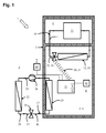
- Fig. 1 shows a schematically illustrated installed air conditioning device 1 for a building part 2 in a building 5.
- This has a heating circuit 10 for a heat transfer medium F comprising a heater 11 and a first heat exchanger 12.
- the first heat exchanger 12 is thermally coupled to the building part 2.
- This building part 2 is a room 4, in particular a climatically coupled room 4, for example a living room, bedroom or office, and the first heat exchanger 12 a arranged in this building part 2 radiator 13.
- the heater 11 is in turn arranged in another room 6, eg a boiler room.
- a controllable valve 15 is arranged in the heating circuit 10.
- the latter is designed as an electronic thermostat 16. It can be seen that the controllable valve 15 is associated with the first heat exchanger 12. It sits in the direction of flow of the heat transfer medium F immediately before the latter, and is especially in the building part. 2
- a heat pump 20 including a control unit 21, a peripheral heat exchanger 22 and an air-conditioning heat exchanger 23 is provided.
- This heat pump 20 has a refrigerant circuit 24 in which the peripheral heat exchanger 22 and the air-conditioning heat exchanger 23 are arranged.
- a compressor 26 In a first line 25 between the peripheral heat exchanger 22 and the air conditioning heat exchanger 23 is a compressor 26.
- a Heat pump 20 could be a split-climate device. So that the heat pump 20 can be used for heating and cooling, it is designed to be reversible. In particular, the conveying direction of the compressor 26 is reversible.
- expansion valve 28 can also be flowed through bidirectionally.
- a design the lines 24, 25 and the heat exchanger 22, 23 of the heat pump 20 to the different pressures is taken into account.
- the air-conditioning heat exchanger 23 is behind the compressor 26.
- the heat pump 20 is in a heating operation.
- the air conditioning heat exchanger 23 of the heat pump 20 is thermally coupled to the building part 2 as well as the first heat exchanger 12 of the heater 10.
- the peripheral heat exchanger 22 is thermally coupled to a periphery 3 of the building part 2.
- control unit 21 of the heat pump 20 has a connection to a temperature sensor 40 in the periphery 3. Shown here is a cable connection. However, a radio connection would be equally applicable. Another connected to the control unit 21 temperature sensor 41 can be found in the building part 2. Again, a cable connection is shown, however, also as a radio link can be realized.
- control unit 21 of the heat pump 20 is connected via a communication connection 30 with the controllable valve 15 in the heating circuit 10.
- This communication link 30 is a radio link 31.
- a setpoint value S of the room temperature R within the building area 2 and a switching temperature G are stored in the control unit.
- the method is additionally optimized by the fact that the switching temperature must be crossed by a defined buffer value before switching according to steps C) and D). As a result, the control unit 21 does not switch back and forth at short intervals between steps C) and D) at a peripheral temperature T which fluctuates around the switching temperature G. Efficiency losses during startup of the heat pump 20 and the heating circuit 10 are thus avoided.
- efficiency values of the heating circuit 10 and efficiency values of the heat pump 20 can be stored or stored in the control unit 21, and the control unit 21 calculates the switching temperature G based on the efficiency value of the heating circuit 10 and the efficiency value of the heat pump 20.
- CO2 efficiency values and cost-efficiency values at the control unit 21.
- the respectively necessary data for calculating the efficiency values can be entered into the control unit 21. These include the operating costs per unit heat of the heater 11, in particular their efficiency and the cost of a fossil fuel, as well as the operating costs of the heat pump, in particular their efficiency and current electricity costs.
- the CO2-emission-optimized switching temperature G results from the intersection of the CO2 emissions of the heat pump 20 and the CO2 emissions of the heating device 11 above the peripheral temperature T.
- the cost-optimized switching temperature G results from the intersection of the operating costs of the heat pump 20 and the operating costs of the heater 11 above the peripheral temperature T.
- the method also includes regulating the room temperature R to the desired value S when the heat pump 20 is activated with the same, and regulating the room temperature R to the desired value S with the heat pump 20 deactivated with the heating circuit 10.
- the control unit 21 transmits this Target value S to the controllable valve 15, in particular via the communication link 30.
- the method still provides for the heat pump 20 in reversible mode, i. in a cooling mode, to activate when the room temperature R exceeds an upper limit temperature. Consequently, the room temperature R of the building part 2 is cooled by means of the heat pump 20.
- This may also include a regulation to the setpoint value S.
- a second, in particular somewhat higher, desired value is stored in the control unit, which is controlled in the cooling mode. This lowers the operating cost of the air conditioning apparatus 1, and further, it does not switch between a heating operation and a cooling operation.
- a not shown but possible extension of the heating circuit 10 relates further in series and parallel heat exchanger in the building part 2. This is the case for example in several radiators in a room. At least each of the parallel heat exchangers should then be assigned a controllable valve, so that the flow of heat transfer medium through the respective heat exchanger can be regulated. Each of these valves should also be connected via a communication link to the control unit 21 of the heat pump 20. In this way, the control unit 21 can control all heat exchangers in the building part 2.
- the heater 11 may be part of other heating circuits that serve to heat other parts of the building. In these other parts of the building, in turn, a control unit and an air-conditioning heat exchanger equivalent to the first building part 2 could be present.
- the air conditioning heat exchangers are then either each part of a separate heat pump or connected in parallel or in series with the first heat exchanger of the heat pump shown.
- Fig. 2 there is a control diagram of the control unit 21 over the time t.
- the time t is shown on the abscissa.
- the course of the peripheral temperature T is shown on a first ordinate. This passes through at five times a switching temperature shown as a horizontal straight line G.
- Each of these timing triggers switching events that are output from the control unit 21.
- this relates to the activation ON and deactivation OFF of the heat pump 20, shown on a further ordinate.
- a switching of a valve 15 takes place in a heating circuit 10, from a closed position S1 to an enabled position S2 and vice versa, shown on a third ordinate.
- the peripheral temperature T Before the first crossing of the switching temperature G, the peripheral temperature T is below this. Here it is so cold that heating with the heating circuit 10 is more efficient than with the heat pump 20. Accordingly, the valve 15 is in Heating circuit 10 in an enabled position S2 and the heat pump 20 is deactivated OFF.
- the peripheral temperature T increases and finally passes through the switching temperature G. From this time, heating with the heat pump 20 is more efficient than with the heating circuit 10. Therefore, a signal is output from the control unit 21, which causes a closed position S2 of the controllable valve 15. At the same time, the heat pump 20 is activated ON.
- the peripheral temperature T finally falls again until it passes through the switching temperature G.
- the controllable valve 15 is again brought into an enabled position S2 and the heat pump 20 is deactivated.
Landscapes
- Engineering & Computer Science (AREA)
- General Engineering & Computer Science (AREA)
- Physics & Mathematics (AREA)
- Chemical & Material Sciences (AREA)
- Combustion & Propulsion (AREA)
- Mechanical Engineering (AREA)
- Thermal Sciences (AREA)
- Signal Processing (AREA)
- Mathematical Physics (AREA)
- Fuzzy Systems (AREA)
- Life Sciences & Earth Sciences (AREA)
- Sustainable Development (AREA)
- Remote Sensing (AREA)
- General Physics & Mathematics (AREA)
- Automation & Control Theory (AREA)
- Air Conditioning Control Device (AREA)
Abstract
Description
- Die Erfindung betrifft ein Verfahren zur Regelung eines Heizgerätes nach dem Oberbegriff des Patentanspruches 1.
- Wärmepumpen werden unter anderem zum Heizen und Kühlen von Gebäuden eingesetzt. Das thermodynamische Prinzip der Wärmepumpe ist allgemein bekannt und kommt insbesondere in Kühlschränken, Klimaanlagen, Split-Klima-Geräten oder Sole-Wärmepumpen zum Einsatz.
- Eine Wärmepumpe besteht dabei aus einem ersten Wärmetauscher zur Wärmeaufnahme und einem zweiten Wärmetauscher zur Wärmeabgabe. Die Wärmetauscher sind über zwei Verbindungsleitungen hydraulisch miteinander verbunden und bilden so einen Kreislauf für Kältemittel aus. In einer der Verbindungsleitungen ist ein Verdichter und in der anderen ein Expansionsventil angeordnet. Einer der Wärmetauscher liegt so in Strömungsrichtung des Kältemittels hinter dem Verdichter und einer hinter dem Expansionsventil.
- Bei einer Aktivierung des Verdichters, der meist einen elektrischen Antrieb aufweist, wird das Kältemittel hinter dem Verdichter komprimiert, wodurch sich die Temperatur des verdichteten Kältemittels erhöht. Beim Durchströmen des sich anschließenden Wärmetauschers gibt das warme Kältemittel Wärme ab. Auf der Seite des anderen Wärmetauschers wird das Kältemittel hingegen bei der Aktivierung des Verdichters entspannt. Dies senkt die Temperatur des entspannten Kältemittels, sodass das Kältemittel in diesem Wärmetauscher Wärme von einer Wärmequelle aufnehmen kann.
- Um den Wärmepumpenprozess zum Beheizen und zum Kühlen eines Gebäudes, einsetzen zu können, ist aus dem Stand der Technik weiterhin bekannt, die Strömungsrichtung des Kältemittels umkehrbar auszulegen. Bei derartigen reversiblen Wärmepumpen kehrt sich die Wärmeaufnahme und -abgabe der Wärmetauscher in Abhängigkeit von der Strömungsrichtung des Kältemittels um. Einer der Wärmetauscher korrespondiert dann zur Klimatisierung mit dem Gebäude und einer mit der Peripherie außerhalb des Gebäudes. In einem Heizbetrieb wird so Energie aus der Peripherie, insbesondere aus der Luft oder dem Boden, gewonnen und mittels eines KlimaWärmetauschers an die Raumluft eines Gebäudeteils abgegeben. Im Kühlbetrieb wird die Raumluft durch den Klima-Wärmetauscher gekühlt und mittels des Peripherie-Wärmetauschers an die Peripherie abgegeben.
- Oftmals werden Wärmepumpen jedoch nur zum Kühlen im Sommer eingesetzt und die Raumbeheizung im Winter, erfolgt mittels Radiatoren/Heizkörpern oder Fußbodenheizung in Kombination mit einem fossilen Heizgeräte.
- Außerdem sind Kombinationen von Wärmepumpen und fossilen Heizeinrichtungen bekannt, bei welchen die Kopplung hydraulisch erfolgt. Hierbei ist in den Wasserkreislauf eines Kessels ein Kältemittel-Wasser-Wärmeübertrager integriert, welcher mittels Kältemittelleitung mit der Wärmepumpe verbunden ist. Bei Außentemperaturen von zum Beispiel größer 0°C wird dann mit der Wärmepumpe geheizt, da diese Wärme effizienter bereitstellen kann. Ist die Außentemperaturen hingegen bspw. kleiner 0°C ist die Effizienz der Wärmepumpe eventuell schlechter als die des Kessels, so dass die Wärmebereitstellung durch den Kessel übernommen wird. Hierdurch kann die Effizienz bezüglich der Heizkosten oder zum Beispiel auch der CO2-Emissionen optimiert werden.
- Nachteilig ist an einer solchen Ausführung ist, dass in der Regel ein relativ hoher Installationsaufwand besteht. Dieser betrifft die Verlegung von elektrischen und hydraulischen Leitung und die Anschaffung eines speziellen Wärmespeichers mit Wärmetauscher für die Wärmepumpe. Derartige Bauarbeiten können einerseits vom Aufwand her umfangreich sein und andererseits auch zu erheblichen Kosten führen.
- Aufgabe der Erfindung ist es daher, die Mängel des Standes der Technik zu beseitigen und eine Klimatisierungsvorrichtung mit einer Wärmepumpe zu schaffen, die auf einfache Weise mit einer möglichst beliebigen weiteren Heizeinrichtung kombiniert ist, so dass geringe Heizkosten erzielbar sind, sowie die Installation mit wenig Aufwand, einfach und kostengünstig durchführbar ist. Zudem soll der Betrieb der Klimatisierungsvorrichtung möglichst ökologisch, zu jedem Zeitpunkt gesichert, einfach und sicher sein.
- Erfindungsgemäß wird dies mit den Merkmalen der Patentansprüche 1 und 8 gelöst. Vorteilhafte Weiterbildungen sind den Unteransprüchen zu entnehmen.
- Bei einer Klimatisierungsvorrichtung für einen Gebäudeteil, mit einem Heizkreislauf für ein Wärmeträgermedium, umfassend eine Heizeinrichtung und einen ersten Wärmetauscher, und mit einer Wärmepumpe, umfassend eine Regeleinheit, einen Peripherie-Wärmetauscher und einen Klima-Wärmetauscher, wobei der erste Wärmetauscher und der Klima-Wärmetauscher mit dem Gebäudeteil thermisch gekoppelt sind, und wobei der Peripherie-Wärmetauscher mit einer Peripherie des Gebäudeteils thermisch gekoppelt ist, sieht die Erfindung vor, dass die Regeleinheit der Wärmepumpe über eine Kommunikationsverbindung mit wenigstens einem regelbaren Ventil im Heizkreislauf verbunden ist.
- Dies ermöglicht eine Steuerung der Klimatisierungsvorrichtung, bei welcher in Abhängigkeit einer Peripherietemperatur eine Aktivierung der Wärmepumpe zur Beheizung des Gebäudeteils und ein Schließen des regelbaren Ventils im Heizkreislauf erfolgen, wenn die Peripherietemperatur größer ist als eine Umschalttemperatur, sowie ein Deaktivieren der Wärmepumpe und Freigabe des regelbaren Ventils im Heizkreislauf erfolgen, wenn die Peripherietemperatur geringer ist als die Umschalttemperatur. Somit kann die Beheizung immer dann durch die Wärmepumpe übernommen werden, wenn diese effizienter arbeitet als die Heizeinrichtung. Letztere ist dabei üblicherweise eine fossile Heizeinrichtung, da diese stets einsatzbereit sein sollte.
- Da nur eine Kommunikationsverbindung zwischen der Wärmepumpe und dem Heizkreislauf zu schaffen ist, nicht jedoch eine hydraulische, ist der Installationsaufwand äußerst gering. Die Erfindung erlaubt es somit Nutzern von Wärmepumpen, die eigentlich nur zum Kühlen angeschafft wurden, diese mit geringem Installations- und Kostenaufwand zum Heizen mit einer weiteren, insbesondere fossil betriebenen, Heizeinrichtung zu koppeln und dadurch Heizkosten zu sparen und/oder die CO2-Emissionen zu senken.
- Zur Optimierung der Heizkosten oder der CO2-Emissionen sollten in der Regeleinheit Effizienzwerte des Heizkreislaufs und Effizienzwerte der Wärmepumpe hinterlegbar sein. Basierend auf diesen kann dann die bestmögliche Umschalttemperatur bestimmt werden. Für deren Abgleich sollte die Regeleinheit weiterhin mit einem Temperatursensor zur Bestimmung einer Peripherietemperatur der Peripherie verbunden sein. Dieser kann mit einem Temperatursensor der Wärmepumpe übereinstimmen, welcher oftmals schon allein für die Regelung der Wärmepumpe vorgesehen ist.
- Eine Weiterbildung der Erfindung sieht vor, dass der erste Wärmetauscher ein Heizkörper oder eine Fußbodenheizung ist. Heizkörper und Fußbodenheizungen sind die am häufigsten eingesetzten Wärmetauscher für eine Kombination mit fossilen Heizeinrichtungen in Gebäuden. Gerade eine erfindungsgemäße Verbindung eines solchen Heizkreislaufs mit einer Wärmepumpe über eine Kommunikationsvorbindung erlaubt es somit einem sehr weiten Anwenderkreis, die Heizkosten auf einfache Art zu senken. Die Kombination mit weiteren Wärmetauschertypen ist jedoch nicht ausgeschlossen, so zum Beispiel mit einem in einer Wand integrierten Wärmetauscher.
- In einer besonderen Weiterbildung der Erfindung ist vorgesehen, dass das regelbare Ventil ein elektronisches Thermostat ist. Ein elektronisches Thermostatventil kann den Schließ- und den Freigabe-Befehl der Regeleinheit der Wärmepumpe einfach umsetzen, indem ein Aktuator das Ventil umschaltet. Heizeinrichtungen weisen typischer Weise entweder jeweils ein Thermostat pro Wärmetauscher auf, oder aber es ist ein Thermostat im zu beheizenden Gebäudeteil vorgesehen. Diese ohnehin notwendigen Thermostate können um die erfindungsgemäß notwendigen Anforderungen ergänzt werden.
- Bereits ohne die Kommunikationsverbindung als elektrisches Thermostat ausgebildete Thermostate werden entweder direkt bedient oder weisen eine Fernbedienung auf. Typische Funktionen solcher Thermostate sind unterschiedliche Wärmephasen an einem Tag und/oder unterschiedliche Wärmephasen an unterschiedlichen Tagen, zum Beispiel abhängig von Werktagen und freien Tagen. Elektronische Thermostate werden meist innerhalb des zu beheizenden Gebäudeteils eingesetzt und erfreuen sich zunehmender Beliebtheit. Durch eine Erweiterung von deren Funktion um die Kommunikationsverbindung mit der Regeleinheit der Wärmepumpe, ist eine sehr einfache Installation möglich. Solche Thermostate oder deren Fernbedienung können ggf. allein durch entsprechende Programmierung der Regeleinheit der Wärmepumpe angesteuert werden. Unter Umständen ist ein Softwareupdate des elektronischen Thermostates oder dessen Fernbedienung notwendig.
- Weiterhin besteht auch die Möglichkeit, mechanische Thermostate mit einer elektrisch angesteuerten Verschließeinheit zu kombinieren. Hierdurch erfolgt die Regelung der Temperatur durch das Thermostat nach wie vor mechanisch, zusätzlich ist jedoch ein elektrisches Schließen und Freigeben des Thermostat Ventils vorgesehen.
- Außerdem bietet sich ein Vertrieb von speziellen Thermostaten im Zusammenhang mit der Wärmepumpe an, um alle neuen Kunden unmittelbar auf die Koppelmöglichkeiten mit ihrem herkömmlichen Heizkreislauf aufzuklären. Die Installation eines um die erfindungsgemäßen Merkmale ergänzten Thermostats unterscheidet sich nicht von der eines herkömmlichen Thermostats. Bei Fußbodenheizungen kann beispielsweise ein an der Wand im Gebäudeteil montiertes Thermostat ersetzt werden, oder aber ein am Heizkörper montiertes Thermostat ist durch Drehen einer einzigen Überwurfmutter austauschbar. Ein Öffnen des Heizkreislaufs mit einhergehendem Austritt von Wärmeträgermedium ist jeweils nicht erforderlich.
- Besonders bevorzugt ist das Ventil dem ersten Wärmetauscher zugeordnet. Durch diese Zuordnung hat die Stellung des Ventils eine im Wesentlichen auf diesen ersten Wärmetauscher ausgerichtete Auswirkung. Es handelt sich somit um ein Ventil, welches nur den Durchfluss von Wärmeträgermedium im ersten Wärmetauscher regelt. Damit ist sichergestellt, dass die Regeleinheit der Wärmepumpe keine Wärmetauscher außerhalb des Wirkungsbereichs des Klimawärmetauschers - nämlich dem Gebäudeteil - regelt. Außerdem ist die Kommunikationsverbindung möglichst kurz ausgestaltbar. Diese muss nicht über den Gebäudeteil hinausgehen.
- Gemäß einer speziellen Weiterbildung der Erfindung ist das Ventil am ersten Wärmetauscher angeordnet. Der erste Wärmetauscher bietet meist gute Montagepositionen für das Ventil. Dies gilt insbesondere für unmittelbar an einem Heizkörper befestigte Thermostate, welche besonders leicht ersetzt werden können.
- Die Kommunikationsverbindung könnte eine Kabelverbindung sein. Dies bietet sich bei Neubauten oder Sanierungen an, insbesondere wenn vom Anlagenbetreiber auf geringe elektromagnetische Felder Wert gelegt wird.
- Vorzugsweise sieht die Erfindung jedoch vor, dass die Kommunikationsverbindung eine Funkverbindung ist. Eine Funkverbindung erfordert keinerlei Verbindung über ein Kabel zwischen dem Ventil im Heizkreislauf und der Regeleinheit der Wärmepumpe. Die Installation ist so besonders leicht und komfortabel durchführbar.
- Die erfindungsgemäß notwendigen zusätzlichen Funktionen für als Thermostat ausgebildete Ventile sind in der Herstellung gegenüber herkömmlichen über Funk angesteuerten elektrischen Thermostaten nicht teurer, da die Funkverbindung zur Regeleinheit keine zusätzlichen Bauteile erfordern. Dies gilt sowohl für direkte Funkverbindungen als auch für indirekte Funkverbindungen über eine Fernbedienung des elektrischen Thermostats. Beispielsweise wäre es möglich, die im Thermostat eingestellte und geforderte Raumtemperatur mittels der Regeleinheit temporär herabzusetzen, wenn mit der Wärmepumpe geheizt werden soll, bspw. auf 10 °C bei tatsächlich geforderten 23 °C. Damit würde dem Thermostat vermittelt, dass kein Heizbedarf besteht, und es würde schließen. Somit wird eine kostengünstige Vorrichtung zur Verfügung gestellt, welche geeignet ist, die Heizkosten zu senken.
- In einer bevorzugten Anordnung ist das regelbare Ventil in dem Gebäudeteil angeordnet. Damit ist die Kommunikationsverbindung möglichst kurz und einfach ausbildbar. Bei einer Kommunikationsverbindung mit Kabeln sind diese nur über kurze Distanzen zu verlegen. Funkverbindungen erfordern keine starken Sender und Empfänger. Das Funksignal wird außerdem kaum vom Wand- und Deckenaufbau des Gebäudes behindert, beispielsweise von einer Armierung.
- Um die Wärmepumpe nicht nur zum Heizen des Gebäudeteils einsetzen zu können, sollte die Wärmepumpe reversibel sein. Damit lässt sich die Förderrichtung des Kältemittels im Wärmepumpenkreislauf umkehren. Folglich kehrt sich auch die Wärmeabgabe und - aufnahme am Peripherie- und Klimawärmetauscher um. Der Klimawärmetauscher weist dann im Kühlbetrieb eine tiefere Temperatur als die Raumtemperatur im Gebäudeteil auf. Er überträgt dann Wärme aus dem Gebäudeteil auf das Kältemittel und führt diese über den Peripherie-Wärmetauscher an die Peripherie ab.
- Die Erfindung eignet sich auch in besonderem Maße für Wärmepumpen, welche als Split-Klima-Gerät ausgebildet sind. Diese sind in eine Inneneinheit und eine Außeneinheit aufgeteilt. Die Inneneinheit mit dem Klimawärmtauscher ist in dem Gebäudeteil und die Außeneinheit mit dem Peripherie-Wärmetauscher in der Peripherie angeordnet. Nachgerüstete, einfache Geräte sind unmittelbar gegenüberliegend an einer Gebäudewand installiert. Ein Loch in der Gebäudewand zur Durchführung der Kältemittelleitungen und ein elektrischer Anschluss sind hierfür ausreichend.
- Die Wärmepumpe sollte einen Kältemittelkreislauf aufweisen, in dem der Peripherie-Wärmetauscher und der Klima-Wärmetauscher angeordnet sind, wobei in einer ersten Leitung zwischen dem Peripherie-Wärmetauscher und dem Klima-Wärmetauscher ein Verdichter und in einer zweiten Leitung zwischen dem Peripherie-Wärmetauscher und dem Klima-Wärmetauscher ein Expansionsventil angeordnet ist.
- Eine Ausgestaltungsmöglichkeit betrifft den Verdichter, der ein Mehrwegeventil sowie eine Umkehrschleife umfassen kann. Damit ist die Strömungsrichtung des Kältemittels im Kältemittelkreislauf umkehrbar, ohne dass die Förderrichtung des eigentlichen Verdichters umgekehrt wird. Zusätzlich könnte das Expansionsventil aus zwei parallel angeordneten monodirektionalen Expansionsventilen ausgebildet sein, welche entgegengerichtet ausgerichtet sind. An einem der Expansionsventile kann das Kältemittel im Betrieb der Wärmepumpe expandieren, wohingegen das andere geschlossen ist.
- Ferner betrifft die Erfindung ein Verfahren zur Steuerung einer Klimatisierungsvorrichtung für einen Gebäudeteil, mit einem Heizkreislauf für ein Wärmeträgermedium umfassend eine Heizeinrichtung und einen ersten Wärmetauscher, und mit einer Wärmepumpe umfassend eine Regeleinheit, einen Peripherie-Wärmetauscher und einen Klima-Wärmetauscher, wobei der erste Wärmetauscher und der Klima-Wärmetauscher mit dem Gebäudeteil thermisch gekoppelt sind, wobei der Peripherie-Wärmetauscher mit einer Peripherie des Gebäudeteils thermisch gekoppelt ist, wobei die Regeleinheit der Wärmepumpe über eine Kommunikationsverbindung mit wenigstens einem regelbaren Ventil im Heizkreislauf verbunden ist, und wobei die Regeleinheit der Wärmepumpe folgende Schritte durchführt:
- A) Bestimmen einer Peripherietemperatur der Peripherie;
- B) Vergleichen der Peripherietemperatur mit einer Umschalttemperatur;
- C) Aktivieren der Wärmepumpe zur Beheizung des Gebäudeteils und Schließen des regelbaren Ventils im Heizkreislauf, wenn die Peripherietemperatur größer ist als die Umschalttemperatur;
- D) Deaktivieren der Wärmepumpe und Freigabe des regelbaren Ventils im Heizkreislauf, wenn die Peripherietemperatur geringer ist als die Umschalttemperatur.
- Da nur eine Kommunikationsverbindung zwischen der Wärmepumpe und dem Heizkreislauf zu schaffen ist, nicht jedoch eine hydraulische, ist der Installationsaufwand äußerst gering. Die Erfindung erlaubt es somit Nutzern von Wärmepumpen, die eigentlich nur zum Kühlen angeschafft wurden, diese mit geringem Installations- und Kostenaufwand zum Heizen mit einer weiteren, insbesondere fossil betriebenen, Heizeinrichtung zu koppeln und dadurch Heizkosten zu sparen und/oder die CO2-Emissionen zu senken.
- Dabei sollte die Regeleinheit mit einem Temperatursensor zur Bestimmung der Peripherietemperatur der Peripherie verbunden sein. Dieser kann mit einem Temperatursensor der Wärmepumpe übereinstimmen, welcher oftmals schon allein für die Regelung der Wärmepumpe vorgesehen ist.
- Eine Weiterbildung des erfindungsgemäßen Verfahrens sieht vor, dass in der Regeleinheit Effizienzwerte des Heizkreislaufs und Effizienzwerte der Wärmepumpe hinterlegt sind und die Regeleinheit eine Berechnung der Umschalttemperatur anhand des Effizienzwerts des Heizkreislaufs und des Effizienzwerts der Wärmepumpe durchführt. Somit obliegt die Umschalttemperatur nicht einer Vorgabe des Installateurs, sondern wird stets in optimaler Weise berechnet.
- Gemäß einer näheren Ausgestaltung sind die Effizienzwerte CO2-Effizienzwerte und die Umschalttemperatur ergibt sich aus dem Schnittpunkt der CO2-Emissionen der Wärmepumpe sowie der CO2-Emissionen der Heizeinrichtung über der Peripherietemperatur. Dieser Schnittpunkt ergibt sich dadurch, dass die CO2-Emissionen pro erzeugter Wärmemenge für das Heizen mit der Wärmepumpe mit sinkender Peripherietemperatur stark ansteigen. Dahingegen sind beispielsweise die CO2-Emissionen einer fossilen Heizeinrichtung pro erzeugter Wärmemenge relativ konstant. Der Schnittpunkt gibt somit die Umschalttemperatur an, unterhalb derer ein Heizen mit der Wärmepumpe aus CO2-Emissionsgründen nicht mehr sinnvoll ist. Die Klimatisierungsvorrichtung kann so mit minimalen CO2-Emissionen betrieben werden. Die Daten zur Berechnung der Effizienzwerte sollten hierfür in die Regeleinheit eingebbar sein. Auf diese Weise ist die Umschalttemperatur für jede Kombination aus Heizeinrichtung und Wärmepumpe optimal berechenbar.
- In einer anderen Ausgestaltung sind die Effizienzwerte Kosten-Effizienzwerte und die Umschalttemperatur ergibt sich aus dem Schnittpunkt der Betriebskosten der Wärmepumpe sowie der Betriebskosten der Heizeinrichtung über der Peripherietemperatur. Dieser Schnittpunkt ergibt sich dadurch, dass die Kosten pro erzeugter Wärmemenge für das Heizen mit der Wärmepumpe mit sinkender Peripherietemperatur stark ansteigen. Dahingegen sind beispielsweise die Kosten einer fossilen Heizeinrichtung pro erzeugter Wärmemenge relativ konstant. Der Schnittpunkt gibt somit die Umschalttemperatur an, unterhalb derer ein Heizen mit der Wärmepumpe aus Kostengründen nicht mehr sinnvoll ist. So können beispielsweise auch aktuelle Kosten für Strom und Brennstoff berücksichtigt werden, sodass die Umschalttemperatur entsprechend korrigiert wird. Insbesondere bei einer elektrisch betriebenen Wärmepumpe und einer fossil betriebenen Heizeinrichtung würde die Umschalttemperatur bei steigenden Stromkosten steigen und bei sinkenden Stromkosten sinken. Steigen dahingegen die Kosten für den fossilen Brennstoff überproportional, sinkt die Umschalttemperatur. Vice versa steigt die Umschalttemperatur bei sinkenden Brennstoffkosten. Die Betriebskosten der Klimatisierungsvorrichtung sind so besonders gering. Die Daten zur Berechnung der Effizienzwerte sollten hierfür in die Regeleinheit eingebbar sein. Auf diese Weise ist die Umschalttemperatur für jede Kombination aus Heizeinrichtung und Wärmepumpe optimal berechenbar.
- Vorzugsweise wird die Regeleinheit so ausgestaltet, dass zwischen CO2-Effizienzwerten und Kosten-Effizienzwerten ausgewählt werden kann. Somit eignet sich die erfindungsgemäße Klimatisierungsvorrichtung sowohl für Betreiber mit Kostenfokus als auch für Betreiber mit ökologischem Fokus. Die Regeleinheit könnte zusätzlich auch eine Mischkalkulation der Umschalttemperatur basierend auf CO2-Effizienzwerten und Kosten-Effizienzwerten durchführen, indem der Nutzer Präferenzen für die beiden Ziele eingibt.
- Um bei Peripheriebedingungen in unmittelbarer Umgebung der Umschalttemperatur nicht ständig zwischen einem Heizen mit der Wärmepumpe und der Heizeinrichtung zu wechseln, kann eine Mindestbetriebszeit nach einem Schaltvorgang des regelbaren Ventils vorgesehen sein. Während dieser würde ein erneutes Umschalten des Ventils blockiert.
- Alternativ bietet es sich an, einen Pufferwert vorzusehen, um welchen die Umschalttemperatur durchschritten werden muss, bevor ein Umschalten des regelbaren Ventils erfolgt, insbesondere gemäß der Schritte C) und D). Dieser Pufferwert könnte beispielsweise zwischen 0,5 °C und 2 °C liegen.
- Das erfindungsgemäße Verfahren kann dadurch ergänzt werden, dass ein Regeln einer Raumtemperatur auf einen Soll-Wert bei aktivierter Wärmepumpe mit der selbigen erfolgt. Somit wird der Wärmeanforderung des Gebäudeteils bestmöglich Rechnung getragen. Außerdem wird nicht unnötig viel geheizt, wodurch die Heizkosten gering sind.
- Weiterhin erfolgt bevorzugt in äquivalenter Weise ein Regeln der Raumtemperatur auf einen Soll-Wert bei deaktivierter Wärmepumpe mit dem Heizkreislauf. Diese Regelung erfolgt meist mittels eines Thermostats. Ergänzend ist oftmals eine Nachtabschaltung vorgesehen, welche das Heizen bei Nacht unterbindet. Eine Nachtabschaltung kann ebenso für die Wärmepumpe vorgesehen sein. Dies senkt die Heizkosten, da bei Nacht ein geringerer Wärmebedarf für den Gebäudeteil vorliegen kann.
- Um eine zentrale Einstellung der Gebäudetemperatur vornehmen zu können, sollte die Regeleinheit der Wärmepumpe den Soll-Wert an das regelbare Ventil übermitteln. Dies stellt sicher, dass die Wärmepumpe und der Heizkreislauf aufeinander abgestimmt sind und nicht auf unterschiedliche Temperaturen regeln. Außerdem kann ein Bediener alle Eingaben komfortabel an einem Ort vorgeben.
- Ferner betrifft die Erfindung eine Verwendung einer Klimatisierungsvorrichtung zur Klimatisierung eines Gebäudeteils, mit einem Heizkreislauf für ein Wärmeträgermedium umfassend eine Heizeinrichtung und einen ersten Wärmetauscher, und mit einer Wärmepumpe umfassend eine Regeleinheit, einen Peripherie-Wärmetauscher und einen Klima-Wärmetauscher, wobei der erste Wärmetauscher und der Klima-Wärmetauscher mit dem Gebäudeteil thermisch gekoppelt sind, wobei der Peripherie-Wärmetauscher mit einer Peripherie des Gebäudeteils thermisch gekoppelt ist, und wobei die Regeleinheit der Wärmepumpe über eine Kommunikationsverbindung mit wenigstens einem regelbaren Ventil im Heizkreislauf verbunden ist.
- Die Zeichnungen stellen Ausführungsbeispiele der Erfindung dar. Es zeigt:
- Fig. 1:
- eine schematisch dargestellte installierte Klimatisierungsvorrichtung und
- Fig. 2
- ein Regeldiagramm einer Regeleinheit einer Wärmepumpe über der Zeit.
-
Fig. 1 zeigt eine schematisch dargestellte installierte Klimatisierungsvorrichtung 1 für einen Gebäudeteil 2 in einem Gebäude 5. Diese weist einen Heizkreislauf 10 für ein Wärmeträgermedium F umfassend eine Heizeinrichtung 11 und einen ersten Wärmetauscher 12 auf. Der erste Wärmetauscher 12 ist mit dem Gebäudeteil 2 thermisch gekoppelt. Dieser Gebäudeteil 2 ist ein Raum 4, insbesondere ein klimatisch gekoppelter Raum 4, bspw. ein Wohnzimmer, Schlafzimmer oder Büro, sowie der erste Wärmetauscher 12 ein in diesem Gebäudeteil 2 angeordneter Heizkörper 13. Die Heizeinrichtung 11 ist wiederum in einem anderen Raum 6 angeordnet, bspw. einem Heizraum. - Weiterhin ist in dem Heizkreislauf 10 ein regelbares Ventil 15 angeordnet. Letzteres ist als elektronisches Thermostat 16 ausgebildet. Man erkennt, dass das regelbare Ventil 15 dem ersten Wärmetauscher 12 zugeordnet ist. Es sitzt in Strömungsrichtung des Wärmeträgermediums F unmittelbar vor letzterem, und liegt insbesondere auch in dem Gebäudeteil 2.
- Außerdem ist eine Wärmepumpe 20 umfassend eine Regeleinheit 21, einen Peripherie-Wärmetauscher 22 und einen Klima-Wärmetauscher 23 vorgesehen. Diese Wärmepumpe 20 weist einen Kältemittelkreislauf 24 auf, in dem der Peripherie-Wärmetauscher 22 und der Klima-Wärmetauscher 23 angeordnet sind. In einer ersten Leitung 25 zwischen dem Peripherie-Wärmetauscher 22 und dem Klima-Wärmetauscher 23 befindet sich ein Verdichter 26. Außerdem befindet sich in einer zweiten Leitung 27 zwischen dem Peripherie-Wärmetauscher 22 und dem Klima-Wärmetauscher 23 ein Expansionsventil 28. Bei einer solchen Wärmepumpe 20 könnte es sich um ein Split-Klima-Gerät handeln. Damit die Wärmepumpe 20 zum Heizen und Kühlen eingesetzt werden kann, ist sie reversibel ausgebildet. Insbesondere ist die Förderrichtung des Verdichters 26 umkehrbar. Zusätzlich ist auch das Expansionsventil 28 bidirektional durchströmbar. Eine Auslegung der Leitungen 24, 25 sowie der Wärmetauscher 22, 23 der Wärmepumpe 20 an die unterschiedlichen Drücke ist dabei berücksichtigt. In der dargestellten Strömungsrichtung des Kältemittels K liegt der Klima-Wärmetauscher 23 hinter dem Verdichter 26. Damit befindet sich die Wärmepumpe 20 in einem Heizbetrieb.
- Der Klima-Wärmetauscher 23 der Wärmepumpe 20 ist ebenso wie der erste Wärmetauscher 12 der Heizeinrichtung 10 mit dem Gebäudeteil 2 thermisch gekoppelt. Beide dienen damit der Klimatisierung desselben Gebäudeteils 2. Dahingegen ist der Peripherie-Wärmetauscher 22 mit einer Peripherie 3 des Gebäudeteils 2 thermisch gekoppelt.
- Weiterhin weist die Regeleinheit 21 der Wärmepumpe 20 eine Verbindung zu einem Temperatursensor 40 in der Peripherie 3 auf. Dargestellt ist hierbei eine Kabelverbindung. Eine Funkverbindung wäre jedoch ebenso einsetzbar. Ein weiterer mit der Regeleinheit 21 verbundener Temperatursensor 41 findet sich im Gebäudeteil 2. Auch hier ist eine Kabelverbindung gezeigt, die jedoch ebenfalls als Funkverbindung realisierbar ist.
- Schließlich ist die Regeleinheit 21 der Wärmepumpe 20 über eine Kommunikationsverbindung 30 mit dem regelbaren Ventil 15 im Heizkreislauf 10 verbunden. Diese Kommunikationsverbindung 30 ist eine Funkverbindung 31.
- Zur Regelung der Klimatisierungsvorrichtung 1 sind in der Regeleinheit ein Soll-Wert S der Raumtemperatur R innerhalb des Gebäudebereichs 2 sowie eine Umschalttemperatur G hinterlegt.
- Mittels dieser Klimatisierungsvorrichtung 1 ist nunmehr ein Verfahren durchführbar, bei welchem die Regeleinheit 21 der Wärmepumpe 20 folgende Schritte durchführt:
- A) Bestimmen einer Peripherietemperatur T der Peripherie 3, insbesondere mittels des Temperatursensors 40 in der Peripherie 3;
- B) Vergleichen der Peripherietemperatur T mit einer Umschalttemperatur G;
- C) Aktivieren ON der Wärmepumpe 20 zur Beheizung des Gebäudeteils 2 und Schließen S1 des regelbaren Ventils 15 im Heizkreislauf 10, wenn die Peripherietemperatur T größer ist als die Umschalttemperatur G, wobei das Schließen des regelbaren Ventils 15 insbesondere durch Ausgabe eines Funksignals erfolgt;
- D) Deaktivieren OFF der Wärmepumpe 20 und Freigabe S2 des regelbaren Ventils 15 im Heizkreislauf 10, wenn die Peripherietemperatur T geringer ist als die Umschalttemperatur G, wobei die Freigabe des regelbaren Ventils 15 insbesondere durch Ausgabe eines Funksignals erfolgt.
- Das Verfahren ist zusätzlich dadurch optimiert, dass die Umschalttemperatur um einen definierten Pufferwert durchschritten werden muss, bevor eine Umschaltung gemäß der Schritte C) und D) erfolgt. Die Regeleinheit 21 schaltet hierdurch bei einer Peripherietemperatur T, welche um die Umschalttemperatur G schwankt, nicht in kurzen Zeitabständen zwischen den Schritten C) und D) hin und her. Effizienzverluste beim Anlauf der Wärmepumpe 20 und des Heizkreislaufs 10 werden so vermieden.
- Weiterhin sind in der Regeleinheit 21 Effizienzwerte des Heizkreislaufs 10 und Effizienzwerte der Wärmepumpe 20 hinterlegbar, bzw. hinterlegt und die Regeleinheit 21 führt eine Berechnung der Umschalttemperatur G anhand des Effizienzwerts des Heizkreislaufs 10 und des Effizienzwerts der Wärmepumpe 20 durch.
- Insbesondere kann an der Regeleinheit 21 zwischen CO2-Effizienzwerten und Kosten-Effizienzwerten ausgewählt werden. Die jeweils notwendigen Daten zur Berechnung der Effizienzwerte sind in die Regeleinheit 21 eingebbar. Hierzu gehören die Betriebskosten pro Wärmeeinheit der Heizeinrichtung 11, insbesondere deren Effizienz und die Kosten für einen fossilen Brennstoff, sowie die Betriebskosten der Wärmepumpe, insbesondere deren Effizienz und der aktuellen Stromkosten.
- Die CO2-Emissionen-optimierte Umschalttemperatur G ergibt sich aus dem Schnittpunkt der CO2-Emissionen der Wärmepumpe 20 sowie der CO2-Emissionen der Heizeinrichtung 11 über der Peripherietemperatur T.
- Außerdem ergibt sich die kostenoptimierte Umschalttemperatur G aus dem Schnittpunkt der Betriebskosten der Wärmepumpe 20 sowie der Betriebskosten der Heizeinrichtung 11 über der Peripherietemperatur T.
- Das Verfahren umfasst auch noch ein Regeln der Raumtemperatur R auf den Soll-Wert S bei aktivierter Wärmepumpe 20 mit der selbigen, sowie ein Regeln der Raumtemperatur R auf den Soll-Wert S bei deaktivierter Wärmepumpe 20 mit dem Heizkreislauf 10. Die Regeleinheit 21 übermittelt diesen Soll-Wert S an das regelbare Ventil 15, insbesondere über die Kommunikationsverbindung 30.
- Schließlich sieht das Verfahren noch vor, die Wärmepumpe 20 im reversiblen Modus, d.h. in einem Kühlbetrieb, zu aktivieren, wenn die Raumtemperatur R eine obere Grenztemperatur überschreitet. Folglich wird die Raumtemperatur R des Gebäudeteils 2 mittels der Wärmepumpe 20 gekühlt. Dies kann ebenso eine Regelung auf den Soll-Wert S umfassen. Bevorzugt wird jedoch ein zweiter, insbesondere etwas höherer, Soll-Wert in der Regeleinheit hinterlegt, auf den im Kühlbetrieb geregelt wird. Dies senkt die Betriebskosten der Klimatisierungsvorrichtung 1 und außerdem wird nicht zwischen einem Heizbetrieb und einem Kühlbetrieb hin und her geschaltet.
- Eine nicht dargestellte aber mögliche Erweiterung des Heizkreislaufs 10 betrifft weitere in Reihe und parallel angeordnete Wärmetauscher im Gebäudeteil 2. Dies ist zum Beispiel bei mehreren Heizkörpern in einem Raum der Fall. Wenigstens jedem der parallel angeordneten Wärmetauscher sollte dann ein regelbares Ventil zugeordnet sein, sodass der Durchfluss von Wärmeträgermedium durch den jeweiligen Wärmetauscher regelbar ist. Jedes dieser Ventile sollte auch über eine Kommunikationsverbindung mit der Regeleinheit 21 der Wärmepumpe 20 verbunden sein. Auf diese Weise kann die Regeleinheit 21 alle Wärmetauscher in dem Gebäudeteil 2 ansteuern. Außerdem kann die Heizeinrichtung 11 Bestandteil weiterer Heizkreisläufe sein, die der Beheizung weiterer Gebäudeteile dienen. In diesen weiteren Gebäudeteilen könnten wiederum eine Regeleinheit und ein Klima-Wärmetauscher äquivalent zum ersten Gebäudeteil 2 vorhanden sein. Die Klima-Wärmetauscher sind dann entweder jeweils Bestandteil einer separaten Wärmepumpe oder aber parallel oder in Reihe zum ersten Wärmetauscher der gezeigten Wärmepumpe geschaltet.
- In
Fig. 2 findet sich ein Regeldiagramm der Regeleinheit 21 über der Zeit t. Die Zeit t ist dabei auf der Abszisse dargestellt. Auf einer ersten Ordinate ist der Verlauf der Peripherietemperatur T gezeigt. Diese durchschreitet an fünf Zeitpunkten eine als horizontale Gerade dargestellte Umschalttemperatur G. Jeder dieser Zeitpunkte löst Schaltereignisse aus, die von der Regeleinheit 21 ausgegeben werden. Zum einen betrifft dies die Aktivierung ON und Deaktivierung OFF der Wärmepumpe 20, dargestellt auf einer weiteren Ordinate. Zum anderen erfolgt ein Umschalten eines Ventils 15 in einem Heizkreislauf 10, von einer Geschlossenstellung S1 in eine Freigegebenstellung S2 und umgekehrt, dargestellt auf einer dritten Ordinate. - Vor der ersten Durchschreitung der Umschalttemperatur G liegt die Peripherietemperatur T unterhalb von dieser. Hier ist es so kalt, dass ein Heizen mit dem Heizkreislauf 10 effizienter ist als mit der Wärmepumpe 20. Entsprechend befindet sich das Ventil 15 im Heizkreislauf 10 in einer Freigegebenstellung S2 und die Wärmepumpe 20 ist deaktiviert OFF.
- Wie man erkennt, steigt die Peripherietemperatur T an und durchschreitet die Umschalttemperatur G schließlich. Ab diesem Zeitpunkt ist das Heizen mit der Wärmepumpe 20 effizienter als mit dem Heizkreislauf 10. Es wird daher ein Signal von der Regeleinheit 21 ausgegeben, welches eine Geschlossenstellung S2 des regelbaren Ventils 15 veranlasst. Gleichzeitig wird die Wärmepumpe 20 aktiviert ON.
- Nach längerer Zeit fällt die Peripherietemperatur T schließlich wieder bis sie die Umschalttemperatur G durchschreitet. Hier wird das regelbare Ventil 15 erneut in eine Freigegebenstellung S2 gebracht sowie die Wärmepumpe 20 deaktiviert.
- Nicht erkennbar ist hierbei die Regelung auf eine vorgegebene Raumtemperatur R welche jeweils in den verschiedenen Phasen erfolgt, entweder mittels Regelung des Heizkreislaufs 10 oder der Regelung der Wärmepumpe 20. Außerdem wurde auf die Darstellung einer Umschaltung von einem Heizbetrieb in einen Kühlbetrieb verzichtet.
-
- 1
- Klimatisierungsvorrichtung
- 2
- Gebäudeteil
- 3
- Peripherie
- 4
- Raum
- 5
- Gebäude
- 6
- zweiter Raum
- 10
- Heizkreislauf
- 11
- Heizeinrichtung
- 12
- erster Wärmetauscher
- 13
- Heizkörper
- 15
- Ventil
- 16
- Thermostat
- 20
- Wärmepumpe
- 21
- Regeleinheit
- 22
- Peripherie-Wärmetauscher
- 23
- Klima-Wärmetauscher
- 24
- Kältemittelkreislauf
- 25
- erste Leitung
- 26
- Verdichter
- 27
- zweite Leitung
- 28
- Expansionsventil
- 30
- Kommunikationsverbindung
- 31
- Funkverbindung
- 40
- Temperatursensor (Peripherie)
- 41
- Temperatursensor (Gebäudeteil)
- F
- Wärmeträgermedium
- G
- Umschalttemperatur
- K
- Kältemittel
- OFF
- deaktive Wärmepumpe
- ON
- aktive Wärmepumpe
- R
- Raumtemperatur
- S
- Soll-Wert
- S1
- Geschlossenstellung des Ventils
- S2
- Freigegebenstellung des Ventils
- t
- Zeit
- T
- Peripherietemperatur
Claims (12)
- Klimatisierungsvorrichtung (1) für einen Gebäudeteil (2), mit einem Heizkreislauf (10) für ein Wärmeträgermedium (F), umfassend eine Heizeinrichtung (11) und einen ersten Wärmetauscher (12), und mit einer Wärmepumpe (20), umfassend eine Regeleinheit (21), einen Peripherie-Wärmetauscher (22) und einen Klima-Wärmetauscher (23), wobei der erste Wärmetauscher (12) und der Klima-Wärmetauscher (23) mit dem Gebäudeteil (2) thermisch gekoppelt sind, und wobei der Peripherie-Wärmetauscher (22) mit einer Peripherie (3) des Gebäudeteils (2) thermisch gekoppelt ist,
dadurch gekennzeichnet, dass die Regeleinheit (21) der Wärmepumpe (20) über eine Kommunikationsverbindung (30) mit wenigstens einem regelbaren Ventil (15) im Heizkreislauf (10) verbunden ist. - Klimatisierungsvorrichtung (1) nach Anspruch 1,
dadurch gekennzeichnet, dass der erste Wärmetauscher (12) ein Heizkörper (13) oder eine Fußbodenheizung ist. - Klimatisierungsvorrichtung (1) nach einem der Ansprüche 1 oder 2,
dadurch gekennzeichnet, dass das regelbare Ventil (15) ein elektronisches Thermostat (16) ist. - Klimatisierungsvorrichtung (1) nach einem der vorhergehenden Ansprüche,
dadurch gekennzeichnet, dass das Ventil (15) dem ersten Wärmetauscher (12) zugeordnet ist. - Klimatisierungsvorrichtung (1) nach einem der vorhergehenden Ansprüche,
dadurch gekennzeichnet, dass das Ventil (15) am ersten Wärmetauscher (12) angeordnet ist. - Klimatisierungsvorrichtung (1) nach einem der vorhergehenden Ansprüche,
dadurch gekennzeichnet, dass die Kommunikationsverbindung (30) eine Funkverbindung (31) ist. - Klimatisierungsvorrichtung (1) nach einem der vorhergehenden Ansprüche,
dadurch gekennzeichnet, dass das regelbare Ventil (15) in dem Gebäudeteil (2) angeordnet ist. - Verfahren zur Steuerung einer Klimatisierungsvorrichtung (1) nach einem der Ansprüche 1 bis 7, wobei die Regeleinheit (21) der Wärmepumpe (20) folgende Schritte durchführt:A) Bestimmen einer Peripherietemperatur (T) der Peripherie (3);B) Vergleichen der Peripherietemperatur (T) mit einer Umschalttemperatur (G);C) Aktivieren (ON) der Wärmepumpe (20) zur Beheizung des Gebäudeteils (2) und Schließen (S1) des regelbaren Ventils (15) im Heizkreislauf (10), wenn die Peripherietemperatur (T) größer ist als die Umschalttemperatur (G);D) Deaktivieren (OFF) der Wärmepumpe (20) und Freigabe (S2) des regelbaren Ventils (15) im Heizkreislauf (10), wenn die Peripherietemperatur (T) geringer ist als die Umschalttemperatur (G).
- Verfahren nach Anspruch 8,
dadurch gekennzeichnet, dass in der Regeleinheit (21) Effizienzwerte des Heizkreislaufs (10) und Effizienzwerte der Wärmepumpe (20) hinterlegt sind und die Regeleinheit (21) eine Berechnung der Umschalttemperatur (G) anhand des Effizienzwerts des Heizkreislaufs (10) und des Effizienzwerts der Wärmepumpe (20) durchführt. - Verfahren nach Anspruch 9,
dadurch gekennzeichnet, dass die Effizienzwerte CO2-Effizienzwerte sind und sich die Umschalttemperatur (G) aus dem Schnittpunkt der CO2-Emissionen der Wärmepumpe (20) sowie der CO2-Emissionen der Heizeinrichtung (11) über der Peripherietemperatur (T) ergibt. - Verfahren nach Anspruch 10,
dadurch gekennzeichnet, dass die Effizienzwerte Kosten-Effizienzwerte sind und sich die Umschalttemperatur (G) aus dem Schnittpunkt der Betriebskosten der Wärmepumpe (20) sowie der Betriebskosten der Heizeinrichtung (11) über der Peripherietemperatur (T) ergibt. - Verwendung einer Klimatisierungsvorrichtung (1) nach einem der Ansprüche 1 bis 7 zur Klimatisierung eines Gebäudeteils (2).
Applications Claiming Priority (1)
| Application Number | Priority Date | Filing Date | Title |
|---|---|---|---|
| DE102011120442A DE102011120442A1 (de) | 2011-12-07 | 2011-12-07 | Klimatisierungsvorrichtung mit einer Heizeinrichtung und einer Wärmepumpe, sowie ein Verfahren zu deren Betrieb |
Publications (2)
| Publication Number | Publication Date |
|---|---|
| EP2602560A1 true EP2602560A1 (de) | 2013-06-12 |
| EP2602560B1 EP2602560B1 (de) | 2015-02-25 |
Family
ID=47294743
Family Applications (1)
| Application Number | Title | Priority Date | Filing Date |
|---|---|---|---|
| EP12195469.7A Active EP2602560B1 (de) | 2011-12-07 | 2012-12-04 | Klimatisierungsvorrichtung mit einer Heizeinrichtung und einer Wärmepumpe, sowie ein Verfahren zu deren Betrieb |
Country Status (2)
| Country | Link |
|---|---|
| EP (1) | EP2602560B1 (de) |
| DE (1) | DE102011120442A1 (de) |
Cited By (3)
| Publication number | Priority date | Publication date | Assignee | Title |
|---|---|---|---|---|
| CN109059143A (zh) * | 2018-06-19 | 2018-12-21 | 广东美的暖通设备有限公司 | 室内制热方法及装置 |
| WO2024008753A1 (fr) * | 2022-07-05 | 2024-01-11 | Accenta | Procédé et installation pour fournir de l'énergie notamment thermique, peu carbonée, dans au moins un bâtiment ou analogue, et système s'y rapportant. |
| EP4546077A1 (de) | 2023-10-26 | 2025-04-30 | Daikin Europe N.V. | Temperatursteuerungssystem und -verfahren |
Families Citing this family (2)
| Publication number | Priority date | Publication date | Assignee | Title |
|---|---|---|---|---|
| CN116576498B (zh) * | 2023-05-22 | 2025-12-02 | 浙江英集动力科技有限公司 | 基于空气源热泵和楼宇换热机组的供热系统协调控制方法 |
| DE102024212183A1 (de) * | 2024-12-19 | 2026-06-25 | Robert Bosch Gesellschaft mit beschränkter Haftung | Kompaktwärmepumpe und Gebäudeklimatisierungssystem |
Citations (1)
| Publication number | Priority date | Publication date | Assignee | Title |
|---|---|---|---|---|
| US4178988A (en) * | 1977-11-10 | 1979-12-18 | Carrier Corporation | Control for a combination furnace and heat pump system |
-
2011
- 2011-12-07 DE DE102011120442A patent/DE102011120442A1/de not_active Ceased
-
2012
- 2012-12-04 EP EP12195469.7A patent/EP2602560B1/de active Active
Patent Citations (1)
| Publication number | Priority date | Publication date | Assignee | Title |
|---|---|---|---|---|
| US4178988A (en) * | 1977-11-10 | 1979-12-18 | Carrier Corporation | Control for a combination furnace and heat pump system |
Cited By (4)
| Publication number | Priority date | Publication date | Assignee | Title |
|---|---|---|---|---|
| CN109059143A (zh) * | 2018-06-19 | 2018-12-21 | 广东美的暖通设备有限公司 | 室内制热方法及装置 |
| WO2024008753A1 (fr) * | 2022-07-05 | 2024-01-11 | Accenta | Procédé et installation pour fournir de l'énergie notamment thermique, peu carbonée, dans au moins un bâtiment ou analogue, et système s'y rapportant. |
| FR3137744A1 (fr) * | 2022-07-05 | 2024-01-12 | Accenta | Procédé et installation pour fournir de l’énergie notamment thermique, peu carbonée, dans au moins un bâtiment ou analogue, et système s’y rapportant. |
| EP4546077A1 (de) | 2023-10-26 | 2025-04-30 | Daikin Europe N.V. | Temperatursteuerungssystem und -verfahren |
Also Published As
| Publication number | Publication date |
|---|---|
| DE102011120442A1 (de) | 2013-06-13 |
| EP2602560B1 (de) | 2015-02-25 |
Similar Documents
| Publication | Publication Date | Title |
|---|---|---|
| EP2580630B1 (de) | Verfahren zum einstellen des volumenstromes von heiz- und/oder kühlmedium durch raumwärmetauscher einer heizungs- bzw. kühlanlage | |
| EP2151578B1 (de) | Umwälzpumpenaggregat | |
| EP2602560B1 (de) | Klimatisierungsvorrichtung mit einer Heizeinrichtung und einer Wärmepumpe, sowie ein Verfahren zu deren Betrieb | |
| EP3443228B1 (de) | Kreiselpumpenaggregat und verfahren zu seiner betriebseinstellung | |
| DE202014103193U1 (de) | Zirkulationsleitung für Kaltwasser | |
| WO2009146856A1 (de) | Klimaanlage zur konditionierung mehrerer fluide | |
| DE202017105111U1 (de) | Wärmegewinnungsanlage und Wärmetauschereinheit | |
| EP2057419A1 (de) | Verfahren zum betrieb eines rohrnetzes | |
| EP2175206B1 (de) | Verfahren zur Temperierung von Räumen eines Gebäudes | |
| EP2802822B1 (de) | Verfahren zur geregelten luftkonditionierung in einer lufttechnischen anlage und vorrichtung | |
| EP0184887A1 (de) | Belüftungsvorrichtung für Gebäude, insbesondere für zugfrei ausgebildete Wohnungen | |
| EP2896900B1 (de) | Verfahren zum steuern einer kühl- oder wärmeleistung für ein wärme-/kältesystem mit mehreren quellen und steuergerät zur ausführung des verfahrens | |
| EP2204619B1 (de) | Vorrichtung und verfahren für einen optimierten betrieb eines klimatisierungssystems und klimatisierungssystem | |
| DE10315802B4 (de) | Anordnung zur Versorgung von Räumen eines Gebäudes mit temperierter Luft | |
| DE102007016345A1 (de) | Lüftungsanlage mit einer Vorrichtung zum Heizen und/oder Kühlen von Gebäuden | |
| DE3539328A1 (de) | Verfahren zum aufheizen wenigstens zweier verbraucher | |
| DE2756860C3 (de) | Steuersystem fur die Heizungsanlage eines Mehrfamilienhauses | |
| EP0192227A2 (de) | Verfahren zur Regelung der Temperatur in Räumen | |
| DE102021200036A1 (de) | Ein integriertes Wärmespeichersystem, das zusätzliche im Kältemittelkreislauf einer Wärmepumpe eingebrachte Energie speichert | |
| EP2950006B1 (de) | Raumtemperatur-regelung für eine flächenheizung | |
| DE102014202311A1 (de) | Verfahren zum Synchronisieren einer Thermoanlage mit einem Thermosystem | |
| DE202020106754U1 (de) | Gebäude mit mehreren beheizbaren Räumen | |
| DE20318592U1 (de) | Hauskühlung | |
| DE102011118624A1 (de) | Verfahren zum Steuern eines Versorgungssystems zur Wärmeversorgnung einer Einheit aus Wohnhaus und Schwimmhalle mit einer Wärmepumpe sowie ein dazu geeignetes Versorgungssystem | |
| DE9414055U1 (de) | Zentralheizsystem für Gebäude |
Legal Events
| Date | Code | Title | Description |
|---|---|---|---|
| PUAI | Public reference made under article 153(3) epc to a published international application that has entered the european phase |
Free format text: ORIGINAL CODE: 0009012 |
|
| AK | Designated contracting states |
Kind code of ref document: A1 Designated state(s): AL AT BE BG CH CY CZ DE DK EE ES FI FR GB GR HR HU IE IS IT LI LT LU LV MC MK MT NL NO PL PT RO RS SE SI SK SM TR |
|
| AX | Request for extension of the european patent |
Extension state: BA ME |
|
| 17P | Request for examination filed |
Effective date: 20131212 |
|
| RBV | Designated contracting states (corrected) |
Designated state(s): AL AT BE BG CH CY CZ DE DK EE ES FI FR GB GR HR HU IE IS IT LI LT LU LV MC MK MT NL NO PL PT RO RS SE SI SK SM TR |
|
| RIC1 | Information provided on ipc code assigned before grant |
Ipc: F24F 11/00 20060101ALI20140716BHEP Ipc: F24D 3/00 20060101ALI20140716BHEP Ipc: F24D 19/10 20060101AFI20140716BHEP Ipc: G05D 23/00 20060101ALI20140716BHEP Ipc: G05D 23/19 20060101ALI20140716BHEP Ipc: F24F 5/00 20060101ALI20140716BHEP |
|
| GRAP | Despatch of communication of intention to grant a patent |
Free format text: ORIGINAL CODE: EPIDOSNIGR1 |
|
| INTG | Intention to grant announced |
Effective date: 20140827 |
|
| GRAS | Grant fee paid |
Free format text: ORIGINAL CODE: EPIDOSNIGR3 |
|
| GRAA | (expected) grant |
Free format text: ORIGINAL CODE: 0009210 |
|
| AK | Designated contracting states |
Kind code of ref document: B1 Designated state(s): AL AT BE BG CH CY CZ DE DK EE ES FI FR GB GR HR HU IE IS IT LI LT LU LV MC MK MT NL NO PL PT RO RS SE SI SK SM TR |
|
| REG | Reference to a national code |
Ref country code: GB Ref legal event code: FG4D Free format text: NOT ENGLISH |
|
| REG | Reference to a national code |
Ref country code: CH Ref legal event code: EP |
|
| REG | Reference to a national code |
Ref country code: IE Ref legal event code: FG4D Free format text: LANGUAGE OF EP DOCUMENT: GERMAN |
|
| REG | Reference to a national code |
Ref country code: DE Ref legal event code: R096 Ref document number: 502012002349 Country of ref document: DE Effective date: 20150409 |
|
| REG | Reference to a national code |
Ref country code: AT Ref legal event code: REF Ref document number: 712322 Country of ref document: AT Kind code of ref document: T Effective date: 20150415 |
|
| REG | Reference to a national code |
Ref country code: SE Ref legal event code: TRGR |
|
| REG | Reference to a national code |
Ref country code: NL Ref legal event code: T3 |
|
| REG | Reference to a national code |
Ref country code: NO Ref legal event code: T2 Effective date: 20150225 |
|
| REG | Reference to a national code |
Ref country code: LT Ref legal event code: MG4D |
|
| PG25 | Lapsed in a contracting state [announced via postgrant information from national office to epo] |
Ref country code: LT Free format text: LAPSE BECAUSE OF FAILURE TO SUBMIT A TRANSLATION OF THE DESCRIPTION OR TO PAY THE FEE WITHIN THE PRESCRIBED TIME-LIMIT Effective date: 20150225 Ref country code: ES Free format text: LAPSE BECAUSE OF FAILURE TO SUBMIT A TRANSLATION OF THE DESCRIPTION OR TO PAY THE FEE WITHIN THE PRESCRIBED TIME-LIMIT Effective date: 20150225 Ref country code: HR Free format text: LAPSE BECAUSE OF FAILURE TO SUBMIT A TRANSLATION OF THE DESCRIPTION OR TO PAY THE FEE WITHIN THE PRESCRIBED TIME-LIMIT Effective date: 20150225 Ref country code: FI Free format text: LAPSE BECAUSE OF FAILURE TO SUBMIT A TRANSLATION OF THE DESCRIPTION OR TO PAY THE FEE WITHIN THE PRESCRIBED TIME-LIMIT Effective date: 20150225 |
|
| PG25 | Lapsed in a contracting state [announced via postgrant information from national office to epo] |
Ref country code: RS Free format text: LAPSE BECAUSE OF FAILURE TO SUBMIT A TRANSLATION OF THE DESCRIPTION OR TO PAY THE FEE WITHIN THE PRESCRIBED TIME-LIMIT Effective date: 20150225 Ref country code: GR Free format text: LAPSE BECAUSE OF FAILURE TO SUBMIT A TRANSLATION OF THE DESCRIPTION OR TO PAY THE FEE WITHIN THE PRESCRIBED TIME-LIMIT Effective date: 20150526 Ref country code: IS Free format text: LAPSE BECAUSE OF FAILURE TO SUBMIT A TRANSLATION OF THE DESCRIPTION OR TO PAY THE FEE WITHIN THE PRESCRIBED TIME-LIMIT Effective date: 20150625 Ref country code: LV Free format text: LAPSE BECAUSE OF FAILURE TO SUBMIT A TRANSLATION OF THE DESCRIPTION OR TO PAY THE FEE WITHIN THE PRESCRIBED TIME-LIMIT Effective date: 20150225 |
|
| PG25 | Lapsed in a contracting state [announced via postgrant information from national office to epo] |
Ref country code: EE Free format text: LAPSE BECAUSE OF FAILURE TO SUBMIT A TRANSLATION OF THE DESCRIPTION OR TO PAY THE FEE WITHIN THE PRESCRIBED TIME-LIMIT Effective date: 20150225 Ref country code: DK Free format text: LAPSE BECAUSE OF FAILURE TO SUBMIT A TRANSLATION OF THE DESCRIPTION OR TO PAY THE FEE WITHIN THE PRESCRIBED TIME-LIMIT Effective date: 20150225 Ref country code: SK Free format text: LAPSE BECAUSE OF FAILURE TO SUBMIT A TRANSLATION OF THE DESCRIPTION OR TO PAY THE FEE WITHIN THE PRESCRIBED TIME-LIMIT Effective date: 20150225 Ref country code: RO Free format text: LAPSE BECAUSE OF FAILURE TO SUBMIT A TRANSLATION OF THE DESCRIPTION OR TO PAY THE FEE WITHIN THE PRESCRIBED TIME-LIMIT Effective date: 20150225 Ref country code: CZ Free format text: LAPSE BECAUSE OF FAILURE TO SUBMIT A TRANSLATION OF THE DESCRIPTION OR TO PAY THE FEE WITHIN THE PRESCRIBED TIME-LIMIT Effective date: 20150225 |
|
| REG | Reference to a national code |
Ref country code: DE Ref legal event code: R097 Ref document number: 502012002349 Country of ref document: DE |
|
| PG25 | Lapsed in a contracting state [announced via postgrant information from national office to epo] |
Ref country code: PL Free format text: LAPSE BECAUSE OF FAILURE TO SUBMIT A TRANSLATION OF THE DESCRIPTION OR TO PAY THE FEE WITHIN THE PRESCRIBED TIME-LIMIT Effective date: 20150225 |
|
| REG | Reference to a national code |
Ref country code: FR Ref legal event code: PLFP Year of fee payment: 4 |
|
| PLBE | No opposition filed within time limit |
Free format text: ORIGINAL CODE: 0009261 |
|
| STAA | Information on the status of an ep patent application or granted ep patent |
Free format text: STATUS: NO OPPOSITION FILED WITHIN TIME LIMIT |
|
| 26N | No opposition filed |
Effective date: 20151126 |
|
| PG25 | Lapsed in a contracting state [announced via postgrant information from national office to epo] |
Ref country code: SI Free format text: LAPSE BECAUSE OF FAILURE TO SUBMIT A TRANSLATION OF THE DESCRIPTION OR TO PAY THE FEE WITHIN THE PRESCRIBED TIME-LIMIT Effective date: 20150225 |
|
| PG25 | Lapsed in a contracting state [announced via postgrant information from national office to epo] |
Ref country code: BE Free format text: LAPSE BECAUSE OF NON-PAYMENT OF DUE FEES Effective date: 20151231 |
|
| PG25 | Lapsed in a contracting state [announced via postgrant information from national office to epo] |
Ref country code: MC Free format text: LAPSE BECAUSE OF FAILURE TO SUBMIT A TRANSLATION OF THE DESCRIPTION OR TO PAY THE FEE WITHIN THE PRESCRIBED TIME-LIMIT Effective date: 20150225 Ref country code: LU Free format text: LAPSE BECAUSE OF FAILURE TO SUBMIT A TRANSLATION OF THE DESCRIPTION OR TO PAY THE FEE WITHIN THE PRESCRIBED TIME-LIMIT Effective date: 20151204 |
|
| REG | Reference to a national code |
Ref country code: CH Ref legal event code: PL |
|
| REG | Reference to a national code |
Ref country code: IE Ref legal event code: MM4A |
|
| PG25 | Lapsed in a contracting state [announced via postgrant information from national office to epo] |
Ref country code: LI Free format text: LAPSE BECAUSE OF NON-PAYMENT OF DUE FEES Effective date: 20151231 Ref country code: CH Free format text: LAPSE BECAUSE OF NON-PAYMENT OF DUE FEES Effective date: 20151231 Ref country code: IE Free format text: LAPSE BECAUSE OF NON-PAYMENT OF DUE FEES Effective date: 20151204 |
|
| REG | Reference to a national code |
Ref country code: FR Ref legal event code: PLFP Year of fee payment: 5 |
|
| PG25 | Lapsed in a contracting state [announced via postgrant information from national office to epo] |
Ref country code: HU Free format text: LAPSE BECAUSE OF FAILURE TO SUBMIT A TRANSLATION OF THE DESCRIPTION OR TO PAY THE FEE WITHIN THE PRESCRIBED TIME-LIMIT; INVALID AB INITIO Effective date: 20121204 Ref country code: SM Free format text: LAPSE BECAUSE OF FAILURE TO SUBMIT A TRANSLATION OF THE DESCRIPTION OR TO PAY THE FEE WITHIN THE PRESCRIBED TIME-LIMIT Effective date: 20150225 Ref country code: BG Free format text: LAPSE BECAUSE OF FAILURE TO SUBMIT A TRANSLATION OF THE DESCRIPTION OR TO PAY THE FEE WITHIN THE PRESCRIBED TIME-LIMIT Effective date: 20150225 |
|
| PG25 | Lapsed in a contracting state [announced via postgrant information from national office to epo] |
Ref country code: CY Free format text: LAPSE BECAUSE OF FAILURE TO SUBMIT A TRANSLATION OF THE DESCRIPTION OR TO PAY THE FEE WITHIN THE PRESCRIBED TIME-LIMIT Effective date: 20150225 |
|
| PG25 | Lapsed in a contracting state [announced via postgrant information from national office to epo] |
Ref country code: MT Free format text: LAPSE BECAUSE OF FAILURE TO SUBMIT A TRANSLATION OF THE DESCRIPTION OR TO PAY THE FEE WITHIN THE PRESCRIBED TIME-LIMIT Effective date: 20150225 |
|
| REG | Reference to a national code |
Ref country code: FR Ref legal event code: PLFP Year of fee payment: 6 |
|
| PG25 | Lapsed in a contracting state [announced via postgrant information from national office to epo] |
Ref country code: MK Free format text: LAPSE BECAUSE OF FAILURE TO SUBMIT A TRANSLATION OF THE DESCRIPTION OR TO PAY THE FEE WITHIN THE PRESCRIBED TIME-LIMIT Effective date: 20150225 Ref country code: PT Free format text: LAPSE BECAUSE OF FAILURE TO SUBMIT A TRANSLATION OF THE DESCRIPTION OR TO PAY THE FEE WITHIN THE PRESCRIBED TIME-LIMIT Effective date: 20150225 Ref country code: TR Free format text: LAPSE BECAUSE OF FAILURE TO SUBMIT A TRANSLATION OF THE DESCRIPTION OR TO PAY THE FEE WITHIN THE PRESCRIBED TIME-LIMIT Effective date: 20150225 |
|
| PG25 | Lapsed in a contracting state [announced via postgrant information from national office to epo] |
Ref country code: AL Free format text: LAPSE BECAUSE OF FAILURE TO SUBMIT A TRANSLATION OF THE DESCRIPTION OR TO PAY THE FEE WITHIN THE PRESCRIBED TIME-LIMIT Effective date: 20150225 |
|
| PGFP | Annual fee paid to national office [announced via postgrant information from national office to epo] |
Ref country code: IE Payment date: 20181121 Year of fee payment: 7 Ref country code: NO Payment date: 20181217 Year of fee payment: 7 |
|
| REG | Reference to a national code |
Ref country code: AT Ref legal event code: MM01 Ref document number: 712322 Country of ref document: AT Kind code of ref document: T Effective date: 20171204 |
|
| PG25 | Lapsed in a contracting state [announced via postgrant information from national office to epo] |
Ref country code: AT Free format text: LAPSE BECAUSE OF NON-PAYMENT OF DUE FEES Effective date: 20171204 |
|
| REG | Reference to a national code |
Ref country code: DE Ref legal event code: R084 Ref document number: 502012002349 Country of ref document: DE |
|
| REG | Reference to a national code |
Ref country code: NO Ref legal event code: MMEP |
|
| REG | Reference to a national code |
Ref country code: NL Ref legal event code: MM Effective date: 20200101 |
|
| PG25 | Lapsed in a contracting state [announced via postgrant information from national office to epo] |
Ref country code: NL Free format text: LAPSE BECAUSE OF NON-PAYMENT OF DUE FEES Effective date: 20200101 |
|
| PG25 | Lapsed in a contracting state [announced via postgrant information from national office to epo] |
Ref country code: NO Free format text: LAPSE BECAUSE OF NON-PAYMENT OF DUE FEES Effective date: 20191231 |
|
| PGFP | Annual fee paid to national office [announced via postgrant information from national office to epo] |
Ref country code: SE Payment date: 20221221 Year of fee payment: 11 Ref country code: GB Payment date: 20221222 Year of fee payment: 11 |
|
| REG | Reference to a national code |
Ref country code: SE Ref legal event code: EUG |
|
| GBPC | Gb: european patent ceased through non-payment of renewal fee |
Effective date: 20231204 |
|
| PG25 | Lapsed in a contracting state [announced via postgrant information from national office to epo] |
Ref country code: GB Free format text: LAPSE BECAUSE OF NON-PAYMENT OF DUE FEES Effective date: 20231204 |
|
| PG25 | Lapsed in a contracting state [announced via postgrant information from national office to epo] |
Ref country code: GB Free format text: LAPSE BECAUSE OF NON-PAYMENT OF DUE FEES Effective date: 20231204 |
|
| PGFP | Annual fee paid to national office [announced via postgrant information from national office to epo] |
Ref country code: FR Payment date: 20241219 Year of fee payment: 13 |
|
| PGFP | Annual fee paid to national office [announced via postgrant information from national office to epo] |
Ref country code: IT Payment date: 20241216 Year of fee payment: 13 |
|
| PGFP | Annual fee paid to national office [announced via postgrant information from national office to epo] |
Ref country code: DE Payment date: 20250224 Year of fee payment: 13 |
|
| PG25 | Lapsed in a contracting state [announced via postgrant information from national office to epo] |
Ref country code: SE Free format text: LAPSE BECAUSE OF NON-PAYMENT OF DUE FEES Effective date: 20231205 |