EP2602497A1 - Verbindung zwischen zwei Bauteilen und Verfahren zur Verbindung zweier Bauteile - Google Patents
Verbindung zwischen zwei Bauteilen und Verfahren zur Verbindung zweier Bauteile Download PDFInfo
- Publication number
- EP2602497A1 EP2602497A1 EP12195286.5A EP12195286A EP2602497A1 EP 2602497 A1 EP2602497 A1 EP 2602497A1 EP 12195286 A EP12195286 A EP 12195286A EP 2602497 A1 EP2602497 A1 EP 2602497A1
- Authority
- EP
- European Patent Office
- Prior art keywords
- components
- winding
- fiber
- plug
- sections
- Prior art date
- Legal status (The legal status is an assumption and is not a legal conclusion. Google has not performed a legal analysis and makes no representation as to the accuracy of the status listed.)
- Granted
Links
- 238000000034 method Methods 0.000 title claims abstract description 23
- 238000004804 winding Methods 0.000 claims abstract description 51
- 229920002430 Fibre-reinforced plastic Polymers 0.000 claims abstract description 24
- 239000011151 fibre-reinforced plastic Substances 0.000 claims abstract description 24
- 239000011159 matrix material Substances 0.000 claims description 20
- 150000001875 compounds Chemical class 0.000 claims description 19
- 230000015572 biosynthetic process Effects 0.000 claims description 13
- 239000002657 fibrous material Substances 0.000 claims description 13
- 238000000465 moulding Methods 0.000 claims description 7
- 239000000463 material Substances 0.000 claims description 5
- 239000011265 semifinished product Substances 0.000 claims description 2
- 238000005755 formation reaction Methods 0.000 description 12
- 239000000835 fiber Substances 0.000 description 9
- 239000002184 metal Substances 0.000 description 4
- 238000005260 corrosion Methods 0.000 description 2
- 230000007797 corrosion Effects 0.000 description 2
- 238000005304 joining Methods 0.000 description 2
- 238000004519 manufacturing process Methods 0.000 description 2
- 229920000049 Carbon (fiber) Polymers 0.000 description 1
- 229920000271 Kevlar® Polymers 0.000 description 1
- 239000004696 Poly ether ether ketone Substances 0.000 description 1
- 239000004734 Polyphenylene sulfide Substances 0.000 description 1
- 239000004743 Polypropylene Substances 0.000 description 1
- 239000004760 aramid Substances 0.000 description 1
- 229920006231 aramid fiber Polymers 0.000 description 1
- 239000004917 carbon fiber Substances 0.000 description 1
- 239000002131 composite material Substances 0.000 description 1
- 238000002788 crimping Methods 0.000 description 1
- 230000001419 dependent effect Effects 0.000 description 1
- 238000011161 development Methods 0.000 description 1
- 230000018109 developmental process Effects 0.000 description 1
- 229920001971 elastomer Polymers 0.000 description 1
- 239000003822 epoxy resin Substances 0.000 description 1
- 239000004744 fabric Substances 0.000 description 1
- 239000003365 glass fiber Substances 0.000 description 1
- 239000003292 glue Substances 0.000 description 1
- 238000003780 insertion Methods 0.000 description 1
- 230000037431 insertion Effects 0.000 description 1
- 239000004761 kevlar Substances 0.000 description 1
- 239000000203 mixture Substances 0.000 description 1
- 239000004745 nonwoven fabric Substances 0.000 description 1
- 229920003023 plastic Polymers 0.000 description 1
- 239000004033 plastic Substances 0.000 description 1
- 229920000647 polyepoxide Polymers 0.000 description 1
- 239000004645 polyester resin Substances 0.000 description 1
- 229920001225 polyester resin Polymers 0.000 description 1
- 229920002530 polyetherether ketone Polymers 0.000 description 1
- 229920000069 polyphenylene sulfide Polymers 0.000 description 1
- -1 polypropylene Polymers 0.000 description 1
- 229920001155 polypropylene Polymers 0.000 description 1
- 229920002635 polyurethane Polymers 0.000 description 1
- 239000004814 polyurethane Substances 0.000 description 1
- 238000002360 preparation method Methods 0.000 description 1
- 239000012783 reinforcing fiber Substances 0.000 description 1
- 239000011435 rock Substances 0.000 description 1
- 239000005060 rubber Substances 0.000 description 1
- 238000007493 shaping process Methods 0.000 description 1
- 239000000126 substance Substances 0.000 description 1
- 229920001169 thermoplastic Polymers 0.000 description 1
- 229920001187 thermosetting polymer Polymers 0.000 description 1
- 239000004416 thermosoftening plastic Substances 0.000 description 1
- 235000013311 vegetables Nutrition 0.000 description 1
Images


Classifications
-
- F—MECHANICAL ENGINEERING; LIGHTING; HEATING; WEAPONS; BLASTING
- F16—ENGINEERING ELEMENTS AND UNITS; GENERAL MEASURES FOR PRODUCING AND MAINTAINING EFFECTIVE FUNCTIONING OF MACHINES OR INSTALLATIONS; THERMAL INSULATION IN GENERAL
- F16C—SHAFTS; FLEXIBLE SHAFTS; ELEMENTS OR CRANKSHAFT MECHANISMS; ROTARY BODIES OTHER THAN GEARING ELEMENTS; BEARINGS
- F16C3/00—Shafts; Axles; Cranks; Eccentrics
- F16C3/02—Shafts; Axles
- F16C3/026—Shafts made of fibre reinforced resin
-
- B—PERFORMING OPERATIONS; TRANSPORTING
- B29—WORKING OF PLASTICS; WORKING OF SUBSTANCES IN A PLASTIC STATE IN GENERAL
- B29C—SHAPING OR JOINING OF PLASTICS; SHAPING OF MATERIAL IN A PLASTIC STATE, NOT OTHERWISE PROVIDED FOR; AFTER-TREATMENT OF THE SHAPED PRODUCTS, e.g. REPAIRING
- B29C65/00—Joining or sealing of preformed parts, e.g. welding of plastics materials; Apparatus therefor
- B29C65/70—Joining or sealing of preformed parts, e.g. welding of plastics materials; Apparatus therefor by moulding
-
- B—PERFORMING OPERATIONS; TRANSPORTING
- B29—WORKING OF PLASTICS; WORKING OF SUBSTANCES IN A PLASTIC STATE IN GENERAL
- B29C—SHAPING OR JOINING OF PLASTICS; SHAPING OF MATERIAL IN A PLASTIC STATE, NOT OTHERWISE PROVIDED FOR; AFTER-TREATMENT OF THE SHAPED PRODUCTS, e.g. REPAIRING
- B29C70/00—Shaping composites, i.e. plastics material comprising reinforcements, fillers or preformed parts, e.g. inserts
- B29C70/04—Shaping composites, i.e. plastics material comprising reinforcements, fillers or preformed parts, e.g. inserts comprising reinforcements only, e.g. self-reinforcing plastics
- B29C70/28—Shaping operations therefor
- B29C70/30—Shaping by lay-up, i.e. applying fibres, tape or broadsheet on a mould, former or core; Shaping by spray-up, i.e. spraying of fibres on a mould, former or core
-
- B—PERFORMING OPERATIONS; TRANSPORTING
- B29—WORKING OF PLASTICS; WORKING OF SUBSTANCES IN A PLASTIC STATE IN GENERAL
- B29C—SHAPING OR JOINING OF PLASTICS; SHAPING OF MATERIAL IN A PLASTIC STATE, NOT OTHERWISE PROVIDED FOR; AFTER-TREATMENT OF THE SHAPED PRODUCTS, e.g. REPAIRING
- B29C70/00—Shaping composites, i.e. plastics material comprising reinforcements, fillers or preformed parts, e.g. inserts
- B29C70/68—Shaping composites, i.e. plastics material comprising reinforcements, fillers or preformed parts, e.g. inserts by incorporating or moulding on preformed parts, e.g. inserts or layers, e.g. foam blocks
- B29C70/84—Shaping composites, i.e. plastics material comprising reinforcements, fillers or preformed parts, e.g. inserts by incorporating or moulding on preformed parts, e.g. inserts or layers, e.g. foam blocks by moulding material on preformed parts to be joined
- B29C70/845—Shaping composites, i.e. plastics material comprising reinforcements, fillers or preformed parts, e.g. inserts by incorporating or moulding on preformed parts, e.g. inserts or layers, e.g. foam blocks by moulding material on preformed parts to be joined by moulding material on a relative small portion of the preformed parts
-
- F—MECHANICAL ENGINEERING; LIGHTING; HEATING; WEAPONS; BLASTING
- F16—ENGINEERING ELEMENTS AND UNITS; GENERAL MEASURES FOR PRODUCING AND MAINTAINING EFFECTIVE FUNCTIONING OF MACHINES OR INSTALLATIONS; THERMAL INSULATION IN GENERAL
- F16C—SHAFTS; FLEXIBLE SHAFTS; ELEMENTS OR CRANKSHAFT MECHANISMS; ROTARY BODIES OTHER THAN GEARING ELEMENTS; BEARINGS
- F16C3/00—Shafts; Axles; Cranks; Eccentrics
- F16C3/02—Shafts; Axles
- F16C3/023—Shafts; Axles made of several parts, e.g. by welding
-
- F—MECHANICAL ENGINEERING; LIGHTING; HEATING; WEAPONS; BLASTING
- F16—ENGINEERING ELEMENTS AND UNITS; GENERAL MEASURES FOR PRODUCING AND MAINTAINING EFFECTIVE FUNCTIONING OF MACHINES OR INSTALLATIONS; THERMAL INSULATION IN GENERAL
- F16L—PIPES; JOINTS OR FITTINGS FOR PIPES; SUPPORTS FOR PIPES, CABLES OR PROTECTIVE TUBING; MEANS FOR THERMAL INSULATION IN GENERAL
- F16L13/00—Non-disconnectable pipe joints, e.g. soldered, adhesive, or caulked joints
- F16L13/10—Adhesive or cemented joints
-
- F—MECHANICAL ENGINEERING; LIGHTING; HEATING; WEAPONS; BLASTING
- F16—ENGINEERING ELEMENTS AND UNITS; GENERAL MEASURES FOR PRODUCING AND MAINTAINING EFFECTIVE FUNCTIONING OF MACHINES OR INSTALLATIONS; THERMAL INSULATION IN GENERAL
- F16L—PIPES; JOINTS OR FITTINGS FOR PIPES; SUPPORTS FOR PIPES, CABLES OR PROTECTIVE TUBING; MEANS FOR THERMAL INSULATION IN GENERAL
- F16L13/00—Non-disconnectable pipe joints, e.g. soldered, adhesive, or caulked joints
- F16L13/10—Adhesive or cemented joints
- F16L13/11—Adhesive or cemented joints using materials which fill the space between parts of a joint before hardening
-
- B—PERFORMING OPERATIONS; TRANSPORTING
- B29—WORKING OF PLASTICS; WORKING OF SUBSTANCES IN A PLASTIC STATE IN GENERAL
- B29C—SHAPING OR JOINING OF PLASTICS; SHAPING OF MATERIAL IN A PLASTIC STATE, NOT OTHERWISE PROVIDED FOR; AFTER-TREATMENT OF THE SHAPED PRODUCTS, e.g. REPAIRING
- B29C65/00—Joining or sealing of preformed parts, e.g. welding of plastics materials; Apparatus therefor
- B29C65/48—Joining or sealing of preformed parts, e.g. welding of plastics materials; Apparatus therefor using adhesives, i.e. using supplementary joining material; solvent bonding
- B29C65/4805—Joining or sealing of preformed parts, e.g. welding of plastics materials; Apparatus therefor using adhesives, i.e. using supplementary joining material; solvent bonding characterised by the type of adhesives
- B29C65/481—Non-reactive adhesives, e.g. physically hardening adhesives
- B29C65/4815—Hot melt adhesives, e.g. thermoplastic adhesives
-
- B—PERFORMING OPERATIONS; TRANSPORTING
- B29—WORKING OF PLASTICS; WORKING OF SUBSTANCES IN A PLASTIC STATE IN GENERAL
- B29C—SHAPING OR JOINING OF PLASTICS; SHAPING OF MATERIAL IN A PLASTIC STATE, NOT OTHERWISE PROVIDED FOR; AFTER-TREATMENT OF THE SHAPED PRODUCTS, e.g. REPAIRING
- B29C65/00—Joining or sealing of preformed parts, e.g. welding of plastics materials; Apparatus therefor
- B29C65/48—Joining or sealing of preformed parts, e.g. welding of plastics materials; Apparatus therefor using adhesives, i.e. using supplementary joining material; solvent bonding
- B29C65/4805—Joining or sealing of preformed parts, e.g. welding of plastics materials; Apparatus therefor using adhesives, i.e. using supplementary joining material; solvent bonding characterised by the type of adhesives
- B29C65/483—Reactive adhesives, e.g. chemically curing adhesives
-
- B—PERFORMING OPERATIONS; TRANSPORTING
- B29—WORKING OF PLASTICS; WORKING OF SUBSTANCES IN A PLASTIC STATE IN GENERAL
- B29C—SHAPING OR JOINING OF PLASTICS; SHAPING OF MATERIAL IN A PLASTIC STATE, NOT OTHERWISE PROVIDED FOR; AFTER-TREATMENT OF THE SHAPED PRODUCTS, e.g. REPAIRING
- B29C65/00—Joining or sealing of preformed parts, e.g. welding of plastics materials; Apparatus therefor
- B29C65/48—Joining or sealing of preformed parts, e.g. welding of plastics materials; Apparatus therefor using adhesives, i.e. using supplementary joining material; solvent bonding
- B29C65/50—Joining or sealing of preformed parts, e.g. welding of plastics materials; Apparatus therefor using adhesives, i.e. using supplementary joining material; solvent bonding using adhesive tape, e.g. thermoplastic tape; using threads or the like
- B29C65/5007—Joining or sealing of preformed parts, e.g. welding of plastics materials; Apparatus therefor using adhesives, i.e. using supplementary joining material; solvent bonding using adhesive tape, e.g. thermoplastic tape; using threads or the like characterised by the structure of said adhesive tape, threads or the like
- B29C65/5014—Joining or sealing of preformed parts, e.g. welding of plastics materials; Apparatus therefor using adhesives, i.e. using supplementary joining material; solvent bonding using adhesive tape, e.g. thermoplastic tape; using threads or the like characterised by the structure of said adhesive tape, threads or the like being fibre-reinforced
-
- B—PERFORMING OPERATIONS; TRANSPORTING
- B29—WORKING OF PLASTICS; WORKING OF SUBSTANCES IN A PLASTIC STATE IN GENERAL
- B29C—SHAPING OR JOINING OF PLASTICS; SHAPING OF MATERIAL IN A PLASTIC STATE, NOT OTHERWISE PROVIDED FOR; AFTER-TREATMENT OF THE SHAPED PRODUCTS, e.g. REPAIRING
- B29C65/00—Joining or sealing of preformed parts, e.g. welding of plastics materials; Apparatus therefor
- B29C65/48—Joining or sealing of preformed parts, e.g. welding of plastics materials; Apparatus therefor using adhesives, i.e. using supplementary joining material; solvent bonding
- B29C65/50—Joining or sealing of preformed parts, e.g. welding of plastics materials; Apparatus therefor using adhesives, i.e. using supplementary joining material; solvent bonding using adhesive tape, e.g. thermoplastic tape; using threads or the like
- B29C65/5042—Joining or sealing of preformed parts, e.g. welding of plastics materials; Apparatus therefor using adhesives, i.e. using supplementary joining material; solvent bonding using adhesive tape, e.g. thermoplastic tape; using threads or the like covering both elements to be joined
-
- B—PERFORMING OPERATIONS; TRANSPORTING
- B29—WORKING OF PLASTICS; WORKING OF SUBSTANCES IN A PLASTIC STATE IN GENERAL
- B29C—SHAPING OR JOINING OF PLASTICS; SHAPING OF MATERIAL IN A PLASTIC STATE, NOT OTHERWISE PROVIDED FOR; AFTER-TREATMENT OF THE SHAPED PRODUCTS, e.g. REPAIRING
- B29C65/00—Joining or sealing of preformed parts, e.g. welding of plastics materials; Apparatus therefor
- B29C65/48—Joining or sealing of preformed parts, e.g. welding of plastics materials; Apparatus therefor using adhesives, i.e. using supplementary joining material; solvent bonding
- B29C65/50—Joining or sealing of preformed parts, e.g. welding of plastics materials; Apparatus therefor using adhesives, i.e. using supplementary joining material; solvent bonding using adhesive tape, e.g. thermoplastic tape; using threads or the like
- B29C65/5064—Joining or sealing of preformed parts, e.g. welding of plastics materials; Apparatus therefor using adhesives, i.e. using supplementary joining material; solvent bonding using adhesive tape, e.g. thermoplastic tape; using threads or the like of particular form, e.g. being C-shaped, T-shaped
- B29C65/5071—Joining or sealing of preformed parts, e.g. welding of plastics materials; Apparatus therefor using adhesives, i.e. using supplementary joining material; solvent bonding using adhesive tape, e.g. thermoplastic tape; using threads or the like of particular form, e.g. being C-shaped, T-shaped and being composed by one single element
-
- B—PERFORMING OPERATIONS; TRANSPORTING
- B29—WORKING OF PLASTICS; WORKING OF SUBSTANCES IN A PLASTIC STATE IN GENERAL
- B29C—SHAPING OR JOINING OF PLASTICS; SHAPING OF MATERIAL IN A PLASTIC STATE, NOT OTHERWISE PROVIDED FOR; AFTER-TREATMENT OF THE SHAPED PRODUCTS, e.g. REPAIRING
- B29C65/00—Joining or sealing of preformed parts, e.g. welding of plastics materials; Apparatus therefor
- B29C65/56—Joining or sealing of preformed parts, e.g. welding of plastics materials; Apparatus therefor using mechanical means or mechanical connections, e.g. form-fits
-
- B—PERFORMING OPERATIONS; TRANSPORTING
- B29—WORKING OF PLASTICS; WORKING OF SUBSTANCES IN A PLASTIC STATE IN GENERAL
- B29C—SHAPING OR JOINING OF PLASTICS; SHAPING OF MATERIAL IN A PLASTIC STATE, NOT OTHERWISE PROVIDED FOR; AFTER-TREATMENT OF THE SHAPED PRODUCTS, e.g. REPAIRING
- B29C66/00—General aspects of processes or apparatus for joining preformed parts
- B29C66/01—General aspects dealing with the joint area or with the area to be joined
- B29C66/05—Particular design of joint configurations
- B29C66/10—Particular design of joint configurations particular design of the joint cross-sections
- B29C66/11—Joint cross-sections comprising a single joint-segment, i.e. one of the parts to be joined comprising a single joint-segment in the joint cross-section
- B29C66/112—Single lapped joints
- B29C66/1122—Single lap to lap joints, i.e. overlap joints
-
- B—PERFORMING OPERATIONS; TRANSPORTING
- B29—WORKING OF PLASTICS; WORKING OF SUBSTANCES IN A PLASTIC STATE IN GENERAL
- B29C—SHAPING OR JOINING OF PLASTICS; SHAPING OF MATERIAL IN A PLASTIC STATE, NOT OTHERWISE PROVIDED FOR; AFTER-TREATMENT OF THE SHAPED PRODUCTS, e.g. REPAIRING
- B29C66/00—General aspects of processes or apparatus for joining preformed parts
- B29C66/50—General aspects of joining tubular articles; General aspects of joining long products, i.e. bars or profiled elements; General aspects of joining single elements to tubular articles, hollow articles or bars; General aspects of joining several hollow-preforms to form hollow or tubular articles
- B29C66/51—Joining tubular articles, profiled elements or bars; Joining single elements to tubular articles, hollow articles or bars; Joining several hollow-preforms to form hollow or tubular articles
- B29C66/52—Joining tubular articles, bars or profiled elements
- B29C66/522—Joining tubular articles
- B29C66/5221—Joining tubular articles for forming coaxial connections, i.e. the tubular articles to be joined forming a zero angle relative to each other
-
- B—PERFORMING OPERATIONS; TRANSPORTING
- B29—WORKING OF PLASTICS; WORKING OF SUBSTANCES IN A PLASTIC STATE IN GENERAL
- B29C—SHAPING OR JOINING OF PLASTICS; SHAPING OF MATERIAL IN A PLASTIC STATE, NOT OTHERWISE PROVIDED FOR; AFTER-TREATMENT OF THE SHAPED PRODUCTS, e.g. REPAIRING
- B29C66/00—General aspects of processes or apparatus for joining preformed parts
- B29C66/70—General aspects of processes or apparatus for joining preformed parts characterised by the composition, physical properties or the structure of the material of the parts to be joined; Joining with non-plastics material
- B29C66/72—General aspects of processes or apparatus for joining preformed parts characterised by the composition, physical properties or the structure of the material of the parts to be joined; Joining with non-plastics material characterised by the structure of the material of the parts to be joined
- B29C66/721—Fibre-reinforced materials
-
- B—PERFORMING OPERATIONS; TRANSPORTING
- B29—WORKING OF PLASTICS; WORKING OF SUBSTANCES IN A PLASTIC STATE IN GENERAL
- B29K—INDEXING SCHEME ASSOCIATED WITH SUBCLASSES B29B, B29C OR B29D, RELATING TO MOULDING MATERIALS OR TO MATERIALS FOR MOULDS, REINFORCEMENTS, FILLERS OR PREFORMED PARTS, e.g. INSERTS
- B29K2105/00—Condition, form or state of moulded material or of the material to be shaped
- B29K2105/24—Condition, form or state of moulded material or of the material to be shaped crosslinked or vulcanised
- B29K2105/246—Uncured, e.g. green
-
- B—PERFORMING OPERATIONS; TRANSPORTING
- B29—WORKING OF PLASTICS; WORKING OF SUBSTANCES IN A PLASTIC STATE IN GENERAL
- B29K—INDEXING SCHEME ASSOCIATED WITH SUBCLASSES B29B, B29C OR B29D, RELATING TO MOULDING MATERIALS OR TO MATERIALS FOR MOULDS, REINFORCEMENTS, FILLERS OR PREFORMED PARTS, e.g. INSERTS
- B29K2105/00—Condition, form or state of moulded material or of the material to be shaped
- B29K2105/25—Solid
- B29K2105/253—Preform
Definitions
- the present invention relates to a connection between two components, wherein the two components have plug-in sections with profiles which can be plugged into one another and a method for connecting two components, wherein the two components have plug-in sections with profiles which can be plugged into one another.
- the EP 0 059 163 A1 discloses a connection between a hollow shaft made of fiber-reinforced plastic and a metal element, wherein the metal element has an inner ring which rests on the inside of the wall of the hollow shaft and a further metal ring is used as an outer ring, so that the hollow shaft made of fiber-reinforced plastic between the two metal rings is clamped.
- the connection is made by first thermally shrinking the outer of the two rings onto the shaft and then crimping them together with the outer ring onto the inner ring.
- the object is achieved by a connection between two components, wherein the two components have plug portions with profiles which are plugged into one another, wherein the plug portions of the two components are inserted into each other in an overlap region and a winding region of the two components, at least partially with the Overlap area coincides with a winding of fiber reinforced plastic is wrapped.
- both components are thus inserted into one another according to the invention at their plug-in sections. So that the plug-in sections are plugged into each other, both components must have similar profiles with similar dimensions, for example, similar diameters, which may be preferably designed as a closed round, rectangular or square profiles. Furthermore, the two components are wrapped with fiber-reinforced plastic, wherein the region of the winding is at least partially in the portion of the components in which overlap the profiles. Preferably, at least the entire overlapping area is also wrapped.
- the fiber material of the fiber-reinforced plastic may advantageously consist of inorganic or organic reinforcing fibers, such as glass fibers, Kevlar fibers, aramid fibers, carbon fibers, vegetable fibers, rock fibers or mixtures thereof, which for example in the form of fiber strands, fiber fabrics, fiber braids, fiber knits and / or nonwoven fabrics available.
- inorganic or organic reinforcing fibers such as glass fibers, Kevlar fibers, aramid fibers, carbon fibers, vegetable fibers, rock fibers or mixtures thereof, which for example in the form of fiber strands, fiber fabrics, fiber braids, fiber knits and / or nonwoven fabrics available.
- the matrix material of the fiber-reinforced plastic may be a thermosetting or thermoplastic matrix, such as polypropylene, polyphenylene sulfide, polyetheretherketone, polyester resin or epoxy resin or an elastomeric matrix such as rubber or polyurethane.
- the winding region of a compound according to the invention extends over the entire overlapping region and preferably extends beyond the overlapping region on both sides. In this way, a sufficient winding is achieved with fiber material, so that a stable non-positive connection is ensured.
- the two components may be made of different materials.
- the compound according to the invention can be used advantageously if at least one of the two components consists of fiber-reinforced plastic.
- both components consist of fiber-reinforced plastic. Since both one or both components and the winding are made of fiber-reinforced plastic, problems with different materials, such as different thermal expansions and contact corrosion are avoided.
- At least one of the two components in the winding area has at least one formation, so that the winding of fiber-reinforced plastic is positively connected to the formation.
- This is in addition to the non-positive Force component also achieves a stable form fit, by which in particular an axial slipping along the axis of the nesting of the two components is avoided.
- the matrix and the fiber of the winding in the shaping counteract forces along the component axis.
- the at least one formation is preferably a circumferential in the circumferential direction of the closed profile of the at least one component taper, gradation or groove, ie in particular a circumferential groove.
- the molding can be designed so that in addition to or alternatively to the positive connection in the longitudinal direction a positive connection against rotation, that is transversely to the longitudinal direction of the components is achieved.
- a connection according to the invention comprises a third component which has a plug-in section, wherein the plug-in sections of the three components are inserted into one another in an overlapping region and a winding region of the three components, which at least partially coincides with the overlap region, is wound with a fiber-reinforced plastic winding is.
- the inventive joining of three components it is possible, for example, to build a stable T-connection of three components.
- all three components at least each have a radial groove, which is wrapped in a form-fitting manner.
- a T-connection or X-connection can also be constructed from only two components.
- the first component preferably has at least one lateral opening, and one end of the second Component is inserted, for example, at right angles, in the opening of the first component.
- the opening of the first component and the end of the second component then forms the plug-in sections.
- the overlapping area is formed in that the end of the second component protrudes into the first component.
- the first component may preferably have on both sides of the opening radially encircling formations, the second component near the plugged end a further radially encircling formation.
- the winding which comprises fiber material
- the winding may already contain the matrix material at the time of wrapping, that is to say be configured as pre-impregnated semi-finished product (so-called prepregs).
- prepregs pre-impregnated semi-finished product
- the winding at the time of wrapping is a dry fiber material without matrix material.
- a matrix material is introduced into the fiber material in this case.
- the matrix material is injected or cast into the fiber material.
- FIG. 1-3 an inventive method for connecting two components 1 and 2 is shown, wherein the two components 1 and 2 have plug-in sections which are plugged into one another.
- the components may have specially shaped plug-in sections or, as shown in the figures, may be designed entirely such that they can be plugged into one another.
- Fig. 1 shows the first process step in which the two plug-in sections of the two components 1 and 2 are inserted into one another in an overlapping area d1.
- the overlapping area d1 is smaller than the intended winding area d2 in the direction of insertion into one another and represents a partial area of the winding area d2.
- Formations 4 running around the profiles of the plug sections are formed on both components 1 and 2, which are designed as slots with sloping walls. The grooves are in both components 1 and 2 outside of the overlap region d1, but within the winding area d2.
- Fig. 2 a further process step is shown, in which the winding region of the two components 1 and 2 is wound with a winding 3 made of fiber material.
- the winding 3 can be preimpregnated already or also consist of dry fibers without matrix material.
- the winding 3 also comes to lie within the formations 4 of the two components 1 and 2.
- Fig. 3 is shown after the application of the winding 3, at least the connection region of the two components 1 and 2 inserted into a tool 5.
- a plastic matrix can also be injected into the winding 3 in the tool 5.
- the fiber-reinforced plastic cures in the tool 5 in a known manner, for example by chemical means. Subsequently, the finished composite of component 1, component 2 and winding 3 can be removed from the tool 5.
- Fig. 4 represents inventive interconnected components 1 and 2, which are inserted into each other in an overlap region in the direction of a common longitudinal axis of the components, and are covered in a winding area with an already cured winding 3 made of fiber-reinforced plastic. In the overlap region, this results in the formation of a zone 6 with non-positive connection between the two components 1 and 2 and the formation of zones 7 with positive connection between the recesses 4 of the components 1 and 2 and the winding third
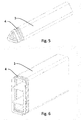
- Fig. 5 illustrates a component 1 with a triangular profile, which is prepared for use in a compound according to the invention.
- the component 1 has a circumferential groove as a molding 4.
- another at least approximately similar component 1 can be inserted, and are wrapped in the region of the molding 4 with fiber-reinforced plastic.
- Fig. 6 Similar to the Fig. 5 provides Fig. 6 a component 1 with a hollow-chamber profile that outside circumferentially also has a molding 4, for use in a compound according to the invention.
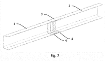
- Fig. 7 is a three-dimensional sectional view of a compound according to the invention between two components 1 and 2 with a closed square profile.
- corresponding open mold, for example U-shape, of connected components 1 can also be produced as a result of a joining method according to the invention, in particular if interconnected closed components 1 are separated after wrapping and preferably after hardening along the longitudinal axis into two approximately U-shaped halves become.
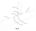
- Fig. 8 is a three-dimensional sectional view of a compound according to the invention between three components 1, 2 and 8, which together form a tee.
- each of the components 1, 2, 8 have a molding 4, in particular a groove.
- the Fig. 8 are seen as a T-connection of only two components, in which case one of the two components, which is formed by 1 and 2, a continuous profile with two formations 4 left and right of a lateral opening, and the other component, formed by 8, in the opening of the continuous profile 1, 2 is inserted.
- the entire area of the joint comprising the three formations 4 is wrapped in fiber reinforced plastic.
- the invention thus enables a simple and reliable connection between two components.
Landscapes
- Engineering & Computer Science (AREA)
- General Engineering & Computer Science (AREA)
- Mechanical Engineering (AREA)
- Chemical & Material Sciences (AREA)
- Composite Materials (AREA)
- Ocean & Marine Engineering (AREA)
- Moulding By Coating Moulds (AREA)
Abstract
Description
- Die vorliegende Erfindung betrifft eine Verbindung zwischen zwei Bauteilen, wobei die beiden Bauteile Steckabschnitte mit Profilen aufweisen, die ineinander steckbar sind und ein Verfahren zur Verbindung zweier Bauteile, wobei die beiden Bauteile Steckabschnitte mit Profilen aufweisen, die ineinander steckbar sind.
- Das einfache Ineinanderstecken von derartigen Bauteilen reicht oft nicht aus um eine stabile Verbindung herzustellen, daher ist es beispielsweise bekannt die Verbindungsbereiche zusätzlich zu kleben, zu verschweißen, zu nieten oder zu verschrauben. Insbesondere wenn eines der beiden Bauteile aus faserverstärktem Kunststoff besteht und das weitere Bauteil entweder ebenfalls aus faserverstärktem Kunststoff oder auch aus einem anderen Material hergestellt ist, wurden auch andere Verbindungsmethoden, wie die Verwendung von Inserts oder Flanschen als Verbindungselemente vorgeschlagen. Hierdurch werden jedoch separat vorgefertigte Verbindungselemente benötigt. Vor allem wenn die beiden Bauteile oder Bauteile und Verbindungselemente aus unterschiedlichen Materialien bestehen sind die genannten Verbindungen oft unzureichend, da es zu unterschiedlichem Wärmeausdehnungsverhalten und unterschiedlicher Korrosion der Bauteile kommt.
- Ein Verfahren zur Verbindung zweier Stabenden aus faserverstärktem Kunststoff ist beispielsweise aus der
DE 3508644 A1 bekannt. Bei diesem Verfahren werden die Enden der zu verbindenden Stäbe abgeschrägt und hierauf fluchtgerecht miteinander verklebt. - Die
EP 0 059 163 A1 offenbart eine Verbindung zwischen einer Hohlwelle aus faserverstärktem Kunststoff und einem Metallelement, wobei das Metallelement einen inneren Ring aufweist, der innen an der Wand der Hohlwelle anliegt und ein weiterer Metallring als äußerer Ring verwendet wird, so dass die Hohlwelle aus faserverstärktem Kunststoff zwischen den beiden Metallringen eingespannt ist. Die Verbindung wird hergestellt indem zuerst der äußere der beiden Ringe auf die Welle und dann diese zusammen mit dem äußerem Ring auf den inneren Ring thermisch aufgeschrumpft werden. - Die bekannten Verbindungen sind somit teils wenig zuverlässig und andererseits komplex und aufwändig in der Herstellung.
- Es ist eine Aufgabe der Erfindung, Verbindungen zwischen zwei Bauteilen der genannten Art in dieser Hinsicht zu verbessern und insbesondere eine effiziente und einfach herzustellende Verbindung anzugeben. Weiters ist es eine Aufgabe der Erfindung ein Verfahren zur Verbindung zweier Bauteile der genannten Art anzugeben.
- Die Lösung der Aufgabe erfolgt durch eine Verbindung zwischen zwei Bauteilen, wobei die beiden Bauteile Steckabschnitte mit Profilen aufweisen, die ineinander steckbar sind, wobei die Steckabschnitte der beiden Bauteile in einem Überlappungsbereich ineinander gesteckt sind und ein Wickelbereich der beiden Bauteile, der mindestens teilweise mit dem Überlappungsbereich zusammenfällt, mit einer Wicklung aus faserverstärktem Kunststoff umwickelt ist.
- Weiters erfolgt die Lösung der erfindungsgemäßen Aufgabe mit einem Verfahren zur Verbindung zweier Bauteile, wobei die beiden Bauteile Steckabschnitte mit Profilen aufweisen, die ineinander steckbar sind, umfassend die Verfahrensschritte
- Ineinanderstecken der beiden Steckabschnitte der beiden Bauteile in einem Überlappungsbereich
- Umwickeln eines Wickelbereiches der beiden Bauteile, der mindestens teilweise mit dem Überlappungsbereich zusammenfällt, mit einer Wicklung umfassend Fasermaterial
- Aushärten eines Matrix-Materials der Wicklung in einem Werkzeug.
- Die beiden Bauteile sind also erfindungsgemäß an deren Steckabschnitten ineinandergesteckt. Damit die Steckabschnitte ineinander steckbar sind, müssen beide Bauteile ähnliche Profile mit ähnlichen Dimensionen, beispielsweise ähnlichen Durchmessern, aufweisen, die vorzugsweise als geschlossene runde, rechteckige oder quadratische Profile ausgeführt sein können. Weiters sind die beiden Bauteile mit faserverstärktem Kunststoff umwickelt, wobei der Bereich der Wicklung zumindest teilweise in dem Abschnitt der Bauteile liegt, in dem sich die Profile auch überlappen. Bevorzugt ist zumindest der gesamte Überlappungsbereich auch umwickelt.
- Das Fasermaterial des faserverstärkten Kunststoffes kann dabei vorteilhaft aus anorganischen oder organischen Verstärkungsfasern bestehen, wie zum Beispiel aus Glasfasern, Kevlarfasern, Aramidfasern, Carbonfasern, Pflanzenfasern, Gesteinsfasern oder Gemische derselben, welche beispielsweise in Form von Fasersträngen, Fasergeweben, Fasergeflechten, Fasergestricken und/oder Faservliesen vorliegen.
- Das Matrix-Material des faserverstärkten Kunststoffes kann eine duroplastische oder auch thermoplastische Matrix sein, wie zum Beispiel Polypropylen, Polyphenylensulfid, Polyetheretherketon, Polyesterharz oder Epoxidharz oder auch eine elastomere Matrix wie Gummi oder Polyurethan.
- Weiterbildungen der Erfindung sind in den abhängigen Ansprüchen, der Beschreibung sowie den beigefügten Zeichnungen angegeben.
- Bevorzugt erstreckt sich der Wickelbereich einer erfindungsgemäßen Verbindung über den gesamten Überlappungsbereich und reicht vorzugsweise beiderseits über den Überlappungsbereich hinaus. Auf diese Weise wird eine ausreichende Wicklung mit Fasermaterial erzielt, so dass eine stabile kraftschlüssige Verbindung gewährleistet ist.
- In einer Ausführungsform können die beiden Bauteile aus unterschiedlichen Materialien bestehen.
- Beispielsweise ist die erfindungsgemäße Verbindung vorteilhaft einsetzbar wenn zumindest einer der beiden Bauteile aus faserverstärktem Kunststoff besteht. Besonders bevorzugt bestehen beide Bauteile aus faserverstärktem Kunststoff. Da sowohl eines oder beide Bauteile als auch die Wicklung aus faserverstärktem Kunststoff bestehen, werden Probleme mit unterschiedlichen Werkstoffen, wie unterschiedliche Wärmeausdehnungen und Kontaktkorrosion vermieden.
- In einer bevorzugten Ausgestaltung der Verbindung weist zumindest einer der beiden Bauteile im Wickelbereich zumindest eine Ausformung auf, so dass die Wicklung aus faserverstärktem Kunststoff formschlüssig mit der Ausformung verbunden ist. Dadurch wird zusätzlich zur kraftschlüssigen Kraftkomponente auch ein stabiler Formschluss erreicht, durch den insbesondere ein axiales Herausgleiten entlang der Achse des Ineinandersteckens der beiden Bauteile vermieden wird. Auf diese Weise wirken bevorzugt die Matrix und die Faser der Wicklung in der Ausformung Kräften entlang der Bauteilachse entgegen.
- Dabei ist die zumindest eine Ausformung bevorzugt eine in Umfangsrichtung des geschlossenen Profils des zumindest einen Bauteils umlaufende Verjüngung, Abstufung oder Nut, also insbesondere eine umlaufende Rille. Hierdurch wird ein Formschluss in Längsrichtung der Bauteile erreicht.
- Bevorzugt kann die Ausformung so ausgeführt sein, dass zusätzlich oder alternativ zum Formschluss in Längsrichtung ein Formschluss gegen Verdrehung, also quer zur Längsrichtung der Bauteile erreicht wird.
- In einer Ausführungsform umfasst eine erfindungsgemäße Verbindung einen dritten Bauteil, der einen Steckabschnitt aufweist, wobei die Steckabschnitte der drei Bauteile in einem Überlappungsbereich ineinander gesteckt sind und ein Wickelbereich der drei Bauteile, der mindestens teilweise mit dem Überlappungsbereich zusammenfällt, mit einer Wicklung aus faserverstärktem Kunststoff umwickelt ist. Durch das erfindungsgemäße Verbinden von drei Bauteilen ist es beispielsweise möglich eine stabile T-Verbindung aus drei Bauteilen aufzubauen. Dabei weisen besonders bevorzugt alle drei Bauteile zumindest je eine radiale Rille auf, die formschlüssig umwickelt wird.
- Erfindungsgemäß kann eine T-Verbindung oder X-Verbindung auch aus lediglich zwei Bauteilen aufgebaut werden. Dabei weist das erste Bauteil bevorzugt zumindest eine seitliche Öffnung auf, und ein Ende des zweiten Bauteils wird, beispielsweise im rechten Winkel, in die Öffnung des ersten Bauteils eingesteckt. Die Öffnung des ersten Bauteils und das Ende des zweiten Bauteils bildet dann die Steckabschnitte. Der Überlappungsbereich ist dadurch ausgebildet, dass das Ende des zweiten Bauteils in den ersten Bauteil hineinragt. Der erste Bauteil kann bevorzugt zu beiden Seiten der Öffnung radial umlaufende Ausformungen aufweisen, der zweite Bauteil nahe dessen eingestecktem Ende eine weitere radial umlaufende Ausformung. Die Wicklung mit faserverstärktem Kunststoff, und daher der Wickelbereich, wird dann vorteilhaft alle drei Ausformungen formschlüssig bedecken.
- Zur Herstellung einer erfindungsgemäßen Verbindung dient das erwähnte erfindungsgemäße Verfahren das zumindest folgende Schritte umfasst:
- Ineinanderstecken der beiden Steckabschnitte der beiden Bauteile in einem Überlappungsbereich
- Umwickeln eines Wickelbereiches der beiden Bauteile, der mindestens teilweise mit dem Überlappungsbereich zusammenfällt, mit einer Wicklung umfassend Fasermaterial
- Aushärten eines Matrix-Materials der Wicklung in einem Werkzeug.
- Dabei kann die Wicklung, die Fasermaterial umfasst, zum Zeitpunkt des Umwickelns bereits das Matrix-Material enthalten, also als vorimprägniertes Halbzeug (sog. Prepregs) ausgebildet sein. Dadurch ist es nicht erforderlich zu einem späteren Zeitpunkt der Wicklung Matrix-Material beizugeben.
- In einer Ausführungsform des Verfahrens zur Verbindung zweier Bauteile ist die Wicklung zum Zeitpunkt des Umwickelns ein trockenes Fasermaterial ohne Matrix-Material. Nach dem Umwickeln der Bauteile wird in diesem Fall ein Matrix-Material in das Fasermaterial eingebracht.
- Bevorzugt wird das Matrix-Material nach dem Umwickeln in einem Werkzeug in das Fasermaterial injiziert oder eingegossen.
- Die Erfindung wird im Folgenden beispielhaft unter Bezugnahme auf die Zeichnungen beschrieben.
- Fig. 1
- ist eine 3D-Dartsellung eines ersten Schrittes eines erfindungsgemäßen Verfahrens.
- Fig. 2
- ist eine 3D-Dartsellung eines zweiten Schrittes eines erfindungsgemäßen Verfahrens.
- Fig. 3
- ist eine 3D-Dartsellung eines dritten Schrittes eines erfindungsgemäßen Verfahrens.
- Fig. 4
- ist eine 3D-Dartsellung einer erfindungsgemäßen Verbindung zwischen zwei Bauteilen mit kreisförmigem Profil.
- Fig. 5
- ist eine 3D-Dartsellung eines Bauteiles mit dreieckigem Profil zur Nutzung in einer erfindungsgemäßen Verbindung.
- Fig. 6
- ist eine 3D-Dartsellung eines Bauteiles mit Hohlkammer-Profil zur Nutzung in einer erfindungsgemäßen Verbindung.
- Fig. 7
- ist eine dreidimensionale Schnittdarstellung einer erfindungsgemäßen Verbindung zwischen zwei Bauteilen mit einem Vierkant-Profil.
- Fig. 8
- ist eine dreidimensionale Schnittdarstellung einer erfindungsgemäßen Verbindung zwischen drei Bauteilen zu einem T-Stück.
- In den
Fig. 1-3 ist ein erfindungsgemäßes Verfahren zur Verbindung zweier Bauteile 1 und 2 dargestellt, wobei die beiden Bauteile 1 und 2 Steckabschnitte aufweisen, die ineinander steckbar sind. Die Bauteile können dabei eigens ausgeformte Steckabschnitte aufweisen oder auch, wie in den Figuren dargestellt, zur Gänze so ausgebildet sein, dass sie ineinander steckbar sind. -
Fig. 1 zeigt dabei den ersten Verfahrensschritt, in dem die beiden Steckabschnitte der beiden Bauteile 1 und 2 in einem Überlappungsbereich d1 ineinander gesteckt werden. Der Überlappungsbereich d1 ist in Richtung des Ineinandersteckens kleiner als der vorgesehene Wickelbereich d2 und stellt einen Teilbereich des Wickelbereichs d2 dar. An beiden Bauteilen 1 und 2 sind um die Profile der Steckabschnitte umlaufende Ausformungen 4 ausgebildet, die als Nuten mit schrägen Wänden ausgeführt sind. Die Nuten liegen bei beiden Bauteilen 1 und 2 außerhalb des Überlappungsbereiches d1, jedoch innerhalb des Wickelbereiches d2. - In
Fig. 2 ist ein weiterer Verfahrensschritt dargestellt, in dem der Wickelbereich der beiden Bauteile 1 und 2 mit einer Wicklung 3 aus Fasermaterial umwickelt ist. Die Wicklung 3 kann dabei aus bereits vorimprägnierten oder auch aus trockenen Fasern ohne Matrix-Material bestehen. Die Wicklung 3 kommt dabei auch innerhalb der Ausformungen 4 der beiden Bauteile 1 und 2 zu liegen. - Wie in
Fig. 3 dargestellt wird nach dem Aufbringen der Wicklung 3 zumindest der Verbindungsbereich der beiden Bauteile 1 und 2 in ein Werkzeug 5 eingelegt. In die Wicklung 3 kann erforderlichenfalls im Werkzeug 5 noch eine Kunststoff-Matrix injiziert werden. Der faserverstärkte Kunststoff härtet im Werkzeug 5 in bekannter Weise aus, beispielsweise auf chemischem Weg. Anschließend kann der fertiggestellte Verbund aus Bauteil 1, Bauteil 2 und Wicklung 3 aus dem Werkzeug 5 entnommen werden. -
Fig. 4 stellt erfindungsgemäß miteinander verbundene Bauteile 1 und 2 dar, die in einem Überlappungsbereich in Richtung einer gemeinsamen Längsachse der Bauteile ineinander gesteckt sind, und in einem Wickelbereich mit einer bereits ausgehärteten Wicklung 3 aus faserverstärktem Kunststoff bedeckt sind. Im Überlappungsbereich kommt es dabei zur Ausbildung einer Zone 6 mit kraftschlüssiger Verbindung zwischen den beiden Bauteilen 1 und 2 und zur Ausbildung von Zonen 7 mit formschlüssiger Verbindung zwischen den Ausnehmungen 4 der Bauteile 1 und 2 und der Wicklung 3. -
Fig. 5 stellt ein Bauteil 1 mit dreieckigem Profil dar, dass zur Nutzung in einer erfindungsgemäßen Verbindung vorbereitet ist. Dazu weist das Bauteil 1 eine umlaufende Rille als Ausformung 4 auf. In das Bauteil 1 kann beispielsweise ein weiteres zumindest annähernd gleichartiges Bauteil 1 gesteckt werden, und im Bereich des Ausformung 4 mit faserverstärktem Kunststoff umwickelt werden. - Ähnlich der
Fig. 5 stelltFig. 6 ein Bauteil 1 mit Hohlkammer-Profil dar, dass außen umlaufend ebenfalls eine Ausformung 4 aufweist, zur Nutzung in einer erfindungsgemäßen Verbindung. -
Fig. 7 ist eine dreidimensionale Schnittdarstellung einer erfindungsgemäßen Verbindung zwischen zwei Bauteilen 1 und 2 mit einem geschlossenen Vierkant-Profil. - Eine der
Fig. 7 entsprechende offene Form, beispielsweise U-Form, von verbundenen Bauteilen 1 kann jedoch auch als Ergebnis eines erfindungsgemäßen Verbindungsverfahrens hergestellt werden, insbesondere wenn miteinander verbundene geschlossene Bauteile 1 nach dem Umwickeln und bevorzugt nach dem Aushärten entlang der Längsachse in zwei annähernd U-förmige Hälften getrennt werden. -
Fig. 8 ist eine dreidimensionale Schnittdarstellung einer erfindungsgemäßen Verbindung zwischen drei Bauteilen 1, 2 und 8, die zusammen ein T-Stück bilden. Hierbei kann jedes der Bauteile 1, 2, 8 eine Ausformung 4, insbesondere eine Rille, aufweisen. Alternativ kann dieFig. 8 als T-Verbindung lediglich zweier Bauteile gesehen werden, wobei dann eines der beiden Bauteile, dass durch 1 und 2 gebildet ist, ein durchgehendes Profil mit zwei Ausformungen 4 links und rechts einer seitlichen Öffnung darstellt, und das andere Bauteil, durch 8 gebildet, in die Öffnung des durchgehenden Profils 1, 2 eingesteckt ist. Der gesamte Bereich der Verbindung, der die drei Ausformungen 4 umfasst, ist mit faserverstärktem Kunststoff umwickelt. - Die Erfindung ermöglicht somit eine einfache und zuverlässige Verbindung zwischen zwei Bauteilen.
-
- 1
- erster Bauteil
- 2
- zweiter Bauteil
- 3
- Wicklung
- 4
- Ausformung
- 5
- Werkzeug
- 6
- Zone mit kraftschlüssiger Verbindung
- 7
- Zone mit formschlüssiger Verbindung
- 8
- dritter Bauteil
- d1
- Überlappungsbereich
- d2
- Wickelbereich
Claims (11)
- Verbindung zwischen zwei Bauteilen (1, 2), wobei die beiden Bauteile (1, 2) Steckabschnitte mit Profilen aufweisen, die ineinander steckbar sind,
dadurch gekennzeichnet, dass die Steckabschnitte der beiden Bauteile (1, 2) in einem Überlappungsbereich (d1) ineinander gesteckt sind und ein Wickelbereich (d2) der beiden Bauteile (1, 2), der mindestens teilweise mit dem Überlappungsbereich (d1) zusammenfällt, mit einer Wicklung (3) aus faserverstärktem Kunststoff umwickelt ist. - Verbindung nach Anspruch 1,
dadurch gekennzeichnet, dass der Wickelbereich (d2) sich über den gesamten Überlappungsbereich (d1) erstreckt und vorzugsweise beiderseits über den Überlappungsbereich (d1) hinausreicht. - Verbindung nach Anspruch 1 oder 2,
dadurch gekennzeichnet, dass die beiden Bauteile (1, 2) aus unterschiedlichen Materialien bestehen. - Verbindung nach einem der zuvor genannten Ansprüche,
dadurch gekennzeichnet, dass zumindest einer der beiden Bauteile (1, 2), bevorzugt beide Bauteile (1, 2) aus faserverstärktem Kunststoff bestehen. - Verbindung nach einem der zuvor genannten Ansprüche,
dadurch gekennzeichnet , dass zumindest einer der beiden Bauteile (1, 2) im Wickelbereich (d2) zumindest eine Ausformung (4) aufweist, so dass die Wicklung (3) aus faserverstärktem Kunststoff formschlüssig mit der Ausformung (4) verbunden ist. - Verbindung nach Anspruch 5,
dadurch gekennzeichnet , dass die zumindest eine Ausformung (4) eine in Umfangsrichtung des geschlossenen Profils des zumindest einen Bauteils (1, 2) umlaufende Verjüngung, Abstufung, Rille oder Nut ist. - Verbindung nach einem der zuvor genannten Ansprüche,
gekennzeichnet durch, einen dritten Bauteil (8) der einen Steckabschnitt aufweist, wobei die Steckabschnitte der drei Bauteile (1, 2, 8) in einem Überlappungsbereich (d1) ineinander gesteckt sind und ein Wickelbereich (d2) der drei Bauteile (1, 2, 8), der mindestens teilweise mit dem Überlappungsbereich (d1) zusammenfällt, mit einer Wicklung (3) aus faserverstärktem Kunststoff umwickelt ist. - Verfahren zur Verbindung zweier Bauteile (1, 2), wobei die beiden Bauteile (1, 2) Steckabschnitte mit Profilen aufweisen, die ineinander steckbar sind,
gekennzeichnet durch die Verfahrensschritte- Ineinanderstecken der beiden Steckabschnitte der beiden Bauteile (1, 2) in einem Überlappungsbereich (d1)- Umwickeln eines Wickelbereiches (d2) der beiden Bauteile (1, 2), der mindestens teilweise mit dem Überlappungsbereich (d1) zusammenfällt, mit einer Wicklung (3) umfassend Fasermaterial- Aushärten eines Matrix-Materials der Wicklung (3) in einem Werkzeug (5). - Verfahren zur Verbindung zweier Bauteile (1, 2) nach Anspruch 8,
gekennzeichnet dadurch, dass die Wicklung (3) zum Zeitpunkt des Umwickelns bereits das Matrix-Material enthält, also als vorimprägniertes Halbzeug ausgebildet ist. - Verfahren zur Verbindung zweier Bauteile (1, 2) nach Anspruch 8,
gekennzeichnet dadurch, dass die Wicklung (3) zum Zeitpunkt des Umwickelns ein trockenes Fasermaterial ohne Matrix-Material ist und das nach dem Umwickeln ein Matrix-Material in das Fasermaterial eingebracht wird. - Verfahren zur Verbindung zweier Bauteile (1, 2) nach Anspruch 10,
gekennzeichnet dadurch, dass das Matrix-Material nach dem Umwickeln in einem Werkzeug (5) in das Fasermaterial injiziert oder eingegossen wird.
Priority Applications (1)
| Application Number | Priority Date | Filing Date | Title |
|---|---|---|---|
| EP12195286.5A EP2602497B1 (de) | 2011-12-05 | 2012-12-03 | Verbindung zwischen zwei Bauteilen und Verfahren zur Verbindung zweier Bauteile |
Applications Claiming Priority (2)
| Application Number | Priority Date | Filing Date | Title |
|---|---|---|---|
| EP11191964.3A EP2602496A1 (de) | 2011-12-05 | 2011-12-05 | Verbindung zwischen zwei Bauteilen und Verfahren zur Verbindung zweier Bauteile |
| EP12195286.5A EP2602497B1 (de) | 2011-12-05 | 2012-12-03 | Verbindung zwischen zwei Bauteilen und Verfahren zur Verbindung zweier Bauteile |
Publications (2)
| Publication Number | Publication Date |
|---|---|
| EP2602497A1 true EP2602497A1 (de) | 2013-06-12 |
| EP2602497B1 EP2602497B1 (de) | 2019-04-10 |
Family
ID=47227716
Family Applications (2)
| Application Number | Title | Priority Date | Filing Date |
|---|---|---|---|
| EP11191964.3A Withdrawn EP2602496A1 (de) | 2011-12-05 | 2011-12-05 | Verbindung zwischen zwei Bauteilen und Verfahren zur Verbindung zweier Bauteile |
| EP12195286.5A Not-in-force EP2602497B1 (de) | 2011-12-05 | 2012-12-03 | Verbindung zwischen zwei Bauteilen und Verfahren zur Verbindung zweier Bauteile |
Family Applications Before (1)
| Application Number | Title | Priority Date | Filing Date |
|---|---|---|---|
| EP11191964.3A Withdrawn EP2602496A1 (de) | 2011-12-05 | 2011-12-05 | Verbindung zwischen zwei Bauteilen und Verfahren zur Verbindung zweier Bauteile |
Country Status (4)
| Country | Link |
|---|---|
| US (1) | US9664228B2 (de) |
| EP (2) | EP2602496A1 (de) |
| CN (1) | CN103975168B (de) |
| WO (1) | WO2013083526A1 (de) |
Families Citing this family (11)
| Publication number | Priority date | Publication date | Assignee | Title |
|---|---|---|---|---|
| CN106015911A (zh) * | 2016-08-04 | 2016-10-12 | 杭州友凯船艇有限公司 | 一种组合件连接凹槽 |
| KR102649318B1 (ko) * | 2016-12-29 | 2024-03-20 | 삼성전자주식회사 | 상태 회로를 포함하는 메모리 장치와 그것의 동작 방법 |
| CN109591328B (zh) * | 2018-10-12 | 2021-08-06 | 江西昌河航空工业有限公司 | 一种直升机桨叶前缘配重条的预成型工艺 |
| EP3690298B1 (de) | 2019-02-01 | 2022-03-30 | Hamilton Sundstrand Corporation | Vorrichtung zur rohrverbindung |
| EP4182155B1 (de) | 2020-07-20 | 2026-03-18 | Saudi Arabian Oil Company | Vorrichtung und verfahren zum elektroschweissverbinden von verstärkten wärmehärtenden kunstharzrohrverbindungen |
| US11794418B2 (en) | 2020-07-20 | 2023-10-24 | Saudi Arabian Oil Company | Apparatus and method for threaded-welded reinforced thermosetting resin pipe joints |
| WO2022020323A1 (en) | 2020-07-20 | 2022-01-27 | Saudi Arabian Oil Company | Apparatus and method for friction welding of reinforced thermosetting resin pipe joints |
| US12055253B2 (en) | 2020-12-17 | 2024-08-06 | Saudi Arabian Oil Company | Apparatus and method for bonding tie layers on reinforced thermosetting resin laminates for use in welding thermoset composite pipe joints |
| CN114523698A (zh) * | 2022-01-17 | 2022-05-24 | 酷黑科技(北京)有限公司 | 一种密封连接方法及密封连接装置 |
| US12259075B2 (en) | 2023-01-26 | 2025-03-25 | Saudi Arabian Oil Company | Method and system for automated installation of welded reinforced thermosetting resin pipe joints |
| US12276358B2 (en) | 2023-02-03 | 2025-04-15 | Saudi Arabian Oil Company | Corrosion-free welded connection for reinforced thermoplastic pipes (RTP) |
Citations (7)
| Publication number | Priority date | Publication date | Assignee | Title |
|---|---|---|---|---|
| FR1434084A (fr) * | 1964-05-28 | 1966-04-01 | Bristol Aeroplane Plastics Ltd | Perfectionnements apportés aux joints de tubes |
| US3938285A (en) * | 1973-01-10 | 1976-02-17 | Owens-Corning Fiberglas Corporation | Manhole and method of manufacture |
| EP0059163A1 (de) | 1981-02-18 | 1982-09-01 | Ciba-Geigy Ag | Verbindung einer Kunststoff-Torsionswelle mit einem Metallelement und Verfahren zur Herstellung der Verbindung |
| US4407528A (en) * | 1981-12-14 | 1983-10-04 | Atlantic Richfield Company | High pressure insulating flange |
| DE3508644A1 (de) | 1985-03-12 | 1986-09-18 | Bayer Ag, 5090 Leverkusen | Verfahren und verbindung von profilen |
| US4792320A (en) * | 1985-09-18 | 1988-12-20 | A. O. Smith Corporation | Composite tubular structure |
| US5732743A (en) * | 1996-06-14 | 1998-03-31 | Ls Technology Inc. | Method of sealing pipes |
Family Cites Families (13)
| Publication number | Priority date | Publication date | Assignee | Title |
|---|---|---|---|---|
| US3672712A (en) * | 1969-06-20 | 1972-06-27 | Elbert Davis | Structure for connecting attachments to fiberglass rods |
| JP4846103B2 (ja) * | 2001-02-07 | 2011-12-28 | 三菱レイヨン株式会社 | 繊維強化樹脂パイプ及びこれを用いた動力伝達シャフト |
| US7427237B2 (en) * | 2002-01-03 | 2008-09-23 | Burkett Jerald S | Load sharing composite shaft |
| WO2003089145A2 (en) * | 2002-04-19 | 2003-10-30 | Bell Helicopter Textron Inc. | Composite drive shaft with captured end adapters |
| US20060272724A1 (en) * | 2005-04-26 | 2006-12-07 | Borland Robin N | System and method for pipe repair using fiber wrap and polymeric resin |
| CN200982480Y (zh) * | 2006-04-24 | 2007-11-28 | 淄博光正新型复合材料有限责任公司 | 矿用快速连接玻璃钢管及快速接头 |
| US8418337B2 (en) * | 2006-08-29 | 2013-04-16 | Conocophillips Company | Dry fiber wrapped pipe |
| US7682256B2 (en) * | 2006-09-13 | 2010-03-23 | Kop-Flex Inc. | Flange design for filament wound composite shaft |
| JP5260126B2 (ja) * | 2008-04-17 | 2013-08-14 | 富士重工業株式会社 | 口金付樹脂管 |
| US8522827B2 (en) * | 2009-10-06 | 2013-09-03 | Neptune Research, Inc. | Protective seal for pipeline assembly |
| US20140166208A1 (en) * | 2011-06-27 | 2014-06-19 | Iq Tec Switzerland Gmbh | Preforming pre-preg |
| US10760719B2 (en) * | 2011-11-28 | 2020-09-01 | Future Pipe Industries Group Limited | Fiberglass pipe jointing methods and systems |
| US9630378B2 (en) * | 2012-09-28 | 2017-04-25 | Karlsruher Institut F Ür Technologie | Device for automated connection of two components, a wound joint connection and a method of connecting two components in a joint region |
-
2011
- 2011-12-05 EP EP11191964.3A patent/EP2602496A1/de not_active Withdrawn
-
2012
- 2012-12-03 US US14/362,805 patent/US9664228B2/en not_active Expired - Fee Related
- 2012-12-03 EP EP12195286.5A patent/EP2602497B1/de not_active Not-in-force
- 2012-12-03 WO PCT/EP2012/074260 patent/WO2013083526A1/de not_active Ceased
- 2012-12-03 CN CN201280060028.3A patent/CN103975168B/zh not_active Expired - Fee Related
Patent Citations (7)
| Publication number | Priority date | Publication date | Assignee | Title |
|---|---|---|---|---|
| FR1434084A (fr) * | 1964-05-28 | 1966-04-01 | Bristol Aeroplane Plastics Ltd | Perfectionnements apportés aux joints de tubes |
| US3938285A (en) * | 1973-01-10 | 1976-02-17 | Owens-Corning Fiberglas Corporation | Manhole and method of manufacture |
| EP0059163A1 (de) | 1981-02-18 | 1982-09-01 | Ciba-Geigy Ag | Verbindung einer Kunststoff-Torsionswelle mit einem Metallelement und Verfahren zur Herstellung der Verbindung |
| US4407528A (en) * | 1981-12-14 | 1983-10-04 | Atlantic Richfield Company | High pressure insulating flange |
| DE3508644A1 (de) | 1985-03-12 | 1986-09-18 | Bayer Ag, 5090 Leverkusen | Verfahren und verbindung von profilen |
| US4792320A (en) * | 1985-09-18 | 1988-12-20 | A. O. Smith Corporation | Composite tubular structure |
| US5732743A (en) * | 1996-06-14 | 1998-03-31 | Ls Technology Inc. | Method of sealing pipes |
Also Published As
| Publication number | Publication date |
|---|---|
| EP2602497B1 (de) | 2019-04-10 |
| WO2013083526A1 (de) | 2013-06-13 |
| EP2602496A1 (de) | 2013-06-12 |
| CN103975168A (zh) | 2014-08-06 |
| US20140363220A1 (en) | 2014-12-11 |
| CN103975168B (zh) | 2017-03-22 |
| US9664228B2 (en) | 2017-05-30 |
Similar Documents
| Publication | Publication Date | Title |
|---|---|---|
| EP2602497B1 (de) | Verbindung zwischen zwei Bauteilen und Verfahren zur Verbindung zweier Bauteile | |
| EP2040354B1 (de) | Spaltrohr eines Antriebsmotors für ein Pumpenaggregat | |
| DE3426158C1 (de) | Druckbehaelter aus faserverstaerktem Kunststoff und Verfahren zu dessen Herstellung | |
| DE68912170T2 (de) | Eine Verbundstruktur aufweisender Körper für Antriebsgelenke und Verfahren zu dessen Herstellung. | |
| EP0030996A1 (de) | Antriebswelle aus faserverstärktem Kunststoff, mit verlorenem Dorn und festgewickelten Endstücken | |
| DE102013201842A1 (de) | Radstern aus zusammengesetzten Speichenelementen und dessen Anbindung an das Felgenbett | |
| WO2012062391A1 (de) | Kraftfahrzeugstrukturbauteil aus mittels eines knotenelements verbundenen halbzeug-bauteilen und herstellungsverfahren | |
| EP3368261B1 (de) | Kernsystem, verwendung des kernsystems bei der herstellung eines faserverbundbauteils sowie verfahren zur herstellung eines faserverbundbauteils | |
| EP3165430B1 (de) | Verfahren zur herstellung einer knotenstruktur mit wenigstens zwei profilbauteilen, sowie knotenstruktur und karosserie | |
| DE102009006858A1 (de) | Wälzlagerkäfig | |
| DE102016117103A1 (de) | Verfahren zur Herstellung eines Faserverbundbauteils | |
| DE69806177T2 (de) | Elastomerkupplung mit komposit-klotz | |
| DE102017222615A1 (de) | Rotor sowie Verfahren zum Herstellen eines Rotors | |
| DE102004061057A1 (de) | Kugelgelenkverbindung zwischen einem Zapfen und einem Befestigungsteil | |
| EP1494254A1 (de) | Kraftübertragungselement, Verfahren zu dessen Herstellung und Vorrichtung zur Durchführung des Verfahrens | |
| EP3832040A1 (de) | Fertigteil mit einem betonkörper | |
| EP1628059B1 (de) | Verfahren zur Herstellung von glasfaserverstärkten Kunststoffrohren beliebigen Querschnitts mit Sandwichstruktur | |
| DE102015120268A1 (de) | Rohrsanierungsverfahren | |
| DE19524903A1 (de) | Wellenförmige Kraftübertragungseinrichtung in faserverstärkte Rahmenstrukturen sowie Verfahren zu ihrer Herstellung | |
| EP0311837B1 (de) | Hohlprofil, insbesondere Rohr, aus langfaserverstärktem Kunststoff und Verfahren zur Herstellung dieses Hohlprofils | |
| DE102019202745A1 (de) | Strukturbauteil für einen Fahrgestellrahmen und Verfahren zu seiner Herstellung | |
| DE102005018064A1 (de) | Kunstsstoffbauteil mit Metalleinsatz und Verfahren zu dessen Herstellung | |
| DE102007039582A1 (de) | Rohrkupplung | |
| DE2906705A1 (de) | Verbundrohr aus verstaerktem kunststoff sowie verfahren zu seiner herstellung | |
| DE102016002759A1 (de) | Verfahren zur Hestellung eines faserverstärkten Bauteils durch Wickeln und Verfahren zum Herstellen eines Zusammenbaus aus solchen faserverstärkten Bauteilen |
Legal Events
| Date | Code | Title | Description |
|---|---|---|---|
| PUAI | Public reference made under article 153(3) epc to a published international application that has entered the european phase |
Free format text: ORIGINAL CODE: 0009012 |
|
| 17P | Request for examination filed |
Effective date: 20121203 |
|
| AK | Designated contracting states |
Kind code of ref document: A1 Designated state(s): AL AT BE BG CH CY CZ DE DK EE ES FI FR GB GR HR HU IE IS IT LI LT LU LV MC MK MT NL NO PL PT RO RS SE SI SK SM TR |
|
| AX | Request for extension of the european patent |
Extension state: BA ME |
|
| RBV | Designated contracting states (corrected) |
Designated state(s): AL AT BE BG CH CY CZ DE DK EE ES FI FR GB GR HR HU IE IS IT LI LT LU LV MC MK MT NL NO PL PT RO RS SE SI SK SM TR |
|
| STAA | Information on the status of an ep patent application or granted ep patent |
Free format text: STATUS: EXAMINATION IS IN PROGRESS |
|
| 17Q | First examination report despatched |
Effective date: 20180703 |
|
| GRAP | Despatch of communication of intention to grant a patent |
Free format text: ORIGINAL CODE: EPIDOSNIGR1 |
|
| STAA | Information on the status of an ep patent application or granted ep patent |
Free format text: STATUS: GRANT OF PATENT IS INTENDED |
|
| INTG | Intention to grant announced |
Effective date: 20181204 |
|
| GRAS | Grant fee paid |
Free format text: ORIGINAL CODE: EPIDOSNIGR3 |
|
| GRAA | (expected) grant |
Free format text: ORIGINAL CODE: 0009210 |
|
| STAA | Information on the status of an ep patent application or granted ep patent |
Free format text: STATUS: THE PATENT HAS BEEN GRANTED |
|
| AK | Designated contracting states |
Kind code of ref document: B1 Designated state(s): AL AT BE BG CH CY CZ DE DK EE ES FI FR GB GR HR HU IE IS IT LI LT LU LV MC MK MT NL NO PL PT RO RS SE SI SK SM TR |
|
| REG | Reference to a national code |
Ref country code: GB Ref legal event code: FG4D Free format text: NOT ENGLISH |
|
| REG | Reference to a national code |
Ref country code: CH Ref legal event code: EP Ref country code: AT Ref legal event code: REF Ref document number: 1119064 Country of ref document: AT Kind code of ref document: T Effective date: 20190415 |
|
| REG | Reference to a national code |
Ref country code: IE Ref legal event code: FG4D Free format text: LANGUAGE OF EP DOCUMENT: GERMAN |
|
| REG | Reference to a national code |
Ref country code: DE Ref legal event code: R096 Ref document number: 502012014581 Country of ref document: DE |
|
| REG | Reference to a national code |
Ref country code: NL Ref legal event code: MP Effective date: 20190410 |
|
| REG | Reference to a national code |
Ref country code: LT Ref legal event code: MG4D |
|
| PG25 | Lapsed in a contracting state [announced via postgrant information from national office to epo] |
Ref country code: NL Free format text: LAPSE BECAUSE OF FAILURE TO SUBMIT A TRANSLATION OF THE DESCRIPTION OR TO PAY THE FEE WITHIN THE PRESCRIBED TIME-LIMIT Effective date: 20190410 |
|
| PG25 | Lapsed in a contracting state [announced via postgrant information from national office to epo] |
Ref country code: FI Free format text: LAPSE BECAUSE OF FAILURE TO SUBMIT A TRANSLATION OF THE DESCRIPTION OR TO PAY THE FEE WITHIN THE PRESCRIBED TIME-LIMIT Effective date: 20190410 Ref country code: NO Free format text: LAPSE BECAUSE OF FAILURE TO SUBMIT A TRANSLATION OF THE DESCRIPTION OR TO PAY THE FEE WITHIN THE PRESCRIBED TIME-LIMIT Effective date: 20190710 Ref country code: HR Free format text: LAPSE BECAUSE OF FAILURE TO SUBMIT A TRANSLATION OF THE DESCRIPTION OR TO PAY THE FEE WITHIN THE PRESCRIBED TIME-LIMIT Effective date: 20190410 Ref country code: PT Free format text: LAPSE BECAUSE OF FAILURE TO SUBMIT A TRANSLATION OF THE DESCRIPTION OR TO PAY THE FEE WITHIN THE PRESCRIBED TIME-LIMIT Effective date: 20190910 Ref country code: SE Free format text: LAPSE BECAUSE OF FAILURE TO SUBMIT A TRANSLATION OF THE DESCRIPTION OR TO PAY THE FEE WITHIN THE PRESCRIBED TIME-LIMIT Effective date: 20190410 Ref country code: AL Free format text: LAPSE BECAUSE OF FAILURE TO SUBMIT A TRANSLATION OF THE DESCRIPTION OR TO PAY THE FEE WITHIN THE PRESCRIBED TIME-LIMIT Effective date: 20190410 Ref country code: ES Free format text: LAPSE BECAUSE OF FAILURE TO SUBMIT A TRANSLATION OF THE DESCRIPTION OR TO PAY THE FEE WITHIN THE PRESCRIBED TIME-LIMIT Effective date: 20190410 Ref country code: LT Free format text: LAPSE BECAUSE OF FAILURE TO SUBMIT A TRANSLATION OF THE DESCRIPTION OR TO PAY THE FEE WITHIN THE PRESCRIBED TIME-LIMIT Effective date: 20190410 |
|
| PG25 | Lapsed in a contracting state [announced via postgrant information from national office to epo] |
Ref country code: BG Free format text: LAPSE BECAUSE OF FAILURE TO SUBMIT A TRANSLATION OF THE DESCRIPTION OR TO PAY THE FEE WITHIN THE PRESCRIBED TIME-LIMIT Effective date: 20190710 Ref country code: RS Free format text: LAPSE BECAUSE OF FAILURE TO SUBMIT A TRANSLATION OF THE DESCRIPTION OR TO PAY THE FEE WITHIN THE PRESCRIBED TIME-LIMIT Effective date: 20190410 Ref country code: GR Free format text: LAPSE BECAUSE OF FAILURE TO SUBMIT A TRANSLATION OF THE DESCRIPTION OR TO PAY THE FEE WITHIN THE PRESCRIBED TIME-LIMIT Effective date: 20190711 Ref country code: LV Free format text: LAPSE BECAUSE OF FAILURE TO SUBMIT A TRANSLATION OF THE DESCRIPTION OR TO PAY THE FEE WITHIN THE PRESCRIBED TIME-LIMIT Effective date: 20190410 Ref country code: PL Free format text: LAPSE BECAUSE OF FAILURE TO SUBMIT A TRANSLATION OF THE DESCRIPTION OR TO PAY THE FEE WITHIN THE PRESCRIBED TIME-LIMIT Effective date: 20190410 |
|
| PG25 | Lapsed in a contracting state [announced via postgrant information from national office to epo] |
Ref country code: IS Free format text: LAPSE BECAUSE OF FAILURE TO SUBMIT A TRANSLATION OF THE DESCRIPTION OR TO PAY THE FEE WITHIN THE PRESCRIBED TIME-LIMIT Effective date: 20190810 |
|
| REG | Reference to a national code |
Ref country code: DE Ref legal event code: R097 Ref document number: 502012014581 Country of ref document: DE |
|
| PG25 | Lapsed in a contracting state [announced via postgrant information from national office to epo] |
Ref country code: RO Free format text: LAPSE BECAUSE OF FAILURE TO SUBMIT A TRANSLATION OF THE DESCRIPTION OR TO PAY THE FEE WITHIN THE PRESCRIBED TIME-LIMIT Effective date: 20190410 Ref country code: SK Free format text: LAPSE BECAUSE OF FAILURE TO SUBMIT A TRANSLATION OF THE DESCRIPTION OR TO PAY THE FEE WITHIN THE PRESCRIBED TIME-LIMIT Effective date: 20190410 Ref country code: EE Free format text: LAPSE BECAUSE OF FAILURE TO SUBMIT A TRANSLATION OF THE DESCRIPTION OR TO PAY THE FEE WITHIN THE PRESCRIBED TIME-LIMIT Effective date: 20190410 Ref country code: DK Free format text: LAPSE BECAUSE OF FAILURE TO SUBMIT A TRANSLATION OF THE DESCRIPTION OR TO PAY THE FEE WITHIN THE PRESCRIBED TIME-LIMIT Effective date: 20190410 Ref country code: CZ Free format text: LAPSE BECAUSE OF FAILURE TO SUBMIT A TRANSLATION OF THE DESCRIPTION OR TO PAY THE FEE WITHIN THE PRESCRIBED TIME-LIMIT Effective date: 20190410 |
|
| PGFP | Annual fee paid to national office [announced via postgrant information from national office to epo] |
Ref country code: DE Payment date: 20191210 Year of fee payment: 8 |
|
| PLBE | No opposition filed within time limit |
Free format text: ORIGINAL CODE: 0009261 |
|
| STAA | Information on the status of an ep patent application or granted ep patent |
Free format text: STATUS: NO OPPOSITION FILED WITHIN TIME LIMIT |
|
| PG25 | Lapsed in a contracting state [announced via postgrant information from national office to epo] |
Ref country code: IT Free format text: LAPSE BECAUSE OF FAILURE TO SUBMIT A TRANSLATION OF THE DESCRIPTION OR TO PAY THE FEE WITHIN THE PRESCRIBED TIME-LIMIT Effective date: 20190410 Ref country code: SM Free format text: LAPSE BECAUSE OF FAILURE TO SUBMIT A TRANSLATION OF THE DESCRIPTION OR TO PAY THE FEE WITHIN THE PRESCRIBED TIME-LIMIT Effective date: 20190410 |
|
| 26N | No opposition filed |
Effective date: 20200113 |
|
| PG25 | Lapsed in a contracting state [announced via postgrant information from national office to epo] |
Ref country code: TR Free format text: LAPSE BECAUSE OF FAILURE TO SUBMIT A TRANSLATION OF THE DESCRIPTION OR TO PAY THE FEE WITHIN THE PRESCRIBED TIME-LIMIT Effective date: 20190410 |
|
| PG25 | Lapsed in a contracting state [announced via postgrant information from national office to epo] |
Ref country code: SI Free format text: LAPSE BECAUSE OF FAILURE TO SUBMIT A TRANSLATION OF THE DESCRIPTION OR TO PAY THE FEE WITHIN THE PRESCRIBED TIME-LIMIT Effective date: 20190410 |
|
| REG | Reference to a national code |
Ref country code: CH Ref legal event code: PL |
|
| REG | Reference to a national code |
Ref country code: BE Ref legal event code: MM Effective date: 20191231 |
|
| PG25 | Lapsed in a contracting state [announced via postgrant information from national office to epo] |
Ref country code: MC Free format text: LAPSE BECAUSE OF FAILURE TO SUBMIT A TRANSLATION OF THE DESCRIPTION OR TO PAY THE FEE WITHIN THE PRESCRIBED TIME-LIMIT Effective date: 20190410 |
|
| GBPC | Gb: european patent ceased through non-payment of renewal fee |
Effective date: 20191203 |
|
| PG25 | Lapsed in a contracting state [announced via postgrant information from national office to epo] |
Ref country code: IE Free format text: LAPSE BECAUSE OF NON-PAYMENT OF DUE FEES Effective date: 20191203 Ref country code: FR Free format text: LAPSE BECAUSE OF NON-PAYMENT OF DUE FEES Effective date: 20191231 Ref country code: GB Free format text: LAPSE BECAUSE OF NON-PAYMENT OF DUE FEES Effective date: 20191203 Ref country code: LU Free format text: LAPSE BECAUSE OF NON-PAYMENT OF DUE FEES Effective date: 20191203 |
|
| PG25 | Lapsed in a contracting state [announced via postgrant information from national office to epo] |
Ref country code: CH Free format text: LAPSE BECAUSE OF NON-PAYMENT OF DUE FEES Effective date: 20191231 Ref country code: BE Free format text: LAPSE BECAUSE OF NON-PAYMENT OF DUE FEES Effective date: 20191231 Ref country code: LI Free format text: LAPSE BECAUSE OF NON-PAYMENT OF DUE FEES Effective date: 20191231 |
|
| REG | Reference to a national code |
Ref country code: AT Ref legal event code: MM01 Ref document number: 1119064 Country of ref document: AT Kind code of ref document: T Effective date: 20191203 |
|
| PG25 | Lapsed in a contracting state [announced via postgrant information from national office to epo] |
Ref country code: AT Free format text: LAPSE BECAUSE OF NON-PAYMENT OF DUE FEES Effective date: 20191203 Ref country code: CY Free format text: LAPSE BECAUSE OF FAILURE TO SUBMIT A TRANSLATION OF THE DESCRIPTION OR TO PAY THE FEE WITHIN THE PRESCRIBED TIME-LIMIT Effective date: 20190410 |
|
| REG | Reference to a national code |
Ref country code: DE Ref legal event code: R119 Ref document number: 502012014581 Country of ref document: DE |
|
| PG25 | Lapsed in a contracting state [announced via postgrant information from national office to epo] |
Ref country code: MT Free format text: LAPSE BECAUSE OF FAILURE TO SUBMIT A TRANSLATION OF THE DESCRIPTION OR TO PAY THE FEE WITHIN THE PRESCRIBED TIME-LIMIT Effective date: 20190410 Ref country code: HU Free format text: LAPSE BECAUSE OF FAILURE TO SUBMIT A TRANSLATION OF THE DESCRIPTION OR TO PAY THE FEE WITHIN THE PRESCRIBED TIME-LIMIT; INVALID AB INITIO Effective date: 20121203 |
|
| PG25 | Lapsed in a contracting state [announced via postgrant information from national office to epo] |
Ref country code: DE Free format text: LAPSE BECAUSE OF NON-PAYMENT OF DUE FEES Effective date: 20210701 |
|
| PG25 | Lapsed in a contracting state [announced via postgrant information from national office to epo] |
Ref country code: MK Free format text: LAPSE BECAUSE OF FAILURE TO SUBMIT A TRANSLATION OF THE DESCRIPTION OR TO PAY THE FEE WITHIN THE PRESCRIBED TIME-LIMIT Effective date: 20190410 |