EP2602442A1 - Cranking pad interlock - Google Patents
Cranking pad interlock Download PDFInfo
- Publication number
- EP2602442A1 EP2602442A1 EP11192026.0A EP11192026A EP2602442A1 EP 2602442 A1 EP2602442 A1 EP 2602442A1 EP 11192026 A EP11192026 A EP 11192026A EP 2602442 A1 EP2602442 A1 EP 2602442A1
- Authority
- EP
- European Patent Office
- Prior art keywords
- cranking
- shaft
- pad
- gearbox
- tool
- Prior art date
- Legal status (The legal status is an assumption and is not a legal conclusion. Google has not performed a legal analysis and makes no representation as to the accuracy of the status listed.)
- Granted
Links
Images




Classifications
-
- F—MECHANICAL ENGINEERING; LIGHTING; HEATING; WEAPONS; BLASTING
- F01—MACHINES OR ENGINES IN GENERAL; ENGINE PLANTS IN GENERAL; STEAM ENGINES
- F01D—NON-POSITIVE DISPLACEMENT MACHINES OR ENGINES, e.g. STEAM TURBINES
- F01D25/00—Component parts, details, or accessories, not provided for in, or of interest apart from, other groups
- F01D25/34—Turning or inching gear
-
- F—MECHANICAL ENGINEERING; LIGHTING; HEATING; WEAPONS; BLASTING
- F02—COMBUSTION ENGINES; HOT-GAS OR COMBUSTION-PRODUCT ENGINE PLANTS
- F02C—GAS-TURBINE PLANTS; AIR INTAKES FOR JET-PROPULSION PLANTS; CONTROLLING FUEL SUPPLY IN AIR-BREATHING JET-PROPULSION PLANTS
- F02C7/00—Features, components parts, details or accessories, not provided for in, or of interest apart form groups F02C1/00 - F02C6/00; Air intakes for jet-propulsion plants
- F02C7/32—Arrangement, mounting, or driving, of auxiliaries
-
- F—MECHANICAL ENGINEERING; LIGHTING; HEATING; WEAPONS; BLASTING
- F16—ENGINEERING ELEMENTS AND UNITS; GENERAL MEASURES FOR PRODUCING AND MAINTAINING EFFECTIVE FUNCTIONING OF MACHINES OR INSTALLATIONS; THERMAL INSULATION IN GENERAL
- F16D—COUPLINGS FOR TRANSMITTING ROTATION; CLUTCHES; BRAKES
- F16D11/00—Clutches in which the members have interengaging parts
- F16D11/14—Clutches in which the members have interengaging parts with clutching members movable only axially
-
- F—MECHANICAL ENGINEERING; LIGHTING; HEATING; WEAPONS; BLASTING
- F05—INDEXING SCHEMES RELATING TO ENGINES OR PUMPS IN VARIOUS SUBCLASSES OF CLASSES F01-F04
- F05D—INDEXING SCHEME FOR ASPECTS RELATING TO NON-POSITIVE-DISPLACEMENT MACHINES OR ENGINES, GAS-TURBINES OR JET-PROPULSION PLANTS
- F05D2230/00—Manufacture
- F05D2230/60—Assembly methods
- F05D2230/64—Assembly methods using positioning or alignment devices for aligning or centring, e.g. pins
Definitions
- the subject matter disclosed herein relates to turbomachines. More specifically, means for manually rotating an interior shaft of a turbomachine when the turbomachine is not operating.
- a cranking pad assembly for a gearbox of a turbomachine including a cranking pad shaft rotatably secured in a gearbox housing and engageable with a gearbox drivetrain when urged inwardly into the gearbox housing.
- the cranking pad shaft includes an interface for a cranking tool.
- An interlock pin retains the cranking tool at the cranking pad shaft and a disconnect spring is operably connected to the gearbox housing to bias the cranking pad shaft outwardly from the gearbox housing.
- a turbomachine system includes a turbomachine having a turbine shaft and a gearbox operably connected to the turbine shaft.
- the system includes a cranking pad assembly having a cranking pad shaft rotatably secured in a gearbox housing and engageable with a gearbox drivetrain when urged inwardly into the gearbox housing.
- the cranking pad shaft includes an interface for a cranking tool, an interlock pin to retain the cranking tool at the cranking pad shaft, and a disconnect spring operably connected to the gearbox housing to bias the cranking pad shaft outwardly from the gearbox housing.
- a method of rotating a turbine shaft includes connecting a gearbox to a turbine shaft and inserting a cranking tool into a cranking pad shaft of the gearbox.
- An interlock pin is urged radially outwardly by the insertion of the cranking tool into the cranking pad shaft and the cranking pad shaft is pushed into engagement with a drivetrain of the gearbox.
- the cranking tool is retained at the cranking pad shaft via the interlock pin.
- the cranking tool is rotated about a gearbox axis to rotate the turbine shaft. Removal of the cranking tool ensures that the cranking pad shaft is disconnected from the drivetrain.
- FIG. 1 is a schematic of an exemplary turbomachine
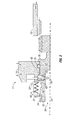
- FIG. 2 is a cross-sectional view of an exemplary embodiment of a cranking pad interlock
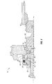
- FIG. 3 is a cross-sectional view of an exemplary embodiment of a cranking pad interlock with a cranking tool installed;
- FIG. 4 is a cross-sectional view of an exemplary embodiment of a cranking pad interlock engaging a drivetrain
- FIG. 5 is a cross-sectional view of an exemplary embodiment of a cranking pad interlock disengaging a drivetrain
- FIG. 6 is a cross-sectional view of an exemplary embodiment of a cranking pad interlock with a cranking tool withdrawing therefrom;
- FIG. 7 is a cross-sectional view of an exemplary embodiment of a cranking pad interlock with a cranking tool withdrawn.
- FIG. 1 Shown in FIG. 1 is an embodiment of a turbomachine, for example, gas turbine 10, having a turbine shaft 12.
- the turbine shaft 12 is connected to a gearbox 14 via a transmission shaft 16 such that the turbine shaft 12 can be rotated via rotation of the transmission shaft 16.
- the gearbox 14 includes a gearbox housing 18 in which the components of the gearbox 14 are located.
- the gearbox housing 18 includes a crank pad opening 20 through which a crank pad shaft 22 extends.
- the crank pad shaft 22 is rotatably secured in the gearbox 14 at a gearbox axis 24 and is sealed to the gearbox housing 18 via one or more seals 26 to prevent leakage of oil or other substances from the gearbox 14 and to prevent contamination of the gearbox 14.
- the crank pad shaft 22 is biased outwardly from the gearbox housing 18 by a disconnect spring 28.
- the disconnect spring 28 may be interactive with a disconnect clip 30 located in a clip groove 32 in an outer surface 34 of the crank pad shaft 22 to bias the crank pad shaft 22 outwardly from the gearbox housing 18.
- a shaft stop 36 at the crank pad shaft 22 limits an outward travel of the crank pad shaft 22 by an interference with the gearbox housing 18.
- the crank pad shaft 22 includes a tool cavity 38, with an interlock pin 40 extending from a shaft detent 42 in the outer surface 34 through the crank pad shaft 22 into the tool cavity 38.
- the tool cavity 38 may be a 3/8" square drive or other suitable configuration.
- a spring clip 44 is located in the shaft detent 42 radially outboard of the interlock pin 40.
- the spring clip 44 When the spring clip 44 is in the shaft detent 42, the spring clip 44 blocks axial travel of the crank pad shaft 22 by an interference between the crank pad shaft 22, the spring clip 44 and the gearbox housing 18. The travel is blocked even if a force great enough to overcome the spring force of the disconnect spring 28 is applied by, for example, pushing axially on the crank pad shaft 22.
- the tool cavity 38 is configured so that a cranking tool 46 is insertable into the tool cavity 38.
- the cranking tool 46 pushes the interlock pin 40 radially outwardly which pushes the spring clip 44 out of the shaft detent 42 and into a housing cavity 48.
- the interlock pin 40 follows the profile of the cranking tool and settles into a tool detent 54 which aligns the outside surface of the interlock pin 44 with the housing 18 bore and the spring clip 44 is aligned with the outer diameter of the cranking shaft 22.
- cranking pad shaft 22 and the cranking tool 46 may now be pushed axially inwardly into the gearbox housing 18 by overcoming the spring force of the disconnect spring 28.
- the cranking pad shaft 22 moves axially inward, the cranking pad shaft 22 engages a gearbox drivetrain 50.
- the engagement between the cranking pad shaft 22 and the gearbox drivetrain 50 may be, for example, a spline connection.
- the spring clip 44 falls radially inwardly into a locking detent 52 in the cranking pad shaft 22 to again limit the axial travel of the cranking pad shaft 22 by an interference between the cranking pad shaft 22, the spring clip 44 and the gearbox housing 18.
- the interlock pin 40 which has extended into the tool detent 54 in the cranking tool 46 locks the cranking tool 46 in engagement with the cranking pad shaft 22. Once the cranking pad shaft 22 is engaged with the drivetrain 50, the cranking tool 46 is rotated thus rotating the cranking pad shaft 22 and the drivetrain 50.
- the drivetrain 50 is connected to the turbine shaft 12 via the transmission shaft 16, so rotational energy is transferred to the turbine shaft 12, rotating it.
- cranking tool 46 is pulled axially outwardly from the crankshaft housing 18. This axially outwardly movement pulls the cranking pad shaft 22 from engagement with the drivetrain 50 because the interlock pin 40 is positioned in the tool detent 54. The axial motion forces the spring clip 44 out of the locking detent 52 and into the housing cavity 48.
- cranking tool 46 cannot be disengaged from the cranking pad shaft 22 until the cranking pad shaft 22 has traveled sufficiently far that the interlock pin 40 can be pushed radially outward into the housing cavity 48 behind the spring clip 44.
- the spring clip 44 forces the interlock pin 40 radially inward into the shaft detent 42.
- the axial position of the cranking pad shaft 22 is locked by the bias of the disconnect spring 28 and by the interference between the spring clip 44 and the gearbox housing 18 and cranking pad shaft 22.
- cranking configuration with the interlock pin 40 and spring clip 44 ensures disengagement of the cranking pad shaft 22 from the drivetrain 50 when the cranking tool 46 is removed. Further, the gearbox housing 18 remains sealed to prevent leakage from the gearbox 14 and/or contamination of the gearbox 14 without the need for a cover of the prior art. Further, this configuration removes the human element of having to reinstall a cover after removal thereby preventing leakage and contamination leading to failure of the gearbox and/or the gas turbine.
Landscapes
- Engineering & Computer Science (AREA)
- General Engineering & Computer Science (AREA)
- Mechanical Engineering (AREA)
- Chemical & Material Sciences (AREA)
- Combustion & Propulsion (AREA)
- Turbine Rotor Nozzle Sealing (AREA)
Abstract
Description
- The subject matter disclosed herein relates to turbomachines. More specifically, means for manually rotating an interior shaft of a turbomachine when the turbomachine is not operating.
- When performing maintenance and/or inspection (such as boroscope inspection) of a turbomachine, for example, a gas turbine engine for an aircraft, it is often desired to rotate the shaft of the gas turbine to provide access to interior components of the core of the gas turbine. This is typically accomplished by turning the accessory gearbox which is connected to the core. To turn the accessory gearbox, a simple cover is removed from the gearbox and a cranking tool is inserted into a cranking pad of the gearbox and the cranking tool is used to rotate the gearbox which in turn rotates the shaft of the gas turbine. Once the cranking operation is completed, the tool is removed and the cover must be replaced to seal the gearbox and gas turbine from oil leakage. If the cover is not replaced, the oil leakage can result in damage to and/or failure of the gas turbine.
- A cranking pad assembly for a gearbox of a turbomachine including a cranking pad shaft rotatably secured in a gearbox housing and engageable with a gearbox drivetrain when urged inwardly into the gearbox housing. The cranking pad shaft includes an interface for a cranking tool. An interlock pin retains the cranking tool at the cranking pad shaft and a disconnect spring is operably connected to the gearbox housing to bias the cranking pad shaft outwardly from the gearbox housing.
- A turbomachine system includes a turbomachine having a turbine shaft and a gearbox operably connected to the turbine shaft. The system includes a cranking pad assembly having a cranking pad shaft rotatably secured in a gearbox housing and engageable with a gearbox drivetrain when urged inwardly into the gearbox housing. The cranking pad shaft includes an interface for a cranking tool, an interlock pin to retain the cranking tool at the cranking pad shaft, and a disconnect spring operably connected to the gearbox housing to bias the cranking pad shaft outwardly from the gearbox housing.
- A method of rotating a turbine shaft includes connecting a gearbox to a turbine shaft and inserting a cranking tool into a cranking pad shaft of the gearbox. An interlock pin is urged radially outwardly by the insertion of the cranking tool into the cranking pad shaft and the cranking pad shaft is pushed into engagement with a drivetrain of the gearbox. The cranking tool is retained at the cranking pad shaft via the interlock pin. The cranking tool is rotated about a gearbox axis to rotate the turbine shaft. Removal of the cranking tool ensures that the cranking pad shaft is disconnected from the drivetrain.
- These and other advantages and features will become more apparent from the following description taken in conjunction with the drawings.
- The subject matter, which is regarded as the invention, is particularly pointed out and distinctly claimed in the claims at the conclusion of the specification. The foregoing and other features, and advantages of the invention are apparent from the following detailed description taken in conjunction with the accompanying drawings in which:
-
FIG. 1 is a schematic of an exemplary turbomachine; -
FIG. 2 is a cross-sectional view of an exemplary embodiment of a cranking pad interlock; -
FIG. 3 is a cross-sectional view of an exemplary embodiment of a cranking pad interlock with a cranking tool installed; -
FIG. 4 is a cross-sectional view of an exemplary embodiment of a cranking pad interlock engaging a drivetrain; -
FIG. 5 is a cross-sectional view of an exemplary embodiment of a cranking pad interlock disengaging a drivetrain; -
FIG. 6 is a cross-sectional view of an exemplary embodiment of a cranking pad interlock with a cranking tool withdrawing therefrom; and -
FIG. 7 is a cross-sectional view of an exemplary embodiment of a cranking pad interlock with a cranking tool withdrawn. - The detailed description explains embodiments of the invention, together with advantages and features, by way of example with reference to the drawings.
- Shown in
FIG. 1 is an embodiment of a turbomachine, for example,gas turbine 10, having aturbine shaft 12. Theturbine shaft 12 is connected to agearbox 14 via atransmission shaft 16 such that theturbine shaft 12 can be rotated via rotation of thetransmission shaft 16. - Referring now to
FIG. 2 , thegearbox 14 includes agearbox housing 18 in which the components of thegearbox 14 are located. Thegearbox housing 18 includes a crank pad opening 20 through which acrank pad shaft 22 extends. Thecrank pad shaft 22 is rotatably secured in thegearbox 14 at agearbox axis 24 and is sealed to thegearbox housing 18 via one ormore seals 26 to prevent leakage of oil or other substances from thegearbox 14 and to prevent contamination of thegearbox 14. - The
crank pad shaft 22 is biased outwardly from thegearbox housing 18 by adisconnect spring 28. Thedisconnect spring 28 may be interactive with adisconnect clip 30 located in aclip groove 32 in anouter surface 34 of thecrank pad shaft 22 to bias thecrank pad shaft 22 outwardly from thegearbox housing 18. A shaft stop 36 at thecrank pad shaft 22 limits an outward travel of thecrank pad shaft 22 by an interference with thegearbox housing 18. Thecrank pad shaft 22 includes atool cavity 38, with aninterlock pin 40 extending from a shaft detent 42 in theouter surface 34 through thecrank pad shaft 22 into thetool cavity 38. Thetool cavity 38 may be a 3/8" square drive or other suitable configuration. Aspring clip 44 is located in the shaft detent 42 radially outboard of theinterlock pin 40. When thespring clip 44 is in the shaft detent 42, thespring clip 44 blocks axial travel of thecrank pad shaft 22 by an interference between thecrank pad shaft 22, thespring clip 44 and the gearbox housing 18. The travel is blocked even if a force great enough to overcome the spring force of thedisconnect spring 28 is applied by, for example, pushing axially on thecrank pad shaft 22. - Referring to
FIG. 3 , thetool cavity 38 is configured so that acranking tool 46 is insertable into thetool cavity 38. When thecranking tool 46 is inserted into thetool cavity 38, thecranking tool 46 pushes theinterlock pin 40 radially outwardly which pushes thespring clip 44 out of the shaft detent 42 and into ahousing cavity 48. As the cranking tool extends into the tool cavity, theinterlock pin 40 follows the profile of the cranking tool and settles into atool detent 54 which aligns the outside surface of theinterlock pin 44 with thehousing 18 bore and thespring clip 44 is aligned with the outer diameter of the crankingshaft 22. Thecranking pad shaft 22 and thecranking tool 46 may now be pushed axially inwardly into thegearbox housing 18 by overcoming the spring force of thedisconnect spring 28. As shown inFIG. 4 , as thecranking pad shaft 22 moves axially inward, the crankingpad shaft 22 engages agearbox drivetrain 50. The engagement between thecranking pad shaft 22 and thegearbox drivetrain 50 may be, for example, a spline connection. Thespring clip 44 falls radially inwardly into a locking detent 52 in thecranking pad shaft 22 to again limit the axial travel of thecranking pad shaft 22 by an interference between thecranking pad shaft 22, thespring clip 44 and the gearbox housing 18. Theinterlock pin 40 which has extended into the tool detent 54 in thecranking tool 46 locks thecranking tool 46 in engagement with thecranking pad shaft 22. Once thecranking pad shaft 22 is engaged with thedrivetrain 50, thecranking tool 46 is rotated thus rotating thecranking pad shaft 22 and thedrivetrain 50. Thedrivetrain 50 is connected to theturbine shaft 12 via thetransmission shaft 16, so rotational energy is transferred to theturbine shaft 12, rotating it. - Referring to
FIG. 5 , to disengage thecranking pad shaft 22 from thedrivetrain 50 and remove thecranking tool 46, thecranking tool 46 is pulled axially outwardly from thecrankshaft housing 18. This axially outwardly movement pulls the crankingpad shaft 22 from engagement with thedrivetrain 50 because theinterlock pin 40 is positioned in the tool detent 54. The axial motion forces thespring clip 44 out of the locking detent 52 and into thehousing cavity 48. - Now referring to
FIG. 6 , thecranking tool 46 cannot be disengaged from thecranking pad shaft 22 until thecranking pad shaft 22 has traveled sufficiently far that theinterlock pin 40 can be pushed radially outward into thehousing cavity 48 behind thespring clip 44. When thecranking tool 46 is withdrawn from the tool cavity as shown inFIG. 7 , thespring clip 44 forces theinterlock pin 40 radially inward into the shaft detent 42. Now, the axial position of the crankingpad shaft 22 is locked by the bias of thedisconnect spring 28 and by the interference between thespring clip 44 and the gearbox housing 18 and crankingpad shaft 22. - Use of this cranking configuration with the
interlock pin 40 andspring clip 44 ensures disengagement of thecranking pad shaft 22 from thedrivetrain 50 when thecranking tool 46 is removed. Further, thegearbox housing 18 remains sealed to prevent leakage from thegearbox 14 and/or contamination of thegearbox 14 without the need for a cover of the prior art. Further, this configuration removes the human element of having to reinstall a cover after removal thereby preventing leakage and contamination leading to failure of the gearbox and/or the gas turbine. - While the invention has been described in detail in connection with only a limited number of embodiments, it should be readily understood that the invention is not limited to such disclosed embodiments. Rather, the invention can be modified to incorporate any number of variations, alterations, substitutions or equivalent arrangements not heretofore described, but which are commensurate with the scope of the invention as defined in the appended claims. Additionally, while various embodiments of the invention have been described, it is to be understood that aspects of the invention may include only some of the described embodiments. Accordingly, the invention is not to be seen as limited by the foregoing description, but is only limited by the scope of the appended claims.
Claims (14)
- A cranking pad assembly for a gearbox (14) of a turbomachine (10) comprising:a cranking pad shaft (22) rotatably secured in a gearbox housing (18) and engageable with a gearbox drivetrain (50) when urged inwardly into the gearbox housing (18), the cranking pad shaft (22) including an interface (38) for a cranking tool (46);an interlock pin (40) to retain the cranking tool (46) at the cranking pad shaft (22); anda disconnect spring (28) operably connected to the gearbox housing (18) to bias the cranking pad shaft (22) outwardly from the gearbox housing.
- The cranking pad assembly of Claim 1, further comprising a spring clip (44) disposed between the gearbox housing (18) and the cranking pad shaft (22) to limit axial movement of the cranking pad shaft relative to the gearbox housing.
- The cranking pad assembly of Claim 2, wherein the spring clip (40) is movable into a shaft detent (42) of the cranking pad shaft (22) to allow axial movement of the cranking pad shaft into engagement with the drivetrain (50).
- The cranking pad assembly of Claim 1, further comprising a seal (26) disposed between the cranking pad shaft (22) and the gearbox housing (18).
- The cranking pad assembly of any preceding Claim, wherein the interlock pin (40) is extendable through the cranking pad shaft (22) into the cranking tool (46) to retain the cranking tool.
- The cranking pad assembly of any preceding Claim, wherein the interlock pin (40) is extendable into a tooling detent (54) of the cranking tool (46).
- A turbomachine system comprising:a turbomachine (10) including a turbine shaft (12);a gearbox (14) operably connected to the turbine shaft; anda cranking pad assembly as claimed in any preceding claim.
- The turbomachine system of Claim 7, wherein rotation of the cranking pad shaft (22) when engaged with the drivetrain (50) urges rotation of the turbine shaft (12).
- The turbomachine system of Claim 7 or 8, wherein the turbomachine (10) is a gas turbine.
- A method of rotating a turbine shaft comprising:connecting a gearbox (14) to a turbine shaft (12);inserting a cranking tool (46) into a cranking pad shaft (22) of the gearbox;urging an interlock pin (40) radially outwardly by the insertion of the cranking tool (46) into the cranking pad shaft (22);pushing the cranking pad shaft (22) into engagement with a drivetrain (50) of the gearbox (18);retaining the cranking tool (46) at the cranking pad shaft (22) via the interlock pin (40); androtating the cranking tool (46) about a gearbox axis to rotate the turbine shaft (12).
- The method of Claim 10, further comprising:biasing a position of the cranking pad shaft (22) away from the drivetrain (50); andovercoming the bias by pushing the cranking pad shaft (22) into engagement with the drivetrain (50).
- The method of Claim 10 or 11, further comprising limiting a travel of the cranking pad shaft (22) along the gearbox axis via a spring clip (44) located between the cranking pad shaft (22) and a gearbox housing (18).
- The method of Claim 10, 11 or 12, further comprising pulling at the cranking tool (46) to disengage the cranking pad shaft (22) from the drivetrain (50).
- The method of Claim 10, 11, 12 or 13, further comprising retracting the interlock pin (40) into a housing cavity of the gearbox housing (18) to allow removal of the cranking tool (46) from the cranking pad shaft (22).
Priority Applications (1)
| Application Number | Priority Date | Filing Date | Title |
|---|---|---|---|
| EP20110192026 EP2602442B1 (en) | 2011-12-05 | 2011-12-05 | Cranking pad interlock |
Applications Claiming Priority (1)
| Application Number | Priority Date | Filing Date | Title |
|---|---|---|---|
| EP20110192026 EP2602442B1 (en) | 2011-12-05 | 2011-12-05 | Cranking pad interlock |
Publications (2)
| Publication Number | Publication Date |
|---|---|
| EP2602442A1 true EP2602442A1 (en) | 2013-06-12 |
| EP2602442B1 EP2602442B1 (en) | 2014-08-13 |
Family
ID=45370427
Family Applications (1)
| Application Number | Title | Priority Date | Filing Date |
|---|---|---|---|
| EP20110192026 Active EP2602442B1 (en) | 2011-12-05 | 2011-12-05 | Cranking pad interlock |
Country Status (1)
| Country | Link |
|---|---|
| EP (1) | EP2602442B1 (en) |
Cited By (1)
| Publication number | Priority date | Publication date | Assignee | Title |
|---|---|---|---|---|
| EP4015803A1 (en) * | 2020-12-17 | 2022-06-22 | Hamilton Sundstrand Corporation | Quick access engine rotator pad |
Citations (3)
| Publication number | Priority date | Publication date | Assignee | Title |
|---|---|---|---|---|
| US4437809A (en) * | 1981-12-31 | 1984-03-20 | General Electric Company | Turning gear interlock |
| EP0754838A1 (en) * | 1995-06-28 | 1997-01-22 | SOCIETE NATIONALE D'ETUDE ET DE CONSTRUCTION DE MOTEURS D'AVIATION -Snecma | Disengageable manual inching gear for a turbomachine |
| US6382909B1 (en) * | 1999-05-14 | 2002-05-07 | Dresser-Rand Company | Rotary turning apparatus |
-
2011
- 2011-12-05 EP EP20110192026 patent/EP2602442B1/en active Active
Patent Citations (3)
| Publication number | Priority date | Publication date | Assignee | Title |
|---|---|---|---|---|
| US4437809A (en) * | 1981-12-31 | 1984-03-20 | General Electric Company | Turning gear interlock |
| EP0754838A1 (en) * | 1995-06-28 | 1997-01-22 | SOCIETE NATIONALE D'ETUDE ET DE CONSTRUCTION DE MOTEURS D'AVIATION -Snecma | Disengageable manual inching gear for a turbomachine |
| US6382909B1 (en) * | 1999-05-14 | 2002-05-07 | Dresser-Rand Company | Rotary turning apparatus |
Cited By (2)
| Publication number | Priority date | Publication date | Assignee | Title |
|---|---|---|---|---|
| EP4015803A1 (en) * | 2020-12-17 | 2022-06-22 | Hamilton Sundstrand Corporation | Quick access engine rotator pad |
| US11629648B2 (en) | 2020-12-17 | 2023-04-18 | Hamilton Sundstrand Corporation | Quick access engine rotator pad |
Also Published As
| Publication number | Publication date |
|---|---|
| EP2602442B1 (en) | 2014-08-13 |
Similar Documents
| Publication | Publication Date | Title |
|---|---|---|
| US8845275B2 (en) | Cranking pad interlock | |
| JP6345778B2 (en) | Disassembly method for disengaging a drive shaft in a gear box and the gear box | |
| US8794922B2 (en) | Assembly between a compressor shaft trunnion and a bevel gear for driving an accessory gearbox of a turbomachine | |
| JP5112708B2 (en) | System for coupling engine shaft with retractable nut | |
| EP2199573B1 (en) | Generator coupling for use with gas turbine engine | |
| US8419351B2 (en) | Rotation arrangement | |
| US10436239B2 (en) | Self-locking sealing device | |
| CN104704218B (en) | Device for sealing openings in the housing wall for access to the axis of rotation | |
| FR3007070A1 (en) | ASSEMBLY FOR TURBOMACHINE | |
| US9778144B2 (en) | Systems and methods for attaching a probe to a casing of a gas turbine engine | |
| EP2602442B1 (en) | Cranking pad interlock | |
| US11668244B2 (en) | Decoupler for engine starter | |
| US7685826B2 (en) | Methods and apparatus for performing engine maintenance | |
| EP2415974B1 (en) | Sealed rotator shaft for borescopic inspection | |
| CN107531331B (en) | Turboshaft engine for an aircraft comprising an automatically activated centering element | |
| EP3059388A1 (en) | Modular components for gas turbine engines | |
| KR102102712B1 (en) | Removable Protection Device of A Transmission Seal | |
| EP3657230B1 (en) | Borescope plug system | |
| US12297872B1 (en) | Pressure retaining cap with manual interface for rotation | |
| EP4563836A1 (en) | Positive locking pistons and manual actuation of mechanical decoupler system |
Legal Events
| Date | Code | Title | Description |
|---|---|---|---|
| PUAI | Public reference made under article 153(3) epc to a published international application that has entered the european phase |
Free format text: ORIGINAL CODE: 0009012 |
|
| AK | Designated contracting states |
Kind code of ref document: A1 Designated state(s): AL AT BE BG CH CY CZ DE DK EE ES FI FR GB GR HR HU IE IS IT LI LT LU LV MC MK MT NL NO PL PT RO RS SE SI SK SM TR |
|
| AX | Request for extension of the european patent |
Extension state: BA ME |
|
| 17P | Request for examination filed |
Effective date: 20131212 |
|
| RBV | Designated contracting states (corrected) |
Designated state(s): AL AT BE BG CH CY CZ DE DK EE ES FI FR GB GR HR HU IE IS IT LI LT LU LV MC MK MT NL NO PL PT RO RS SE SI SK SM TR |
|
| GRAJ | Information related to disapproval of communication of intention to grant by the applicant or resumption of examination proceedings by the epo deleted |
Free format text: ORIGINAL CODE: EPIDOSDIGR1 |
|
| GRAP | Despatch of communication of intention to grant a patent |
Free format text: ORIGINAL CODE: EPIDOSNIGR1 |
|
| GRAP | Despatch of communication of intention to grant a patent |
Free format text: ORIGINAL CODE: EPIDOSNIGR1 |
|
| RIC1 | Information provided on ipc code assigned before grant |
Ipc: F16D 11/14 20060101ALI20140313BHEP Ipc: F02C 7/32 20060101ALI20140313BHEP Ipc: F01D 25/34 20060101AFI20140313BHEP |
|
| INTG | Intention to grant announced |
Effective date: 20140402 |
|
| INTG | Intention to grant announced |
Effective date: 20140410 |
|
| GRAS | Grant fee paid |
Free format text: ORIGINAL CODE: EPIDOSNIGR3 |
|
| GRAA | (expected) grant |
Free format text: ORIGINAL CODE: 0009210 |
|
| AK | Designated contracting states |
Kind code of ref document: B1 Designated state(s): AL AT BE BG CH CY CZ DE DK EE ES FI FR GB GR HR HU IE IS IT LI LT LU LV MC MK MT NL NO PL PT RO RS SE SI SK SM TR |
|
| REG | Reference to a national code |
Ref country code: GB Ref legal event code: FG4D |
|
| REG | Reference to a national code |
Ref country code: CH Ref legal event code: EP Ref country code: AT Ref legal event code: REF Ref document number: 682401 Country of ref document: AT Kind code of ref document: T Effective date: 20140815 |
|
| REG | Reference to a national code |
Ref country code: IE Ref legal event code: FG4D |
|
| REG | Reference to a national code |
Ref country code: DE Ref legal event code: R096 Ref document number: 602011009036 Country of ref document: DE Effective date: 20140925 |
|
| REG | Reference to a national code |
Ref country code: NL Ref legal event code: VDEP Effective date: 20140813 |
|
| REG | Reference to a national code |
Ref country code: AT Ref legal event code: MK05 Ref document number: 682401 Country of ref document: AT Kind code of ref document: T Effective date: 20140813 |
|
| REG | Reference to a national code |
Ref country code: LT Ref legal event code: MG4D |
|
| PG25 | Lapsed in a contracting state [announced via postgrant information from national office to epo] |
Ref country code: PT Free format text: LAPSE BECAUSE OF FAILURE TO SUBMIT A TRANSLATION OF THE DESCRIPTION OR TO PAY THE FEE WITHIN THE PRESCRIBED TIME-LIMIT Effective date: 20141215 Ref country code: LT Free format text: LAPSE BECAUSE OF FAILURE TO SUBMIT A TRANSLATION OF THE DESCRIPTION OR TO PAY THE FEE WITHIN THE PRESCRIBED TIME-LIMIT Effective date: 20140813 Ref country code: BG Free format text: LAPSE BECAUSE OF FAILURE TO SUBMIT A TRANSLATION OF THE DESCRIPTION OR TO PAY THE FEE WITHIN THE PRESCRIBED TIME-LIMIT Effective date: 20141113 Ref country code: FI Free format text: LAPSE BECAUSE OF FAILURE TO SUBMIT A TRANSLATION OF THE DESCRIPTION OR TO PAY THE FEE WITHIN THE PRESCRIBED TIME-LIMIT Effective date: 20140813 Ref country code: ES Free format text: LAPSE BECAUSE OF FAILURE TO SUBMIT A TRANSLATION OF THE DESCRIPTION OR TO PAY THE FEE WITHIN THE PRESCRIBED TIME-LIMIT Effective date: 20140813 Ref country code: GR Free format text: LAPSE BECAUSE OF FAILURE TO SUBMIT A TRANSLATION OF THE DESCRIPTION OR TO PAY THE FEE WITHIN THE PRESCRIBED TIME-LIMIT Effective date: 20141114 Ref country code: SE Free format text: LAPSE BECAUSE OF FAILURE TO SUBMIT A TRANSLATION OF THE DESCRIPTION OR TO PAY THE FEE WITHIN THE PRESCRIBED TIME-LIMIT Effective date: 20140813 Ref country code: NO Free format text: LAPSE BECAUSE OF FAILURE TO SUBMIT A TRANSLATION OF THE DESCRIPTION OR TO PAY THE FEE WITHIN THE PRESCRIBED TIME-LIMIT Effective date: 20141113 |
|
| PG25 | Lapsed in a contracting state [announced via postgrant information from national office to epo] |
Ref country code: IS Free format text: LAPSE BECAUSE OF FAILURE TO SUBMIT A TRANSLATION OF THE DESCRIPTION OR TO PAY THE FEE WITHIN THE PRESCRIBED TIME-LIMIT Effective date: 20141213 Ref country code: AT Free format text: LAPSE BECAUSE OF FAILURE TO SUBMIT A TRANSLATION OF THE DESCRIPTION OR TO PAY THE FEE WITHIN THE PRESCRIBED TIME-LIMIT Effective date: 20140813 Ref country code: HR Free format text: LAPSE BECAUSE OF FAILURE TO SUBMIT A TRANSLATION OF THE DESCRIPTION OR TO PAY THE FEE WITHIN THE PRESCRIBED TIME-LIMIT Effective date: 20140813 Ref country code: RS Free format text: LAPSE BECAUSE OF FAILURE TO SUBMIT A TRANSLATION OF THE DESCRIPTION OR TO PAY THE FEE WITHIN THE PRESCRIBED TIME-LIMIT Effective date: 20140813 Ref country code: LV Free format text: LAPSE BECAUSE OF FAILURE TO SUBMIT A TRANSLATION OF THE DESCRIPTION OR TO PAY THE FEE WITHIN THE PRESCRIBED TIME-LIMIT Effective date: 20140813 Ref country code: CY Free format text: LAPSE BECAUSE OF FAILURE TO SUBMIT A TRANSLATION OF THE DESCRIPTION OR TO PAY THE FEE WITHIN THE PRESCRIBED TIME-LIMIT Effective date: 20140813 |
|
| PG25 | Lapsed in a contracting state [announced via postgrant information from national office to epo] |
Ref country code: NL Free format text: LAPSE BECAUSE OF FAILURE TO SUBMIT A TRANSLATION OF THE DESCRIPTION OR TO PAY THE FEE WITHIN THE PRESCRIBED TIME-LIMIT Effective date: 20140813 |
|
| PG25 | Lapsed in a contracting state [announced via postgrant information from national office to epo] |
Ref country code: SK Free format text: LAPSE BECAUSE OF FAILURE TO SUBMIT A TRANSLATION OF THE DESCRIPTION OR TO PAY THE FEE WITHIN THE PRESCRIBED TIME-LIMIT Effective date: 20140813 Ref country code: EE Free format text: LAPSE BECAUSE OF FAILURE TO SUBMIT A TRANSLATION OF THE DESCRIPTION OR TO PAY THE FEE WITHIN THE PRESCRIBED TIME-LIMIT Effective date: 20140813 Ref country code: DK Free format text: LAPSE BECAUSE OF FAILURE TO SUBMIT A TRANSLATION OF THE DESCRIPTION OR TO PAY THE FEE WITHIN THE PRESCRIBED TIME-LIMIT Effective date: 20140813 Ref country code: RO Free format text: LAPSE BECAUSE OF FAILURE TO SUBMIT A TRANSLATION OF THE DESCRIPTION OR TO PAY THE FEE WITHIN THE PRESCRIBED TIME-LIMIT Effective date: 20140813 Ref country code: CZ Free format text: LAPSE BECAUSE OF FAILURE TO SUBMIT A TRANSLATION OF THE DESCRIPTION OR TO PAY THE FEE WITHIN THE PRESCRIBED TIME-LIMIT Effective date: 20140813 |
|
| REG | Reference to a national code |
Ref country code: DE Ref legal event code: R097 Ref document number: 602011009036 Country of ref document: DE |
|
| PG25 | Lapsed in a contracting state [announced via postgrant information from national office to epo] |
Ref country code: PL Free format text: LAPSE BECAUSE OF FAILURE TO SUBMIT A TRANSLATION OF THE DESCRIPTION OR TO PAY THE FEE WITHIN THE PRESCRIBED TIME-LIMIT Effective date: 20140813 |
|
| PLBE | No opposition filed within time limit |
Free format text: ORIGINAL CODE: 0009261 |
|
| STAA | Information on the status of an ep patent application or granted ep patent |
Free format text: STATUS: NO OPPOSITION FILED WITHIN TIME LIMIT |
|
| PG25 | Lapsed in a contracting state [announced via postgrant information from national office to epo] |
Ref country code: BE Free format text: LAPSE BECAUSE OF NON-PAYMENT OF DUE FEES Effective date: 20141231 |
|
| REG | Reference to a national code |
Ref country code: DE Ref legal event code: R119 Ref document number: 602011009036 Country of ref document: DE |
|
| 26N | No opposition filed |
Effective date: 20150515 |
|
| PG25 | Lapsed in a contracting state [announced via postgrant information from national office to epo] |
Ref country code: LU Free format text: LAPSE BECAUSE OF FAILURE TO SUBMIT A TRANSLATION OF THE DESCRIPTION OR TO PAY THE FEE WITHIN THE PRESCRIBED TIME-LIMIT Effective date: 20141205 |
|
| REG | Reference to a national code |
Ref country code: CH Ref legal event code: PL |
|
| REG | Reference to a national code |
Ref country code: IE Ref legal event code: MM4A |
|
| PG25 | Lapsed in a contracting state [announced via postgrant information from national office to epo] |
Ref country code: IE Free format text: LAPSE BECAUSE OF NON-PAYMENT OF DUE FEES Effective date: 20141205 Ref country code: DE Free format text: LAPSE BECAUSE OF NON-PAYMENT OF DUE FEES Effective date: 20150701 Ref country code: CH Free format text: LAPSE BECAUSE OF NON-PAYMENT OF DUE FEES Effective date: 20141231 Ref country code: LI Free format text: LAPSE BECAUSE OF NON-PAYMENT OF DUE FEES Effective date: 20141231 |
|
| REG | Reference to a national code |
Ref country code: FR Ref legal event code: PLFP Year of fee payment: 5 |
|
| PG25 | Lapsed in a contracting state [announced via postgrant information from national office to epo] |
Ref country code: SI Free format text: LAPSE BECAUSE OF FAILURE TO SUBMIT A TRANSLATION OF THE DESCRIPTION OR TO PAY THE FEE WITHIN THE PRESCRIBED TIME-LIMIT Effective date: 20140813 |
|
| PG25 | Lapsed in a contracting state [announced via postgrant information from national office to epo] |
Ref country code: SM Free format text: LAPSE BECAUSE OF FAILURE TO SUBMIT A TRANSLATION OF THE DESCRIPTION OR TO PAY THE FEE WITHIN THE PRESCRIBED TIME-LIMIT Effective date: 20140813 |
|
| PG25 | Lapsed in a contracting state [announced via postgrant information from national office to epo] |
Ref country code: MC Free format text: LAPSE BECAUSE OF FAILURE TO SUBMIT A TRANSLATION OF THE DESCRIPTION OR TO PAY THE FEE WITHIN THE PRESCRIBED TIME-LIMIT Effective date: 20140813 |
|
| PG25 | Lapsed in a contracting state [announced via postgrant information from national office to epo] |
Ref country code: MT Free format text: LAPSE BECAUSE OF FAILURE TO SUBMIT A TRANSLATION OF THE DESCRIPTION OR TO PAY THE FEE WITHIN THE PRESCRIBED TIME-LIMIT Effective date: 20140813 Ref country code: TR Free format text: LAPSE BECAUSE OF FAILURE TO SUBMIT A TRANSLATION OF THE DESCRIPTION OR TO PAY THE FEE WITHIN THE PRESCRIBED TIME-LIMIT Effective date: 20140813 Ref country code: BE Free format text: LAPSE BECAUSE OF FAILURE TO SUBMIT A TRANSLATION OF THE DESCRIPTION OR TO PAY THE FEE WITHIN THE PRESCRIBED TIME-LIMIT Effective date: 20140813 Ref country code: HU Free format text: LAPSE BECAUSE OF FAILURE TO SUBMIT A TRANSLATION OF THE DESCRIPTION OR TO PAY THE FEE WITHIN THE PRESCRIBED TIME-LIMIT; INVALID AB INITIO Effective date: 20111205 |
|
| GBPC | Gb: european patent ceased through non-payment of renewal fee |
Effective date: 20151205 |
|
| PG25 | Lapsed in a contracting state [announced via postgrant information from national office to epo] |
Ref country code: GB Free format text: LAPSE BECAUSE OF NON-PAYMENT OF DUE FEES Effective date: 20151205 |
|
| REG | Reference to a national code |
Ref country code: FR Ref legal event code: PLFP Year of fee payment: 6 |
|
| REG | Reference to a national code |
Ref country code: FR Ref legal event code: PLFP Year of fee payment: 7 |
|
| PG25 | Lapsed in a contracting state [announced via postgrant information from national office to epo] |
Ref country code: MK Free format text: LAPSE BECAUSE OF FAILURE TO SUBMIT A TRANSLATION OF THE DESCRIPTION OR TO PAY THE FEE WITHIN THE PRESCRIBED TIME-LIMIT Effective date: 20140813 |
|
| PG25 | Lapsed in a contracting state [announced via postgrant information from national office to epo] |
Ref country code: AL Free format text: LAPSE BECAUSE OF FAILURE TO SUBMIT A TRANSLATION OF THE DESCRIPTION OR TO PAY THE FEE WITHIN THE PRESCRIBED TIME-LIMIT Effective date: 20140813 |
|
| P01 | Opt-out of the competence of the unified patent court (upc) registered |
Effective date: 20230522 |
|
| PGFP | Annual fee paid to national office [announced via postgrant information from national office to epo] |
Ref country code: IT Payment date: 20251119 Year of fee payment: 15 |
|
| PGFP | Annual fee paid to national office [announced via postgrant information from national office to epo] |
Ref country code: FR Payment date: 20251120 Year of fee payment: 15 |