EP2602192B1 - System und Verfahren zur Landungsfeststellung - Google Patents
System und Verfahren zur Landungsfeststellung Download PDFInfo
- Publication number
- EP2602192B1 EP2602192B1 EP12185283.4A EP12185283A EP2602192B1 EP 2602192 B1 EP2602192 B1 EP 2602192B1 EP 12185283 A EP12185283 A EP 12185283A EP 2602192 B1 EP2602192 B1 EP 2602192B1
- Authority
- EP
- European Patent Office
- Prior art keywords
- wheel
- comparator
- landing
- counter
- pulse information
- Prior art date
- Legal status (The legal status is an assumption and is not a legal conclusion. Google has not performed a legal analysis and makes no representation as to the accuracy of the status listed.)
- Active
Links
Images


Classifications
-
- G—PHYSICS
- G01—MEASURING; TESTING
- G01D—MEASURING NOT SPECIALLY ADAPTED FOR A SPECIFIC VARIABLE; ARRANGEMENTS FOR MEASURING TWO OR MORE VARIABLES NOT COVERED IN A SINGLE OTHER SUBCLASS; TARIFF METERING APPARATUS; MEASURING OR TESTING NOT OTHERWISE PROVIDED FOR
- G01D5/00—Mechanical means for transferring the output of a sensing member; Means for converting the output of a sensing member to another variable where the form or nature of the sensing member does not constrain the means for converting; Transducers not specially adapted for a specific variable
- G01D5/12—Mechanical means for transferring the output of a sensing member; Means for converting the output of a sensing member to another variable where the form or nature of the sensing member does not constrain the means for converting; Transducers not specially adapted for a specific variable using electric or magnetic means
- G01D5/14—Mechanical means for transferring the output of a sensing member; Means for converting the output of a sensing member to another variable where the form or nature of the sensing member does not constrain the means for converting; Transducers not specially adapted for a specific variable using electric or magnetic means influencing the magnitude of a current or voltage
-
- B—PERFORMING OPERATIONS; TRANSPORTING
- B64—AIRCRAFT; AVIATION; COSMONAUTICS
- B64C—AEROPLANES; HELICOPTERS
- B64C25/00—Alighting gear
-
- B—PERFORMING OPERATIONS; TRANSPORTING
- B64—AIRCRAFT; AVIATION; COSMONAUTICS
- B64C—AEROPLANES; HELICOPTERS
- B64C25/00—Alighting gear
- B64C25/32—Alighting gear characterised by elements which contact the ground or similar surface
- B64C25/42—Arrangement or adaptation of brakes
- B64C25/44—Actuating mechanisms
- B64C25/46—Brake regulators for preventing skidding or aircraft somersaulting
-
- G—PHYSICS
- G01—MEASURING; TESTING
- G01P—MEASURING LINEAR OR ANGULAR SPEED, ACCELERATION, DECELERATION, OR SHOCK; INDICATING PRESENCE, ABSENCE, OR DIRECTION, OF MOVEMENT
- G01P3/00—Measuring linear or angular speed; Measuring differences of linear or angular speeds
- G01P3/42—Devices characterised by the use of electric or magnetic means
- G01P3/44—Devices characterised by the use of electric or magnetic means for measuring angular speed
-
- H—ELECTRICITY
- H03—ELECTRONIC CIRCUITRY
- H03K—PULSE TECHNIQUE
- H03K3/00—Circuits for generating electric pulses; Monostable, bistable or multistable circuits
- H03K3/02—Generators characterised by the type of circuit or by the means used for producing pulses
- H03K3/023—Generators characterised by the type of circuit or by the means used for producing pulses by the use of differential amplifiers or comparators, with internal or external positive feedback
- H03K3/0232—Monostable circuits
Definitions
- the present disclosure is related to systems and methods for landing identification for use in, for example, an aircraft.
- Systems and methods disclosed herein may be useful for use in landing identification.
- the present invention provides a method comprising: receiving pulse information over a first time period, wherein the pulse information is indicative of an angular distance travelled by a first wheel; comparing the pulse information to a threshold value; and outputting at least one of a landing likely message and a landing unlikely message based upon the comparison.
- the first wheel may be associated with an aircraft.
- the pulse information may be at least one of digital and analog.
- the method may further comprise receiving new pulse information over a second time period, wherein the new pulse information is indicative of wheel rotation, comparing the new pulse information to a threshold value, and outputting at least one of a landing likely message and a landing unlikely message based upon the comparison.
- the pulse information may comprise a voltage.
- the method may further comprise determining, in response to a high likelihood of a landing event, the angular velocity of a second wheel of the aircraft.
- the first and second wheel may be associated with a first side of the aircraft.
- the method may further comprise determining, in response to a landing likely message, the angular velocity of a third wheel of the aircraft, wherein the third wheel is associated with a second side of the aircraft.
- the present invention provides a system comprising: a timer in electrical communication with a counter, wherein the timer provides a first time period to the counter, wherein the counter stores received pulse information over the first time period, and wherein the pulse information is indicative of an angular distance travelled by a first wheel; and a comparator in electrical communication with the counter, wherein the comparator is configured to compare the received pulse information with a stored value to output at least one of a landing likely message and a landing unlikely message based upon the comparison.
- the system may further comprise a DAC that receives an analog input and provides a digital output to the counter.
- the comparator may be digital.
- the counter may be analog.
- the counter may receive an analog input in the form of a voltage, and
- the comparator may be a first wheel comparator, and the first wheel comparator may be in electrical communication with a voting comparator.
- the system may further comprise a second wheel comparator in electrical communication with the voting comparator.
- the voting comparator may output a TRUE signal in response to a TRUE signal from the first wheel comparator and a TRUE signal from the second wheel comparator.
- the first time period may be between about 50 ms and about 500 ms.
- any reference to singular includes plural embodiments, and any reference to more than one component or step may include a singular embodiment or step.
- any reference to attached, fixed, connected or the like may include permanent, removable, temporary, partial, full and/or any other possible attachment option.
- any reference to without contact (or similar phrases) may also include reduced contact or minimal contact.
- Landing identification systems that rely on wheels and/or brakes may provide redundancy and robustness to an aircraft's landing system-based landing identification system. By sourcing a landing identification system in an aircraft component apart from the landing system, there is less probability of a total system failure which, in this case, would be the failure to detect a landing.
- the output of landing identification systems may be forwarded to any aircraft component and is especially useful to aircraft components that perform various functions or change their functionality during a landing event.
- a landing identification system may be used to measure angular displacement of a wheel over time to determine wheel velocity. This value may then be compared to a known value, below which it is known that landing is unlikely. If the value is higher, a voting scheme may be used amongst one or more wheels to determine whether a landing event is occurring or if some other error condition is occurring. Multiple iterations may be used to verify a landing event and reduce the effect of transient anomalies and/or signal noise.
- An aircraft may comprise one or more types of aircraft wheel and brake assemblies.
- an aircraft may have four wheels. Two wheels may be on the left side of the plane and two wheels may be on the right side of an aircraft.
- the left side wheels may be referred to as “left outboard” (LO) and “left inboard” (LI).
- the right side wheels may be referred to as “right outboard” (RO) and “right inboard” (RI).
- Each wheel may have its own brake assembly.
- the systems and methods disclosed here may be useful in aircraft having any number of wheels.
- Aircraft wheels and brake assemblies may include one or more wheel speed sensors.
- a wheel speed sensor may sense the speed, acceleration, and/or angular displacement of a wheel. As one should understand, the knowledge of angular displacement over time allows one to calculate wheel speed (the scalar of angular velocity) and the knowledge of wheel speed over time allows one to calculate acceleration of a wheel.
- a wheel speed sensor may be of any type, such as a Hall Effect sensor or a variable reluctance sensor.
- a wheel speed sensor may output a DC voltage or an AC voltage.
- a wheel speed sensor may also output a signal at a given frequency.
- a wheel speed sensor outputs a signal at from about 1kHz to about 6kHz, and more preferably at about 3 kHz.
- the output of a wheel speed sensor may be indicative of angular displacement of a wheel. Stated another way, the output of a wheel speed sensor may correspond with a particular angular wheel position.
- Angular displacement 102 may be received by counter 104.
- Angular displacement may optionally be conditioned prior to receipt by counter 104.
- angular displacement 102 is conditioned by digital to analog convertor (DAC) 202.
- DAC digital to analog convertor
- angular displacement may be conditioned by any suitable means. Conditioning a signal may include any alteration or modification of the signal, such as converting to a square wave, digital conversion, or the like.
- Angular displacement 102 whether conditioned or unconditioned, may be referred to as "pulse information" herein.
- Counter 104 receives and stores (i.e., counts or sums) the angular displacement 102.
- Counter 104 may count any representation of angular displacement.
- Counter 104 may count peaks of a sine wave of angular displacement 102, zero crossings of a sine wave of angular displacement 102, bits of data from a digitally converted angular displacement 102, or other suitable representation of angular displacement 102.
- Timer 106 sets a period within which counter 104 counts. Timer 106 thus triggers the beginning of storage of information by counter 104 and then, at the end of the period, triggers a purge of counter 104 so that a new period may begin.
- timer 106 is a 555 timer.
- the period that timer 106 sets may be of any suitable duration. In various embodiments, the duration of the period is large enough to lessen the tendency for a "false positive" due to noise or a transient angular displacement but short enough to identify a landing event quickly.
- a period may be about 50 ms to about 500 ms, more preferably, about 100ms to about 350 ms and further preferably between 200 ms and 300 ms.
- counter 104 passes at least a portion of the information stored during the period to comparator 108.
- a counter e.g., counter 104 passes a numerical value to a comparator, where the numerical value may be, for example, a real number such as an integer.
- Counter 104 may pass information indicative of the angular displacement 102 received during the period. For example, where angular displacement 102 is digital, counter 104 may sum the digital input for passing to comparator 108. For example, where angular displacement 102 represents zero crossings, counter 104 may sum the zero crossings for passing to comparator 108. Where counter 104 outputs an analog signal, such as a voltage, counter 104 may pass a voltage to a comparator.
- Comparator 108 is a digital comparator, though analog comparators may be used in various embodiments. Comparator 108 compares the value provided by counter 104 with the threshold 110. Comparator 108 outputs a first value when the output of counter 104 is less than the threshold 110 and outputs a second value when the output of counter 104 is greater than or equal to the threshold 110. It should be noted that comparator 108 may be configured to execute any one of logical operations comprising: “greater than,” “equal to,” “less than,” “greater than or equal to,” and “less than or equal to.” Comparator 108 outputs true/false value 112. Comparator 108 is configured to output TRUE in response to the value provided by counter 104 being greater than or equal to the threshold 110 and to output FALSE in response to the value provided by counter 104 being less than threshold 110.
- Threshold 110 may be set at any suitable value. Threshold 110 may be selected in accordance with the selected period. Knowledge of an amount of angular displacement along with the time period of the angular displacement is representative of angular velocity. Thus, threshold 110 may be selected so that a comparator will output a given value in response to the angular velocity exceeding a particular value. For example, a wheel speed sensor may output a sinusoidal wave form that crosses the x axis (i.e., when the y axis equals 0) every time the wheel moves one half a degree. A counter may receive two zero crossings in a period of, for example, 200ms.
- the wheel has moved 1 degree in 200ms, and the angular velocity may be obtained by dividing the angular displacement over time.
- the threshold may then be selected to be in the range of an angular velocity associated with landing.
- various "bumps" or vibrations may cause a wheel to rotate, but not at an angular velocity or angular acceleration that also occurs during landing.
- An aircraft may be designed to land (i.e., touch wheels to the ground) at different speeds, depending on its other characteristics, its intended purposes, environmental conditions, and the like. Thus, landing may be associated with aircraft speeds of 300 miles per hour and below, and more typically aircraft speeds of less than 200 miles per hour, various conditions may necessitate landing at much lower or higher speeds.
- a landing event may be identified or it may be determined that a landing event is more likely. However, in various embodiments, a second period may elapse and an additional comparison may be performed. If another TRUE value is received, a landing event may be identified or it may be determined that a landing event is more likely. Thus, the likelihood of a landing event may be determined in response to the output of comparator 108 and/or in response to the output of a voting scheme, as described below.
- a comparator may output to a voting scheme.
- an aircraft may have four wheels, the LO, LI, RO, and RI.
- a voting scheme may be used to determine if more than one wheel is experiencing a given angular velocity and/or angular acceleration. If only one wheel is experiencing an angular velocity associated with a landing event, then a false positive may be implicated and corrective action may need to take place. If multiple wheels are experiencing an angular velocity associated with a landing event, then a landing event is more likely, and if all wheels are experiencing an angular velocity associated with a landing event, then a landing event is more likely still.
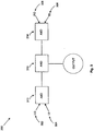
- Voting scheme 300 includes inputs LO 302, LI 304, RO 306, and RI 308.
- Each input LO 302, LI 304, RO 306, and RI 308 may be produced by components such as those shown in FIGs. 1 and 2 .
- inputs LO 302, LI 304, RO 306, and RI 308 comprise TRUE or FALSE values that are indicative of an angular velocity above a threshold amount.
- LO 302 and LO 304 are in electrical communication with AND gate 310.
- AND gate 310 is configured to output TRUE when LO 302 and LO 304 are both TRUE.
- RO 306 and RO 308 are in electrical communication with AND gate 314.
- AND gate 314 is configured to output TRUE when RO 306 and RO 308 are both TRUE.
- AND gate 310 and AND gate 314 are in electrical communication with AND gate 312.
- AND gate 312 is configured to output TRUE when both AND gate 310 and AND gate 314 are true.
- Other aircraft components may note that in response to AND gate 312 being true, a landing event is occurring and, conversely, aircraft components may note that in response to AND gate 312 being false, a landing event is not occurring.
- voting scheme 300 illustrates an embodiment where four wheels must observe a sufficient angular velocity before a landing event is identified. In various embodiments, only one or more wheels would be needed to indicate a landing event. For example, if AND gate 310 and AND gate 314 were replaced with OR gates, only one wheel on each side of the aircraft would need to observe a landing event for AND gate 310 to output TRUE. Any other implementation may be used to select which wheel and how many wheels must observe a landing event in order for the system to indicate a landing event.
- Landing detection systems may also be implemented in a circuit comprising at least one of a monostable mulivibrator, a reference voltage, MOSFET and a resistor-capacitor network. Such circuits may provide a reduced tendency for false positives due to its ability to disregard signal noise and/or transient movement of the wheel.
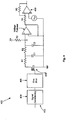
- Angular displacement signal 402 is input into signal conditioner 404.
- Signal conditioner 404 may comprise any signal conditioning step and/or no conditioning at all.
- signal conditioner 404 may condition a sinusoidal wave form into a square waveform.
- Signal conditioner 404 may rectify an AC signal into a DC signal.
- Signal conditioner 404 may output a conditioned signal.
- One shot 406 is a monostable multivibrator.
- a monostable multivibrator may be used to set a time period in response to a triggering event.
- the conditioned signal from signal conditioner 404 may be used as a triggering event.
- the rising or falling edge of the conditioned signal from signal conditioner 404 may be used as a triggering event.
- one shot 406 begins a period upon a fixed conditioned signal.
- a one shot may be in electrical communication with a wheel angular displacement circuit.
- a wheel angular displacement circuit may comprise one or more components that may evaluate the conditioned signal from signal conditioner 404 and change output state in accordance with the conditioned signal from signal conditioner 404.
- a wheel angular displacement circuit may be configured to evaluate a conditioned signal against a reference voltage, for example, and the wheel angular displacement circuit's may change output state based upon the evaluation.
- a wheel angular displacement circuit may evaluate a conditioned signal against a reference voltage and change output voltage in accordance with the evaluation.
- a wheel angular displacement circuit comprising, among other components, MOSFET 408, the illustrated voltage follower, comparator 410, and a resistor-capacitor network.
- MOSFET 408 is a metal-oxide-semiconductor field-effect transistor, though other transistors that provide the same or similar functionality are contemplated herein.
- the triggering of one shot 406 turns on MOSFET 408, which sinks current for the duration or part of the duration of the period of one shot 406.
- a resistor-capacitor network comprising R1, R2, C1 and C2.
- the resistor-capacitor network is configured to create an average voltage at node A from the pulsed voltage at the drain of the MOSFET 408.
- Other configurations of R1, R2, C1 and C2 are contemplated herein, including the addition of other components.
- the voltage follower may be in electrical communication with the resistor-capacitor network.
- the voltage follower may create a buffer to isolate the comparator 410.
- R4 and R5 are in electrical communication with the voltage follower.
- R4 is connected to the negative terminal of comparator 410 and R5 is wired in series with R4 as illustrated.
- R4 and R5 provide hysteresis functionality to comparator 410. In various embodiments, however, comparator 410 may be selected to have adequate internal hysteresis and, thus, the voltage follower and R4 and R5 may be omitted.
- the duty cycle of MOSFET 408 increases, which in turn causes the average voltage at node A to decrease.
- the duty cycle of MOSFET 408 may be sufficient to pull the input voltage to comparator 410 below the reference voltage (V ref ).
- Comparator 410 will then change outputs, indicating that the threshold of V ref has been exceeded.
- the threshold may be controlled by the pulse width of one shot 406, V ref , and the selection of V+.
- Voting schemes such voting scheme 300 of FIG. 3 , may be used in connection with embodiments such as that described in FIG. 4 .
- references to “one embodiment”, “an embodiment”, “an example embodiment”, etc., indicate that the embodiment described may include a particular feature, structure, or characteristic, but every embodiment may not necessarily include the particular feature, structure, or characteristic. Moreover, such phrases are not necessarily referring to the same embodiment.
- the terms “comprises”, “comprising”, or any other variation thereof, are intended to cover a non-exclusive inclusion, such that a process, method, article, or apparatus that comprises a list of elements does not include only those elements but may include other elements not expressly listed or inherent to such process, method, article, or apparatus.
Landscapes
- Engineering & Computer Science (AREA)
- Mechanical Engineering (AREA)
- Aviation & Aerospace Engineering (AREA)
- Physics & Mathematics (AREA)
- General Physics & Mathematics (AREA)
- Regulating Braking Force (AREA)
- Arrangements For Transmission Of Measured Signals (AREA)
Claims (15)
- Verfahren, umfassend:Empfangen von Impulsinformationen über einen ersten Zeitraum, wobei die Impulsinformationen eine von einem ersten Rad zurückgelegte Winkeldistanz angeben;Vergleichen der Impulsinformationen mit einem Schwellenwert; undAusgeben mindestens einer aus einer "Landung wahrscheinlich"-Meldung und einer "Landung unwahrscheinlich"-Meldung auf Grundlage des Vergleichs.
- Verfahren nach Anspruch 1, wobei das erste Rad mit einem Flugzeug verknüpft ist.
- Verfahren nach Anspruch 1, wobei die Impulsinformationen mindestens eines aus digital und analog sind.
- Verfahren nach Anspruch 1, weiterhin Folgendes umfassend:Empfangen neuer Impulsinformationen über einen zweiten Zeitraum, wobei die neuen Impulsinformationen Raddrehung angeben;Vergleichen der neuen Impulsinformationen mit einem Schwellenwert; undAusgeben mindestens einer aus einer "Landung wahrscheinlich"-Meldung und einer "Landung unwahrscheinlich"-Meldung auf Grundlage des Vergleichs der neuen Impulsinformationen mit dem Schwellenwert.
- Verfahren nach Anspruch 1, wobei die Impulsinformationen eine Spannung umfassen.
- Verfahren nach Anspruch 2, weiterhin umfassend das Ermitteln der Winkelgeschwindigkeit eines zweiten Rads des Flugzeugs als Reaktion auf eine "Landung wahrscheinlich"-Meldung.
- Verfahren nach Anspruch 6, wobei das erste und zweite Rad mit einer ersten Seite des Flugzeugs verknüpft sind, wobei das Verfahren weiterhin Folgendes umfasst:Ermitteln der Winkelgeschwindigkeit eines dritten Rads des Flugzeugs als Reaktion auf eine "Landung wahrscheinlich"-Meldung, wobei das dritte Rad mit einer zweiten Seite des Flugzeugs verknüpft ist.
- System (100), umfassend:einen Zeitgeber (106) in elektrischer Kommunikation mit einem Zähler (104), wobei der Zeitgeber dem Zähler einen ersten Zeitraum bereitstellt, wobei der Zähler empfangene Impulsinformationen über den ersten Zeitraum speichert, und wobei die Impulsinformationen eine von einem ersten Rad zurückgelegte Winkeldistanz angeben; undeinen Komparator (108) in elektrischer Kommunikation mit dem Zähler, wobei der Komparator dazu konfiguriert ist, die empfangenen Impulsinformationen mit einem gespeicherten Wert zu vergleichen, um mindestens eine aus einer "Landung wahrscheinlich"-Meldung und einer "Landung unwahrscheinlich"-Meldung auf Grundlage des Vergleichs auszugeben.
- System nach Anspruch 8, wobei der Zähler digital ist.
- System nach Anspruch 9, weiterhin umfassend einen DAU (202), der eine analoge Eingabe empfängt und dem Zähler eine digitale Ausgabe bereitstellt, wobei
optional:-
der Komparator digital ist. - System nach Anspruch 8, wobei der Zähler analog ist.
- System nach Anspruch 8, wobei der Zähler eine analoge Eingabe in der Form einer Spannung empfängt, und
optional:-
der Komparator analog ist. - System nach Anspruch 8, wobei der Komparator ein erster Radkomparator (310) ist, wobei der erste Radkomparator in elektrischer Kommunikation mit einem Abstimmkomparator (312) steht, und weiterhin umfassend:einen zweiten Radkomparator (314) in elektrischer Kommunikation mit dem Abstimmkomparator.
- System nach Anspruch 12, wobei der Abstimmkomparator ein WAHR-Signal als Reaktion auf ein WAHR-Signal von dem ersten Radkomparator und ein WAHR-Signal von dem zweiten Radkomparator ausgibt.
- System nach Anspruch 8, wobei der erste Zeitraum zwischen etwa 50 ms und etwa 500 ms beträgt.
Applications Claiming Priority (1)
| Application Number | Priority Date | Filing Date | Title |
|---|---|---|---|
| US13/312,073 US9688388B2 (en) | 2011-12-06 | 2011-12-06 | Systems and methods for landing identification |
Publications (2)
| Publication Number | Publication Date |
|---|---|
| EP2602192A1 EP2602192A1 (de) | 2013-06-12 |
| EP2602192B1 true EP2602192B1 (de) | 2017-05-31 |
Family
ID=47257401
Family Applications (1)
| Application Number | Title | Priority Date | Filing Date |
|---|---|---|---|
| EP12185283.4A Active EP2602192B1 (de) | 2011-12-06 | 2012-09-20 | System und Verfahren zur Landungsfeststellung |
Country Status (2)
| Country | Link |
|---|---|
| US (4) | US9688389B2 (de) |
| EP (1) | EP2602192B1 (de) |
Families Citing this family (1)
| Publication number | Priority date | Publication date | Assignee | Title |
|---|---|---|---|---|
| US9688389B2 (en) | 2011-12-06 | 2017-06-27 | Goodrich Corporation | Systems and methods for landing identification |
Family Cites Families (11)
| Publication number | Priority date | Publication date | Assignee | Title |
|---|---|---|---|---|
| NL7212387A (de) * | 1972-09-13 | 1974-03-15 | ||
| US4021647A (en) * | 1974-06-13 | 1977-05-03 | Gulf & Western Industries, Inc. | Electronic monitoring device for power press brakes and similar devices |
| US4409664A (en) * | 1979-09-27 | 1983-10-11 | Crane Co. | Digital wheel speed sensor |
| US4519559A (en) | 1979-12-26 | 1985-05-28 | Hughes Helicopters, Inc. | Landing gear energy distribution and righting system |
| US4986610A (en) | 1989-02-21 | 1991-01-22 | Aircraft Braking Systems Corporation | Brake system with brake selection means |
| JPH04197892A (ja) | 1990-11-29 | 1992-07-17 | Mitsubishi Heavy Ind Ltd | 無人機の接地タイミング検出装置 |
| US5406485A (en) * | 1993-11-09 | 1995-04-11 | Delco Electronics Corp. | Method and apparatus for detecting faulty operation of a wheel speed sensor |
| DE69634644T2 (de) * | 1995-10-11 | 2006-03-02 | The Nippon Signal Co., Ltd. | Schaltung zur Zählerprüfung |
| US5913911A (en) | 1997-02-14 | 1999-06-22 | Kuhlman Corporation | Method and apparatus for concentrating signals |
| US7946165B2 (en) | 2009-05-05 | 2011-05-24 | Goodrich Corporation | Over-speed, rough loads and hard landing detection system |
| US9688389B2 (en) * | 2011-12-06 | 2017-06-27 | Goodrich Corporation | Systems and methods for landing identification |
-
2011
- 2011-12-06 US US13/312,495 patent/US9688389B2/en active Active
- 2011-12-06 US US13/312,073 patent/US9688388B2/en active Active
-
2012
- 2012-09-20 EP EP12185283.4A patent/EP2602192B1/de active Active
-
2017
- 2017-05-23 US US15/603,116 patent/US9976875B2/en active Active
-
2018
- 2018-04-19 US US15/957,738 patent/US10648835B2/en active Active
Also Published As
| Publication number | Publication date |
|---|---|
| US20130144559A1 (en) | 2013-06-06 |
| US20170261341A1 (en) | 2017-09-14 |
| US9688389B2 (en) | 2017-06-27 |
| EP2602192A1 (de) | 2013-06-12 |
| US10648835B2 (en) | 2020-05-12 |
| US20130139590A1 (en) | 2013-06-06 |
| US9688388B2 (en) | 2017-06-27 |
| US9976875B2 (en) | 2018-05-22 |
| US20180238712A1 (en) | 2018-08-23 |
Similar Documents
| Publication | Publication Date | Title |
|---|---|---|
| US10692362B2 (en) | Systems and methods for comparing signal channels having different common mode transient immunity | |
| US8751190B2 (en) | Method for ascertaining a rotational direction of a rotating body, and wheel sensor module | |
| US11262418B2 (en) | Apparatuses and methods for sending and receiving rotation speed information | |
| JP2019533143A (ja) | 角度レゾルバ不均衡検出 | |
| US20100100345A1 (en) | System and method for identifying issues in current and voltage measurements | |
| US6502025B1 (en) | Relative steering angle sensor diagnostic for momentary signal dropout | |
| WO2015018713A1 (en) | Position sensor device to determine a position of a moving device | |
| US11079263B2 (en) | Apparatuses and methods for evaluating a signal emitted by a rotational angle sensor | |
| US10837808B2 (en) | Device and method for testing the plausibility of signals of a rotary encoder | |
| EP4067826A1 (de) | Genaue fehlerschätzung in e-motorsensoren | |
| CN106660567B (zh) | 用于提高车轮识别装置的可用性的方法和车轮识别装置 | |
| CN103532451A (zh) | 一种旋转变压器位置信号故障诊断方法 | |
| CN104483644A (zh) | 四相开关磁阻电机两只位置传感器故障诊断与定位方法 | |
| CN105141212B (zh) | 一种永磁同步电机位置信号冗余检测方法及系统 | |
| US10648835B2 (en) | Systems and methods for landing identification | |
| US10775209B2 (en) | Control circuit and method for checking the plausibility of a rotor position angle | |
| CN111102913A (zh) | 电机定子和转子间距变化的在线检测系统 | |
| CN113859307B (zh) | 车辆运行状态的检测方法、装置及车辆 | |
| Rajesh et al. | Impact of wheel speed signal processing on Antilock Brake System in heavy road vehicles | |
| CN106796268B (zh) | 用于确定电蓄能器的内阻的方法 | |
| US11567099B2 (en) | Device and method for determining a rotational frequency of a rotating roller body | |
| CN120077280A (zh) | 用于在车辆的速度测量中求取错误的脉冲信号的方法 | |
| CN114383636A (zh) | 用于传感器的功能安全的稳健信号路径合理性检查 | |
| CN107709935B (zh) | 用于为同步电机鉴定故障的控制线路和方法 | |
| KR102289443B1 (ko) | 회전 주기 측정 기능을 구비한 타이어 압력 모니터링 센서 및 이를 이용한 회전 주기 측정 방법 |
Legal Events
| Date | Code | Title | Description |
|---|---|---|---|
| PUAI | Public reference made under article 153(3) epc to a published international application that has entered the european phase |
Free format text: ORIGINAL CODE: 0009012 |
|
| 17P | Request for examination filed |
Effective date: 20120920 |
|
| AK | Designated contracting states |
Kind code of ref document: A1 Designated state(s): AL AT BE BG CH CY CZ DE DK EE ES FI FR GB GR HR HU IE IS IT LI LT LU LV MC MK MT NL NO PL PT RO RS SE SI SK SM TR |
|
| AX | Request for extension of the european patent |
Extension state: BA ME |
|
| RIC1 | Information provided on ipc code assigned before grant |
Ipc: B64D 47/00 20060101AFI20150929BHEP |
|
| 17Q | First examination report despatched |
Effective date: 20160201 |
|
| GRAP | Despatch of communication of intention to grant a patent |
Free format text: ORIGINAL CODE: EPIDOSNIGR1 |
|
| INTG | Intention to grant announced |
Effective date: 20161209 |
|
| GRAS | Grant fee paid |
Free format text: ORIGINAL CODE: EPIDOSNIGR3 |
|
| GRAA | (expected) grant |
Free format text: ORIGINAL CODE: 0009210 |
|
| AK | Designated contracting states |
Kind code of ref document: B1 Designated state(s): AL AT BE BG CH CY CZ DE DK EE ES FI FR GB GR HR HU IE IS IT LI LT LU LV MC MK MT NL NO PL PT RO RS SE SI SK SM TR |
|
| REG | Reference to a national code |
Ref country code: CH Ref legal event code: EP Ref country code: GB Ref legal event code: FG4D |
|
| REG | Reference to a national code |
Ref country code: AT Ref legal event code: REF Ref document number: 897206 Country of ref document: AT Kind code of ref document: T Effective date: 20170615 |
|
| REG | Reference to a national code |
Ref country code: IE Ref legal event code: FG4D |
|
| REG | Reference to a national code |
Ref country code: DE Ref legal event code: R096 Ref document number: 602012032906 Country of ref document: DE |
|
| REG | Reference to a national code |
Ref country code: FR Ref legal event code: PLFP Year of fee payment: 6 |
|
| REG | Reference to a national code |
Ref country code: NL Ref legal event code: MP Effective date: 20170531 |
|
| REG | Reference to a national code |
Ref country code: LT Ref legal event code: MG4D |
|
| REG | Reference to a national code |
Ref country code: AT Ref legal event code: MK05 Ref document number: 897206 Country of ref document: AT Kind code of ref document: T Effective date: 20170531 |
|
| PG25 | Lapsed in a contracting state [announced via postgrant information from national office to epo] |
Ref country code: GR Free format text: LAPSE BECAUSE OF FAILURE TO SUBMIT A TRANSLATION OF THE DESCRIPTION OR TO PAY THE FEE WITHIN THE PRESCRIBED TIME-LIMIT Effective date: 20170901 Ref country code: NO Free format text: LAPSE BECAUSE OF FAILURE TO SUBMIT A TRANSLATION OF THE DESCRIPTION OR TO PAY THE FEE WITHIN THE PRESCRIBED TIME-LIMIT Effective date: 20170831 Ref country code: HR Free format text: LAPSE BECAUSE OF FAILURE TO SUBMIT A TRANSLATION OF THE DESCRIPTION OR TO PAY THE FEE WITHIN THE PRESCRIBED TIME-LIMIT Effective date: 20170531 Ref country code: FI Free format text: LAPSE BECAUSE OF FAILURE TO SUBMIT A TRANSLATION OF THE DESCRIPTION OR TO PAY THE FEE WITHIN THE PRESCRIBED TIME-LIMIT Effective date: 20170531 Ref country code: ES Free format text: LAPSE BECAUSE OF FAILURE TO SUBMIT A TRANSLATION OF THE DESCRIPTION OR TO PAY THE FEE WITHIN THE PRESCRIBED TIME-LIMIT Effective date: 20170531 Ref country code: AT Free format text: LAPSE BECAUSE OF FAILURE TO SUBMIT A TRANSLATION OF THE DESCRIPTION OR TO PAY THE FEE WITHIN THE PRESCRIBED TIME-LIMIT Effective date: 20170531 Ref country code: LT Free format text: LAPSE BECAUSE OF FAILURE TO SUBMIT A TRANSLATION OF THE DESCRIPTION OR TO PAY THE FEE WITHIN THE PRESCRIBED TIME-LIMIT Effective date: 20170531 |
|
| PG25 | Lapsed in a contracting state [announced via postgrant information from national office to epo] |
Ref country code: SE Free format text: LAPSE BECAUSE OF FAILURE TO SUBMIT A TRANSLATION OF THE DESCRIPTION OR TO PAY THE FEE WITHIN THE PRESCRIBED TIME-LIMIT Effective date: 20170531 Ref country code: BG Free format text: LAPSE BECAUSE OF FAILURE TO SUBMIT A TRANSLATION OF THE DESCRIPTION OR TO PAY THE FEE WITHIN THE PRESCRIBED TIME-LIMIT Effective date: 20170831 Ref country code: IS Free format text: LAPSE BECAUSE OF FAILURE TO SUBMIT A TRANSLATION OF THE DESCRIPTION OR TO PAY THE FEE WITHIN THE PRESCRIBED TIME-LIMIT Effective date: 20170930 Ref country code: RS Free format text: LAPSE BECAUSE OF FAILURE TO SUBMIT A TRANSLATION OF THE DESCRIPTION OR TO PAY THE FEE WITHIN THE PRESCRIBED TIME-LIMIT Effective date: 20170531 Ref country code: LV Free format text: LAPSE BECAUSE OF FAILURE TO SUBMIT A TRANSLATION OF THE DESCRIPTION OR TO PAY THE FEE WITHIN THE PRESCRIBED TIME-LIMIT Effective date: 20170531 Ref country code: NL Free format text: LAPSE BECAUSE OF FAILURE TO SUBMIT A TRANSLATION OF THE DESCRIPTION OR TO PAY THE FEE WITHIN THE PRESCRIBED TIME-LIMIT Effective date: 20170531 |
|
| PG25 | Lapsed in a contracting state [announced via postgrant information from national office to epo] |
Ref country code: EE Free format text: LAPSE BECAUSE OF FAILURE TO SUBMIT A TRANSLATION OF THE DESCRIPTION OR TO PAY THE FEE WITHIN THE PRESCRIBED TIME-LIMIT Effective date: 20170531 Ref country code: DK Free format text: LAPSE BECAUSE OF FAILURE TO SUBMIT A TRANSLATION OF THE DESCRIPTION OR TO PAY THE FEE WITHIN THE PRESCRIBED TIME-LIMIT Effective date: 20170531 Ref country code: SK Free format text: LAPSE BECAUSE OF FAILURE TO SUBMIT A TRANSLATION OF THE DESCRIPTION OR TO PAY THE FEE WITHIN THE PRESCRIBED TIME-LIMIT Effective date: 20170531 Ref country code: RO Free format text: LAPSE BECAUSE OF FAILURE TO SUBMIT A TRANSLATION OF THE DESCRIPTION OR TO PAY THE FEE WITHIN THE PRESCRIBED TIME-LIMIT Effective date: 20170531 Ref country code: CZ Free format text: LAPSE BECAUSE OF FAILURE TO SUBMIT A TRANSLATION OF THE DESCRIPTION OR TO PAY THE FEE WITHIN THE PRESCRIBED TIME-LIMIT Effective date: 20170531 |
|
| PG25 | Lapsed in a contracting state [announced via postgrant information from national office to epo] |
Ref country code: SM Free format text: LAPSE BECAUSE OF FAILURE TO SUBMIT A TRANSLATION OF THE DESCRIPTION OR TO PAY THE FEE WITHIN THE PRESCRIBED TIME-LIMIT Effective date: 20170531 Ref country code: IT Free format text: LAPSE BECAUSE OF FAILURE TO SUBMIT A TRANSLATION OF THE DESCRIPTION OR TO PAY THE FEE WITHIN THE PRESCRIBED TIME-LIMIT Effective date: 20170531 Ref country code: PL Free format text: LAPSE BECAUSE OF FAILURE TO SUBMIT A TRANSLATION OF THE DESCRIPTION OR TO PAY THE FEE WITHIN THE PRESCRIBED TIME-LIMIT Effective date: 20170531 |
|
| REG | Reference to a national code |
Ref country code: DE Ref legal event code: R097 Ref document number: 602012032906 Country of ref document: DE |
|
| REG | Reference to a national code |
Ref country code: DE Ref legal event code: R119 Ref document number: 602012032906 Country of ref document: DE |
|
| PLBE | No opposition filed within time limit |
Free format text: ORIGINAL CODE: 0009261 |
|
| STAA | Information on the status of an ep patent application or granted ep patent |
Free format text: STATUS: NO OPPOSITION FILED WITHIN TIME LIMIT |
|
| REG | Reference to a national code |
Ref country code: CH Ref legal event code: PL |
|
| 26N | No opposition filed |
Effective date: 20180301 |
|
| PG25 | Lapsed in a contracting state [announced via postgrant information from national office to epo] |
Ref country code: MC Free format text: LAPSE BECAUSE OF FAILURE TO SUBMIT A TRANSLATION OF THE DESCRIPTION OR TO PAY THE FEE WITHIN THE PRESCRIBED TIME-LIMIT Effective date: 20170531 Ref country code: SI Free format text: LAPSE BECAUSE OF FAILURE TO SUBMIT A TRANSLATION OF THE DESCRIPTION OR TO PAY THE FEE WITHIN THE PRESCRIBED TIME-LIMIT Effective date: 20170531 |
|
| REG | Reference to a national code |
Ref country code: IE Ref legal event code: MM4A |
|
| REG | Reference to a national code |
Ref country code: BE Ref legal event code: MM Effective date: 20170930 |
|
| PG25 | Lapsed in a contracting state [announced via postgrant information from national office to epo] |
Ref country code: LU Free format text: LAPSE BECAUSE OF NON-PAYMENT OF DUE FEES Effective date: 20170920 |
|
| PG25 | Lapsed in a contracting state [announced via postgrant information from national office to epo] |
Ref country code: DE Free format text: LAPSE BECAUSE OF NON-PAYMENT OF DUE FEES Effective date: 20180404 Ref country code: LI Free format text: LAPSE BECAUSE OF NON-PAYMENT OF DUE FEES Effective date: 20170930 Ref country code: IE Free format text: LAPSE BECAUSE OF NON-PAYMENT OF DUE FEES Effective date: 20170920 Ref country code: CH Free format text: LAPSE BECAUSE OF NON-PAYMENT OF DUE FEES Effective date: 20170930 |
|
| REG | Reference to a national code |
Ref country code: FR Ref legal event code: PLFP Year of fee payment: 7 |
|
| PG25 | Lapsed in a contracting state [announced via postgrant information from national office to epo] |
Ref country code: BE Free format text: LAPSE BECAUSE OF NON-PAYMENT OF DUE FEES Effective date: 20170930 |
|
| PG25 | Lapsed in a contracting state [announced via postgrant information from national office to epo] |
Ref country code: MT Free format text: LAPSE BECAUSE OF NON-PAYMENT OF DUE FEES Effective date: 20170920 |
|
| PG25 | Lapsed in a contracting state [announced via postgrant information from national office to epo] |
Ref country code: HU Free format text: LAPSE BECAUSE OF FAILURE TO SUBMIT A TRANSLATION OF THE DESCRIPTION OR TO PAY THE FEE WITHIN THE PRESCRIBED TIME-LIMIT; INVALID AB INITIO Effective date: 20120920 |
|
| PG25 | Lapsed in a contracting state [announced via postgrant information from national office to epo] |
Ref country code: CY Free format text: LAPSE BECAUSE OF NON-PAYMENT OF DUE FEES Effective date: 20170531 |
|
| PG25 | Lapsed in a contracting state [announced via postgrant information from national office to epo] |
Ref country code: MK Free format text: LAPSE BECAUSE OF FAILURE TO SUBMIT A TRANSLATION OF THE DESCRIPTION OR TO PAY THE FEE WITHIN THE PRESCRIBED TIME-LIMIT Effective date: 20170531 |
|
| PG25 | Lapsed in a contracting state [announced via postgrant information from national office to epo] |
Ref country code: TR Free format text: LAPSE BECAUSE OF FAILURE TO SUBMIT A TRANSLATION OF THE DESCRIPTION OR TO PAY THE FEE WITHIN THE PRESCRIBED TIME-LIMIT Effective date: 20170531 |
|
| PG25 | Lapsed in a contracting state [announced via postgrant information from national office to epo] |
Ref country code: PT Free format text: LAPSE BECAUSE OF FAILURE TO SUBMIT A TRANSLATION OF THE DESCRIPTION OR TO PAY THE FEE WITHIN THE PRESCRIBED TIME-LIMIT Effective date: 20170531 |
|
| PG25 | Lapsed in a contracting state [announced via postgrant information from national office to epo] |
Ref country code: AL Free format text: LAPSE BECAUSE OF FAILURE TO SUBMIT A TRANSLATION OF THE DESCRIPTION OR TO PAY THE FEE WITHIN THE PRESCRIBED TIME-LIMIT Effective date: 20170531 |
|
| P01 | Opt-out of the competence of the unified patent court (upc) registered |
Effective date: 20230522 |
|
| PGFP | Annual fee paid to national office [announced via postgrant information from national office to epo] |
Ref country code: GB Payment date: 20250822 Year of fee payment: 14 |
|
| PGFP | Annual fee paid to national office [announced via postgrant information from national office to epo] |
Ref country code: FR Payment date: 20250821 Year of fee payment: 14 |