EP2602170A1 - Steering apparatus - Google Patents
Steering apparatus Download PDFInfo
- Publication number
- EP2602170A1 EP2602170A1 EP11794388.6A EP11794388A EP2602170A1 EP 2602170 A1 EP2602170 A1 EP 2602170A1 EP 11794388 A EP11794388 A EP 11794388A EP 2602170 A1 EP2602170 A1 EP 2602170A1
- Authority
- EP
- European Patent Office
- Prior art keywords
- vehicle body
- steering
- column
- attaching bracket
- outer column
- Prior art date
- Legal status (The legal status is an assumption and is not a legal conclusion. Google has not performed a legal analysis and makes no representation as to the accuracy of the status listed.)
- Granted
Links
Images




Classifications
-
- B—PERFORMING OPERATIONS; TRANSPORTING
- B62—LAND VEHICLES FOR TRAVELLING OTHERWISE THAN ON RAILS
- B62D—MOTOR VEHICLES; TRAILERS
- B62D1/00—Steering controls, i.e. means for initiating a change of direction of the vehicle
- B62D1/02—Steering controls, i.e. means for initiating a change of direction of the vehicle vehicle-mounted
- B62D1/16—Steering columns
- B62D1/18—Steering columns yieldable or adjustable, e.g. tiltable
- B62D1/185—Steering columns yieldable or adjustable, e.g. tiltable adjustable by axial displacement, e.g. telescopically
-
- B—PERFORMING OPERATIONS; TRANSPORTING
- B62—LAND VEHICLES FOR TRAVELLING OTHERWISE THAN ON RAILS
- B62D—MOTOR VEHICLES; TRAILERS
- B62D1/00—Steering controls, i.e. means for initiating a change of direction of the vehicle
- B62D1/02—Steering controls, i.e. means for initiating a change of direction of the vehicle vehicle-mounted
- B62D1/16—Steering columns
- B62D1/18—Steering columns yieldable or adjustable, e.g. tiltable
- B62D1/184—Mechanisms for locking columns at selected positions
-
- B—PERFORMING OPERATIONS; TRANSPORTING
- B62—LAND VEHICLES FOR TRAVELLING OTHERWISE THAN ON RAILS
- B62D—MOTOR VEHICLES; TRAILERS
- B62D1/00—Steering controls, i.e. means for initiating a change of direction of the vehicle
- B62D1/02—Steering controls, i.e. means for initiating a change of direction of the vehicle vehicle-mounted
- B62D1/16—Steering columns
- B62D1/18—Steering columns yieldable or adjustable, e.g. tiltable
- B62D1/187—Steering columns yieldable or adjustable, e.g. tiltable with tilt adjustment; with tilt and axial adjustment
Definitions
- the present invention relates to a steering device, particularly relates to a steering device of a position adjusting type which can adjust a telescopic position (a position in a front and rear direction) of a steering wheel in accordance with a physical constitution of a driver and a driving attitude thereof.
- a steering device which is referred to as a telescopic type steering device.
- a steering device for adjusting positions of both of a tilt position (a position in an up and down direction) and a telescopic position of a steering wheel there is a steering device which is referred to as a tilt telescopic type steering device.
- a fastening rod which fastens an outer column that is adjusted to a desired adjusting position to an inner column by operating an operating lever, and fastens to clamp the outer column to a side plate of a vehicle body attaching bracket. Further, when a large impact force is operated to a front side of a vehicle body in second collision, the vehicle body attaching bracket is detached from the vehicle body and is collapsed to move to the front side of the vehicle body to thereby alleviate an impact force which is exerted to a driver.
- the steering devices there is a case where when the telescopic position of the steering wheel is disposed at a vicinity of an adjusting end on the front side of the vehicle body in a state of releasing the outer column from fastening the inner column, a large force is erroneously exerted to the steering wheel toward the front side of the vehicle body. Then, a rear end in view of the vehicle body of a long groove for adjusting the telescopic position of the outer column is brought into contact with the fastening rod and pushes the fastening rod to the front side of the vehicle body.
- the fastening rod When the fastening rod is pushed to the front side of the vehicle body, the fastening rod pushes the vehicle body attaching bracket to the front side of the vehicle body, the vehicle body attaching bracket is detached from the vehicle body, and there is a concern of detaching the outer column.
- a steering device of Patent Document 1 when an outer column is fastened to an inner column, play of the inner column relative to the outer column is eliminated by pressing an outer peripheral face of the inner column by a play eliminating cam.
- the play eliminating cam is detached from the outer peripheral face of the inner column. Therefore, when a large force is exerted erroneously to the steering wheel toward a front side of a vehicle body, a large pressing force to the front side of the vehicle body is operated to a fastening rod and a vehicle body attaching bracket, and therefore, the vehicle body attaching bracket cannot be prevented from detaching from the vehicle body.
- a first aspect of the present invention is a steering device characterized in including an inner column which can be fixed to a vehicle body, an outer column which is outwardly fitted to an outer peripheral face of the inner column to be able to adjust a telescopic position, has a slit which is formed over a predetermined length in an axial direction, and axially supports pivotably a steering shaft which is mounted with a steering wheel, a vehicle body attaching bracket which can be attached to the vehicle body to be able to collapse and move to a front side of the vehicle body, a fastening rod which clamps the outer column to the vehicle body attaching bracket by fastening the vehicle body attaching bracket to an inner side in a vehicle width direction by operating an operating lever in order to clamp the outer peripheral face of the inner column and clamp the outer column to the vehicle body attaching bracket by contracting an inner peripheral face of the outer column in a diameter thereof at a desired telescopic position, a telescopic position adjusting long
- a second aspect of the present invention is the steering device according to the first aspect of the present invention, characterized in that the engaging groove is formed at a phase the same as a phase of the slit.
- a third aspect of the present invention is the steering device according to the first aspect of the present invention, characterized in that a front end in view of the vehicle body of the engaging groove and a front end in view of the vehicle body of the engaging member are brought into face contact with each other.
- a fourth aspect of the present invention is the steering device according to the first aspect of the present invention, characterized in that a length in an axial direction of the engaging groove is formed by the shortest length by which when the engaging member is engaged with and detached from the engaging groove, the engaging member does not interfere with the engaging groove.
- a fifth aspect of the present invention is the steering device according to the first aspect of the present invention, characterized in including an urging member which presses the engaging member to the engaging groove by urging the engaging member in an axial direction of the fastening rod.
- a sixth aspect of the present invention is the steering device according to the first aspect of the present invention, characterized in that a steering assisting portion which exerts a predetermined steering assisting force to the steering shaft in accordance with a torque which is applied to the steering wheel is attached to the inner column.
- the steering device of the present invention includes the inner column which can be fixed to the vehicle body, the outer column which is outwardly fitted to the outer peripheral face of the inner column to be able to adjust the telescopic position, has the slit which is formed over the predetermined length in the axial direction, and axially supports pivotably the steering shaft which is mounted with the steering wheel, the vehicle body attaching bracket which can be attached to the vehicle body to be able to collapse and move to the front side of the vehicle body, the fastening rod which clamps the outer column to the vehicle body attaching bracket by fastening the vehicle body attaching bracket to the inner side in the vehicle width direction by operating the operating lever in order to clamp the outer peripheral face of the inner column and clamp the outer column to the vehicle body attaching bracket by contracting the inner peripheral face of the outer column in the diameter at the desired telescopic position, the telescopic position adjusting long groove which is formed at the outer column, formed to prolong in the telescopic position adjusting direction, and inserted with the fastening rod, the engaging groove which
- the telescopic position of the steering wheel is disposed at a vicinity of the adjustment end on the front side of the vehicle body, if a large force is erroneously exerted to the steering wheel toward the front side of the vehicle body, a rear end in view of the vehicle body of the telescopic position adjusting long groove of the outer column is brought into contact with the fastening rod 5, and pushes the fastening rod to the front side of the vehicle body.
- the fastening rod is more or less pushed to the front side of the vehicle body, the engaging member is brought into contact with the engaging groove and pushes the inner column to the front side of the vehicle body.
- the inner column is fixed to the vehicle body, and therefore, the large force to the front side of the vehicle body which is exerted to the steering wheel is supported by the vehicle body via the inner column, and the force which is exerted to the vehicle body attaching bracket can be reduced. Therefore, the vehicle body attaching bracket can be prevented from being detached from the vehicle body. Further, when the engaging groove is formed at the phase the same as the phase of the slit, the engaging member can compactly be contained at the inner portion of the slit, and therefore, the configuration is preferable.
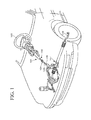
- Fig. 1 is a total perspective view showing a state of mounting a steering device 101 of the present invention to a vehicle.
- the steering device 101 axially supports a steering shaft 102 pivotably.
- the steering shaft 102 is mounted with a steering wheel 103 at an upper end thereof (on a rear side of a vehicle body), and a lower end (on a front side of the vehicle body) of the steering shaft 102 is connected with an intermediate shaft 105 via a universal joint 104.
- the intermediate shaft 105 is connected with a universal joint 106 at a lower end thereof, and the universal joint 106 is connected with a steering gear 107 configured by a rack and pinion mechanism or the like.
- Fig. 2 is a perspective view of an essential portion viewing the steering device 101 of the embodiment of the present invention from a rear side of the vehicle body.
- Fig. 3 is a vertical sectional view of a surrounding of a vehicle bodymounting bracket of Fig. 2
- Fig. 4 is a bottom view of Fig. 3
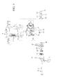
- Fig. 5 is a disassembled perspective view viewing Fig. 3 from a rear side of the vehicle body.
- Fig. 6 is an enlarged perspective view of the vehicle body attaching bracket of Fig. 3
- Fig. 7 is an enlarged disassembled perspective view of an outer column and a clamping device of Fig. 3 .
- FIG. 8 is an enlarged vertical sectional view showing a state of clamping the outer column to the vehicle body attaching bracket by operating an operating lever.
- Fig. 9 is an enlarged vertical sectional view showing a state of unclamping the outer column from the vehicle body attaching bracket by operating the operating lever.
- the steering device 101 of the embodiment of the present invention is configured by the vehicle body attaching bracket 2, an inner column (lower column) 3, a steering assisting portion 31 (electrically assisting mechanism), an outer column (upper column) 4 and the like.
- a right end of the steering assisting portion (electric assisting mechanism) 31 is fixed to a front side of the vehicle body (left side of Fig. 2 ) of the inner column 3 by press fitting.
- the steering assisting portion 31 is configured by an electric motor 311, a reduction gearbox portion 312, an output shaft 313 and the like.
- a bracket 314 integrally formed with a front end in view of the vehicle body of the steering assisting portion 31 is supported by a vehicle body, not illustrated, to be able to adjust a tilt position via a tilt center axis, not illustrated.
- an inner peripheral face 45 of the outer column 4 is outwardly fitted to an outer peripheral face 32 of the inner column 3 to be able to adjust a telescopic position (slidably move in parallel with a center axis line of the inner column 3).
- An upper steering shaft 102A is axially supported pivotably by the outer column 4, and the steering wheel 103 (refer to Fig. 1 ) is fixed to an end portion on a rear side in view of the vehicle body (right side of Fig. 2 ) of the upper steering shaft 102A.
- a slit 47 penetrating from an outer peripheral face 46 to the inner peripheral face 45 of the outer column 4 is formed on a lower side in view of the vehicle body of the outer column 4.
- the slit 47 has a shape in which both of a front end side in view of the vehicle body and a rear end side in view of the vehicle body of the outer column 4 are closed.
- a lower steering shaft 102B is axially supported pivotably by the inner column 3, and the lower steering shaft 102B is fitted to the upper steering shaft 102A by a spline. Therefore, rotation of the upper steering shaft 102A is transmitted to the lower steering shaft 102B regardless of a telescopic position of the outer column 4.
- the steering assisting portion 31 detects a torque operated to the lower steering shaft 102B, and rotates the output shaft 313 by a necessary steering assisting force by driving the electric motor 311. Rotation of the output shaft 313 is transmitted to the steering gear 107 by way of the universal joint 104, the intermediate shaft 105, and the universal joint 106, and the steering angle of the wheel can be changed.
- a front side in view of the vehicle body (left sides of Fig. 2 , Fig. 3 ) of the outer column 4 is attached with the vehicle body attaching bracket 2 which sandwiches the outer column 4 from both left and right sides in a vehicle width direction.
- the vehicle body attaching bracket 2 includes an upper plate 23 which is formed substantially horizontally in the vehicle width direction, and a pair of left and right side plates 24 and 25 which are extended to a lower side of the vehicle body from the upper plate 23 and sandwiches the outer column 4 from both left and right sides in the vehicle width direction.
- the upper plate 23 is formed with notched grooves (which are formed by opening a rear side in view of the vehicle body of the upper plate 23) 21, 21 and the upper plate 23 is mounted to the vehicle body via capsules 22 and an impact absorbing plate (refer to Fig. 6 ) 28 fitted to the notched grooves 21 and 21.
- the vehicle body attaching bracket 2 and the outer column 4 when a driver is impacted to the steering wheel 103 in second collision and a large impact force is operated thereto, the vehicle body attaching bracket 2 is detached from the capsules 22 to the front side of the vehicle body, and is collapsed to move to the front side of the vehicle body by being guided by the inner column 3, and the impact absorbing plate 28 is plastically deformed and absorbs an impact energy in collision.
- the front side in view of the vehicle body of the outer column 4 is integrally formed with a pair of clamp members 41 and 42 by being protruded to a lower side in view of the vehicle body of the outer column 4.
- the clamp members 41 and 42 are formed with long grooves 43 and 44 for adjusting a telescopic position which are extended to prolong in an axis center direction of the outer column 4.
- the side plates 24 and 25 of the vehicle body attaching bracket 2 are formed with tilt adjusting long grooves 26 and 27.
- the tilt adjusting long grooves 26 and 27 are formed in a circular arc shape centering on a tilt center axis.
- Outer side faces 411 and 421 of the clamp members 41 and 42 are slidably brought into contact with inner side faces 242 and 252 of the side plates 24 and 25 of the vehicle body attaching bracket 2.
- a fastening rod 5 in a shape of a round bar is inserted from left sides of Fig. 5 and Fig. 7 by passing the tilt adjusting long grooves 26 and 27 and the telescopic position adjusting long grooves 43 and 44.
- An operating lever 61, a movable cam 62, a fixed cam 63, a movable tilt lock gear 65, and a tilt spacer 66 are outwardly fitted to a left end side of the fastening rod 5 successively from a left side, and passes through the tilt adjusting long groove 27 and the telescopic position adjusting long groove 44.
- a spring (coil spring) 67 and an engaging member 68 inserted between inner side faces 412 and 422 of the clamp members 41 and 42 are outwardly fitted to the fastening rod 5, and a right end of the fastening rod 5 is passed through the telescopic position adjusting long groove 43 and the tilt adjusting long groove 26.
- a tilt spacer 69, a cylindrical spacer 70, a washer 71, and a thrust bearing 72 are outwardly fitted to a right end side of the fastening rod 5 successively from a left side, and a calking nut 73 is calked to be fixed to the right end of the fastening rod 5.
- a lower side in view of the vehicle body of the inner column 3 is formed with an engaging groove 34 penetrating from the outer peripheral face 32 to an inner peripheral face 33 of the inner column 3.
- the engaging groove 34 is formed at a phase position the same as a phase position of the slit 47 of the outer column 4.
- the engaging member 68 in a state of clamping the outer column 4 to the vehicle body attaching bracket 2, the engaging member 68 is rotated in the counterclockwise direction along with the fastening rod 5, and an engaging protrusion 681 of the engaging member 68 is detached from the engaging groove 34.
- the engaging groove 34 is formed at the phase position the same as the phase position of the slit 47, and therefore, the engaging member 68 can compactly be contained to an inner portion of the slit 47.
- a length in an axial direction of the engaging groove 34 is formed by the shortest length to a degree by which when the engaging protrusion 681 of the engaging member 68 is engaged with and detached from the engaging groove 34, the engaging protrusion 681 does not interfere with a front end in view of the vehicle body and a rear end in view of the vehicle body of the engaging groove 34. Therefore, when the inner peripheral face 45 of the outer column 4 is contracted in a diameter thereof to fasten to clamp (telescopically clamp) the outer peripheral face 32 of the inner column 3, an amount of crushing the inner column 3 is restrained to be small, and a reduction in a telescopic clamping force can be restrained.
- the fixed cam 63 is made to stop rotating by fitting a rectangular portion formed at a right end face of the fixed cam 63 to the tilt adjusting long groove 27.
- a left side of the fastening rod 5 is formed with a rectangular outer peripheral face 51 over a predetermined length in the axial direction.
- the rectangular outer peripheral face 51 of the fastening rod 5 is inwardly fitted to rectangular holes formed at the operating lever 61 and the engaging member 68 to be able to transmit a rotating torque.
- the movable cam 62 is press-fit to the operating lever 61, and pivotably moved integrally with the operating lever 61.
- Plural gears are formed at the movable tilt lock gear 65 in a tilting direction, and are brought in mesh with plural gears of a fixed tilt lock gear 74 fastened to an outer peripheral face 251 of the side plate 25 by a bolt to make a holding force in the tilting direction strong.
- a spring 64 is inserted between a right end face of the fixed cam 63 and a left end face of the movable tilt lock gear 65, and when the outer column 4 is unclamped from the vehicle body attaching bracket 2, play of the operating lever 61 is reduced, and the movable tilt lock gear 65 is made to float relative to the fixed cam 63 such that the movable tilt lock gear 65 and the fixed tilt lock gear 74 are smoothly brought in mesh with each other.
- the tilt spacers 66 and 69 are made of a synthetic resin, and have substantially rectangular shapes prolonged in the tilting direction, and formed by a width between two faces of a dimension substantially the same as groove lengths of the tilt adjusting long grooves 26 and 27. Therefore, the tilt spacers 66 and 69 are inwardly fitted to the tilt adjusting long grooves 26 and 27 and slidably moved smoothly in the tilt adjusting direction when the tilting position of the outer column 4 is adjusted.
- Fig. 3 and Fig. 8 are vertical sectional views showing a state of clamping the outer column 4 to the vehicle body attaching bracket 2 by operating to pivot the operating lever 61 in the counterclockwise direction.
- a ridge of an inclined cam face of the movable cam 62 is mounted on a ridge of an inclined cam face of the fixed cam 63, an inner side end face in the vehicle width direction of the fixed cam 63 pushes the outer side face 251 of the side plate 25 on the left side to an inner side, the side plate 25 on the left side is elastically deformed to the inner side, and the outer side face 421 of the clamp member 42 on the left side of the outer column 4 is strongly pressed.
- the left and right clamp members 41 and 42 of the outer column 4 can be tilted to clamp to the vehicle attaching bracket 2 by fastening the vehicle attaching bracket 2 by a large holding force at a predetermined tilting adjusting position.
- the clamp members 41 and 42 are elastically deformed to the inner side in a direction of making the inner side faces 412 and 422 of the clamp members 41 and 42 proximate to each other, and a width of the slit 47 of the outer column 4 is narrowed. Therefore, the inner peripheral face 45 of the outer column 4 is contracted in the diameter, and fastens to clamp (telescopically clamp) the outer peripheral face 32 of the inner column 3.
- the engaging protrusion 681 of the engaging member 68 is detached from the engaging groove 34.
- Fig. 9 is an enlarged vertical sectional view showing a state of unclamping the outer column 4 from the vehicle body attaching bracket 2 by operating the operating lever 61.
- a driver operates to pivot the operating lever 61 in the clockwise direction, a ridge of the inclined cam face of the fixed cam 63 and a valley of the inclined cam face of the movable cam 62 are brought in mesh with each other. Then, positions in axial directions of the fixed cam 63 and the movable cam 62 are relatively proximate to each other.
- the outer column 4 is brought into a state of being free from the side plates 24 and 25 of the vehicle body attaching bracket 2. Further, the clamp members 41 and 42 are elastically recovered to outer sides in a direction of separating the inner side faces 412 and 422 of the clamp members 41 and 42 from each other, and a width of the slit 47 of the outer column 4 is widened. Therefore, the inner peripheral face 45 of the outer column 4 is widened in a diameter thereof, and loosens to unclamp (telescopically unclamp) the outer peripheral face 32 of the inner column 3. As shown in Fig.
- the engaging member 68 in a state of being tiltingly unclamped and telescopically unclamped, the engaging member 68 is rotated in the clockwise direction along with the fastening rod 5, and the engaging protrusion 681 of the engaging member 68 is engaged with the engaging groove 34.
- a contact face 682 on the front side in view of the vehicle body of the engaging protrusion 681 is brought into a state of being substantially in parallel with the front end in view of the vehicle body of the engaging groove 34.
- the adjustment of the steering wheel 103 in a tilting direction can arbitrarily be carried out by displacing the outer column 4 in the tilting direction while guiding the fastening rod 5 by the tilt adjusting long grooves 26 and 27 of the vehicle body attaching bracket 2. Further, the adjustment of the steering wheel 103 in the telescopic direction can arbitrarily be carried out by displacing the outer column 4 in the telescopically moving direction along the outer peripheral face 32 of the inner column 3 while guiding the telescopically adjusting long grooves 43 and 44 of the outer column 4 by the fastening rod 5.
- the contact face 682 on the front side of the vehicle body of the engaging protrusion 681 is brought into face contact with the front end in view of the vehicle body of the engaging groove 34, and pushes the inner column 3 to the front side of the vehicle body.
- the front side in view of the vehicle body of the inner column 3 is fixed to the vehicle body by the bracket 314. Therefore, a large force to the front side of the vehicle body exerted to the steering wheel 103 is supported by the vehicle body via the inner column 3, and a force exerted to the vehicle body attaching bracket 2 can be reduced. Therefore, the vehicle body attaching bracket 2 can be prevented from detaching from the vehicle body.
- the present invention may be applied to a telescopic type steering device which can carry out only the telescopically moving position adjustment.
Landscapes
- Engineering & Computer Science (AREA)
- Chemical & Material Sciences (AREA)
- Combustion & Propulsion (AREA)
- Transportation (AREA)
- Mechanical Engineering (AREA)
- Steering Controls (AREA)
Abstract
Description
- The present invention relates to a steering device, particularly relates to a steering device of a position adjusting type which can adjust a telescopic position (a position in a front and rear direction) of a steering wheel in accordance with a physical constitution of a driver and a driving attitude thereof.
- As a device for adjusting a telescopic position of a steering wheel in accordance with the physical constitution of a driver and a driving attitude thereof, there is a steering device which is referred to as a telescopic type steering device. Further, as a device for adjusting positions of both of a tilt position (a position in an up and down direction) and a telescopic position of a steering wheel, there is a steering device which is referred to as a tilt telescopic type steering device.
- According to the steering devices, there is provided a fastening rod which fastens an outer column that is adjusted to a desired adjusting position to an inner column by operating an operating lever, and fastens to clamp the outer column to a side plate of a vehicle body attaching bracket. Further, when a large impact force is operated to a front side of a vehicle body in second collision, the vehicle body attaching bracket is detached from the vehicle body and is collapsed to move to the front side of the vehicle body to thereby alleviate an impact force which is exerted to a driver.
- According to the steering devices, there is a case where when the telescopic position of the steering wheel is disposed at a vicinity of an adjusting end on the front side of the vehicle body in a state of releasing the outer column from fastening the inner column, a large force is erroneously exerted to the steering wheel toward the front side of the vehicle body. Then, a rear end in view of the vehicle body of a long groove for adjusting the telescopic position of the outer column is brought into contact with the fastening rod and pushes the fastening rod to the front side of the vehicle body. When the fastening rod is pushed to the front side of the vehicle body, the fastening rod pushes the vehicle body attaching bracket to the front side of the vehicle body, the vehicle body attaching bracket is detached from the vehicle body, and there is a concern of detaching the outer column.
- According to a steering device of Patent Document 1, when an outer column is fastened to an inner column, play of the inner column relative to the outer column is eliminated by pressing an outer peripheral face of the inner column by a play eliminating cam. However, when fastening of the outer column to the inner column is released in order to adjust a telescopic position of a steering wheel, the play eliminating cam is detached from the outer peripheral face of the inner column. Therefore, when a large force is exerted erroneously to the steering wheel toward a front side of a vehicle body, a large pressing force to the front side of the vehicle body is operated to a fastening rod and a vehicle body attaching bracket, and therefore, the vehicle body attaching bracket cannot be prevented from detaching from the vehicle body.
-
- Patent Document 1: Japanese Unexamined Patent Application Publication No.
2001-322552 - It is a problem of the present invention to provide a steering device of preventing a vehicle body attaching bracket from being detached from a vehicle body, even if a large force is exerted to a steering wheel toward a front side of the vehicle body when a telescopic position of the steering wheel is disposed at a vicinity of an adjustment end on the front side of the vehicle body.
- The problem described above can be solved by the following means. That is, a first aspect of the present invention is a steering device characterized in including an inner column which can be fixed to a vehicle body, an outer column which is outwardly fitted to an outer peripheral face of the inner column to be able to adjust a telescopic position, has a slit which is formed over a predetermined length in an axial direction, and axially supports pivotably a steering shaft which is mounted with a steering wheel, a vehicle body attaching bracket which can be attached to the vehicle body to be able to collapse and move to a front side of the vehicle body, a fastening rod which clamps the outer column to the vehicle body attaching bracket by fastening the vehicle body attaching bracket to an inner side in a vehicle width direction by operating an operating lever in order to clamp the outer peripheral face of the inner column and clamp the outer column to the vehicle body attaching bracket by contracting an inner peripheral face of the outer column in a diameter thereof at a desired telescopic position, a telescopic position adjusting long groove which is formed at the outer column, formed to prolong in a telescopic position adjusting direction, and inserted with the fastening rod, an engaging groove which is formed at the inner column, and an engaging member which is engaged with the engaging groove by rotating along with the fastening rod when the outer column is unclamped from the vehicle body attaching bracket by operating the operating lever.
- A second aspect of the present invention is the steering device according to the first aspect of the present invention, characterized in that the engaging groove is formed at a phase the same as a phase of the slit.
- A third aspect of the present invention is the steering device according to the first aspect of the present invention, characterized in that a front end in view of the vehicle body of the engaging groove and a front end in view of the vehicle body of the engaging member are brought into face contact with each other.
- A fourth aspect of the present invention is the steering device according to the first aspect of the present invention, characterized in that a length in an axial direction of the engaging groove is formed by the shortest length by which when the engaging member is engaged with and detached from the engaging groove, the engaging member does not interfere with the engaging groove.
- A fifth aspect of the present invention is the steering device according to the first aspect of the present invention, characterized in including an urging member which presses the engaging member to the engaging groove by urging the engaging member in an axial direction of the fastening rod.
- A sixth aspect of the present invention is the steering device according to the first aspect of the present invention, characterized in that a steering assisting portion which exerts a predetermined steering assisting force to the steering shaft in accordance with a torque which is applied to the steering wheel is attached to the inner column.
- The steering device of the present invention includes the inner column which can be fixed to the vehicle body, the outer column which is outwardly fitted to the outer peripheral face of the inner column to be able to adjust the telescopic position, has the slit which is formed over the predetermined length in the axial direction, and axially supports pivotably the steering shaft which is mounted with the steering wheel, the vehicle body attaching bracket which can be attached to the vehicle body to be able to collapse and move to the front side of the vehicle body, the fastening rod which clamps the outer column to the vehicle body attaching bracket by fastening the vehicle body attaching bracket to the inner side in the vehicle width direction by operating the operating lever in order to clamp the outer peripheral face of the inner column and clamp the outer column to the vehicle body attaching bracket by contracting the inner peripheral face of the outer column in the diameter at the desired telescopic position, the telescopic position adjusting long groove which is formed at the outer column, formed to prolong in the telescopic position adjusting direction, and inserted with the fastening rod, the engaging groove which is formed at the inner column, and the engaging member which is engaged with the engaging groove by rotating along with the fastening rod when the outer column is unclamped from the vehicle body attaching bracket by operating the operating lever.
- Therefore, when the telescopic position of the steering wheel is disposed at a vicinity of the adjustment end on the front side of the vehicle body, if a large force is erroneously exerted to the steering wheel toward the front side of the vehicle body, a rear end in view of the vehicle body of the telescopic position adjusting long groove of the outer column is brought into contact with the
fastening rod 5, and pushes the fastening rod to the front side of the vehicle body. When the fastening rod is more or less pushed to the front side of the vehicle body, the engaging member is brought into contact with the engaging groove and pushes the inner column to the front side of the vehicle body. The inner column is fixed to the vehicle body, and therefore, the large force to the front side of the vehicle body which is exerted to the steering wheel is supported by the vehicle body via the inner column, and the force which is exerted to the vehicle body attaching bracket can be reduced. Therefore, the vehicle body attaching bracket can be prevented from being detached from the vehicle body. Further, when the engaging groove is formed at the phase the same as the phase of the slit, the engaging member can compactly be contained at the inner portion of the slit, and therefore, the configuration is preferable. -
- [
Fig. 1 ]
Fig. 1 is a total perspective view showing a state of mounting asteering device 101 according to the present invention to a vehicle. - [
Fig. 2 ]
Fig. 2 is a perspective view of an essential portion viewing thesteering device 101 of an embodiment of the present invention from a rear side of a vehicle body. - [
Fig. 3 ]
Fig. 3 is a vertical sectional view of a surrounding of a vehicle body attaching bracket ofFig. 2 . - [
Fig. 4 ]
Fig. 4 is a bottom view ofFig. 3 . - [
Fig. 5 ]
Fig. 5 is a disassembled perspective view viewingFig. 3 from a rear side of a vehicle body. - [
Fig. 6 ]
Fig. 6 is an enlarged perspective view of the vehicle body attaching bracket ofFig. 3 . - [
Fig. 7 ]
Fig. 7 is an enlarged disassembled perspective view of an outer column and a clamping device ofFig. 3 . - [
Fig. 8 ]
Fig. 8 is an enlarged vertical sectional view showing a state of clamping the outer column to the vehicle body attaching bracket by operating an operating lever. - [
Fig. 9 ]
Fig. 9 is an enlarged vertical sectional view showing a state of unclamping the outer column from the vehicle body attaching bracket by operating the operating lever. - In the following embodiment, an explanation will be given of an example of applying the present invention to a steering device of a tilt telescopic type which adjusts positions of both of a position in an up and down direction and a position in a front and a rear direction of a steering wheel.
-
Fig. 1 is a total perspective view showing a state of mounting asteering device 101 of the present invention to a vehicle. Thesteering device 101 axially supports asteering shaft 102 pivotably. Thesteering shaft 102 is mounted with asteering wheel 103 at an upper end thereof (on a rear side of a vehicle body), and a lower end (on a front side of the vehicle body) of thesteering shaft 102 is connected with anintermediate shaft 105 via auniversal joint 104. - The
intermediate shaft 105 is connected with auniversal joint 106 at a lower end thereof, and theuniversal joint 106 is connected with asteering gear 107 configured by a rack and pinion mechanism or the like. - When a driver operates to rotate the
steering wheel 103, a turning force thereof is transmitted to thesteering gear 107 via thesteering shaft 102, theuniversal joint 104, theintermediate shaft 105, and theuniversal joint 106, atie rod 108 is moved via the rack and pinion mechanism, and a steering angle of a wheel can be changed. -
Fig. 2 is a perspective view of an essential portion viewing thesteering device 101 of the embodiment of the present invention from a rear side of the vehicle body.Fig. 3 is a vertical sectional view of a surrounding of a vehicle bodymounting bracket ofFig. 2 ,Fig. 4 is a bottom view ofFig. 3 , andFig. 5 is a disassembled perspective view viewingFig. 3 from a rear side of the vehicle body.Fig. 6 is an enlarged perspective view of the vehicle body attaching bracket ofFig. 3 , andFig. 7 is an enlarged disassembled perspective view of an outer column and a clamping device ofFig. 3 .Fig. 8 is an enlarged vertical sectional view showing a state of clamping the outer column to the vehicle body attaching bracket by operating an operating lever.Fig. 9 is an enlarged vertical sectional view showing a state of unclamping the outer column from the vehicle body attaching bracket by operating the operating lever. - As shown in
Fig. 2 , thesteering device 101 of the embodiment of the present invention is configured by the vehiclebody attaching bracket 2, an inner column (lower column) 3, a steering assisting portion 31 (electrically assisting mechanism), an outer column (upper column) 4 and the like. - A right end of the steering assisting portion (electric assisting mechanism) 31 is fixed to a front side of the vehicle body (left side of
Fig. 2 ) of theinner column 3 by press fitting. Thesteering assisting portion 31 is configured by anelectric motor 311, areduction gearbox portion 312, anoutput shaft 313 and the like. In thesteering assisting portion 31, abracket 314 integrally formed with a front end in view of the vehicle body of thesteering assisting portion 31 is supported by a vehicle body, not illustrated, to be able to adjust a tilt position via a tilt center axis, not illustrated. - As shown in
Fig. 3 , an innerperipheral face 45 of theouter column 4 is outwardly fitted to an outerperipheral face 32 of theinner column 3 to be able to adjust a telescopic position (slidably move in parallel with a center axis line of the inner column 3). Anupper steering shaft 102A is axially supported pivotably by theouter column 4, and the steering wheel 103 (refer toFig. 1 ) is fixed to an end portion on a rear side in view of the vehicle body (right side ofFig. 2 ) of theupper steering shaft 102A. A slit 47 penetrating from an outerperipheral face 46 to the innerperipheral face 45 of theouter column 4 is formed on a lower side in view of the vehicle body of theouter column 4. Theslit 47 has a shape in which both of a front end side in view of the vehicle body and a rear end side in view of the vehicle body of theouter column 4 are closed. - A
lower steering shaft 102B is axially supported pivotably by theinner column 3, and thelower steering shaft 102B is fitted to theupper steering shaft 102A by a spline. Therefore, rotation of theupper steering shaft 102A is transmitted to thelower steering shaft 102B regardless of a telescopic position of theouter column 4. - The
steering assisting portion 31 detects a torque operated to thelower steering shaft 102B, and rotates theoutput shaft 313 by a necessary steering assisting force by driving theelectric motor 311. Rotation of theoutput shaft 313 is transmitted to thesteering gear 107 by way of theuniversal joint 104, theintermediate shaft 105, and theuniversal joint 106, and the steering angle of the wheel can be changed. - A front side in view of the vehicle body (left sides of
Fig. 2 ,Fig. 3 ) of theouter column 4 is attached with the vehiclebody attaching bracket 2 which sandwiches theouter column 4 from both left and right sides in a vehicle width direction. As shown inFig. 3 through Fig. 6 , the vehiclebody attaching bracket 2 includes anupper plate 23 which is formed substantially horizontally in the vehicle width direction, and a pair of left andright side plates upper plate 23 and sandwiches theouter column 4 from both left and right sides in the vehicle width direction. - The
upper plate 23 is formed with notched grooves (which are formed by opening a rear side in view of the vehicle body of the upper plate 23) 21, 21 and theupper plate 23 is mounted to the vehicle body viacapsules 22 and an impact absorbing plate (refer toFig. 6 ) 28 fitted to the notchedgrooves - According to the vehicle
body attaching bracket 2 and theouter column 4, when a driver is impacted to thesteering wheel 103 in second collision and a large impact force is operated thereto, the vehiclebody attaching bracket 2 is detached from thecapsules 22 to the front side of the vehicle body, and is collapsed to move to the front side of the vehicle body by being guided by theinner column 3, and theimpact absorbing plate 28 is plastically deformed and absorbs an impact energy in collision. - The front side in view of the vehicle body of the
outer column 4 is integrally formed with a pair ofclamp members outer column 4. Theclamp members long grooves outer column 4. Further, theside plates body attaching bracket 2 are formed with tilt adjustinglong grooves long grooves clamp members side plates body attaching bracket 2. - As shown in
Fig. 5 andFig. 7 , afastening rod 5 in a shape of a round bar is inserted from left sides ofFig. 5 andFig. 7 by passing the tilt adjustinglong grooves long grooves lever 61, amovable cam 62, a fixedcam 63, a movabletilt lock gear 65, and atilt spacer 66 are outwardly fitted to a left end side of thefastening rod 5 successively from a left side, and passes through the tilt adjustinglong groove 27 and the telescopic position adjustinglong groove 44. - Thereafter, a spring (coil spring) 67 and an engaging
member 68 inserted between inner side faces 412 and 422 of theclamp members fastening rod 5, and a right end of thefastening rod 5 is passed through the telescopic position adjustinglong groove 43 and the tilt adjustinglong groove 26. Successively, atilt spacer 69, acylindrical spacer 70, awasher 71, and athrust bearing 72 are outwardly fitted to a right end side of thefastening rod 5 successively from a left side, and acalking nut 73 is calked to be fixed to the right end of thefastening rod 5. - As shown in
Fig. 3 , a lower side in view of the vehicle body of theinner column 3 is formed with an engaginggroove 34 penetrating from the outerperipheral face 32 to an innerperipheral face 33 of theinner column 3. The engaginggroove 34 is formed at a phase position the same as a phase position of theslit 47 of theouter column 4. As shown inFig. 3 , in a state of clamping theouter column 4 to the vehiclebody attaching bracket 2, the engagingmember 68 is rotated in the counterclockwise direction along with thefastening rod 5, and an engagingprotrusion 681 of the engagingmember 68 is detached from the engaginggroove 34. The engaginggroove 34 is formed at the phase position the same as the phase position of theslit 47, and therefore, the engagingmember 68 can compactly be contained to an inner portion of theslit 47. - A length in an axial direction of the engaging
groove 34 is formed by the shortest length to a degree by which when the engagingprotrusion 681 of the engagingmember 68 is engaged with and detached from the engaginggroove 34, the engagingprotrusion 681 does not interfere with a front end in view of the vehicle body and a rear end in view of the vehicle body of the engaginggroove 34. Therefore, when the innerperipheral face 45 of theouter column 4 is contracted in a diameter thereof to fasten to clamp (telescopically clamp) the outerperipheral face 32 of theinner column 3, an amount of crushing theinner column 3 is restrained to be small, and a reduction in a telescopic clamping force can be restrained. - The fixed
cam 63 is made to stop rotating by fitting a rectangular portion formed at a right end face of the fixedcam 63 to the tilt adjustinglong groove 27. A left side of thefastening rod 5 is formed with a rectangular outerperipheral face 51 over a predetermined length in the axial direction. The rectangular outerperipheral face 51 of thefastening rod 5 is inwardly fitted to rectangular holes formed at the operatinglever 61 and the engagingmember 68 to be able to transmit a rotating torque. Themovable cam 62 is press-fit to the operatinglever 61, and pivotably moved integrally with the operatinglever 61. - Plural gears are formed at the movable
tilt lock gear 65 in a tilting direction, and are brought in mesh with plural gears of a fixedtilt lock gear 74 fastened to an outerperipheral face 251 of theside plate 25 by a bolt to make a holding force in the tilting direction strong. Aspring 64 is inserted between a right end face of the fixedcam 63 and a left end face of the movabletilt lock gear 65, and when theouter column 4 is unclamped from the vehiclebody attaching bracket 2, play of the operatinglever 61 is reduced, and the movabletilt lock gear 65 is made to float relative to the fixedcam 63 such that the movabletilt lock gear 65 and the fixedtilt lock gear 74 are smoothly brought in mesh with each other. - The tilt spacers 66 and 69 are made of a synthetic resin, and have substantially rectangular shapes prolonged in the tilting direction, and formed by a width between two faces of a dimension substantially the same as groove lengths of the tilt adjusting
long grooves tilt spacers long grooves outer column 4 is adjusted. -
Fig. 3 andFig. 8 are vertical sectional views showing a state of clamping theouter column 4 to the vehiclebody attaching bracket 2 by operating to pivot the operatinglever 61 in the counterclockwise direction. When the operatinglever 61 is pivotably moved in a clamping direction, a ridge of an inclined cam face of themovable cam 62 is mounted on a ridge of an inclined cam face of the fixedcam 63, an inner side end face in the vehicle width direction of the fixedcam 63 pushes theouter side face 251 of theside plate 25 on the left side to an inner side, theside plate 25 on the left side is elastically deformed to the inner side, and theouter side face 421 of theclamp member 42 on the left side of theouter column 4 is strongly pressed. - When the ridge of the inclined cam face of the
movable cam 62 is mounted on the ridge of the inclined cam face of the fixedcam 63, thefastening rod 5 is pulled to the left sides ofFig. 5 andFig. 7 , thewasher 71 pushes anouter side face 241 of theside plate 24 on the right side to the inner side, theside plate 24 on the right side is elastically deformed to the inner side, and theouter side face 411 of theclamp member 41 on the right side of theouter column 4 is strongly pressed. - In this way, the left and
right clamp members outer column 4 can be tilted to clamp to thevehicle attaching bracket 2 by fastening thevehicle attaching bracket 2 by a large holding force at a predetermined tilting adjusting position. Further, theclamp members clamp members slit 47 of theouter column 4 is narrowed. Therefore, the innerperipheral face 45 of theouter column 4 is contracted in the diameter, and fastens to clamp (telescopically clamp) the outerperipheral face 32 of theinner column 3. As shown inFig. 8 , in a state of tilting and clamping and telescopically clamping, the engagingprotrusion 681 of the engagingmember 68 is detached from the engaginggroove 34. -
Fig. 9 is an enlarged vertical sectional view showing a state of unclamping theouter column 4 from the vehiclebody attaching bracket 2 by operating the operatinglever 61. When a driver operates to pivot the operatinglever 61 in the clockwise direction, a ridge of the inclined cam face of the fixedcam 63 and a valley of the inclined cam face of themovable cam 62 are brought in mesh with each other. Then, positions in axial directions of the fixedcam 63 and themovable cam 62 are relatively proximate to each other. Theside plates body attaching bracket 2 in which an interval between theside plates right clamp members outer column 4 are respectively elastically recovered in a direction opposed to the sandwiching direction. - Thereby, the
outer column 4 is brought into a state of being free from theside plates body attaching bracket 2. Further, theclamp members clamp members slit 47 of theouter column 4 is widened. Therefore, the innerperipheral face 45 of theouter column 4 is widened in a diameter thereof, and loosens to unclamp (telescopically unclamp) the outerperipheral face 32 of theinner column 3. As shown inFig. 9 , in a state of being tiltingly unclamped and telescopically unclamped, the engagingmember 68 is rotated in the clockwise direction along with thefastening rod 5, and the engagingprotrusion 681 of the engagingmember 68 is engaged with the engaginggroove 34. As shown inFig. 9 , acontact face 682 on the front side in view of the vehicle body of the engagingprotrusion 681 is brought into a state of being substantially in parallel with the front end in view of the vehicle body of the engaginggroove 34. - In a state of being tiltingly unclamped and telescopically unclamped, more or less play is produced in the rotating direction of the
fastening rod 5. At this occasion, the spring (urging member) 67 inserted between theinner side face 422 of theclamp member 42 and the engagingmember 68 urges the engagingmember 68 in an axial direction of thefastening rod 5 to press a side face in a vehicle width direction of the engagingmember 68 to the engaginggroove 34 and prevents the engagingmember 68 from being shifted from an engaging position of the engaginggroove 34 by rotating the engagingmember 68. - Under the state, the adjustment of the
steering wheel 103 in a tilting direction can arbitrarily be carried out by displacing theouter column 4 in the tilting direction while guiding thefastening rod 5 by the tilt adjustinglong grooves body attaching bracket 2. Further, the adjustment of thesteering wheel 103 in the telescopic direction can arbitrarily be carried out by displacing theouter column 4 in the telescopically moving direction along the outerperipheral face 32 of theinner column 3 while guiding the telescopically adjustinglong grooves outer column 4 by thefastening rod 5. - Assume a case in which when the telescopically moving position of the
steering wheel 103 is disposed at a vicinity of an adjustment end on the front side of the vehicle body, a large force is exerted erroneously to thesteering wheel 103 toward the front side of the vehicle body. Then, rear ends in view of the vehicle body of the telescopically adjustinglong grooves outer column 4 are brought into contact with thefastening rod 5, and push thefastening rod 5 to the front side of the vehicle body. When thefastening rod 5 is more or less pushed to the front side of the vehicle body, thecontact face 682 on the front side of the vehicle body of the engagingprotrusion 681 is brought into face contact with the front end in view of the vehicle body of the engaginggroove 34, and pushes theinner column 3 to the front side of the vehicle body. - The front side in view of the vehicle body of the
inner column 3 is fixed to the vehicle body by thebracket 314. Therefore, a large force to the front side of the vehicle body exerted to thesteering wheel 103 is supported by the vehicle body via theinner column 3, and a force exerted to the vehiclebody attaching bracket 2 can be reduced. Therefore, the vehiclebody attaching bracket 2 can be prevented from detaching from the vehicle body. When protrusions are formed at the front end in view of the vehicle body of the engaginggroove 34 or a peripheral edge thereof to thereby increase an area of the engaginggroove 34 brought into contact with thecontact face 682 of the engagingprotrusion 681, or the peripheral edge of the engaginggroove 34 is reinforced by a rib, the durability and the rigidity of the engaginggroove 34 are increased, and therefore, the configuration is preferable. - Although according to the embodiment described above, the explanation has been given of the case in which the present invention is applied to the tilt telescopic type steering device which can carry out both of the tilting position adjustment and the telescopically moving position adjustment, the present invention may be applied to a telescopic type steering device which can carry out only the telescopically moving position adjustment.
-
101 steering device 102 steering shaft 102A upper steering shaft 102B lower steering shaft 103 steering wheel 104 universal joint 105 intermediate shaft 106 universal joint 107 steering gear 108 tie rod 2 vehicle body attaching bracket 21 notched groove 22 capsule 23 upper plate 24 side plate 241 outer side face 242 inner side face 25 side plate 251 outer side face 252 inner side face 26, 27 tilt adjusting long grooves 28 impact absorbing plate 3 inner column 31 steering assisting portion 311 electric motor 312 reduction gearbox portion 313 output shaft 314 bracket 32 outer peripheral face 33 inner peripheral face 34 engaging groove 4 outer column 41, 42 clamp members 411, 421 outer side faces 412, 422 inner side faces 43, 44 telescopic movement adjusting long grooves 45 inner peripheral face 46 outer peripheral face 47 slit 5 fastening rod 51 rectangular outer peripheral face 61 operating lever 62 movable cam 63 fixed cam 64 spring 65 movable tilt lock gear 66 tilt spacer 67 spring 68 engaging member 681 engaging protrusion 682 contact face 69 tilt spacer 70 cylindrical spacer 71 washer 72 thrust bearing 73 calking nut 74 fixed tilt lock gear
Claims (6)
- A steering device characterized in including:an inner column which can be fixed to a vehicle body;an outer column which is outwardly fitted to an outer peripheral face of the inner column to be able to adjust a telescopic position, has a slit formed over a predetermined length in an axial direction, and axially supports pivotably a steering shaft which is mounted with a steering wheel;a vehicle body attaching bracket which can be attached to a vehicle body to be able to collapse and move to a front side of the vehicle body;a fastening rod which clamps the outer column to the vehicle body attaching bracket by fastening the vehicle body attaching bracket to an inner side in a vehicle width direction by operating an operating lever in order to clamp the outer peripheral face of the inner column and clamp the outer column to the vehicle body attaching bracket by contracting an inner peripheral face of the outer column in a diameter thereof at a desired telescopically moving position;a telescopic position adjusting long groove which is formed at the outer column, formed to prolong in a telescopic position adjusting direction, and inserted with the fastening rod;an engaging groove which is formed at the inner column; andan engaging member which is engaged with the engaging groove by rotating along with the fastening rod when the outer column is unclamped from the vehicle body attaching bracket by operating the operating lever.
- The steering device according to claim 1, characterized in that the engaging groove is formed at a phase the same as a phase of the slit.
- The steering device according to claim 1, characterized in that a front end in view of the vehicle body of the engaging groove and a front end in view of the vehicle body of the engaging member are brought into face contact with each other.
- The steering device according to claim 1, characterized in that a length in an axial direction of the engaging groove is formed by the shortest length by which when the engaging member is engaged with and detached from the engaging groove, the engaging member does not interfere with the engaging groove.
- The steering device according to claim 1, characterized in including:an urging member which presses the engaging member to the engaging groove by urging the engaging member in an axial direction of the fastening rod.
- The steering device according to claim 1, characterized in that a steering assisting portion which exerts a predetermined steering assisting force to the steering shaft in accordance with a torque which is applied to the steering wheel is attached to the inner column.
Applications Claiming Priority (2)
| Application Number | Priority Date | Filing Date | Title |
|---|---|---|---|
| JP2010175040 | 2010-08-04 | ||
| PCT/JP2011/067041 WO2012017880A1 (en) | 2010-08-04 | 2011-07-27 | Steering apparatus |
Publications (3)
| Publication Number | Publication Date |
|---|---|
| EP2602170A1 true EP2602170A1 (en) | 2013-06-12 |
| EP2602170A4 EP2602170A4 (en) | 2015-03-18 |
| EP2602170B1 EP2602170B1 (en) | 2016-12-14 |
Family
ID=45559381
Family Applications (1)
| Application Number | Title | Priority Date | Filing Date |
|---|---|---|---|
| EP11794388.6A Not-in-force EP2602170B1 (en) | 2010-08-04 | 2011-07-27 | Steering apparatus |
Country Status (5)
| Country | Link |
|---|---|
| US (1) | US8931804B2 (en) |
| EP (1) | EP2602170B1 (en) |
| JP (1) | JP5293829B2 (en) |
| CN (1) | CN102438877B (en) |
| WO (1) | WO2012017880A1 (en) |
Families Citing this family (12)
| Publication number | Priority date | Publication date | Assignee | Title |
|---|---|---|---|---|
| US8770058B2 (en) * | 2011-06-03 | 2014-07-08 | Steering Solutions Ip Holding Corporation | System and method for fixing a position of a steering column |
| GB201110277D0 (en) * | 2011-06-17 | 2011-08-03 | Trw Ltd | A clamp assembly for a steering column assembly |
| US9527521B2 (en) * | 2012-01-26 | 2016-12-27 | Steering Solutions Ip Holding Corporation | Adjustable steering column assembly |
| JP5894888B2 (en) | 2012-09-05 | 2016-03-30 | Kyb株式会社 | Steering device |
| JP5865805B2 (en) * | 2012-09-05 | 2016-02-17 | Kyb株式会社 | Steering device |
| EP2899096B1 (en) * | 2013-01-15 | 2017-07-26 | NSK Ltd. | Tilt-type steering device |
| EP3162656B1 (en) * | 2014-09-02 | 2019-06-19 | NSK Ltd. | Steering device |
| CN106828587A (en) * | 2015-12-04 | 2017-06-13 | 博世华域转向系统有限公司 | A kind of limit-type Handleset of locking for preventing the passive crumple of steering column |
| JP6760626B2 (en) * | 2017-05-10 | 2020-09-23 | 株式会社ジェイテクト | Steering device |
| CN107640207B (en) * | 2017-09-05 | 2020-05-29 | 安徽江淮汽车集团股份有限公司 | Steering column crumple guide mechanism for automobile |
| DE102017216764A1 (en) | 2017-09-21 | 2019-03-21 | Volkswagen Aktiengesellschaft | Arrangement for fastening an interior rearview mirror on a vehicle and vehicle with such a mounting arrangement |
| US11230316B2 (en) * | 2019-09-30 | 2022-01-25 | Steering Solutions Ip Holding Corporation | Stamped metal outer cam for steering system |
Family Cites Families (15)
| Publication number | Priority date | Publication date | Assignee | Title |
|---|---|---|---|---|
| US3791223A (en) * | 1972-06-28 | 1974-02-12 | Deere & Co | Adjustable steering column |
| US4075903A (en) * | 1976-09-14 | 1978-02-28 | Eaton Corporation | Adjustable steering column |
| DE60133331T3 (en) * | 2000-02-15 | 2012-12-06 | Nsk Ltd. | Steering for an automobile |
| JP3783524B2 (en) * | 2000-05-16 | 2006-06-07 | トヨタ自動車株式会社 | Tilt and telescopic steering device |
| US6659504B2 (en) * | 2001-05-18 | 2003-12-09 | Delphi Technologies, Inc. | Steering column for a vehicle |
| JP4354742B2 (en) * | 2003-05-27 | 2009-10-28 | 日本精工株式会社 | Vehicle steering column device |
| JP2007168708A (en) * | 2005-12-26 | 2007-07-05 | Fuji Kiko Co Ltd | Vehicle steering device |
| JP2007223549A (en) * | 2006-02-27 | 2007-09-06 | Fuji Kiko Co Ltd | Vehicle steering device |
| JP2008030542A (en) * | 2006-07-26 | 2008-02-14 | Fuji Kiko Co Ltd | Position adjustment type steering device |
| JP2008030643A (en) * | 2006-07-28 | 2008-02-14 | Nsk Ltd | Steering device |
| JP2008132819A (en) * | 2006-11-27 | 2008-06-12 | Jtekt Corp | Telescopic steering device |
| JP2008213521A (en) * | 2007-02-28 | 2008-09-18 | Jtekt Corp | Steering device |
| JP2009154789A (en) * | 2007-12-27 | 2009-07-16 | Fuji Kiko Co Ltd | Steering column device |
| DE102008005256B4 (en) * | 2008-01-18 | 2009-10-22 | Thyssenkrupp Presta Ag | Steering column with plastic sliding sleeve |
| JP5141326B2 (en) * | 2008-03-25 | 2013-02-13 | 日本精工株式会社 | Steering device |
-
2011
- 2011-07-27 JP JP2011534962A patent/JP5293829B2/en not_active Expired - Fee Related
- 2011-07-27 EP EP11794388.6A patent/EP2602170B1/en not_active Not-in-force
- 2011-07-27 US US13/379,250 patent/US8931804B2/en active Active
- 2011-07-27 WO PCT/JP2011/067041 patent/WO2012017880A1/en not_active Ceased
- 2011-07-27 CN CN201180001151.3A patent/CN102438877B/en active Active
Also Published As
| Publication number | Publication date |
|---|---|
| CN102438877A (en) | 2012-05-02 |
| US8931804B2 (en) | 2015-01-13 |
| US20130174685A1 (en) | 2013-07-11 |
| JP5293829B2 (en) | 2013-09-18 |
| EP2602170A4 (en) | 2015-03-18 |
| CN102438877B (en) | 2013-12-25 |
| JPWO2012017880A1 (en) | 2013-10-03 |
| EP2602170B1 (en) | 2016-12-14 |
| WO2012017880A1 (en) | 2012-02-09 |
Similar Documents
| Publication | Publication Date | Title |
|---|---|---|
| EP2602170B1 (en) | Steering apparatus | |
| EP2607203B1 (en) | Steering apparatus | |
| EP2712771B1 (en) | Steering apparatus for motor vehicle | |
| EP2617624B1 (en) | Steering device | |
| US20070068311A1 (en) | Steering apparatus | |
| JP5428582B2 (en) | Steering device | |
| JP5125598B2 (en) | Steering device | |
| EP2711264B1 (en) | Steering apparatus for motor vehicle | |
| JP2012111494A (en) | Steering device | |
| JP2012011837A (en) | Steering column apparatus | |
| JP2011042305A (en) | Steering device | |
| WO2014119630A1 (en) | Steering column | |
| EP2796342A1 (en) | Steering device | |
| JP2009208506A (en) | Impact-absorption type steering device | |
| JP2008105610A (en) | Steering device | |
| JP4586658B2 (en) | Steering device | |
| JP5609812B2 (en) | Steering device | |
| JP2012006550A (en) | Impact-absorbing type steering device | |
| JP2007038822A (en) | Steering device | |
| JP5413526B2 (en) | Steering device | |
| JP5413527B2 (en) | Steering device | |
| JP5413525B2 (en) | Steering device | |
| JP2012245869A (en) | Shock absorbing type steering device |
Legal Events
| Date | Code | Title | Description |
|---|---|---|---|
| PUAI | Public reference made under article 153(3) epc to a published international application that has entered the european phase |
Free format text: ORIGINAL CODE: 0009012 |
|
| 17P | Request for examination filed |
Effective date: 20111221 |
|
| AK | Designated contracting states |
Kind code of ref document: A1 Designated state(s): AL AT BE BG CH CY CZ DE DK EE ES FI FR GB GR HR HU IE IS IT LI LT LU LV MC MK MT NL NO PL PT RO RS SE SI SK SM TR |
|
| DAX | Request for extension of the european patent (deleted) | ||
| A4 | Supplementary search report drawn up and despatched |
Effective date: 20150217 |
|
| RIC1 | Information provided on ipc code assigned before grant |
Ipc: B62D 1/185 20060101ALI20150211BHEP Ipc: B62D 1/19 20060101ALI20150211BHEP Ipc: B62D 1/18 20060101AFI20150211BHEP Ipc: B62D 1/184 20060101ALI20150211BHEP |
|
| GRAP | Despatch of communication of intention to grant a patent |
Free format text: ORIGINAL CODE: EPIDOSNIGR1 |
|
| INTG | Intention to grant announced |
Effective date: 20160714 |
|
| GRAS | Grant fee paid |
Free format text: ORIGINAL CODE: EPIDOSNIGR3 |
|
| GRAA | (expected) grant |
Free format text: ORIGINAL CODE: 0009210 |
|
| AK | Designated contracting states |
Kind code of ref document: B1 Designated state(s): AL AT BE BG CH CY CZ DE DK EE ES FI FR GB GR HR HU IE IS IT LI LT LU LV MC MK MT NL NO PL PT RO RS SE SI SK SM TR |
|
| REG | Reference to a national code |
Ref country code: GB Ref legal event code: FG4D |
|
| REG | Reference to a national code |
Ref country code: CH Ref legal event code: EP |
|
| REG | Reference to a national code |
Ref country code: IE Ref legal event code: FG4D |
|
| REG | Reference to a national code |
Ref country code: AT Ref legal event code: REF Ref document number: 853287 Country of ref document: AT Kind code of ref document: T Effective date: 20170115 |
|
| REG | Reference to a national code |
Ref country code: DE Ref legal event code: R096 Ref document number: 602011033452 Country of ref document: DE |
|
| PG25 | Lapsed in a contracting state [announced via postgrant information from national office to epo] |
Ref country code: LV Free format text: LAPSE BECAUSE OF FAILURE TO SUBMIT A TRANSLATION OF THE DESCRIPTION OR TO PAY THE FEE WITHIN THE PRESCRIBED TIME-LIMIT Effective date: 20161214 |
|
| REG | Reference to a national code |
Ref country code: LT Ref legal event code: MG4D |
|
| REG | Reference to a national code |
Ref country code: NL Ref legal event code: MP Effective date: 20161214 |
|
| PG25 | Lapsed in a contracting state [announced via postgrant information from national office to epo] |
Ref country code: LT Free format text: LAPSE BECAUSE OF FAILURE TO SUBMIT A TRANSLATION OF THE DESCRIPTION OR TO PAY THE FEE WITHIN THE PRESCRIBED TIME-LIMIT Effective date: 20161214 Ref country code: SE Free format text: LAPSE BECAUSE OF FAILURE TO SUBMIT A TRANSLATION OF THE DESCRIPTION OR TO PAY THE FEE WITHIN THE PRESCRIBED TIME-LIMIT Effective date: 20161214 Ref country code: GR Free format text: LAPSE BECAUSE OF FAILURE TO SUBMIT A TRANSLATION OF THE DESCRIPTION OR TO PAY THE FEE WITHIN THE PRESCRIBED TIME-LIMIT Effective date: 20170315 Ref country code: NO Free format text: LAPSE BECAUSE OF FAILURE TO SUBMIT A TRANSLATION OF THE DESCRIPTION OR TO PAY THE FEE WITHIN THE PRESCRIBED TIME-LIMIT Effective date: 20170314 |
|
| REG | Reference to a national code |
Ref country code: AT Ref legal event code: MK05 Ref document number: 853287 Country of ref document: AT Kind code of ref document: T Effective date: 20161214 |
|
| PG25 | Lapsed in a contracting state [announced via postgrant information from national office to epo] |
Ref country code: RS Free format text: LAPSE BECAUSE OF FAILURE TO SUBMIT A TRANSLATION OF THE DESCRIPTION OR TO PAY THE FEE WITHIN THE PRESCRIBED TIME-LIMIT Effective date: 20161214 Ref country code: HR Free format text: LAPSE BECAUSE OF FAILURE TO SUBMIT A TRANSLATION OF THE DESCRIPTION OR TO PAY THE FEE WITHIN THE PRESCRIBED TIME-LIMIT Effective date: 20161214 Ref country code: FI Free format text: LAPSE BECAUSE OF FAILURE TO SUBMIT A TRANSLATION OF THE DESCRIPTION OR TO PAY THE FEE WITHIN THE PRESCRIBED TIME-LIMIT Effective date: 20161214 |
|
| PG25 | Lapsed in a contracting state [announced via postgrant information from national office to epo] |
Ref country code: NL Free format text: LAPSE BECAUSE OF FAILURE TO SUBMIT A TRANSLATION OF THE DESCRIPTION OR TO PAY THE FEE WITHIN THE PRESCRIBED TIME-LIMIT Effective date: 20161214 |
|
| REG | Reference to a national code |
Ref country code: FR Ref legal event code: PLFP Year of fee payment: 7 |
|
| PG25 | Lapsed in a contracting state [announced via postgrant information from national office to epo] |
Ref country code: SK Free format text: LAPSE BECAUSE OF FAILURE TO SUBMIT A TRANSLATION OF THE DESCRIPTION OR TO PAY THE FEE WITHIN THE PRESCRIBED TIME-LIMIT Effective date: 20161214 Ref country code: RO Free format text: LAPSE BECAUSE OF FAILURE TO SUBMIT A TRANSLATION OF THE DESCRIPTION OR TO PAY THE FEE WITHIN THE PRESCRIBED TIME-LIMIT Effective date: 20161214 Ref country code: IS Free format text: LAPSE BECAUSE OF FAILURE TO SUBMIT A TRANSLATION OF THE DESCRIPTION OR TO PAY THE FEE WITHIN THE PRESCRIBED TIME-LIMIT Effective date: 20170414 Ref country code: CZ Free format text: LAPSE BECAUSE OF FAILURE TO SUBMIT A TRANSLATION OF THE DESCRIPTION OR TO PAY THE FEE WITHIN THE PRESCRIBED TIME-LIMIT Effective date: 20161214 Ref country code: EE Free format text: LAPSE BECAUSE OF FAILURE TO SUBMIT A TRANSLATION OF THE DESCRIPTION OR TO PAY THE FEE WITHIN THE PRESCRIBED TIME-LIMIT Effective date: 20161214 |
|
| PG25 | Lapsed in a contracting state [announced via postgrant information from national office to epo] |
Ref country code: BE Free format text: LAPSE BECAUSE OF FAILURE TO SUBMIT A TRANSLATION OF THE DESCRIPTION OR TO PAY THE FEE WITHIN THE PRESCRIBED TIME-LIMIT Effective date: 20161214 Ref country code: SM Free format text: LAPSE BECAUSE OF FAILURE TO SUBMIT A TRANSLATION OF THE DESCRIPTION OR TO PAY THE FEE WITHIN THE PRESCRIBED TIME-LIMIT Effective date: 20161214 Ref country code: AT Free format text: LAPSE BECAUSE OF FAILURE TO SUBMIT A TRANSLATION OF THE DESCRIPTION OR TO PAY THE FEE WITHIN THE PRESCRIBED TIME-LIMIT Effective date: 20161214 Ref country code: IT Free format text: LAPSE BECAUSE OF FAILURE TO SUBMIT A TRANSLATION OF THE DESCRIPTION OR TO PAY THE FEE WITHIN THE PRESCRIBED TIME-LIMIT Effective date: 20161214 Ref country code: PT Free format text: LAPSE BECAUSE OF FAILURE TO SUBMIT A TRANSLATION OF THE DESCRIPTION OR TO PAY THE FEE WITHIN THE PRESCRIBED TIME-LIMIT Effective date: 20170414 Ref country code: BG Free format text: LAPSE BECAUSE OF FAILURE TO SUBMIT A TRANSLATION OF THE DESCRIPTION OR TO PAY THE FEE WITHIN THE PRESCRIBED TIME-LIMIT Effective date: 20170314 Ref country code: PL Free format text: LAPSE BECAUSE OF FAILURE TO SUBMIT A TRANSLATION OF THE DESCRIPTION OR TO PAY THE FEE WITHIN THE PRESCRIBED TIME-LIMIT Effective date: 20161214 Ref country code: ES Free format text: LAPSE BECAUSE OF FAILURE TO SUBMIT A TRANSLATION OF THE DESCRIPTION OR TO PAY THE FEE WITHIN THE PRESCRIBED TIME-LIMIT Effective date: 20161214 |
|
| REG | Reference to a national code |
Ref country code: DE Ref legal event code: R097 Ref document number: 602011033452 Country of ref document: DE |
|
| PLBE | No opposition filed within time limit |
Free format text: ORIGINAL CODE: 0009261 |
|
| STAA | Information on the status of an ep patent application or granted ep patent |
Free format text: STATUS: NO OPPOSITION FILED WITHIN TIME LIMIT |
|
| 26N | No opposition filed |
Effective date: 20170915 |
|
| PG25 | Lapsed in a contracting state [announced via postgrant information from national office to epo] |
Ref country code: DK Free format text: LAPSE BECAUSE OF FAILURE TO SUBMIT A TRANSLATION OF THE DESCRIPTION OR TO PAY THE FEE WITHIN THE PRESCRIBED TIME-LIMIT Effective date: 20161214 |
|
| PG25 | Lapsed in a contracting state [announced via postgrant information from national office to epo] |
Ref country code: SI Free format text: LAPSE BECAUSE OF FAILURE TO SUBMIT A TRANSLATION OF THE DESCRIPTION OR TO PAY THE FEE WITHIN THE PRESCRIBED TIME-LIMIT Effective date: 20161214 |
|
| REG | Reference to a national code |
Ref country code: CH Ref legal event code: PL |
|
| REG | Reference to a national code |
Ref country code: IE Ref legal event code: MM4A |
|
| PG25 | Lapsed in a contracting state [announced via postgrant information from national office to epo] |
Ref country code: LI Free format text: LAPSE BECAUSE OF NON-PAYMENT OF DUE FEES Effective date: 20170731 Ref country code: CH Free format text: LAPSE BECAUSE OF NON-PAYMENT OF DUE FEES Effective date: 20170731 Ref country code: IE Free format text: LAPSE BECAUSE OF NON-PAYMENT OF DUE FEES Effective date: 20170727 |
|
| PG25 | Lapsed in a contracting state [announced via postgrant information from national office to epo] |
Ref country code: LU Free format text: LAPSE BECAUSE OF NON-PAYMENT OF DUE FEES Effective date: 20170727 |
|
| REG | Reference to a national code |
Ref country code: FR Ref legal event code: PLFP Year of fee payment: 8 |
|
| PG25 | Lapsed in a contracting state [announced via postgrant information from national office to epo] |
Ref country code: MT Free format text: LAPSE BECAUSE OF NON-PAYMENT OF DUE FEES Effective date: 20170727 |
|
| PG25 | Lapsed in a contracting state [announced via postgrant information from national office to epo] |
Ref country code: HU Free format text: LAPSE BECAUSE OF FAILURE TO SUBMIT A TRANSLATION OF THE DESCRIPTION OR TO PAY THE FEE WITHIN THE PRESCRIBED TIME-LIMIT; INVALID AB INITIO Effective date: 20110727 Ref country code: MC Free format text: LAPSE BECAUSE OF FAILURE TO SUBMIT A TRANSLATION OF THE DESCRIPTION OR TO PAY THE FEE WITHIN THE PRESCRIBED TIME-LIMIT Effective date: 20161214 |
|
| PGFP | Annual fee paid to national office [announced via postgrant information from national office to epo] |
Ref country code: FR Payment date: 20190619 Year of fee payment: 9 |
|
| PG25 | Lapsed in a contracting state [announced via postgrant information from national office to epo] |
Ref country code: CY Free format text: LAPSE BECAUSE OF NON-PAYMENT OF DUE FEES Effective date: 20161214 |
|
| PG25 | Lapsed in a contracting state [announced via postgrant information from national office to epo] |
Ref country code: MK Free format text: LAPSE BECAUSE OF FAILURE TO SUBMIT A TRANSLATION OF THE DESCRIPTION OR TO PAY THE FEE WITHIN THE PRESCRIBED TIME-LIMIT Effective date: 20161214 |
|
| PGFP | Annual fee paid to national office [announced via postgrant information from national office to epo] |
Ref country code: GB Payment date: 20190724 Year of fee payment: 9 |
|
| PG25 | Lapsed in a contracting state [announced via postgrant information from national office to epo] |
Ref country code: TR Free format text: LAPSE BECAUSE OF FAILURE TO SUBMIT A TRANSLATION OF THE DESCRIPTION OR TO PAY THE FEE WITHIN THE PRESCRIBED TIME-LIMIT Effective date: 20161214 |
|
| PG25 | Lapsed in a contracting state [announced via postgrant information from national office to epo] |
Ref country code: AL Free format text: LAPSE BECAUSE OF FAILURE TO SUBMIT A TRANSLATION OF THE DESCRIPTION OR TO PAY THE FEE WITHIN THE PRESCRIBED TIME-LIMIT Effective date: 20161214 |
|
| GBPC | Gb: european patent ceased through non-payment of renewal fee |
Effective date: 20200727 |
|
| PG25 | Lapsed in a contracting state [announced via postgrant information from national office to epo] |
Ref country code: FR Free format text: LAPSE BECAUSE OF NON-PAYMENT OF DUE FEES Effective date: 20200731 Ref country code: GB Free format text: LAPSE BECAUSE OF NON-PAYMENT OF DUE FEES Effective date: 20200727 |
|
| PGFP | Annual fee paid to national office [announced via postgrant information from national office to epo] |
Ref country code: DE Payment date: 20240604 Year of fee payment: 14 |
|
| REG | Reference to a national code |
Ref country code: DE Ref legal event code: R119 Ref document number: 602011033452 Country of ref document: DE |
|
| PG25 | Lapsed in a contracting state [announced via postgrant information from national office to epo] |
Ref country code: DE Free format text: LAPSE BECAUSE OF NON-PAYMENT OF DUE FEES Effective date: 20260203 |