EP2602057B1 - Large scale plate and method for uniformly polishing large scale plate - Google Patents
Large scale plate and method for uniformly polishing large scale plate Download PDFInfo
- Publication number
- EP2602057B1 EP2602057B1 EP11814815.4A EP11814815A EP2602057B1 EP 2602057 B1 EP2602057 B1 EP 2602057B1 EP 11814815 A EP11814815 A EP 11814815A EP 2602057 B1 EP2602057 B1 EP 2602057B1
- Authority
- EP
- European Patent Office
- Prior art keywords
- polishing
- substrate
- polishing pad
- upper plate
- large scale
- Prior art date
- Legal status (The legal status is an assumption and is not a legal conclusion. Google has not performed a legal analysis and makes no representation as to the accuracy of the status listed.)
- Active
Links
Images


Classifications
-
- B—PERFORMING OPERATIONS; TRANSPORTING
- B24—GRINDING; POLISHING
- B24B—MACHINES, DEVICES, OR PROCESSES FOR GRINDING OR POLISHING; DRESSING OR CONDITIONING OF ABRADING SURFACES; FEEDING OF GRINDING, POLISHING, OR LAPPING AGENTS
- B24B7/00—Machines or devices designed for grinding plane surfaces on work, including polishing plane glass surfaces; Accessories therefor
-
- B—PERFORMING OPERATIONS; TRANSPORTING
- B24—GRINDING; POLISHING
- B24B—MACHINES, DEVICES, OR PROCESSES FOR GRINDING OR POLISHING; DRESSING OR CONDITIONING OF ABRADING SURFACES; FEEDING OF GRINDING, POLISHING, OR LAPPING AGENTS
- B24B37/00—Lapping machines or devices; Accessories
- B24B37/005—Control means for lapping machines or devices
-
- B—PERFORMING OPERATIONS; TRANSPORTING
- B24—GRINDING; POLISHING
- B24B—MACHINES, DEVICES, OR PROCESSES FOR GRINDING OR POLISHING; DRESSING OR CONDITIONING OF ABRADING SURFACES; FEEDING OF GRINDING, POLISHING, OR LAPPING AGENTS
- B24B37/00—Lapping machines or devices; Accessories
- B24B37/04—Lapping machines or devices; Accessories designed for working plane surfaces
- B24B37/042—Lapping machines or devices; Accessories designed for working plane surfaces operating processes therefor
-
- B—PERFORMING OPERATIONS; TRANSPORTING
- B24—GRINDING; POLISHING
- B24B—MACHINES, DEVICES, OR PROCESSES FOR GRINDING OR POLISHING; DRESSING OR CONDITIONING OF ABRADING SURFACES; FEEDING OF GRINDING, POLISHING, OR LAPPING AGENTS
- B24B49/00—Measuring or gauging equipment for controlling the feed movement of the grinding tool or work; Arrangements of indicating or measuring equipment, e.g. for indicating the start of the grinding operation
Definitions
- the present disclosure relates to a polishing method capable of minimizing a difference of polishing amounts between a center portion and a rim portion of a large scale plate during a plate polishing process..
- a polishing machine is designed smaller than a large scale plate. In this case, in order to polish the entire surface of the large scale plate, the polishing machine moves while polishing the substrate.
- a travel range P1 by which an upper plate 1 of a general polishing machine moves in the longitudinal direction (x direction) of a substrate 2 is 60% to 80% of the radius of the upper plate 1
- a travel range P2 by which the upper plate 1 moves in the transverse direction (y direction) of the substrate 2 is 50% to 70% of the radius of the upper plate 1.
- a rectangle depicted with dots represents a path along which the center of the upper plate 1 moves during a polishing process.
- Fig. 2 shows the polishing deviation, in which a portion with a more polishing amount is depicted in red and a portion with a less polishing amount is depicted in blue.
- the polishing deviation is generated since, when the upper plate 1 moves along the path 10, the upper plate 1 always passes over the entire center portion but passes over a part of the rim portion which corresponds to just 1/4 of the center portion.
- JP 2006 062055A relates to a method wherein polishing is performed by a polishing tool rotating on the surface of a rectangular glass plate on a working table, while rotating the glass plate, and the polishing tool and the glass plate are oscillated in a straight line or a circular arc shape in the horizontal direction.
- polishing by the polishing tool is performed along a bobbin-shaped locus formed by connecting curved loci extended from the longitudinal center of each side of the glass plate toward both corner parts of the side.
- polishing by the polishing tool is performed along a rectangular locus similar to a rectangular shape of the glass plate.
- the polishing amount of a polishing pad is influenced by the wear condition of the polishing pad and the pressure applied to the substrate 2 by the polishing pad. Therefore, in order to decrease the polishing deviation, the wear condition of the polishing pad and the pressure applied to the substrate 2 by the polishing pad should be considered together.
- the present disclosure is designed to solve the problems of the prior art, and therefore it is an object of the present disclosure to provide a polishing method capable of minimizing a difference of polishing amounts (or, a polishing deviation) between a center portion and a rim portion of a large scale plate while the large scale plate is polished.
- the object of the present disclosure is to provide a polishing method capable of minimizing a difference of polishing amounts (a polishing deviation) by considering the wear condition of a polishing pad and the pressure applied to a substrate by the polishing pad together.
- the present disclosure provides a method for polishing a substrate by moving an upper plate having a polishing pad installed thereto,
- Fig. 3 is a diagram showing a path along which the center of an upper plate of a polishing machine moves during a polishing method according to a preferred embodiment of the present disclosure
- Fig. 4 is a cross-sectional view showing a contact state between a polishing pad and a substrate.
- a travel range S1 by which an upper plate 1 having a polishing pad 3 installed thereto moves in the longitudinal direction (x direction) of a substrate 2 and a travel range S2 by which the upper plate 1 moves in the transverse direction (y direction) are 90% to 100% of a diameter D of a polishing pad 3.
- the rectangle depicted by dots in the figures represents a path 20 along which the upper plate 1 moves during the polishing process.
- the path 20 forms a square. If the path 20 is a square, namely if S1 is equal to S2, the polishing deviation is smallest.
- the upper plate 1 may not pass over the center portion of the large scale plate 2.
- the polishing pad 3 installed to the upper plate 1 polishes the substrate 2, the polishing pad 3 starts to wear, especially from its rim portion.
- the worn rim portion (d/2) is not able to contact the substrate 2 and thus does not contribute to polishing of the substrate 2.
- Reference symbol d of Fig. 4 represents the sum of radial lengths of the worn rim portion.
- the upper plate 1 provided at the upper surface of the polishing pad 3 is not depicted.
- the polishing pad 3 In order to allow the polishing pad 3 to polish the substrate 2, the polishing pad 3 must apply a predetermined pressure (hereinafter, referred to as an 'effective pressure P eff ) to the substrate 2. Assuming that a diameter of a portion where the pressure applied to the substrate 2 by the polishing pad 3 is equal to or greater than the effective pressure P eff in order to ensure polishing of the substrate 2 is D', a diameter effective for the polishing (hereinafter, referred to as an 'effective polishing diameter D eff ) is defined as a smaller value between D-d and D'.
- Fig. 5 exemplarily shows a relation of actual diameters D and D' of the polishing pad 3.
- the substrate 2 may be polished without moving the upper plate 1.
- the effective polishing diameter (D eff ) is smaller than (a) and (b)
- the upper plate 1 should be moved while polishing.
- the travel range S1 of the upper plate 1 in the longitudinal direction (x direction) and the travel range S2 in the transverse direction (y direction) have a smaller value among values calculated by Equations 1 and 2 below.
- P end represents a pressure applied to the substrate by the polishing pad at an outermost point in portions of the polishing pad other than the worn portions.
- Equations 1 and 2 are used, since S1 and S2 are determined by considering the worn state of the polishing pad 3 and the pressure applied to the substrate 2 by the polishing pad 3 together, the large scale plate 2 may be polished more uniformly.
- Fig. 6 shows polishing amounts when the travel ranges S1 and S2 are determined by using Equations 1 and 2. Comparing Fig. 6 with Fig. 2 (not according to the present invention), it may be understood that the polishing deviation of Fig. 6 is much smaller than that of Fig. 2 (not according to the present invention).
- the substrate polishing method according to the present disclosure may minimize a difference of polishing amounts between a center portion and a rim portion of a large scale plate.
- the substrate polishing method according to the present disclosure considers the wear condition of the polishing pad and the pressure applied to the substrate by the polishing pad together when minimizing a difference of polishing amounts (polishing deviation), the large scale plate may be polished more uniformly.
- a plate uniformly polished by the polishing method is provided.
Landscapes
- Engineering & Computer Science (AREA)
- Mechanical Engineering (AREA)
- Finish Polishing, Edge Sharpening, And Grinding By Specific Grinding Devices (AREA)
Description
- The present disclosure relates to a polishing method capable of minimizing a difference of polishing amounts between a center portion and a rim portion of a large scale plate during a plate polishing process..
- Generally, due to mechanical limits, a polishing machine is designed smaller than a large scale plate. In this case, in order to polish the entire surface of the large scale plate, the polishing machine moves while polishing the substrate.
- Referring to
Fig. 1 (not according to the present invention), a travel range P1 by which anupper plate 1 of a general polishing machine moves in the longitudinal direction (x direction) of asubstrate 2 is 60% to 80% of the radius of theupper plate 1, and a travel range P2 by which theupper plate 1 moves in the transverse direction (y direction) of thesubstrate 2 is 50% to 70% of the radius of theupper plate 1. InFig. 1 (not according to the present invention), a rectangle depicted with dots represents a path along which the center of theupper plate 1 moves during a polishing process. - If the
upper plate 1 polishes thelarge scale plate 2 while moving as much as the travel ranges P1 and P2, the center portion of thelarge scale plate 2 is more polished, but the rim portion of thelarge scale plate 2 is less polished, which cause a serious polishing deviation.Fig. 2 (not according to the present invention) shows the polishing deviation, in which a portion with a more polishing amount is depicted in red and a portion with a less polishing amount is depicted in blue. - The polishing deviation is generated since, when the
upper plate 1 moves along thepath 10, theupper plate 1 always passes over the entire center portion but passes over a part of the rim portion which corresponds to just 1/4 of the center portion. -
JP 2006 062055A - Meanwhile, the polishing amount of a polishing pad is influenced by the wear condition of the polishing pad and the pressure applied to the
substrate 2 by the polishing pad. Therefore, in order to decrease the polishing deviation, the wear condition of the polishing pad and the pressure applied to thesubstrate 2 by the polishing pad should be considered together. - The present disclosure is designed to solve the problems of the prior art, and therefore it is an object of the present disclosure to provide a polishing method capable of minimizing a difference of polishing amounts (or, a polishing deviation) between a center portion and a rim portion of a large scale plate while the large scale plate is polished.
- In particular, the object of the present disclosure is to provide a polishing method capable of minimizing a difference of polishing amounts (a polishing deviation) by considering the wear condition of a polishing pad and the pressure applied to a substrate by the polishing pad together.
- In order to accomplish the above object, the present disclosure provides
a method for polishing a substrate by moving an upper plate having a polishing pad installed thereto, - wherein the upper plate performs a polishing process along a quadrangular path, wherein the path forms a square, and
- wherein a travel range (S1) by which the upper plate moves in the longitudinal direction of the substrate and a travel range (S2) by which the upper plate moves in the transverse direction of the substrate are respectively 90% to 100% of a diameter (D) of the polishing pad installed to the upper plate,
- wherein S1 and S2 respectively have a smallest value among values calculated by
Formulas 

- d: double of a radial length of a worn portion of a rim portion of the polishing pad, which does not contact the substrate;
- D': diameter of a portion where the pressure applied to the substrate by the polishing pad is equal to or greater than an effective pressure (Peff) which is capable of wearing the surface portion of the substrate;
- Pend: pressure applied to the substrate by the polishing pad at each outermost point in all portions of the polishing pad other than the worn portion which does not contact the substrate; and
- Peff: pressure applied to the substrate by the polishing pad, which is capable of wearing the surface portion of the substrate. In addition, provided is a large scale plate uniformly polished by the polishing method.
- Other objects and aspects of the present disclosure will become apparent from the following descriptions of the embodiments with reference to the accompanying drawings in which:
-
Fig. 1 (not according to the present invention) is a diagram showing a path along which the center of an upper plate of a polishing machine moves when a large scale plate is polished according to the prior art; -
Fig. 2 (not according to the present invention) is a diagram showing a polishing deviation generated during the polishing ofFig. 1 (not according to the present invention); -
Fig. 3 is a diagram showing a path along which the center of an upper plate of a polishing machine moves during a polishing method according to a preferred embodiment of the present disclosure; -
Fig. 4 is a cross-sectional view showing a contact state between a polishing pad and a substrate; -
Fig. 5 is a graph showing the pressure applied to the substrate by the polishing pad in the state ofFig. 4 ; and -
Fig. 6 is a diagram showing a polishing deviation generated during the polishing ofFig. 3 . - Hereinafter, preferred embodiments of the present disclosure will be described in detail with reference to the accompanying drawings. Prior to the description, it should be understood that the terms used in the specification and the appended claims should not be construed as limited to general and dictionary meanings, but interpreted based on the meanings and concepts corresponding to technical aspects of the present disclosure on the basis of the principle that the inventor is allowed to define terms appropriately for the best explanation. Therefore, the description proposed herein is just a preferable example for the purpose of illustrations only, not intended to limit the scope of the disclosure, so it should be understood that other equivalents and modifications could be made thereto without departing from the scope of the invention which is defined by the appended claim.
-
Fig. 3 is a diagram showing a path along which the center of an upper plate of a polishing machine moves during a polishing method according to a preferred embodiment of the present disclosure, andFig. 4 is a cross-sectional view showing a contact state between a polishing pad and a substrate. - In the polishing method according to the present disclosure, a travel range S1 by which an
upper plate 1 having apolishing pad 3 installed thereto moves in the longitudinal direction (x direction) of asubstrate 2 and a travel range S2 by which theupper plate 1 moves in the transverse direction (y direction) are 90% to 100% of a diameter D of apolishing pad 3. The rectangle depicted by dots in the figures represents apath 20 along which theupper plate 1 moves during the polishing process. Thepath 20 forms a square. If thepath 20 is a square, namely if S1 is equal to S2, the polishing deviation is smallest. - If S1 and S2 are smaller than 90% of D, during the polishing process, the
upper plate 1 moves over the center portion of thelarge scale plate 2 while overlapping (superposing) its path. Therefore, a polishing amount at the center portion is much greater than that of the rim portion, which increases a polishing deviation. - If S1 and S2 are greater than 100% of D, during the polishing process, the
upper plate 1 may not pass over the center portion of thelarge scale plate 2. - Meanwhile, if the
polishing pad 3 installed to theupper plate 1 polishes thesubstrate 2, thepolishing pad 3 starts to wear, especially from its rim portion. As shown inFig. 4 , in a state where thepolishing pad 3 contacts thesubstrate 2, the worn rim portion (d/2) is not able to contact thesubstrate 2 and thus does not contribute to polishing of thesubstrate 2. Reference symbol d ofFig. 4 represents the sum of radial lengths of the worn rim portion. InFig. 4 , theupper plate 1 provided at the upper surface of thepolishing pad 3 is not depicted. - In order to allow the
polishing pad 3 to polish thesubstrate 2, thepolishing pad 3 must apply a predetermined pressure (hereinafter, referred to as an 'effective pressure Peff) to thesubstrate 2. Assuming that a diameter of a portion where the pressure applied to thesubstrate 2 by thepolishing pad 3 is equal to or greater than the effective pressure Peff in order to ensure polishing of thesubstrate 2 is D', a diameter effective for the polishing (hereinafter, referred to as an 'effective polishing diameter Deff) is defined as a smaller value between D-d and D'.Fig. 5 exemplarily shows a relation of actual diameters D and D' of thepolishing pad 3. - If the effective polishing diameter Deff is greater than the length (a) of the
substrate 2 in the longitudinal direction (x direction) and the length (b) in the transverse direction (y direction) length, thesubstrate 2 may be polished without moving theupper plate 1. However, if the effective polishing diameter (Deff) is smaller than (a) and (b), theupper plate 1 should be moved while polishing. In this case, the travel range S1 of theupper plate 1 in the longitudinal direction (x direction) and the travel range S2 in the transverse direction (y direction) have a smaller value among values calculated byEquations 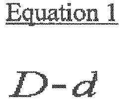

- In
Equation 2, Pend represents a pressure applied to the substrate by the polishing pad at an outermost point in portions of the polishing pad other than the worn portions. -
Equations polishing pad 3 and the pressure applied to thesubstrate 2 by thepolishing pad 3 together, thelarge scale plate 2 may be polished more uniformly.Fig. 6 shows polishing amounts when the travel ranges S1 and S2 are determined by usingEquations Fig. 6 withFig. 2 (not according to the present invention), it may be understood that the polishing deviation ofFig. 6 is much smaller than that ofFig. 2 (not according to the present invention). - The substrate polishing method according to the present disclosure may minimize a difference of polishing amounts between a center portion and a rim portion of a large scale plate.
- In particular, since the substrate polishing method according to the present disclosure considers the wear condition of the polishing pad and the pressure applied to the substrate by the polishing pad together when minimizing a difference of polishing amounts (polishing deviation), the large scale plate may be polished more uniformly.
- Provided is a plate uniformly polished by the polishing method.
| 1: | upper plate | 2: | substrate |
| 3: | polishing pad | ||
| S1: | travel range of the upper plate in the longitudinal direction (x direction) | ||
| S2: | travel range of the upper plate in the transverse direction (y direction) | ||
| a: | length of the substrate in the longitudinal direction (x direction) | ||
| b: | length of the substrate in the transverse direction (y direction) | ||
| D: | diameter of the polishing pad | Peff: | effective pressure |
| D': | diameter of a portion where the pressure applied to the substrate by the polishing pad is equal to or greater than the effective pressure Peff | ||
| Deff: | effective polishing diameter | ||
Claims (1)
- A method for polishing a substrate (2) by moving an upper plate (1) having a polishing pad (3) installed thereto,
wherein the upper plate (1) performs a polishing process along a quadrangular path,
wherein the path forms a square, and
wherein a travel range (S1) by which the upper plate (1) moves in the longitudinal direction of the substrate (2) and a travel range (S2) by which the upper plate (1) moves in the transverse direction of the substrate (2) are respectively 90% to 100% of a diameter (D) of the polishing pad (3) installed to the upper plate (1), wherein S1 and S2 respectively have a smallest value among values calculated by Formulas 1 and 2 below:
 d: double of a radial length of a worn portion of a rim portion of the polishing pad, which does not contact the substrate;D': diameter of a portion where the pressure applied to the substrate by the polishing pad is equal to or greater than an effective pressure (Peff) which is capable of wearing the surface portion of the substrate;Pend: pressure applied to the substrate by the polishing pad at each outermost point in all portions of the polishing pad other than the worn portion which does not contact the substrate; andPeff: pressure applied to the substrate by the polishing pad, which is capable of wearing the surface portion of the substrate.
Applications Claiming Priority (2)
| Application Number | Priority Date | Filing Date | Title |
|---|---|---|---|
| KR1020100074710A KR101504221B1 (en) | 2010-08-02 | 2010-08-02 | Large scale plate and method for uniform polishing of the same |
| PCT/KR2011/005657 WO2012018215A2 (en) | 2010-08-02 | 2011-08-01 | Large substrate, and polishing method of large substrate for uniform polishing |
Publications (3)
| Publication Number | Publication Date |
|---|---|
| EP2602057A2 EP2602057A2 (en) | 2013-06-12 |
| EP2602057A4 EP2602057A4 (en) | 2017-07-05 |
| EP2602057B1 true EP2602057B1 (en) | 2020-02-19 |
Family
ID=45559920
Family Applications (1)
| Application Number | Title | Priority Date | Filing Date |
|---|---|---|---|
| EP11814815.4A Active EP2602057B1 (en) | 2010-08-02 | 2011-08-01 | Large scale plate and method for uniformly polishing large scale plate |
Country Status (6)
| Country | Link |
|---|---|
| US (1) | US8888560B2 (en) |
| EP (1) | EP2602057B1 (en) |
| JP (1) | JP5563161B2 (en) |
| KR (1) | KR101504221B1 (en) |
| CN (1) | CN103052467B (en) |
| WO (1) | WO2012018215A2 (en) |
Families Citing this family (1)
| Publication number | Priority date | Publication date | Assignee | Title |
|---|---|---|---|---|
| CN106670944A (en) * | 2016-12-31 | 2017-05-17 | 上海合晶硅材料有限公司 | Silicon wafer polishing method |
Family Cites Families (17)
| Publication number | Priority date | Publication date | Assignee | Title |
|---|---|---|---|---|
| US1865284A (en) * | 1931-04-21 | 1932-06-28 | Charleston Dry Dock & Machine | Metal plate construction and method of forming the same |
| US3026653A (en) * | 1958-11-03 | 1962-03-27 | Zordo Battista De | Automatic machine for lapping of marble slabs and other similar stones |
| GB8522441D0 (en) * | 1985-09-10 | 1985-10-16 | Lindsey A F | Flat glass |
| JP2657655B2 (en) * | 1988-01-18 | 1997-09-24 | 八千代マイクロサイエンス株式会社 | Aircraft window polishing equipment |
| JP3444715B2 (en) * | 1996-03-15 | 2003-09-08 | 日立造船株式会社 | Polishing apparatus and polishing method using this polishing apparatus |
| JPH1058317A (en) * | 1996-05-16 | 1998-03-03 | Ebara Corp | Polishing method and device for substrate |
| US6413156B1 (en) | 1996-05-16 | 2002-07-02 | Ebara Corporation | Method and apparatus for polishing workpiece |
| WO2002047139A2 (en) | 2000-12-04 | 2002-06-13 | Ebara Corporation | Methode of forming a copper film on a substrate |
| JP2002217143A (en) * | 2001-01-18 | 2002-08-02 | Fujitsu Ltd | Polishing method and polishing apparatus |
| CN101306512A (en) * | 2002-12-27 | 2008-11-19 | 株式会社荏原制作所 | Substrate Polishing Equipment |
| JP4384954B2 (en) * | 2004-08-30 | 2009-12-16 | 篤暢 宇根 | Processing method, processing device, and rectangular flat plate processed product processed by this processing method |
| JP2006278977A (en) * | 2005-03-30 | 2006-10-12 | Fujitsu Ltd | Semiconductor device manufacturing method and polishing method |
| JP2007260783A (en) * | 2006-03-27 | 2007-10-11 | Shiba Giken:Kk | Polishing surface plate, apparatus and method of surface polishing |
| JP5428171B2 (en) * | 2008-03-12 | 2014-02-26 | 東ソー株式会社 | Polishing method |
| JP2010064196A (en) * | 2008-09-11 | 2010-03-25 | Ebara Corp | Substrate polishing device and substrate polishing method |
| JP5388212B2 (en) * | 2009-03-06 | 2014-01-15 | エルジー・ケム・リミテッド | Lower unit for float glass polishing system |
| KR101383600B1 (en) * | 2010-03-11 | 2014-04-11 | 주식회사 엘지화학 | Apparatus and method for monitoring glass plate polishing state |
-
2010
- 2010-08-02 KR KR1020100074710A patent/KR101504221B1/en active Active
-
2011
- 2011-08-01 JP JP2013523093A patent/JP5563161B2/en active Active
- 2011-08-01 EP EP11814815.4A patent/EP2602057B1/en active Active
- 2011-08-01 CN CN201180038080.4A patent/CN103052467B/en active Active
- 2011-08-01 WO PCT/KR2011/005657 patent/WO2012018215A2/en not_active Ceased
-
2013
- 2013-01-29 US US13/753,147 patent/US8888560B2/en active Active
Non-Patent Citations (1)
| Title |
|---|
| None * |
Also Published As
| Publication number | Publication date |
|---|---|
| US20130149939A1 (en) | 2013-06-13 |
| EP2602057A4 (en) | 2017-07-05 |
| CN103052467B (en) | 2015-09-02 |
| EP2602057A2 (en) | 2013-06-12 |
| JP5563161B2 (en) | 2014-07-30 |
| KR20120012631A (en) | 2012-02-10 |
| CN103052467A (en) | 2013-04-17 |
| KR101504221B1 (en) | 2015-03-20 |
| US8888560B2 (en) | 2014-11-18 |
| WO2012018215A2 (en) | 2012-02-09 |
| WO2012018215A3 (en) | 2012-03-29 |
| JP2013535348A (en) | 2013-09-12 |
Similar Documents
| Publication | Publication Date | Title |
|---|---|---|
| US8118646B2 (en) | Carrier for double-side polishing apparatus, double-side polishing apparatus using the same, and double-side polishing method | |
| KR102110919B1 (en) | Double side polishing machine | |
| JP4780142B2 (en) | Wafer manufacturing method | |
| US20150321311A1 (en) | Carrier for use in double-side polishing apparatus and method of double-side polishing wafer | |
| KR102507777B1 (en) | Wafer manufacturing method and wafer | |
| JP5648623B2 (en) | Carrier for double-side polishing apparatus, double-side polishing apparatus and double-side polishing method using the same | |
| WO2012140842A1 (en) | Double-head grinding method and double-head grinding apparatus | |
| CN108349058A (en) | Load-carrying ring, grinding attachment and method for grinding | |
| US20150217425A1 (en) | Double-side polishing method | |
| WO2015055671A1 (en) | Grinding wheel, particularly for grinding processing operations carried out on sheets of glass, ceramic material or similar materials | |
| US10919796B2 (en) | Method for producing glass plate | |
| JP5507799B2 (en) | Semiconductor wafer polishing apparatus and polishing method | |
| US8888560B2 (en) | Method for uniformly polishing large scale plate | |
| CN103817381A (en) | Alignment tool and alignment method for involute internal spline | |
| KR20190124728A (en) | Wafer Manufacturing Method | |
| US20180265144A1 (en) | Elastic crawler and elastic crawler drive mechanism | |
| JP6840639B2 (en) | Carrier for double-sided polishing machine | |
| JP6045960B2 (en) | Band saw | |
| CN117089679B (en) | Lower die assembly and pressure quenching die | |
| JP2006232097A (en) | Wheel | |
| WO2021079685A1 (en) | Gear member | |
| JPH05104184A (en) | Rolling die | |
| CN105269473A (en) | Specially-used abrasive wheel for indium tin oxide (ITO) conducting-film glass | |
| JPH0592323A (en) | Electric discharge cutting machine |
Legal Events
| Date | Code | Title | Description |
|---|---|---|---|
| PUAI | Public reference made under article 153(3) epc to a published international application that has entered the european phase |
Free format text: ORIGINAL CODE: 0009012 |
|
| 17P | Request for examination filed |
Effective date: 20130125 |
|
| AK | Designated contracting states |
Kind code of ref document: A2 Designated state(s): AL AT BE BG CH CY CZ DE DK EE ES FI FR GB GR HR HU IE IS IT LI LT LU LV MC MK MT NL NO PL PT RO RS SE SI SK SM TR |
|
| DAX | Request for extension of the european patent (deleted) | ||
| REG | Reference to a national code |
Ref country code: DE Ref legal event code: R079 Ref document number: 602011065124 Country of ref document: DE Free format text: PREVIOUS MAIN CLASS: B24B0001000000 Ipc: B24B0007200000 |
|
| A4 | Supplementary search report drawn up and despatched |
Effective date: 20170607 |
|
| RIC1 | Information provided on ipc code assigned before grant |
Ipc: B24B 37/04 20120101ALI20170531BHEP Ipc: B24B 37/005 20120101ALI20170531BHEP Ipc: H01L 21/304 20060101ALI20170531BHEP Ipc: B24B 7/20 20060101AFI20170531BHEP Ipc: B24B 49/00 20120101ALI20170531BHEP |
|
| RAP1 | Party data changed (applicant data changed or rights of an application transferred) |
Owner name: LG CHEM, LTD. |
|
| STAA | Information on the status of an ep patent application or granted ep patent |
Free format text: STATUS: EXAMINATION IS IN PROGRESS |
|
| 17Q | First examination report despatched |
Effective date: 20181211 |
|
| GRAP | Despatch of communication of intention to grant a patent |
Free format text: ORIGINAL CODE: EPIDOSNIGR1 |
|
| STAA | Information on the status of an ep patent application or granted ep patent |
Free format text: STATUS: GRANT OF PATENT IS INTENDED |
|
| INTG | Intention to grant announced |
Effective date: 20191119 |
|
| GRAS | Grant fee paid |
Free format text: ORIGINAL CODE: EPIDOSNIGR3 |
|
| GRAA | (expected) grant |
Free format text: ORIGINAL CODE: 0009210 |
|
| STAA | Information on the status of an ep patent application or granted ep patent |
Free format text: STATUS: THE PATENT HAS BEEN GRANTED |
|
| AK | Designated contracting states |
Kind code of ref document: B1 Designated state(s): AL AT BE BG CH CY CZ DE DK EE ES FI FR GB GR HR HU IE IS IT LI LT LU LV MC MK MT NL NO PL PT RO RS SE SI SK SM TR |
|
| REG | Reference to a national code |
Ref country code: GB Ref legal event code: FG4D |
|
| REG | Reference to a national code |
Ref country code: CH Ref legal event code: EP |
|
| REG | Reference to a national code |
Ref country code: DE Ref legal event code: R096 Ref document number: 602011065124 Country of ref document: DE |
|
| REG | Reference to a national code |
Ref country code: AT Ref legal event code: REF Ref document number: 1234386 Country of ref document: AT Kind code of ref document: T Effective date: 20200315 |
|
| REG | Reference to a national code |
Ref country code: IE Ref legal event code: FG4D |
|
| REG | Reference to a national code |
Ref country code: NL Ref legal event code: MP Effective date: 20200219 |
|
| PG25 | Lapsed in a contracting state [announced via postgrant information from national office to epo] |
Ref country code: NO Free format text: LAPSE BECAUSE OF FAILURE TO SUBMIT A TRANSLATION OF THE DESCRIPTION OR TO PAY THE FEE WITHIN THE PRESCRIBED TIME-LIMIT Effective date: 20200519 Ref country code: FI Free format text: LAPSE BECAUSE OF FAILURE TO SUBMIT A TRANSLATION OF THE DESCRIPTION OR TO PAY THE FEE WITHIN THE PRESCRIBED TIME-LIMIT Effective date: 20200219 Ref country code: RS Free format text: LAPSE BECAUSE OF FAILURE TO SUBMIT A TRANSLATION OF THE DESCRIPTION OR TO PAY THE FEE WITHIN THE PRESCRIBED TIME-LIMIT Effective date: 20200219 |
|
| REG | Reference to a national code |
Ref country code: LT Ref legal event code: MG4D |
|
| PG25 | Lapsed in a contracting state [announced via postgrant information from national office to epo] |
Ref country code: BG Free format text: LAPSE BECAUSE OF FAILURE TO SUBMIT A TRANSLATION OF THE DESCRIPTION OR TO PAY THE FEE WITHIN THE PRESCRIBED TIME-LIMIT Effective date: 20200519 Ref country code: IS Free format text: LAPSE BECAUSE OF FAILURE TO SUBMIT A TRANSLATION OF THE DESCRIPTION OR TO PAY THE FEE WITHIN THE PRESCRIBED TIME-LIMIT Effective date: 20200619 Ref country code: GR Free format text: LAPSE BECAUSE OF FAILURE TO SUBMIT A TRANSLATION OF THE DESCRIPTION OR TO PAY THE FEE WITHIN THE PRESCRIBED TIME-LIMIT Effective date: 20200520 Ref country code: LV Free format text: LAPSE BECAUSE OF FAILURE TO SUBMIT A TRANSLATION OF THE DESCRIPTION OR TO PAY THE FEE WITHIN THE PRESCRIBED TIME-LIMIT Effective date: 20200219 Ref country code: SE Free format text: LAPSE BECAUSE OF FAILURE TO SUBMIT A TRANSLATION OF THE DESCRIPTION OR TO PAY THE FEE WITHIN THE PRESCRIBED TIME-LIMIT Effective date: 20200219 Ref country code: HR Free format text: LAPSE BECAUSE OF FAILURE TO SUBMIT A TRANSLATION OF THE DESCRIPTION OR TO PAY THE FEE WITHIN THE PRESCRIBED TIME-LIMIT Effective date: 20200219 |
|
| PG25 | Lapsed in a contracting state [announced via postgrant information from national office to epo] |
Ref country code: NL Free format text: LAPSE BECAUSE OF FAILURE TO SUBMIT A TRANSLATION OF THE DESCRIPTION OR TO PAY THE FEE WITHIN THE PRESCRIBED TIME-LIMIT Effective date: 20200219 |
|
| PG25 | Lapsed in a contracting state [announced via postgrant information from national office to epo] |
Ref country code: ES Free format text: LAPSE BECAUSE OF FAILURE TO SUBMIT A TRANSLATION OF THE DESCRIPTION OR TO PAY THE FEE WITHIN THE PRESCRIBED TIME-LIMIT Effective date: 20200219 Ref country code: DK Free format text: LAPSE BECAUSE OF FAILURE TO SUBMIT A TRANSLATION OF THE DESCRIPTION OR TO PAY THE FEE WITHIN THE PRESCRIBED TIME-LIMIT Effective date: 20200219 Ref country code: SK Free format text: LAPSE BECAUSE OF FAILURE TO SUBMIT A TRANSLATION OF THE DESCRIPTION OR TO PAY THE FEE WITHIN THE PRESCRIBED TIME-LIMIT Effective date: 20200219 Ref country code: PT Free format text: LAPSE BECAUSE OF FAILURE TO SUBMIT A TRANSLATION OF THE DESCRIPTION OR TO PAY THE FEE WITHIN THE PRESCRIBED TIME-LIMIT Effective date: 20200712 Ref country code: SM Free format text: LAPSE BECAUSE OF FAILURE TO SUBMIT A TRANSLATION OF THE DESCRIPTION OR TO PAY THE FEE WITHIN THE PRESCRIBED TIME-LIMIT Effective date: 20200219 Ref country code: CZ Free format text: LAPSE BECAUSE OF FAILURE TO SUBMIT A TRANSLATION OF THE DESCRIPTION OR TO PAY THE FEE WITHIN THE PRESCRIBED TIME-LIMIT Effective date: 20200219 Ref country code: LT Free format text: LAPSE BECAUSE OF FAILURE TO SUBMIT A TRANSLATION OF THE DESCRIPTION OR TO PAY THE FEE WITHIN THE PRESCRIBED TIME-LIMIT Effective date: 20200219 Ref country code: EE Free format text: LAPSE BECAUSE OF FAILURE TO SUBMIT A TRANSLATION OF THE DESCRIPTION OR TO PAY THE FEE WITHIN THE PRESCRIBED TIME-LIMIT Effective date: 20200219 Ref country code: RO Free format text: LAPSE BECAUSE OF FAILURE TO SUBMIT A TRANSLATION OF THE DESCRIPTION OR TO PAY THE FEE WITHIN THE PRESCRIBED TIME-LIMIT Effective date: 20200219 |
|
| REG | Reference to a national code |
Ref country code: AT Ref legal event code: MK05 Ref document number: 1234386 Country of ref document: AT Kind code of ref document: T Effective date: 20200219 |
|
| REG | Reference to a national code |
Ref country code: DE Ref legal event code: R097 Ref document number: 602011065124 Country of ref document: DE |
|
| PLBE | No opposition filed within time limit |
Free format text: ORIGINAL CODE: 0009261 |
|
| STAA | Information on the status of an ep patent application or granted ep patent |
Free format text: STATUS: NO OPPOSITION FILED WITHIN TIME LIMIT |
|
| 26N | No opposition filed |
Effective date: 20201120 |
|
| PG25 | Lapsed in a contracting state [announced via postgrant information from national office to epo] |
Ref country code: IT Free format text: LAPSE BECAUSE OF FAILURE TO SUBMIT A TRANSLATION OF THE DESCRIPTION OR TO PAY THE FEE WITHIN THE PRESCRIBED TIME-LIMIT Effective date: 20200219 Ref country code: AT Free format text: LAPSE BECAUSE OF FAILURE TO SUBMIT A TRANSLATION OF THE DESCRIPTION OR TO PAY THE FEE WITHIN THE PRESCRIBED TIME-LIMIT Effective date: 20200219 |
|
| PG25 | Lapsed in a contracting state [announced via postgrant information from national office to epo] |
Ref country code: PL Free format text: LAPSE BECAUSE OF FAILURE TO SUBMIT A TRANSLATION OF THE DESCRIPTION OR TO PAY THE FEE WITHIN THE PRESCRIBED TIME-LIMIT Effective date: 20200219 Ref country code: SI Free format text: LAPSE BECAUSE OF FAILURE TO SUBMIT A TRANSLATION OF THE DESCRIPTION OR TO PAY THE FEE WITHIN THE PRESCRIBED TIME-LIMIT Effective date: 20200219 |
|
| PG25 | Lapsed in a contracting state [announced via postgrant information from national office to epo] |
Ref country code: MC Free format text: LAPSE BECAUSE OF FAILURE TO SUBMIT A TRANSLATION OF THE DESCRIPTION OR TO PAY THE FEE WITHIN THE PRESCRIBED TIME-LIMIT Effective date: 20200219 |
|
| REG | Reference to a national code |
Ref country code: CH Ref legal event code: PL |
|
| PG25 | Lapsed in a contracting state [announced via postgrant information from national office to epo] |
Ref country code: LU Free format text: LAPSE BECAUSE OF NON-PAYMENT OF DUE FEES Effective date: 20200801 Ref country code: LI Free format text: LAPSE BECAUSE OF NON-PAYMENT OF DUE FEES Effective date: 20200831 Ref country code: CH Free format text: LAPSE BECAUSE OF NON-PAYMENT OF DUE FEES Effective date: 20200831 |
|
| REG | Reference to a national code |
Ref country code: BE Ref legal event code: MM Effective date: 20200831 |
|
| PG25 | Lapsed in a contracting state [announced via postgrant information from national office to epo] |
Ref country code: IE Free format text: LAPSE BECAUSE OF NON-PAYMENT OF DUE FEES Effective date: 20200801 Ref country code: BE Free format text: LAPSE BECAUSE OF NON-PAYMENT OF DUE FEES Effective date: 20200831 |
|
| PG25 | Lapsed in a contracting state [announced via postgrant information from national office to epo] |
Ref country code: TR Free format text: LAPSE BECAUSE OF FAILURE TO SUBMIT A TRANSLATION OF THE DESCRIPTION OR TO PAY THE FEE WITHIN THE PRESCRIBED TIME-LIMIT Effective date: 20200219 Ref country code: MT Free format text: LAPSE BECAUSE OF FAILURE TO SUBMIT A TRANSLATION OF THE DESCRIPTION OR TO PAY THE FEE WITHIN THE PRESCRIBED TIME-LIMIT Effective date: 20200219 Ref country code: CY Free format text: LAPSE BECAUSE OF FAILURE TO SUBMIT A TRANSLATION OF THE DESCRIPTION OR TO PAY THE FEE WITHIN THE PRESCRIBED TIME-LIMIT Effective date: 20200219 |
|
| PG25 | Lapsed in a contracting state [announced via postgrant information from national office to epo] |
Ref country code: MK Free format text: LAPSE BECAUSE OF FAILURE TO SUBMIT A TRANSLATION OF THE DESCRIPTION OR TO PAY THE FEE WITHIN THE PRESCRIBED TIME-LIMIT Effective date: 20200219 Ref country code: AL Free format text: LAPSE BECAUSE OF FAILURE TO SUBMIT A TRANSLATION OF THE DESCRIPTION OR TO PAY THE FEE WITHIN THE PRESCRIBED TIME-LIMIT Effective date: 20200219 |
|
| PGFP | Annual fee paid to national office [announced via postgrant information from national office to epo] |
Ref country code: DE Payment date: 20250721 Year of fee payment: 15 |
|
| PGFP | Annual fee paid to national office [announced via postgrant information from national office to epo] |
Ref country code: GB Payment date: 20250722 Year of fee payment: 15 |
|
| PGFP | Annual fee paid to national office [announced via postgrant information from national office to epo] |
Ref country code: FR Payment date: 20250725 Year of fee payment: 15 |