EP2602000A1 - Implantable electrode lead - Google Patents
Implantable electrode lead Download PDFInfo
- Publication number
- EP2602000A1 EP2602000A1 EP12192386.6A EP12192386A EP2602000A1 EP 2602000 A1 EP2602000 A1 EP 2602000A1 EP 12192386 A EP12192386 A EP 12192386A EP 2602000 A1 EP2602000 A1 EP 2602000A1
- Authority
- EP
- European Patent Office
- Prior art keywords
- electrode
- lead
- shape
- electrode lead
- supply line
- Prior art date
- Legal status (The legal status is an assumption and is not a legal conclusion. Google has not performed a legal analysis and makes no representation as to the accuracy of the status listed.)
- Granted
Links
Images


Classifications
-
- A—HUMAN NECESSITIES
- A61—MEDICAL OR VETERINARY SCIENCE; HYGIENE
- A61N—ELECTROTHERAPY; MAGNETOTHERAPY; RADIATION THERAPY; ULTRASOUND THERAPY
- A61N1/00—Electrotherapy; Circuits therefor
- A61N1/02—Details
- A61N1/04—Electrodes
- A61N1/05—Electrodes for implantation or insertion into the body, e.g. heart electrode
- A61N1/056—Transvascular endocardial electrode systems
-
- A—HUMAN NECESSITIES
- A61—MEDICAL OR VETERINARY SCIENCE; HYGIENE
- A61N—ELECTROTHERAPY; MAGNETOTHERAPY; RADIATION THERAPY; ULTRASOUND THERAPY
- A61N1/00—Electrotherapy; Circuits therefor
- A61N1/02—Details
- A61N1/08—Arrangements or circuits for monitoring, protecting, controlling or indicating
- A61N1/086—Magnetic resonance imaging [MRI] compatible leads
Definitions
- the invention relates to an implantable elongate electrode lead comprising an electrode body, at least one electrode pole connected to the electrode body, a terminal and an electrical lead electrically connected to the electrode terminal and extending from the electrode terminal to the terminal at a proximal end of the electrode lead.
- Such electrode lines are connected, for example, to implantable cardiac stimulators such as cardiac pacemakers, cardioverter, defibrillators or the like, but can also serve as a mapping catheter for diagnosis or neurostimulation.
- implantable cardiac stimulators such as cardiac pacemakers, cardioverter, defibrillators or the like, but can also serve as a mapping catheter for diagnosis or neurostimulation.
- Such electrode lines have the disadvantage that their electrical conductor can heat up in a magnetic resonance tomograph, because the magnetic fields prevailing in the magnetic resonance tomographs induce not inconsiderable electrical currents in the electrical conductor. Therefore, cardiac pacemaker patients today can usually not be examined or only to a limited extent in a magnetic resonance tomograph.
- implantable cardiac pacemakers or defibrillators typically have at least one pacing lead connected to their proximal end for connection to the pacemaker or defibrillator with a standard electrical connection and one or more electrode poles at their distal end provided for placement in the heart.
- Such an electrode pole serves to deliver electrical impulses, for example to the tissue (myocardium) of the heart or to sense electric fields, in order to be able to sense an activity, for example a cardiac activity, within the framework of so-called sensing.
- electrode poles typically form electrically conductive surface portions of an electrode lead. Electrode poles are typically provided as a ring electrode in the form of a ring around the electrode lead or in the form of a tip or tip electrode at the distal end of the electrode lead.
- the electrode poles are electrically conductively connected via one or more electrical supply lines to contacts of the electrical connection of the electrode line at its proximal end.
- the electrode lines extend at the proximal end thereof and the electrode poles at the distal end of the electrode line one or more electrical leads electrically connecting one or more of the electrode poles to one or more of the contacts.
- Such leads contain electrical conductors required for the functions of the respective electrode line and are therefore exposed to the risk that electrical currents are induced in them by external alternating magnetic fields, which can lead, for example, to undesired heating of the leads or the electrode poles connected to them or to discharge corresponding currents can lead to the surrounding tissue via the electrode poles and thus to a heating of the surrounding tissue.
- the aim of the invention is to provide an electrode lead which can be expected to produce less heat than conventional electrode leads in an MRI environment.
- an implantable electrode lead comprising an electrode body, at least one electrode pole connected to the electrode body, a terminal and an electrical lead electrically connected to the electrode pole and extending from the electrode pole to the terminal at a proximal end the electrode line extends.
- the electrical supply line is designed to take such a modified form after implantation of the electrode line in a form variable supply line section, which in the form variable Lead portion after deformation causes a higher inductance than before the deformation, wherein the inductance is at least 0.1 uH.
- an implantable electrode lead comprising an electrode body, at least one electrode pole connected to the electrode body, a terminal and an electrical lead electrically connected to the electrode pole and extending from the electrode pole to the terminal at a proximal one End of the electrode line extends, wherein the implantable electrode line has an outer shell, within which the supply line is arranged.
- the electrical supply line is formed, after implantation of the electrode line in a form variable supply line section to assume a shape modified from its original shape.
- the supply line is also designed and arranged within the envelope so that the supply line in its form variable supply line section is dimensionally variable relative to the outer shell and within the outer shell.
- the shell thus does not take the shape of the lead portion when it assumes its changed shape.
- the intended effect of reducing the heat build-up of these electrodes is due to detuning of the antenna lead resonant properties for the MRI arrays, either by length or geometry variation and / or the addition of inductance.
- the casing is preferably expandable in the region of the form-variable feed line section, and the feed section and casing, which are variable in shape, are designed such that the casing radially expands when the form-changing feed section changes shape.
- the invention includes the recognition that, although hitherto, a wide variety of design modifications and also the integration of electronic components in electrode lines have been known in order to reduce the MRI-induced heat development.
- many of the above-mentioned solutions for reducing MR induced heat generation in electrode leads require additional design features that make the overall structure of an electrode lead much more complex and add joints so that the reliability of these electrode leads is likely to decrease over conventional electrode leads.
- the changed shape of the shape-changing supply line section after implantation of the electrode line is a helical shape.
- This is suitable for imparting a desired inductance to the variable-shape lead-in section and can additionally serve to fix the electrode lead after implantation, in that not only the lead itself, but also the outer shape of the electrode lead, including the outer sleeve, assumes a helical shape in the region of the shape-changeable lead-in section. eg on the wall of a blood vessel.
- the helical shape has at least 15 turns, in particular more than 30 turns.
- the individual turns of the helical shape are preferably at a distance from each other.
- the modified form preferably causes an inductance of more than 1 ⁇ H.
- the changed shape of the lead is pre-embossed.
- the electrode line can be made of a memory metal so that it assumes the changed shape after exceeding a jumping temperature.
- the electrode lead can be preformed and resiliently biased during implantation by means of a stiffer removable insertion aid, so that the lead after removal of the insertion on the bias takes the modified form.
- the insertion aid is preferably a sheath catheter or a stylet.
- a supply line comprising an electrical conductor that at least the electrical conductor in the region of the form-variable supply line section is enclosed by a jacket which is pre-embossed with the changed shape of the supply line.
- the jacket is in this case preferably formed by a memory material.
- the jacket is formed of insulating plastic.
- the shape-changing lead portion after deformation has a diameter of more than 8 mm or, if possible, more than 10mm. This increases the inductance of the supply section.
- variable-shape lead portion is preferably provided in the vicinity of a distal end of the electrode lead, but may also be located at a proximal end of the electrode lead or in the middle thereof. It is preferably provided only a variable-shape lead portion, but it can also be provided several of them.
- the aim of the invention is thus achieved with a temporarily or permanently implantable electrode or sensor line with at least one electrical lead, which is constructed so that one or more parts of the or the entire electrical lead aligns coil-shaped or crimped after implantation.
- the change in shape is reversible and may be e.g. by introducing a stiff stylet or similar be undone at least temporarily.
- FIG. 1 an electrode lead (100) according to the invention is shown prior to implantation.
- the electrode lead (100) has an insulated lead (110), an electrode bipolar pole (Tip: 120, ring 130) and a corresponding lead connector (140), and a temporary insertion aid (150) to be stretched upon implantation Mold.
- This introducer (150) is executed in the example shown as an introducer sheath or hose over the electrode line. Alternatively, however, a stiff stylet or a stylet can be used.
- variable-shape lead portion forms a coil with a diameter of 3 - 15 mm in the distal region of the electrode lead.
- the altered shape of the variable-shape lead portion (260) is caused either by preforming a jacket of the lead and / or an electrical conductor of the lead or by a shape memory material (polymer or metal), by the body heat or an additional energy input (heat, Light) realized the formation.
- the helical coil can be formed by winding the entire electrode line together with the feed line located in it, or else preferably forming a helix of the feed line within the outer sheath of the electrode line, whereby the outer sheath (270) widens like a balloon. The latter is in FIG. 2 indicated.
- the inductance of the helix coil formed by the variable-shape lead portion is about 1 ⁇ H, ie the coil has about 30 turns on a length of 10 cm with a diameter of 1.2 cm. Together with the tissue impedance This results in a voltage divider that reduces the electrode heating by at least a factor of 2.
- the electrode line thus formed is MRI-compatible and has no deviations from conventional electrode lines at the quality-relevant joints. Likewise, no additional electronic components in the electrode are needed.
- the crimping takes place during or after implantation.
- the conformable lead portion assumes a preformed / pre-punched shape.
- this takes place by heat influence (memory shape) - i. due to the body heat or warming of the mandrin.
- the crimp is preferably formed in the distal region, if appropriate additionally in the proximal region or else only in the proximal region.
- a plurality of crimped areas along the electrode line are pronounced. These are preferably adapted to the local anatomical conditions, e.g. a form in the superior vena cava, a second form in the atrium, and a third form in the ventricle.
- the electrode leads for these crimped designs preferably have a thickness of less than 5F.
Abstract
Description
Die Erfindung betrifft eine implantierbare längsgestreckte Elektrodenleitung mit einem Elektrodenkörper, wenigstens einem mit dem Elektrodenkörper verbundenen Elektrodenpol, einem Anschluss und einer elektrischen Zuleitung, die elektrisch mit dem Elektrodenpol verbunden ist und die sich von dem Elektrodenpol zu dem Anschluss an einem proximalen Ende der Elektrodenleitung erstreckt.The invention relates to an implantable elongate electrode lead comprising an electrode body, at least one electrode pole connected to the electrode body, a terminal and an electrical lead electrically connected to the electrode terminal and extending from the electrode terminal to the terminal at a proximal end of the electrode lead.
Derartige Elektrodenleitungen werden beispielsweise an implantierbare Herzstimulatoren wie Herzschrittmacher, Kardioverter, Defibrillatoren oder dergleichen angeschlossen, können aber auch als Mapping Katheter zur Diagnose oder zur Neurostimulation dienen.Such electrode lines are connected, for example, to implantable cardiac stimulators such as cardiac pacemakers, cardioverter, defibrillators or the like, but can also serve as a mapping catheter for diagnosis or neurostimulation.
Solche Elektrodenleitungen haben den Nachteil, dass sich ihr elektrischer Leiter in einem Kernspintomografen erwärmen kann, weil die im Kernspintomografen herrschenden wechselnden Magnetfelder in dem elektrischen Leiter nicht unbeachtliche elektrische Ströme induzieren. Deshalb können Herzschrittmacherpatienten heutzutage in der Regel nicht oder nur eingeschränkt in einem Kernspintomografen untersucht werden.Such electrode lines have the disadvantage that their electrical conductor can heat up in a magnetic resonance tomograph, because the magnetic fields prevailing in the magnetic resonance tomographs induce not inconsiderable electrical currents in the electrical conductor. Therefore, cardiac pacemaker patients today can usually not be examined or only to a limited extent in a magnetic resonance tomograph.
An implantierbaren Herzschrittmachern oder Defibrillatoren sind nämlich typischerweise wenigstens eine Stimulationselektrodenleitung angeschlossen, die an ihrem proximalen, zum Anschluss an den Herzschrittmacher oder Defibrillator vorgesehenen Ende einen standardisierten elektrischen Anschluss aufweist und an ihrem distalen, zur Platzierung im Herzen vorgesehenen Ende einen oder mehrere Elektrodenpole aufweist. Ein solcher Elektrodenpol dient zur Abgabe elektrischer Impulse, beispielsweise an das Gewebe (Myokard) des Herzens oder zum Abfühlen elektrischer Felder, um im Rahmen des sogenannten Sensings eine Aktivität, beispielsweise eine Herzaktivität, abfühlen zu können.Namely, implantable cardiac pacemakers or defibrillators typically have at least one pacing lead connected to their proximal end for connection to the pacemaker or defibrillator with a standard electrical connection and one or more electrode poles at their distal end provided for placement in the heart. Such an electrode pole serves to deliver electrical impulses, for example to the tissue (myocardium) of the heart or to sense electric fields, in order to be able to sense an activity, for example a cardiac activity, within the framework of so-called sensing.
Zu diesen Zwecken bilden Elektrodenpole typischerweise elektrisch leitende Oberflächenabschnitte einer Elektrodenleitung. Elektrodenpole sind typischerweise als Ringelektrode in Form eines Rings um die Elektrodenleitung oder in Form einer Spitzen- oder Tippelektrode am distalen Ende der Elektrodenleitung vorgesehen.For these purposes, electrode poles typically form electrically conductive surface portions of an electrode lead. Electrode poles are typically provided as a ring electrode in the form of a ring around the electrode lead or in the form of a tip or tip electrode at the distal end of the electrode lead.
Die Elektrodenpole sind über eine oder mehrere elektrische Zuleitungen mit Kontakten des elektrischen Anschlusses der Elektrodenleitung an deren proximalem Ende elektrisch leitend verbunden. Somit verlaufen zwischen den Kontakten des elektrischen Anschlusses die Elektrodenleitungen an deren proximalem Ende und den Elektrodenpolen am distalen Ende der Elektrodenleitung ein oder mehrere elektrische Zuleitungen, die einen oder mehrere der Elektrodenpole mit einem oder mehreren der Kontakte elektrisch verbinden.The electrode poles are electrically conductively connected via one or more electrical supply lines to contacts of the electrical connection of the electrode line at its proximal end. Thus, between the contacts of the electrical connection, the electrode lines extend at the proximal end thereof and the electrode poles at the distal end of the electrode line one or more electrical leads electrically connecting one or more of the electrode poles to one or more of the contacts.
Solche Zuleitungen enthalten für die Funktionen der jeweiligen Elektrodenleitung erforderliche elektrische Leiter und sind daher der Gefahr ausgesetzt, dass in ihnen durch äußere Wechselmagnetfelder elektrische Ströme induziert werden, die beispielsweise zu einer unerwünschten Erwärmung der Zuleitungen oder der mit ihr verbundenen Elektrodenpole führen können oder die zur Abgabe entsprechender Ströme über die Elektrodenpole an umgebendes Gewebe und damit zu einer Erwärmung des umgebenden Gewebes führen können.Such leads contain electrical conductors required for the functions of the respective electrode line and are therefore exposed to the risk that electrical currents are induced in them by external alternating magnetic fields, which can lead, for example, to undesired heating of the leads or the electrode poles connected to them or to discharge corresponding currents can lead to the surrounding tissue via the electrode poles and thus to a heating of the surrounding tissue.
Ziel der Erfindung ist es, eine Elektrodenleitung zu schaffen, die eine geringere Wärmeentwicklung als herkömmliche Elektrodenleitungen in einer MRT-Umgebung erwarten lässt.The aim of the invention is to provide an electrode lead which can be expected to produce less heat than conventional electrode leads in an MRI environment.
Erfindungsgemäß wird dieses Ziel durch eine implantierbare Elektrodenleitung erreicht, die einen Elektrodenkörper, wenigstens einen mit dem Elektrodenkörper verbundenen Elektrodenpol, einen Anschluss und eine elektrische Zuleitung aufweist, die elektrisch mit dem Elektrodenpol verbunden ist und die sich von dem Elektrodenpol zu dem Anschluss an einem proximalen Ende der Elektrodenleitung erstreckt. Die elektrische Zuleitung ist ausgebildet, nach Implantation der Elektrodenleitung in einem formveränderlichen Zuleitungsabschnitt eine solche veränderte Form einzunehmen, die in dem formveränderlichen Zuleitungsabschnitt nach Verformung eine höhere Induktivität als vor der Verformung bewirkt, wobei die Induktivität mindestens 0,1 µH beträgt.According to the invention, this object is achieved by an implantable electrode lead comprising an electrode body, at least one electrode pole connected to the electrode body, a terminal and an electrical lead electrically connected to the electrode pole and extending from the electrode pole to the terminal at a proximal end the electrode line extends. The electrical supply line is designed to take such a modified form after implantation of the electrode line in a form variable supply line section, which in the form variable Lead portion after deformation causes a higher inductance than before the deformation, wherein the inductance is at least 0.1 uH.
Erfindungsgemäß wird dieses Ziel auch durch eine implantierbare Elektrodenleitung erreicht, die einen Elektrodenkörper, wenigstens einen mit dem Elektrodenkörper verbundenen Elektrodenpol, einen Anschluss und eine elektrische Zuleitung aufweist, die elektrisch mit dem Elektrodenpol verbunden ist und die sich von dem Elektrodenpol zu dem Anschluss an einem proximalen Ende der Elektrodenleitung erstreckt, wobei die implantierbare Elektrodenleitung eine äußere Hülle aufweist, innerhalb derer die Zuleitung angeordnet ist. Die elektrische Zuleitung ist ausgebildet, nach Implantation der Elektrodenleitung in einem formveränderlichen Zuleitungsabschnitt eine gegenüber ihrer ursprünglichen Form veränderte Form einzunehmen. Hierbei ist die Zuleitung außerdem so ausgebildet und innerhalb der Hülle so angeordnet, dass die Zuleitung in ihrem formveränderlichen Zuleitungsabschnitt relativ zur äußeren Hülle und innerhalb der äußeren Hülle formveränderlich ist.According to the invention, this object is also achieved by an implantable electrode lead comprising an electrode body, at least one electrode pole connected to the electrode body, a terminal and an electrical lead electrically connected to the electrode pole and extending from the electrode pole to the terminal at a proximal one End of the electrode line extends, wherein the implantable electrode line has an outer shell, within which the supply line is arranged. The electrical supply line is formed, after implantation of the electrode line in a form variable supply line section to assume a shape modified from its original shape. In this case, the supply line is also designed and arranged within the envelope so that the supply line in its form variable supply line section is dimensionally variable relative to the outer shell and within the outer shell.
Die Hülle nimmt somit nicht die Form des Zuleitungsabschnitts ein, wenn dieser seine veränderte Form einnimmt.The shell thus does not take the shape of the lead portion when it assumes its changed shape.
In beiden Fällen beruht der beabsichtigte Effekt der Reduktion der Wärmeentwicklung dieser Elektroden auf der Verstimmung der für die MRT-Felder resonanten Antenneneigenschaften der Elektrodenleitung, entweder durch eine Längen- bzw. Geometrievariation und/oder das Hinzufügen einer Induktivität.In either case, the intended effect of reducing the heat build-up of these electrodes is due to detuning of the antenna lead resonant properties for the MRI arrays, either by length or geometry variation and / or the addition of inductance.
Im zweitgenannten Fall ist die Hülle im Bereich des formveränderlichen Zuleitungsabschnitts vorzugsweise dehnbar und formveränderlicher Zuleitungsabschnitt und Hülle sind so ausgebildet, dass sich die Hülle bei Formveränderung des formveränderlichen Zuleitungsabschnitts radial ausdehnt.In the second-mentioned case, the casing is preferably expandable in the region of the form-variable feed line section, and the feed section and casing, which are variable in shape, are designed such that the casing radially expands when the form-changing feed section changes shape.
In beiden Fällen ergibt sich eine MRT-kompatible Elektrodenleitung, die nach der Implantation ganz oder teilweise eine gewendelte Form einnimmt und somit eine für die MRT-HF-Felder schlecht abgestimmte Antenne darstellt und damit die MRT-induzierte Wärmeentwicklung reduziert.In both cases results in an MRI-compatible electrode lead, which after implantation wholly or partially assumes a coiled shape and thus one for the MRI-RF fields represents poorly tuned antenna and thus reduces MRI-induced heat generation.
Die Erfindung schließt die Erkenntnis ein, dass bislang zwar verschiedenste Bauformmodifikationen und auch die Integration von elektronischen Bauelementen in Elektrodenleitungen bekannt sind, um die MRT-induzierte Wärmeentwicklung zu reduzieren. Jedoch bedürfen viele der oben genannten Lösungen zur Reduktion der MRT-induzierten Wärmeentwicklung in Elektrodenleitungen zusätzlicher Konstruktionsmerkmale, die den Gesamtaufbau einer Elektrodenleitung wesentlich komplexer machen und Fügestellen hinzufügen, so dass die Zuverlässigkeit dieser Elektrodenleitungen gegenüber herkömmlichen Elektrodenleitungen wahrscheinlich abnehmen wird.The invention includes the recognition that, although hitherto, a wide variety of design modifications and also the integration of electronic components in electrode lines have been known in order to reduce the MRI-induced heat development. However, many of the above-mentioned solutions for reducing MR induced heat generation in electrode leads require additional design features that make the overall structure of an electrode lead much more complex and add joints so that the reliability of these electrode leads is likely to decrease over conventional electrode leads.
Gemäß einer bevorzugten Ausführungsform ist die veränderte Form des formveränderlichen Zuleitungsabschnitts nach Implantation der Elektrodenleitung eine Helixform. Diese ist geeignet, dem formveränderlichen Zuleitungsabschnitt eine gewünschte Induktivität zu verleihen und kann darüber hinaus auch einer Fixierung der Elektrodenleitung nach Implantation dienen, indem nicht nur die Zuleitung selbst, sondern auch die Außenform der Elektrodenleitung einschließlich äußerer Hülle im Bereich des formveränderlichen Zuleitungsabschnitts eine Helixform annimmt, die sich z.B. an die Wand eines Blutgefäßes anlegt.According to a preferred embodiment, the changed shape of the shape-changing supply line section after implantation of the electrode line is a helical shape. This is suitable for imparting a desired inductance to the variable-shape lead-in section and can additionally serve to fix the electrode lead after implantation, in that not only the lead itself, but also the outer shape of the electrode lead, including the outer sleeve, assumes a helical shape in the region of the shape-changeable lead-in section. eg on the wall of a blood vessel.
Vorzugsweise weist die Helixform wenigstens 15 Windungen, insbesondere mehr als 30 Windungen, auf. Die einzelnen Windungen der Helixform haben vorzugsweise einen Abstand voneinander. Die veränderte Form bewirkt vorzugsweise eine Induktivität von mehr als 1 µH.Preferably, the helical shape has at least 15 turns, in particular more than 30 turns. The individual turns of the helical shape are preferably at a distance from each other. The modified form preferably causes an inductance of more than 1 μH.
Vorzugsweise ist die veränderte Form der Zuleitung voreingeprägt. Hierzu kann die Elektrodenleitung aus einem Memory-Metall so hergestellt sein, dass sie nach Überschreiten einer Springtemperatur die veränderte Form einnimmt. Alternativ oder zusätzlich kann die Elektrodenleitung vorgeformt und beim Implantieren mittels einer steiferen entfernbaren Einführhilfe elastisch vorgespannt sein, so dass die Zuleitung nach Entfernen der Einführhilfe auf der Vorspannung die veränderte Form einnimmt. Hierbei ist die Einführhilfe vorzugsweise ein Hüllkatheter oder ein Stylet.Preferably, the changed shape of the lead is pre-embossed. For this purpose, the electrode line can be made of a memory metal so that it assumes the changed shape after exceeding a jumping temperature. Alternatively or additionally, the electrode lead can be preformed and resiliently biased during implantation by means of a stiffer removable insertion aid, so that the lead after removal of the insertion on the bias takes the modified form. In this case, the insertion aid is preferably a sheath catheter or a stylet.
Zum Erzielen einer voreingeprägten Form kann bei einer Zuleitung, die einen elektrischen Leiter umfasst, vorgesehen sein, dass wenigstens der elektrische Leiter im Bereich des formveränderlichen Zuleitungsabschnitts von einem Mantel umschlossen ist, dem veränderte Form der Zuleitung voreingeprägt ist. Der Mantel ist hierbei vorzugsweise von einem Memorymaterial gebildet. Außerdem ist es bevorzugt, wenn der Mantel von isolierendem Kunststoff gebildet ist.In order to achieve a pre-embossed form, it may be provided in the case of a supply line comprising an electrical conductor that at least the electrical conductor in the region of the form-variable supply line section is enclosed by a jacket which is pre-embossed with the changed shape of the supply line. The jacket is in this case preferably formed by a memory material. In addition, it is preferred if the jacket is formed of insulating plastic.
Vorzugsweise hat der formveränderliche Zuleitungsabschnitt nach Formänderung einen Durchmesser von mehr als 8 mm oder, wenn möglich, mehr als 10mm. Dies erhöht die Induktivität des Zuleitungsabschnitts.Preferably, the shape-changing lead portion after deformation has a diameter of more than 8 mm or, if possible, more than 10mm. This increases the inductance of the supply section.
Der formveränderliche Zuleitungsabschnitt ist vorzugsweise in der Nähe eines distalen Endes der Elektrodenleitung vorgesehen, kann sich aber auch an einem proximalen Ende der Elektrodenleitung befinden oder in deren Mitte. Es ist vorzugsweise nur ein formveränderlicher Zuleitungsabschnitt vorgesehen, es können aber auch deren mehrerer vorgesehen sein.The variable-shape lead portion is preferably provided in the vicinity of a distal end of the electrode lead, but may also be located at a proximal end of the electrode lead or in the middle thereof. It is preferably provided only a variable-shape lead portion, but it can also be provided several of them.
Das Ziel der Erfindung wird somit mit einer temporär oder dauerhaft implantierbaren Elektroden- oder Sensorleitung mit mindestens einer elektrischen Zuleitung erreicht, die so aufgebaut ist, dass sich ein oder mehrere Teile der oder die gesamte elektrische Zuleitung nach der Implantation spulenförmig oder gekräuselt ausrichtet.The aim of the invention is thus achieved with a temporarily or permanently implantable electrode or sensor line with at least one electrical lead, which is constructed so that one or more parts of the or the entire electrical lead aligns coil-shaped or crimped after implantation.
Zur einfachen Explantation der Elektrodenleitung ist die Formveränderung reversibel und kann z.B. durch das Einführen eines steifen Stylets o.ä. wenigstens temporär rückgängig gemacht werden.For easy explantation of the electrode lead, the change in shape is reversible and may be e.g. by introducing a stiff stylet or similar be undone at least temporarily.
Die Erfindung soll nun anhand eines Ausführungsbeispiels mit Bezug auf die Figuren näher erläutert werden. Von den Figuren zeigt:
- Fig. 1
- eine erfindungsgemäße Elektrodenleitung vor Implantation;
- Fig. 2
- die Elektrodenleitung aus
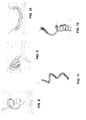
Figur 1 nach Implantation; und - Fig. 3 bis 12
- weitere Beispiele für einen Zuleitungsabschnitt mit veränderter Form.
- Fig. 1
- an electrode lead according to the invention before implantation;
- Fig. 2
- the electrode line off
FIG. 1 after implantation; and - Fig. 3 to 12
- Further examples of a lead portion with a changed shape.
In
In
Die helixförmige Wendel kann dabei entstehen, indem die gesamte Elektrodenleitung samt in ihr befindlichem Zuleitungsabschnitt gewendelt wird oder aber bevorzugt eine Wendel der Zuleitung innerhalb der äußeren Hülle der Elektrodenleitung entsteht, wobei sich dann die äußere Hülle (270) ballonförmig aufweitet. Letzteres ist in
Die Induktivität der vom formveränderlichen Zuleitungsabschnitt gebildeten Helix-Wendel beträgt im gezeigten Beispiel etwa 1 µH, d.h. die Wendel hat ca. 30 Windungen auf einer Länge von 10 cm mit einem Durchmesser von 1,2 cm. Zusammen mit der Gewebeimpedanz ergibt sich so ein Spannungsteiler, die die Elektrodenerwärmung mindestens um den Faktor 2 reduziert.In the example shown, the inductance of the helix coil formed by the variable-shape lead portion is about 1 μH, ie the coil has about 30 turns on a length of 10 cm with a diameter of 1.2 cm. Together with the tissue impedance This results in a voltage divider that reduces the electrode heating by at least a factor of 2.
Die so gebildete Elektrodenleitung ist MRT-tauglich und besitzt an den qualitätsrelevanten Fügestellen keine Abweichungen von herkömmlichen Elektrodenleitungen. Ebenso werden keine zusätzlichen elektronischen Bauelemente in der Elektrode benötigt.The electrode line thus formed is MRI-compatible and has no deviations from conventional electrode lines at the quality-relevant joints. Likewise, no additional electronic components in the electrode are needed.
Ausführungen zur veränderten Form des Zuleitungsabschnitts nach Implantation:Versions of the modified form of the lead section after implantation:
Die Kräuselung (Stauchung, Unterbringung einer größeren Länge auf kleinem Raum) erfolgt bei oder nach Implantation. Beispielsweise nimmt der formveränderliche Zuleitungsabschnitt bei Entfernung eines Mandrins eine vorgeformte/voreingeprägte Form an. Alternativ oder zusätzlich findet dies durch Wärmeeinfluss statt (Memory shape) - d.h. durch die Eigenwärme des Körpers oder Erwärmen des Mandrins.The crimping (compression, housing a greater length in a small space) takes place during or after implantation. For example, upon removal of a stylet, the conformable lead portion assumes a preformed / pre-punched shape. Alternatively or additionally, this takes place by heat influence (memory shape) - i. due to the body heat or warming of the mandrin.
Die Kräuselung ist bevorzugt im distalen Bereich, ggf. zusätzlich im proximalen Bereich oder auch nur im proximalen Bereich, ausgebildet.The crimp is preferably formed in the distal region, if appropriate additionally in the proximal region or else only in the proximal region.
In einer weiteren Ausführung sind mehrere gekräuselte Bereiche entlang der Elektrodenleitung ausgeprägt. Diese sind bevorzugt an die lokalen anatomischen Gegebenheiten angepasst, z.B. in der oberen Hohlvene eine Form, im Vorhof eine zweite Form und im Ventrikel eine dritte Form.In a further embodiment, a plurality of crimped areas along the electrode line are pronounced. These are preferably adapted to the local anatomical conditions, e.g. a form in the superior vena cava, a second form in the atrium, and a third form in the ventricle.
Die veränderte Form kann verschiedene Ausprägungen haben:The changed form can have different characteristics:
Diese Formen gehen im Wesentlichen von zwei Grundformen aus und darauf aufbauend (durch Kombinatorik/Verschachtelung) entsteht eine Vielfalt weiterer Formen, wie sie in den
Die Grundformen sind im Wesentlichen:
- Helix, siehe
Figur 3 , und - Mäander, siehe
Figur 4 .
- Helix, see
FIG. 3 , and - Meander, see
FIG. 4 ,
Varianten des Mäander und der Helix sind in
- Mäander als Torus, siehe
Figur 6 ; - Helix als Torus, siehe
Figur 7 ; - Mäander als Helix, siehe
Figur 8 ; - Mäander geformt, siehe
Figur 9 ; - Helix flachgedrückt, siehe
Figur 10 ; - Helix als Mäander, siehe
Figur 11 ; - Helix als Helix, siehe
Figur 12 .
- Meandering as torus, see
FIG. 6 ; - Helix as a torus, see
FIG. 7 ; - Meander as a helix, see
FIG. 8 ; - Meander shaped, see
FIG. 9 ; - Helix flattened, see
FIG. 10 ; - Helix as a meander, see
FIG. 11 ; - Helix as a helix, see
FIG. 12 ,
Die Elektrodenleitungen für diese gekräuselten Ausführungen haben bevorzugt eine Dicke von weniger als 5 F.The electrode leads for these crimped designs preferably have a thickness of less than 5F.
Claims (15)
dadurch gekennzeichnet,
dass die elektrische Zuleitung ausgebildet ist, nach Implantation der Elektrodenleitung in einem formveränderlichen Zuleitungsabschnitt eine solche veränderte Form einzunehmen, die in dem formveränderlichen Zuleitungsabschnitt nach Verformung eine höhere Induktivität als vor der Verformung bewirkt, wobei die Induktivität mindestens 0,1 µH beträgt.An implantable longitudinal electrode lead comprising an electrode body, at least one electrode pole connected to the electrode body, a terminal and an electrical lead electrically connected to the electrode pole and extending from the electrode pole to the terminal at a proximal end of the electrode lead,
characterized,
that the electrical supply line is formed after implantation of the electrode line in a form variable supply line to take such a modified form, which causes a higher inductance in the form variable supply section after deformation than before the deformation, wherein the inductance is at least 0.1 uH.
dadurch gekennzeichnet,
dass die elektrische Zuleitung ausgebildet ist, nach Implantation der Elektrodenleitung in einem formveränderlichen Zuleitungsabschnitt eine gegenüber ihrer ursprünglichen Form veränderte Form einzunehmen und die Zuleitung außerdem so ausgebildet und innerhalb der Hülle so angeordnet ist, dass die Zuleitung in ihrem formveränderlichen Zuleitungsabschnitt relativ zur äußeren Hülle und innerhalb der äußeren Hülle formveränderlich ist.An implantable longitudinal electrode lead comprising an electrode body, at least one electrode pole connected to the electrode body, a terminal and an electrical lead electrically connected to the electrode pole and extending from the electrode pole to the terminal at a proximal end of the electrode lead, the implantable electrode lead an outer shell, within which the supply line is arranged,
characterized,
that the electrical supply line is formed after implantation of the electrode line in a form variable supply line section changed shape compared to their original form and the supply line is also designed and disposed within the shell so that the supply line in its form variable supply line relative to the outer shell and inside the outer shell is dimensionally variable.
Applications Claiming Priority (1)
| Application Number | Priority Date | Filing Date | Title |
|---|---|---|---|
| US201161568182P | 2011-12-08 | 2011-12-08 |
Publications (2)
| Publication Number | Publication Date |
|---|---|
| EP2602000A1 true EP2602000A1 (en) | 2013-06-12 |
| EP2602000B1 EP2602000B1 (en) | 2016-06-01 |
Family
ID=47227563
Family Applications (1)
| Application Number | Title | Priority Date | Filing Date |
|---|---|---|---|
| EP12192386.6A Not-in-force EP2602000B1 (en) | 2011-12-08 | 2012-11-13 | Implantable electrode lead |
Country Status (3)
| Country | Link |
|---|---|
| US (1) | US8942820B2 (en) |
| EP (1) | EP2602000B1 (en) |
| CN (1) | CN103157181B (en) |
Families Citing this family (6)
| Publication number | Priority date | Publication date | Assignee | Title |
|---|---|---|---|---|
| US10792490B2 (en) | 2013-11-12 | 2020-10-06 | Medtronic, Inc. | Open channel implant tools and implant techniques utilizing such tools |
| EP3204107B1 (en) * | 2014-10-06 | 2019-09-25 | Med-El Elektromedizinische Geraete GmbH | Modified electrode lead for cochlear implants |
| CN107249486B (en) * | 2014-11-09 | 2021-07-30 | 森索医疗实验室有限公司 | Customized three-dimensional shaping of surgical guides |
| US11083491B2 (en) | 2014-12-09 | 2021-08-10 | Medtronic, Inc. | Extravascular implant tools utilizing a bore-in mechanism and implant techniques using such tools |
| US10349978B2 (en) | 2014-12-18 | 2019-07-16 | Medtronic, Inc. | Open channel implant tool with additional lumen and implant techniques utilizing such tools |
| WO2021114120A1 (en) * | 2019-12-11 | 2021-06-17 | 中国科学院深圳先进技术研究院 | Self-stretching recording electrode, and preparation method and implantation method therefor |
Citations (4)
| Publication number | Priority date | Publication date | Assignee | Title |
|---|---|---|---|---|
| US20080161886A1 (en) * | 2006-06-08 | 2008-07-03 | Greatbatch Ltd. | Tank filters adaptable for placement with a guide wire, in series with the lead wires or circuits of active medical devices to enhance mri compatibility |
| US20110087299A1 (en) * | 2009-10-08 | 2011-04-14 | Masoud Ameri | Medical device lead including a flared conductive coil |
| US20110208280A1 (en) * | 2010-02-19 | 2011-08-25 | Yingbo Li | Lead including conductors configured for reduced mri-induced currents |
| US20110270362A1 (en) * | 2010-04-28 | 2011-11-03 | Medtronic, Inc. | Active circuit mri/emi protection powered by interfering energy for a medical stimulation lead and device |
Family Cites Families (3)
| Publication number | Priority date | Publication date | Assignee | Title |
|---|---|---|---|---|
| US6584362B1 (en) * | 2000-08-30 | 2003-06-24 | Cardiac Pacemakers, Inc. | Leads for pacing and/or sensing the heart from within the coronary veins |
| US6782293B2 (en) * | 2001-09-14 | 2004-08-24 | Zoll Medical Corporation | Defibrillation electrode assembly including CPR pad |
| CA2722982A1 (en) * | 2008-05-02 | 2009-11-05 | Medtronic, Inc. | Self expanding electrode cuff |
-
2012
- 2012-11-12 CN CN201210449417.7A patent/CN103157181B/en not_active Expired - Fee Related
- 2012-11-13 EP EP12192386.6A patent/EP2602000B1/en not_active Not-in-force
- 2012-11-15 US US13/677,310 patent/US8942820B2/en not_active Expired - Fee Related
Patent Citations (4)
| Publication number | Priority date | Publication date | Assignee | Title |
|---|---|---|---|---|
| US20080161886A1 (en) * | 2006-06-08 | 2008-07-03 | Greatbatch Ltd. | Tank filters adaptable for placement with a guide wire, in series with the lead wires or circuits of active medical devices to enhance mri compatibility |
| US20110087299A1 (en) * | 2009-10-08 | 2011-04-14 | Masoud Ameri | Medical device lead including a flared conductive coil |
| US20110208280A1 (en) * | 2010-02-19 | 2011-08-25 | Yingbo Li | Lead including conductors configured for reduced mri-induced currents |
| US20110270362A1 (en) * | 2010-04-28 | 2011-11-03 | Medtronic, Inc. | Active circuit mri/emi protection powered by interfering energy for a medical stimulation lead and device |
Also Published As
| Publication number | Publication date |
|---|---|
| CN103157181A (en) | 2013-06-19 |
| EP2602000B1 (en) | 2016-06-01 |
| CN103157181B (en) | 2015-07-22 |
| US8942820B2 (en) | 2015-01-27 |
| US20130150932A1 (en) | 2013-06-13 |
Similar Documents
| Publication | Publication Date | Title |
|---|---|---|
| EP2602000B1 (en) | Implantable electrode lead | |
| US8688236B2 (en) | Medical lead coil conductor with spacer element | |
| US8335572B2 (en) | Medical device lead including a flared conductive coil | |
| US8306630B2 (en) | Apparatus to selectively increase medical device lead inner conductor inductance | |
| EP1923094B1 (en) | Electrode catheter for intervention purposes | |
| EP3284516B1 (en) | Implant and method for the identification of an electrode lead | |
| US8521304B2 (en) | MRI compatible implantable lead with a distributed band stop filter | |
| EP2110154B1 (en) | Device for reducing the interference susceptibility of elongate impants | |
| US20100331942A1 (en) | Mri compatible implantable medical lead and method of making same | |
| EP1285678B1 (en) | Single electrode lead for pacemaker systems | |
| EP2985053A1 (en) | Implantable electrical line | |
| EP2110156B1 (en) | Field decoupling element for use with an implantable lead and implantable medical device | |
| EP2465569B1 (en) | Implantable device | |
| EP2478933A2 (en) | Implantable device | |
| EP2465573B1 (en) | Implantable device | |
| EP2446922B1 (en) | Implantable conductors with additional, field decoupling conductors | |
| EP2985054B1 (en) | Implantable device with electrical filter | |
| EP2848282B1 (en) | Implantable device | |
| EP2853288B1 (en) | Implantable device and production method for an implantable device | |
| EP2143463A1 (en) | Shock electrode line | |
| EP2465570B1 (en) | Implantable device | |
| EP3009165A1 (en) | Implantable electrical lead | |
| US20110144722A1 (en) | Mri-compatible implantable lead with improved lc resonant component | |
| DE102009002707A1 (en) | Electrode element, electrode line with an electrode element and manufacturing method of an electrode line | |
| EP3025756A2 (en) | Electrode extension integrated in an active implant |
Legal Events
| Date | Code | Title | Description |
|---|---|---|---|
| PUAI | Public reference made under article 153(3) epc to a published international application that has entered the european phase |
Free format text: ORIGINAL CODE: 0009012 |
|
| AK | Designated contracting states |
Kind code of ref document: A1 Designated state(s): AL AT BE BG CH CY CZ DE DK EE ES FI FR GB GR HR HU IE IS IT LI LT LU LV MC MK MT NL NO PL PT RO RS SE SI SK SM TR |
|
| AX | Request for extension of the european patent |
Extension state: BA ME |
|
| 17P | Request for examination filed |
Effective date: 20131129 |
|
| RBV | Designated contracting states (corrected) |
Designated state(s): AL AT BE BG CH CY CZ DE DK EE ES FI FR GB GR HR HU IE IS IT LI LT LU LV MC MK MT NL NO PL PT RO RS SE SI SK SM TR |
|
| REG | Reference to a national code |
Ref country code: DE Ref legal event code: R079 Ref document number: 502012007288 Country of ref document: DE Free format text: PREVIOUS MAIN CLASS: A61N0001000000 Ipc: A61N0001050000 |
|
| RIC1 | Information provided on ipc code assigned before grant |
Ipc: A61N 1/05 20060101AFI20151120BHEP Ipc: A61N 1/08 20060101ALN20151120BHEP |
|
| GRAP | Despatch of communication of intention to grant a patent |
Free format text: ORIGINAL CODE: EPIDOSNIGR1 |
|
| INTG | Intention to grant announced |
Effective date: 20160115 |
|
| GRAS | Grant fee paid |
Free format text: ORIGINAL CODE: EPIDOSNIGR3 |
|
| GRAA | (expected) grant |
Free format text: ORIGINAL CODE: 0009210 |
|
| AK | Designated contracting states |
Kind code of ref document: B1 Designated state(s): AL AT BE BG CH CY CZ DE DK EE ES FI FR GB GR HR HU IE IS IT LI LT LU LV MC MK MT NL NO PL PT RO RS SE SI SK SM TR |
|
| REG | Reference to a national code |
Ref country code: GB Ref legal event code: FG4D Free format text: NOT ENGLISH |
|
| REG | Reference to a national code |
Ref country code: CH Ref legal event code: EP Ref country code: AT Ref legal event code: REF Ref document number: 803496 Country of ref document: AT Kind code of ref document: T Effective date: 20160615 |
|
| REG | Reference to a national code |
Ref country code: IE Ref legal event code: FG4D Free format text: LANGUAGE OF EP DOCUMENT: GERMAN |
|
| REG | Reference to a national code |
Ref country code: DE Ref legal event code: R096 Ref document number: 502012007288 Country of ref document: DE |
|
| REG | Reference to a national code |
Ref country code: LT Ref legal event code: MG4D |
|
| REG | Reference to a national code |
Ref country code: NL Ref legal event code: MP Effective date: 20160601 |
|
| PG25 | Lapsed in a contracting state [announced via postgrant information from national office to epo] |
Ref country code: NO Free format text: LAPSE BECAUSE OF FAILURE TO SUBMIT A TRANSLATION OF THE DESCRIPTION OR TO PAY THE FEE WITHIN THE PRESCRIBED TIME-LIMIT Effective date: 20160901 Ref country code: FI Free format text: LAPSE BECAUSE OF FAILURE TO SUBMIT A TRANSLATION OF THE DESCRIPTION OR TO PAY THE FEE WITHIN THE PRESCRIBED TIME-LIMIT Effective date: 20160601 Ref country code: LT Free format text: LAPSE BECAUSE OF FAILURE TO SUBMIT A TRANSLATION OF THE DESCRIPTION OR TO PAY THE FEE WITHIN THE PRESCRIBED TIME-LIMIT Effective date: 20160601 |
|
| PG25 | Lapsed in a contracting state [announced via postgrant information from national office to epo] |
Ref country code: ES Free format text: LAPSE BECAUSE OF FAILURE TO SUBMIT A TRANSLATION OF THE DESCRIPTION OR TO PAY THE FEE WITHIN THE PRESCRIBED TIME-LIMIT Effective date: 20160601 Ref country code: SE Free format text: LAPSE BECAUSE OF FAILURE TO SUBMIT A TRANSLATION OF THE DESCRIPTION OR TO PAY THE FEE WITHIN THE PRESCRIBED TIME-LIMIT Effective date: 20160601 Ref country code: LV Free format text: LAPSE BECAUSE OF FAILURE TO SUBMIT A TRANSLATION OF THE DESCRIPTION OR TO PAY THE FEE WITHIN THE PRESCRIBED TIME-LIMIT Effective date: 20160601 Ref country code: HR Free format text: LAPSE BECAUSE OF FAILURE TO SUBMIT A TRANSLATION OF THE DESCRIPTION OR TO PAY THE FEE WITHIN THE PRESCRIBED TIME-LIMIT Effective date: 20160601 Ref country code: NL Free format text: LAPSE BECAUSE OF FAILURE TO SUBMIT A TRANSLATION OF THE DESCRIPTION OR TO PAY THE FEE WITHIN THE PRESCRIBED TIME-LIMIT Effective date: 20160601 Ref country code: GR Free format text: LAPSE BECAUSE OF FAILURE TO SUBMIT A TRANSLATION OF THE DESCRIPTION OR TO PAY THE FEE WITHIN THE PRESCRIBED TIME-LIMIT Effective date: 20160902 Ref country code: RS Free format text: LAPSE BECAUSE OF FAILURE TO SUBMIT A TRANSLATION OF THE DESCRIPTION OR TO PAY THE FEE WITHIN THE PRESCRIBED TIME-LIMIT Effective date: 20160601 |
|
| PG25 | Lapsed in a contracting state [announced via postgrant information from national office to epo] |
Ref country code: CZ Free format text: LAPSE BECAUSE OF FAILURE TO SUBMIT A TRANSLATION OF THE DESCRIPTION OR TO PAY THE FEE WITHIN THE PRESCRIBED TIME-LIMIT Effective date: 20160601 Ref country code: RO Free format text: LAPSE BECAUSE OF FAILURE TO SUBMIT A TRANSLATION OF THE DESCRIPTION OR TO PAY THE FEE WITHIN THE PRESCRIBED TIME-LIMIT Effective date: 20160601 Ref country code: IS Free format text: LAPSE BECAUSE OF FAILURE TO SUBMIT A TRANSLATION OF THE DESCRIPTION OR TO PAY THE FEE WITHIN THE PRESCRIBED TIME-LIMIT Effective date: 20161001 Ref country code: SK Free format text: LAPSE BECAUSE OF FAILURE TO SUBMIT A TRANSLATION OF THE DESCRIPTION OR TO PAY THE FEE WITHIN THE PRESCRIBED TIME-LIMIT Effective date: 20160601 Ref country code: EE Free format text: LAPSE BECAUSE OF FAILURE TO SUBMIT A TRANSLATION OF THE DESCRIPTION OR TO PAY THE FEE WITHIN THE PRESCRIBED TIME-LIMIT Effective date: 20160601 Ref country code: IT Free format text: LAPSE BECAUSE OF FAILURE TO SUBMIT A TRANSLATION OF THE DESCRIPTION OR TO PAY THE FEE WITHIN THE PRESCRIBED TIME-LIMIT Effective date: 20160601 |
|
| PG25 | Lapsed in a contracting state [announced via postgrant information from national office to epo] |
Ref country code: PT Free format text: LAPSE BECAUSE OF FAILURE TO SUBMIT A TRANSLATION OF THE DESCRIPTION OR TO PAY THE FEE WITHIN THE PRESCRIBED TIME-LIMIT Effective date: 20161003 Ref country code: PL Free format text: LAPSE BECAUSE OF FAILURE TO SUBMIT A TRANSLATION OF THE DESCRIPTION OR TO PAY THE FEE WITHIN THE PRESCRIBED TIME-LIMIT Effective date: 20160601 Ref country code: BE Free format text: LAPSE BECAUSE OF NON-PAYMENT OF DUE FEES Effective date: 20161130 Ref country code: SM Free format text: LAPSE BECAUSE OF FAILURE TO SUBMIT A TRANSLATION OF THE DESCRIPTION OR TO PAY THE FEE WITHIN THE PRESCRIBED TIME-LIMIT Effective date: 20160601 |
|
| REG | Reference to a national code |
Ref country code: DE Ref legal event code: R097 Ref document number: 502012007288 Country of ref document: DE |
|
| PLBE | No opposition filed within time limit |
Free format text: ORIGINAL CODE: 0009261 |
|
| STAA | Information on the status of an ep patent application or granted ep patent |
Free format text: STATUS: NO OPPOSITION FILED WITHIN TIME LIMIT |
|
| 26N | No opposition filed |
Effective date: 20170302 |
|
| PG25 | Lapsed in a contracting state [announced via postgrant information from national office to epo] |
Ref country code: DK Free format text: LAPSE BECAUSE OF FAILURE TO SUBMIT A TRANSLATION OF THE DESCRIPTION OR TO PAY THE FEE WITHIN THE PRESCRIBED TIME-LIMIT Effective date: 20160601 Ref country code: SI Free format text: LAPSE BECAUSE OF FAILURE TO SUBMIT A TRANSLATION OF THE DESCRIPTION OR TO PAY THE FEE WITHIN THE PRESCRIBED TIME-LIMIT Effective date: 20160601 |
|
| GBPC | Gb: european patent ceased through non-payment of renewal fee |
Effective date: 20161113 |
|
| REG | Reference to a national code |
Ref country code: FR Ref legal event code: ST Effective date: 20170731 |
|
| PG25 | Lapsed in a contracting state [announced via postgrant information from national office to epo] |
Ref country code: LU Free format text: LAPSE BECAUSE OF NON-PAYMENT OF DUE FEES Effective date: 20161130 |
|
| PG25 | Lapsed in a contracting state [announced via postgrant information from national office to epo] |
Ref country code: FR Free format text: LAPSE BECAUSE OF NON-PAYMENT OF DUE FEES Effective date: 20161130 |
|
| PG25 | Lapsed in a contracting state [announced via postgrant information from national office to epo] |
Ref country code: GB Free format text: LAPSE BECAUSE OF NON-PAYMENT OF DUE FEES Effective date: 20161113 |
|
| PGFP | Annual fee paid to national office [announced via postgrant information from national office to epo] |
Ref country code: DE Payment date: 20171127 Year of fee payment: 6 |
|
| REG | Reference to a national code |
Ref country code: BE Ref legal event code: MM Effective date: 20161130 |
|
| PGFP | Annual fee paid to national office [announced via postgrant information from national office to epo] |
Ref country code: IE Payment date: 20171123 Year of fee payment: 6 Ref country code: CH Payment date: 20171124 Year of fee payment: 6 |
|
| PG25 | Lapsed in a contracting state [announced via postgrant information from national office to epo] |
Ref country code: HU Free format text: LAPSE BECAUSE OF FAILURE TO SUBMIT A TRANSLATION OF THE DESCRIPTION OR TO PAY THE FEE WITHIN THE PRESCRIBED TIME-LIMIT; INVALID AB INITIO Effective date: 20121113 Ref country code: CY Free format text: LAPSE BECAUSE OF FAILURE TO SUBMIT A TRANSLATION OF THE DESCRIPTION OR TO PAY THE FEE WITHIN THE PRESCRIBED TIME-LIMIT Effective date: 20160601 |
|
| PG25 | Lapsed in a contracting state [announced via postgrant information from national office to epo] |
Ref country code: MK Free format text: LAPSE BECAUSE OF FAILURE TO SUBMIT A TRANSLATION OF THE DESCRIPTION OR TO PAY THE FEE WITHIN THE PRESCRIBED TIME-LIMIT Effective date: 20160601 Ref country code: TR Free format text: LAPSE BECAUSE OF FAILURE TO SUBMIT A TRANSLATION OF THE DESCRIPTION OR TO PAY THE FEE WITHIN THE PRESCRIBED TIME-LIMIT Effective date: 20160601 Ref country code: MC Free format text: LAPSE BECAUSE OF FAILURE TO SUBMIT A TRANSLATION OF THE DESCRIPTION OR TO PAY THE FEE WITHIN THE PRESCRIBED TIME-LIMIT Effective date: 20160601 |
|
| PG25 | Lapsed in a contracting state [announced via postgrant information from national office to epo] |
Ref country code: BG Free format text: LAPSE BECAUSE OF FAILURE TO SUBMIT A TRANSLATION OF THE DESCRIPTION OR TO PAY THE FEE WITHIN THE PRESCRIBED TIME-LIMIT Effective date: 20160601 |
|
| PG25 | Lapsed in a contracting state [announced via postgrant information from national office to epo] |
Ref country code: MT Free format text: LAPSE BECAUSE OF FAILURE TO SUBMIT A TRANSLATION OF THE DESCRIPTION OR TO PAY THE FEE WITHIN THE PRESCRIBED TIME-LIMIT Effective date: 20160601 |
|
| PG25 | Lapsed in a contracting state [announced via postgrant information from national office to epo] |
Ref country code: AL Free format text: LAPSE BECAUSE OF FAILURE TO SUBMIT A TRANSLATION OF THE DESCRIPTION OR TO PAY THE FEE WITHIN THE PRESCRIBED TIME-LIMIT Effective date: 20160601 |
|
| REG | Reference to a national code |
Ref country code: AT Ref legal event code: MM01 Ref document number: 803496 Country of ref document: AT Kind code of ref document: T Effective date: 20171113 |
|
| PG25 | Lapsed in a contracting state [announced via postgrant information from national office to epo] |
Ref country code: AT Free format text: LAPSE BECAUSE OF NON-PAYMENT OF DUE FEES Effective date: 20171113 |
|
| REG | Reference to a national code |
Ref country code: DE Ref legal event code: R119 Ref document number: 502012007288 Country of ref document: DE |
|
| REG | Reference to a national code |
Ref country code: CH Ref legal event code: PL |
|
| REG | Reference to a national code |
Ref country code: IE Ref legal event code: MM4A |
|
| PG25 | Lapsed in a contracting state [announced via postgrant information from national office to epo] |
Ref country code: LI Free format text: LAPSE BECAUSE OF NON-PAYMENT OF DUE FEES Effective date: 20181130 Ref country code: CH Free format text: LAPSE BECAUSE OF NON-PAYMENT OF DUE FEES Effective date: 20181130 |
|
| PG25 | Lapsed in a contracting state [announced via postgrant information from national office to epo] |
Ref country code: DE Free format text: LAPSE BECAUSE OF NON-PAYMENT OF DUE FEES Effective date: 20190601 Ref country code: IE Free format text: LAPSE BECAUSE OF NON-PAYMENT OF DUE FEES Effective date: 20181113 |