EP2601901A1 - Ultrasound therapy device - Google Patents
Ultrasound therapy device Download PDFInfo
- Publication number
- EP2601901A1 EP2601901A1 EP12763619.9A EP12763619A EP2601901A1 EP 2601901 A1 EP2601901 A1 EP 2601901A1 EP 12763619 A EP12763619 A EP 12763619A EP 2601901 A1 EP2601901 A1 EP 2601901A1
- Authority
- EP
- European Patent Office
- Prior art keywords
- tube member
- handle
- path
- probe
- unit
- Prior art date
- Legal status (The legal status is an assumption and is not a legal conclusion. Google has not performed a legal analysis and makes no representation as to the accuracy of the status listed.)
- Granted
Links
Images




Classifications
-
- A—HUMAN NECESSITIES
- A61—MEDICAL OR VETERINARY SCIENCE; HYGIENE
- A61N—ELECTROTHERAPY; MAGNETOTHERAPY; RADIATION THERAPY; ULTRASOUND THERAPY
- A61N7/00—Ultrasound therapy
-
- A—HUMAN NECESSITIES
- A61—MEDICAL OR VETERINARY SCIENCE; HYGIENE
- A61B—DIAGNOSIS; SURGERY; IDENTIFICATION
- A61B17/00—Surgical instruments, devices or methods
- A61B17/32—Surgical cutting instruments
- A61B17/320068—Surgical cutting instruments using mechanical vibrations, e.g. ultrasonic
- A61B17/320092—Surgical cutting instruments using mechanical vibrations, e.g. ultrasonic with additional movable means for clamping or cutting tissue, e.g. with a pivoting jaw
-
- A—HUMAN NECESSITIES
- A61—MEDICAL OR VETERINARY SCIENCE; HYGIENE
- A61B—DIAGNOSIS; SURGERY; IDENTIFICATION
- A61B17/00—Surgical instruments, devices or methods
- A61B17/32—Surgical cutting instruments
- A61B17/320068—Surgical cutting instruments using mechanical vibrations, e.g. ultrasonic
- A61B2017/320084—Irrigation sleeves
-
- A—HUMAN NECESSITIES
- A61—MEDICAL OR VETERINARY SCIENCE; HYGIENE
- A61B—DIAGNOSIS; SURGERY; IDENTIFICATION
- A61B17/00—Surgical instruments, devices or methods
- A61B17/32—Surgical cutting instruments
- A61B17/320068—Surgical cutting instruments using mechanical vibrations, e.g. ultrasonic
- A61B17/320092—Surgical cutting instruments using mechanical vibrations, e.g. ultrasonic with additional movable means for clamping or cutting tissue, e.g. with a pivoting jaw
- A61B2017/320093—Surgical cutting instruments using mechanical vibrations, e.g. ultrasonic with additional movable means for clamping or cutting tissue, e.g. with a pivoting jaw additional movable means performing cutting operation
-
- A—HUMAN NECESSITIES
- A61—MEDICAL OR VETERINARY SCIENCE; HYGIENE
- A61B—DIAGNOSIS; SURGERY; IDENTIFICATION
- A61B17/00—Surgical instruments, devices or methods
- A61B17/32—Surgical cutting instruments
- A61B17/320068—Surgical cutting instruments using mechanical vibrations, e.g. ultrasonic
- A61B17/320092—Surgical cutting instruments using mechanical vibrations, e.g. ultrasonic with additional movable means for clamping or cutting tissue, e.g. with a pivoting jaw
- A61B2017/320095—Surgical cutting instruments using mechanical vibrations, e.g. ultrasonic with additional movable means for clamping or cutting tissue, e.g. with a pivoting jaw with sealing or cauterizing means
-
- A—HUMAN NECESSITIES
- A61—MEDICAL OR VETERINARY SCIENCE; HYGIENE
- A61B—DIAGNOSIS; SURGERY; IDENTIFICATION
- A61B2217/00—General characteristics of surgical instruments
- A61B2217/002—Auxiliary appliance
- A61B2217/005—Auxiliary appliance with suction drainage system
-
- A—HUMAN NECESSITIES
- A61—MEDICAL OR VETERINARY SCIENCE; HYGIENE
- A61B—DIAGNOSIS; SURGERY; IDENTIFICATION
- A61B2217/00—General characteristics of surgical instruments
- A61B2217/002—Auxiliary appliance
- A61B2217/007—Auxiliary appliance with irrigation system
-
- A—HUMAN NECESSITIES
- A61—MEDICAL OR VETERINARY SCIENCE; HYGIENE
- A61B—DIAGNOSIS; SURGERY; IDENTIFICATION
- A61B2218/00—Details of surgical instruments, devices or methods for transferring non-mechanical forms of energy to or from the body
- A61B2218/001—Details of surgical instruments, devices or methods for transferring non-mechanical forms of energy to or from the body having means for irrigation and/or aspiration of substances to and/or from the surgical site
- A61B2218/002—Irrigation
-
- A—HUMAN NECESSITIES
- A61—MEDICAL OR VETERINARY SCIENCE; HYGIENE
- A61B—DIAGNOSIS; SURGERY; IDENTIFICATION
- A61B2218/00—Details of surgical instruments, devices or methods for transferring non-mechanical forms of energy to or from the body
- A61B2218/001—Details of surgical instruments, devices or methods for transferring non-mechanical forms of energy to or from the body having means for irrigation and/or aspiration of substances to and/or from the surgical site
- A61B2218/007—Aspiration
Definitions
- the present invention relates to an ultrasonic treatment device (ultrasonic surgical apparatus) configured to perform an ultrasonic treatment (ultrasonic surgery) including ultrasonic suction and ultrasonic cutting-and-coagulation.
- Patent Literature 1 discloses an ultrasonic suction device which includes an ultrasonic vibrator (ultrasonic oscillator), and a horn configured to transmit ultrasonic vibration generated by the ultrasonic vibrator from a proximal end to a distal end.
- an ultrasonic suction device (ultrasonic aspiration device)
- an suction path is extended inside the horn along a longitudinal axis.
- the suction path (aspiration path) is bent at a bending position to a proximal direction side of the horn, and extended from the bending position toward an outer peripheral direction.
- a suction pipe (aspiration pipe) is connected to the suction path on an outer peripheral portion of the ultrasonic vibrator.
- ultrasonic suction is conducted by a distal surface of the ultrasonically vibrating horn with using a physical phenomenon called "cavitation".
- a pressure periodically varies near the distal surface of the horn.
- the pressure near the distal surface is lower than a saturated vapor pressure for a short time due to a variation in pressure, small air bubbles (cavities) are produced in a liquid in a body cavity or a liquid supplied to a position near a treatment position (surgical target) of a body tissue from the ultrasonic treatment device.
- a force which acts when the pressure near the distal surface is increased (compressed), annihilates the produced air bubbles.
- the above-described physical phenomenon is called a "cavitation phenomenon".
- a body tissue having no elasticity, like a liver cell, is shattered (crushed) and emulsified by impact energy at the time of annihilation of the air bubbles.
- the shattered and emulsified body tissue is suctioned (aspirated) and collected from a suction opening (aspiration opening) at the distal end of the horn through the suction path and an inside of the suction pipe.
- a body tissue having high elasticity like a blood vessel, is difficult to shatter since it absorbs impact shock, and thereby body tissues are selectively shattered.
- Patent Literature 2 discloses an ultrasonic cutting-and-coagulation device including an ultrasonic vibrator (ultrasonic oscillator), and a non-hollow (columnar) probe configured to transmit ultrasonic vibration generated by the ultrasonic vibrator from a proximal end to a distal end.
- This ultrasonic cutting-and-coagulation device includes an elongated sheath into which the probe is inserted, and a jaw openable/closable with respect to a distal end portion of the probe.
- the ultrasonic cutting-and-coagulation device includes a handle unit.
- a treatment unit including the probe, the sheath, and the jaw is coupled with a vibrator unit (oscillator unit) including the ultrasonic vibrator.
- the handle unit includes a fixed handle, and a movable handle openable/closable with respect to the fixed handle.
- a movable portion provided to the sheath, moves along the longitudinal axis.
- the jaw is opened/closed with respect to the distal end portion of the probe.
- An ultrasonic cutting-and-coagulation treatment is carried out by utilizing the ultrasonic vibration while gripping a body tissue such as a blood vessel between the distal end portion of the probe and the jaw.
- a body tissue such as a blood vessel
- the probe ultrasonically vibrates in a state that a body tissue such as a blood vessel is gripped between the distal end portion of the probe and the jaw
- frictional heat is generated between the distal end portion of the probe and the body tissue.
- Cutting and coagulation of the body tissue are simultaneously performed between the distal end portion of the probe and the jaw by using the generated frictional heat.
- the distal end portion of the probe and the jaw are used as electrodes, and a bipolar treatment (bipolar surgery) using a high-frequency current is also carried out.
- an ultrasonic suction treatment in which a body tissue with no elasticity, such as a liver cell, is selectively shattered and emulsified by the cavitation and thereby the shattered body tissue is suctioned and collected.
- a body tissue with high elasticity such as a blood vessel, that is selectively left, is subjected to the ultrasonic cutting-and-coagulation treatment.
- the ultrasonic suction treatment and the ultrasonic cutting-and-coagulation treatment use different devices, the devices must be counterchanged in accordance with each treatment.
- a treatment device that can give both the ultrasonic suction treatment and the ultrasonic cutting-and-coagulation treatment.
- the devices are recombined. That is, a device counterchanging operation, a device recombining operation, and other operations are required in accordance with the respective treatments. Therefore, various problems occur, e.g., a reduction in continuity of an operation such as a surgical operation, a reduction in surgical efficiency, an increase in stress or fatigue of an operator (surgeon) due to prolongation of a procedure period (surgery time), an increased burden on a patient, and other problems. Therefore, a multifunctional medical treatment device (multifunctional surgical apparatus) that can give various medical treatments (surgical treatment) without counterchanging or recombining devices is demanded.
- the following ultrasonic treatment device can be considered. That is, in the ultrasonic cutting-and-coagulation device disclosed in Patent Literature 2, consideration will now be given to a situation where a hollow (cylindrical) probe in which a suction path (aspiration path) is provided from a distal end along a longitudinal axis is used in place of the non-hollow (columnar) probe.
- the suction path is extended along the longitudinal axis from an inside of the probe through an inside of a horn and an inside of an ultrasonic vibrator.
- the suction path is connected to a suction tube (aspiration tube) at a proximal end portion of the ultrasonic vibrator. Furthermore, the suction tube is extended to an outside of a vibrator case (oscillator case) of a vibrator unit. With such a configuration, a body tissue shattered and emulsified by the cavitation is suctioned and collected from a suction opening (aspiration opening) at a distal end of the probe through the suction path and an inside of the suction tube. Moreover, like the ultrasonic cutting-and-coagulation device disclosed in Patent Literature 2, an ultrasonic cutting-and-coagulation treatment is performed between the distal end portion of the probe and a jaw. Therefore, both the ultrasonic suction treatment and the ultrasonic cutting-and-coagulation treatment can be given without, e.g., counterchanging or recombining the devices.
- the vibrator unit is connected to one end of a cable in which an electrical signal line or the like, through which a current is supplied to the ultrasonic vibrator, is extended. Therefore, when the suction tube is connected to the vibrator unit in addition to the cable, a weight on a part to the proximal direction side of a handle unit is larger.
- An operator surgeon performs a treatment (surgery) while holding a fixed handle and a movable handle in the handle unit.
- the ultrasonic vibrator is not disposed (discarded), but is reused. Therefore, in the ultrasonic treatment device including the treatment unit (surgery unit), the handle unit, and the vibrator unit, the treatment unit and the handle unit are disposed after use, and the vibrator unit is reused. Therefore, when the suction path is provided in the ultrasonic vibrator, sterilization and cleaning are required after use. Further, the suction tube connected to the vibrator unit is disposed after use. Therefore, after use of the ultrasonic treatment device, the vibrator unit must be removed from the handle unit, and the suction tube must be removed from the vibrator unit.
- the vibrator unit In preparation of assembling the ultrasonic treatment device, the vibrator unit must be coupled with the handle unit, and the suction tube must be connected to the vibrator unit. As described above, when the suction tube is connected to the vibrator unit, the processing after use, the preparation of assembling, and so on become complicated.
- an object of the present invention to provide an ultrasonic treatment device which can perform ultrasonic suction and ultrasonic cutting-and-coagulation without effecting recombination and other operations, which has good balance of the center of gravity during a treatment, and which allows processing after use, preparation of assembly, and so on to be easily carried out.
- an ultrasonic treatment device which can perform ultrasonic suction and ultrasonic cutting-and-coagulation without effecting recombination and other operations, which has good balance of the center of gravity during a treatment, and which allows processing after use, preparation of assembly, and so on to be easily carried out, can be provided.
- FIG. 1 is a view showing an ultrasonic treatment device (ultrasonic surgical apparatus) 1 according to this embodiment.
- the ultrasonic treatment device 1 according to this embodiment is an ultrasonic suction device (ultrasonic aspiration device) configured to selectively shatter (crush) and resect (excise) a body tissue by cavitation produced due to ultrasonic vibration and configured to suction (aspirate) the resected body tissue.
- the ultrasonic treatment device 1 is also used as an ultrasonic cutting-and-coagulation device configured to carry out a cutting-and-coagulation treatment (cutting-and coagulation surgery) of a body tissue that is gripped between a distal end portion of a probe 5 (which will be described later) and a jaw 32 (which will be described later).
- the ultrasonic treatment device 1 includes a vibrator unit (oscillator unit) 2, a treatment unit (surgery unit) 3, and a handle unit 4.
- the treatment unit 3 includes a probe 5 that is extended along a longitudinal axis C.
- the vibrator unit 2 includes a vibrator case (oscillator case) 11. One end of a cable is connected to a proximal end of the vibrator case 11. The other end of the cable 6 is connected to a power supply unit 7.
- the power supply unit 7 includes an ultrasonic supply section 8, a high-frequency current supply section 9, and a control section 10.
- An input unit 20 such as a foot switch is connected to the control section 10 of the power supply unit 7.
- the input unit 20 includes a first input section 23A, a second input section 23B, and a third input section 23C.
- FIG. 2 is a view showing a configuration of the vibrator unit 2.
- an ultrasonic vibrator (ultrasonic oscillator) 12 including piezoelectric elements configured to convert an electric current into ultrasonic vibration is provided in the vibrator case 11.
- One end of each of electrical signal lines 13A and 13B is connected to the ultrasonic vibrator 12.
- the other end of each of the electrical signal lines 13A and 13B is connected to the ultrasonic supply section 8 in the power supply unit 7 through an inside of the cable 6.
- a horn 15 configured to increase an amplitude of the ultrasonic vibration is coupled to a distal direction side of the ultrasonic vibrator 12.
- the horn 15 is attached to the vibrator case 11, and it is electrically insulated from the vibrator case 11. Furthermore, a female screw portion 16 is formed in a distal end portion of the horn 15. Moreover, an electrical signal line 17 extended from the high-frequency current supply section 9 in the power supply unit 7 through the inside of the cable 6 is connected to the ultrasonic vibrator 12 in addition to the electrical signal lines 13A and 13B.
- FIG. 3 is a view showing a configuration of the probe 5.
- a male screw portion 19 is provided at a proximal direction side portion of the probe 5.
- the male screw portion 19 of the probe 5 is screwed into the female screw portion 16 of the horn 15, the probe 5 is attached to the horn 15.
- the ultrasonic vibration generated in the ultrasonic vibrator 12 is transmitted to a distal end of the probe 5 through the horn 15. That is, the ultrasonic vibration is transmitted from a proximal end to the distal end of the probe 5. It is to be noted that the ultrasonic vibration is longitudinal vibration, in which a vibration transmission direction coincides with a vibration direction.
- a probe-side current path of the high-frequency current is formed from the high-frequency current supply section 9 to a distal end portion of the probe 5 through the electrical signal line 17, the ultrasonic vibrator 12, and the horn 15.
- the probe-side current path is configured to transmit the high-frequency current between the high-frequency current supply section 9 and the distal end portion of the probe 5 along the longitudinal axis C.
- a hole-shaped portion 21 is extended in the probe 5 from the distal end portion of the probe 5 along the longitudinal axis C.
- the hole-shaped portion 21 is opened at an opening position Y1 located at the distal end portion of the probe 5.
- the hole-shaped portion 21 is defined by a hole defining surface 22 of the probe 5.
- a proximal end of the hole-shaped portion 21 is placed to the distal direction side of the proximal end of the probe 5. Therefore, a proximal direction side portion of the probe 5 is formed into a columnar shape (non-hollow).
- an opening hole 24 extended from an outer peripheral portion to the proximal end portion of the hole-shaped portion 21 in radial directions is provided.
- the handle unit 4 includes a cylindrical case 25 extended along the longitudinal axis C.
- the cylindrical case 25 is made of an insulating material.
- a fixed handle 26 is extended from the cylindrical case 25 toward a handle extending direction (a direction of an arrow A in FIG. 1 ) that is not parallel to the longitudinal axis C.
- the fixed handle 26 is provided to be inclined with respect to the longitudinal axis C.
- a movable handle 27 is pivotably attached to the cylindrical case 25.
- the movable handle 27 is be openable and closable with respect to the fixed handle 26 substantially in parallel with the longitudinal axis C.
- the movable handle 27 is placed to the distal direction side of the fixed handle 26.
- the vibrator unit 2 is coupled with the cylindrical case 25 from the proximal direction side.
- the treatment unit 3 is coupled with the cylindrical case 25 from the distal direction side.
- the treatment unit 3 includes a sheath portion 31 into which the probe 5 is inserted so that the probe 5 protrudes in the distal direction, and a jaw 32 which is pivotably attached to a distal end portion of the sheath portion 31.
- the jaw 32 is openable/closable with respect to the distal end portion of the probe 5.
- the handle unit 4 includes a rotating operation knob 29, which is a rotating operation section, coupled to the distal direction side of the cylindrical case 25.
- the rotating operation knob 29 is coupled with the cylindrical case 25 to be rotatable in periaxial directions.
- the treatment unit 3 rotates in one of the periaxial directions with respect to the cylindrical case 25.
- FIG. 4 is a view showing a configuration of an inside of the handle unit 4.
- the probe 5 and the sheath portion 31 are extended to an inside of the cylindrical case 25 through an inside of the rotating operation knob 29 along the longitudinal axis C.
- a first coupling region X1 in the cylindrical case 25 the proximal end of the probe 5 is attached to the horn 15. That is, the probe 5 is extended from the first coupling region X1 in the cylindrical case 25 toward the distal direction.
- a proximal end portion of the sheath portion 31 is coupled with the vibrator case 11.
- the treatment unit 3 is coupled with the vibrator unit 2.
- the sheath portion 31 includes a fixed cylindrical member 35 and a movable cylindrical member 36 which are coupled with the rotating operation knob 29.
- the fixed cylindrical member 35 and the movable cylindrical member 36 are provided along the longitudinal axis C.
- the fixed cylindrical member 35 is provided in a fixed state with respect to the rotating operation knob 29.
- the movable cylindrical member 36 is provided to be movable along the longitudinal axis C with respect to the rotating operation knob 29 and the fixed cylindrical member 35.
- the movable cylindrical member 36 is regulated so that it does not move in the periaxial directions with respect to the rotating operation knob 29.
- the fixed cylindrical member 35 and the movable cylindrical member 36 rotate integrally with the rotating operation knob 29 in the periaxial directions with respect to the cylindrical case 25. Additionally, the movable cylindrical member 36 can move along the longitudinal axis C with respect to the handle unit 4 and the probe 5.
- a proximal end of the fixed cylindrical member 35 is extended to the first coupling region X1.
- the probe 5 is supported by the fixed cylindrical member 35 through an insulating member 37.
- the probe 5 is prevented from coming into contact with the fixed cylindrical member 35, and the probe 5 is electrically insulated from the fixed cylindrical member 35 (the sheath portion 31).
- the probe 5 is fixed to the fixed cylindrical member 35 by using the insulating member 37.
- a rotary drive force of the rotating operation knob 29 is transmitted to the probe 5 through the fixed cylindrical member 35. Therefore, the probe 5 can rotate with respect to the cylindrical case 25 integrally with the rotating operation knob 29 and the fixed cylindrical member 35.
- an electrical connection ring 39 is provided to an outer peripheral direction side of the fixed cylindrical member 35.
- the electrical connection ring 39 is provided in a fixed state with respect to the cylindrical case 25. Furthermore, a distal end portion of the vibrator case 11 is engaged between the fixed cylindrical member 35 and the electrical connection ring 39. When the distal end portion of the vibrator case 11 is engaged between the fixed cylindrical member 35 and the electrical connection ring 39, the vibrator case 11 is coupled with the sheath portion 31 (the fixed cylindrical member 35).
- the cylindrical case 25 includes a planar portion 41 that is substantially parallel to a handle extending direction (a direction of an arrow A in each of FIG. 1 and FIG. 4 ).
- the planar portion 41 is provided on the side where the fixed handle 26 and the movable handle 27 are placed with the longitudinal axis C being at the center. Further, the planar portion 41 is placed to the distal direction side of the movable handle 27.
- Input buttons 42A and 42B as operation input sections are provided on the planar portion 41.
- an operation of an operator is input.
- switch portions 43A and 43B and an electrical circuit board 45 are provided to the proximal direction side of the planar portion 41. ON/OFF states of the switch portion 43A are changed over by an input operation using the input button 42A. Likewise, ON/OFF states of the switch portion 43B are changed over by an input operation using the input button 42B.
- an electrical connection ring 47 is provided in a fixed state with respect to the cylindrical case 25.
- the electrical connection ring 47 is placed to the outer peripheral direction side of the vibrator case 11. In a state that the vibrator case 11 is coupled with the sheath portion 31, the electrical connection ring 47 is in contact with the outer peripheral portion of the vibrator case 11.
- An input button 42C which is an operation input section, is provided on an outer peripheral portion of the cylindrical case 25.
- the input button 42C is provided on an opposite side of the side where the fixed handle 26 and the movable handle 27 are placed with the longitudinal axis C being at the center.
- an operation of an operator is input.
- a switch portion 43C and an electrical circuit board 49 are provided to an inner peripheral direction side of the input button 42C. ON/OFF states of the switch portion 43C are changed over by an input operation using the input button 42C.
- FIG. 5 is a view schematically showing an electrical connection state in the vibrator case 11.
- the electrical signal line 51A is electrically connected to the switch portion 43A through the electrical circuit board 45.
- the electrical signal line 51B is electrically connected to the switch portion 43B through the electrical circuit board 45.
- the electrical signal line 51C is electrically connected to the switch portion 43A and the switch portion 43B through the electrical circuit board 45.
- the electrical signal line 51C is a common line shared as a ground line of the switch portion 43A and the switch portion 43B.
- the electrical signal lines 51D and 51E are connected to the switch portion 43C.
- the electrical signal line 51E is used as a ground line of the switch portion 43C.
- the electrical connection ring 39 includes a first electrical connecting portion 52A, a second electrical connecting portion 52B, and a third electrical connecting portion 52C.
- the first electrical connecting portion 52A is electrically insulated from the second electrical connecting portion 52B
- the second electrical connecting portion 52B is electrically connected from the third electrical connecting portion 52C
- the first electrical connecting portion 52A is electrically insulated from the third electrical connecting portion 52C.
- the electrical signal line 51A is connected to the first electrical connecting portion 52A.
- the electrical signal line 51B is connected to the second electrical connecting portion 52B.
- the electrical signal line 51C is connected to the third electrical connecting portion 52C.
- the electrical connection ring 47 includes a fourth electrical connecting portion 52D.
- the electrical signal line 51D is connected to the fourth electrical connecting portion 52D.
- the electrical signal line 51E is connected to the third electrical connecting portion 52C.
- the vibrator case 11 includes a first conductive portion 53A, a second conductive portion 53B, and a third conductive portion 53C.
- the first conductive portion 53A, the second conductive portion 53B, and the third conductive portion 53C are extended along the longitudinal axis C.
- the first conductive portion 53A is electrically insulated from the second conductive portion 53B
- the second conductive portion 53B is electrically insulated from the third conductive portion 53C
- the first conductive portion 53A is electrically insulated from the third conductive portion 53C.
- the vibrator case 11 includes a fourth conductive portion 53D extended along the longitudinal axis C.
- the first conductive portion 53A, the second conducive portion 53B, and the third conductive portion 53C are all electrically insulated from the fourth conductive portion 53D.
- a distal end portion of the fourth conductive portion 53D alone is electrically in contact with the fourth electrical connecting portion 52D of the electrical connection ring 47.
- One end of an electrical signal line 55 is connected to a proximal end portion of the first conductive portion 53A.
- One end of an electrical signal line 56 is connected to a proximal end portion of the second conductive portion 53B.
- One end of an electrical signal line 57 is connected to a proximal end portion of the third conductive portion 53C.
- One end of an electrical signal line 58 is connected to a proximal end portion of the fourth conductive portion 53D.
- the other end of each of the electrical signal lines 55 to 58 is connected to the control section 10 in the power supply unit 7 through the inside of the cable 6.
- first electrical signal path extending from the switch portion 43A to the control section 10 in the power supply unit 7 through the electrical signal line 51A, the first electrical connecting portion 52A, the first conductive portion 53A, and the electrical signal line 55.
- second electrical signal path extending from the switch portion 43B to the control section 10 in the power supply unit 7 through the electrical signal line 51B, the second electrical connecting portion 52B, the second conductive portion 53B, and the electrical signal line 56.
- first ground path extending from the switch portion 43A and the switch portion 43B to the control section 10 through the electrical signal line 51C, the third electrical connecting portion 52C, the third conductive portion 53C, and the electrical signal line 57.
- a third electrical signal path extending from the switch portion 43C to the control section 10 through the electrical signal line 51D, the fourth electrical connecting portion 52D, the fourth conductive portion 53D, and the electrical signal line 58.
- a second ground path extending from the switch portion 43C to the control section 10 through the electrical signal line 51E, the third electrical connecting portion 52C, the third conducive portion 53C, and the electrical signal line 57.
- the third electrical connecting portion 52C, the third conductive portion 53C, and the electrical signal line 57 are shared as the first ground path and the second ground path.
- the switch portion 43A When the input button 42A is pressed, the switch portion 43A is closed, and the switch portion 43A enables electrically connecting the first electrical signal path to the first ground path. As a result, an electrical signal is transmitted from the switch portion 43A to the control section 10 in the power supply unit 7. Furthermore, when the input button 42B is pressed, the switch portion 43B is closed, and the switch portion 43B enables electrically connecting the second electrical signal path to the first ground path. As a result, an electrical signal is transmitted from the switch portion 43B to the control section 10 in the power supply unit 7. Moreover, when the input button 42C is pressed, the switch portion 43C is closed, and the switch portion 43C enables electrically connecting the third electrical signal path to the second ground path. As a result, an electrical signal is transmitted from the switch portion 43C to the control section 10 in the power supply unit 7.
- the vibrator case 11 includes a fifth conductive portion 53E extended along the longitudinal axis C. All of the first conductive portion 53A, the second conductive portion 53B, the third conductive portion 53C, and the fourth conductive portion 53D are electrically insulated from the fifth conductive portion 53E.
- An electrical signal line 59 extended from the high-frequency current supply section 9 in the power supply unit 7 through the inside of the cable 6 is connected to a proximal end portion of the fifth conductive portion 53E.
- a distal end portion of the fifth conductive portion 53E alone is electrically in contact with the fixed cylindrical member 35.
- a high-frequency current is transmitted between the high-frequency current supply section 9 and the fixed cylindrical member 35 of the sheath portion 31 through the electrical signal line 59 and the fifth conducive portion 53E.
- the sheath portion 31 includes an inner pipe 61 and an outer pipe 62 coupled with the distal end portion of the fixed cylindrical member 35.
- the inner pipe 61 and the outer pipe 62 are provided in a fixed state with respect to the fixed cylindrical member 35.
- An outer peripheral portion of the outer pipe 62 is subjected to an insulative coating treatment.
- the sheath portion 31 includes a movable pipe 63 provided between the inner pipe 61 and the outer pipe 62.
- the movable pipe 63 is fixed to the distal end portion of the movable cylindrical member 36 through a connection pin 65.
- the movable pipe 63 is movable with respect to the inner pipe 61 and the outer pipe 62 integrally with the movable cylindrical member 36.
- the movable pipe 63 is movable with respect to the handle unit 4 and the probe 5 integrally with the movable cylindrical member 36 along the longitudinal axis C. Furthermore, the inner pipe 61, the outer pipe 62, and the movable pipe 63 rotate in the periaxial directions with respect to the cylindrical case 25 integrally with the rotating operation knob 29. Moreover, a high-frequency current is transmitted between the fixed cylindrical member 35 and the movable pipe 63 through the movable cylindrical member 36 and the connection pin 65.
- FIG. 6 is a view showing a state that the probe 5 is inserted through the sheath portion 31.
- the inner pipe 61, the outer pipe 62, and the movable pipe 63 are extended to the distal end portion of the sheath portion 31 along the longitudinal axis C.
- a support member 67 is provided between the probe 5 and the inner pipe 61 (the sheath portion 31).
- the support member 67 is made of an insulating material.
- the support member 67 prevents the probe 5 from coming into contact with the inner pipe 61, and achieves electrical insulation between the probe 5 and the sheath portion 31 (the movable pipe 63).
- the support member 67 is arranged at a node position of the ultrasonic vibration.
- the jaw 32 is attached to a distal end portion of the outer pipe 62 through a coupling screw 68.
- the jaw 32 pivots about the coupling screw 68 with respect to the sheath portion 31.
- a distal end portion of the movable pipe 63 is coupled with the jaw 32 through a connection pin 69.
- a high-frequency current is transmitted between the movable pipe 63 and the jaw 32 through the connection pin 69.
- there is formed a jaw-side current path extending from the high-frequency current supply section 9 to the jaw 32 through the electrical signal line 59, the fifth conductive portion 53E, the fixed cylindrical member 35, the movable cylindrical member 36, and the movable pipe 63.
- the jaw-side current path enables transmission of the high-frequency current between the high-frequency current supply section 9 and the jaw 32.
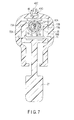
- FIG. 7 is a cross-sectional view taken along a line VII-VIII in FIG. 4 .
- the movable handle 27 is attached to the cylindrical case 25 through a fulcrum pin 71.
- the movable handle 27 pivots with respect to the cylindrical case 25 about the fulcrum pin 71 at the center.
- the movable handle 27 includes arm portions 72A and 72B.
- An engagement protrusion 73A protruding toward an inner peripheral direction is provided to the arm portion 72A, and an engagement protrusion 73B protruding toward the inner peripheral direction is provided to the arm portion 72B.
- a slide member 75 is arranged to the outer peripheral direction side of the movable cylindrical member 36.
- An engagement groove 76 which is concave toward the inner peripheral direction, is formed on the slide member 75 along the periaxial directions.
- the slide member 75 is provided in a second coupling region X2 in the cylindrical case 25, the second coupling region X2 being placed to the distal direction side of the first coupling region X1. Therefore, the movable handle 27 is attached to the slide member 75 in the second coupling region X2 in the cylindrical case 25.
- the slide member 75 is made of an insulating material. Therefore, the movable cylindrical member 36 (the sheath portion 31) is electrically insulated from the movable handle 27.
- a coil spring 77 and a stopper 78 are provided to the outer peripheral direction side of the movable cylindrical member 36.
- One end of the coil spring 77 is connected to a distal end of the slide member 75, and the other end of the same is connected to the movable cylindrical member 36.
- the stopper 78 is configured to regulate movement of the slide member 75 toward the proximal direction.
- the slide member 75 moves with respect to the movable cylindrical member 36 along the longitudinal axis C.
- a force which is not smaller than a predetermined force, is applied to the movable cylindrical member 36 from the slide member 75 through the coil spring 77, the movable cylindrical member 36 moves with respect to the handle unit 4 and the probe 5 along the longitudinal axis C integrally with the slide member 75.
- the movable cylindrical member 36 moves, the movable pipe 63 moves along the longitudinal axis C integrally with the movable cylindrical member 36.
- the jaw 32 opens or closes with respect to the distal end portion of the probe 5.
- the slide member 75, the movable cylindrical member 36, and the movable pipe 63 serve as a movable portion 70 which moves with respect to the handle unit 4 and the probe 5 along the longitudinal axis C in accordance with the opening/closing motions of the movable handle 27 with respect to the fixed handle 26.
- the movable portion 70 is coupled with the movable handle 27 in the second coupling region X2 in the cylindrical case 25, the second coupling portion X2 being placed to the distal direction side of the first coupling region X1.
- the jaw 32 opens or closes with respect to the distal end portion of the probe 5.
- a first suction tube member (a first tube member) 81 is extended along the longitudinal axis C.
- the first suction tube member (first aspiration tube member) 81 is extended to a bending position Y2 provided between the first coupling region X1 and the second coupling region X2. That is, the bending position Y2 is provided to the distal direction side of the first coupling region X1, and also provided to the proximal direction side of the second coupling region X2.
- the hole-shaped portion 21 is extended to a region positioned to the proximal direction side of the bending position Y2 of the first suction tube member 81.
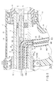
- FIG. 8 is a view showing a configuration between the first coupling region X1 and the second coupling region X2 in the cylindrical case 25.
- the opening hole 24 of the probe 5 is placed between the first coupling region X1 and the second coupling region X2.
- an opening hole 82 extended in the radial directions from an outer peripheral portion of the fixed cylindrical member 35 is provided between the first coupling region X1 and the second coupling region X2.
- the first suction tube member 81 is bent at the bending position Y2. Further, it is extended to the outer peripheral direction side of the fixed cylindrical member 35 through the opening hole 24 and the opening hole 82. That is, the first suction tube member 81 bent at the bending position Y2 is extended to the outside of the treatment unit (surgery unit) 3 through the outer peripheral portion of the probe 5.
- a first suction path (a first path) 50A that is opened at the opening position Y1 at the distal end portion of the probe 5 is defined by a region of the hole defining surface 22 to the distal direction side of the first suction tube member 81 and the first suction tube member 81. That is, the region of the hole defining surface 22 to the distal direction side of the first suction tube member 81 and the first suction tube member 81 form a first suction path defining portion (a first path defining portion) 60A that defines the first suction path (first aspiration path) 50A. Furthermore, the first suction path defining portion (first aspiration path defining portion) 60A is extended to the bending position Y2 in the probe 5 along the longitudinal axis C. Furthermore, the first suction path defining portion 60A is bent at the bending position Y2, and extended to the outside of the treatment unit 3 through the outer peripheral portion of the probe 5.
- the first suction tube member 81 is made of a material having high strength and high heat resistance properties, and its resistance properties with respect to ultrasonic vibration are enhanced. Furthermore, the first suction tube member 81 is made of a material having high elasticity and avoids generation of abnormal noise when coming into contact with the ultrasonically vibrating probe 5. Therefore, as the first suction tube member 81, for example, a polytetrafluoroethylene (PTFE) tube or a polyether ether ketone (PEEK) tube is used as the first suction tube member 81.
- PTFE polytetrafluoroethylene
- PEEK polyether ether ketone
- a first liquid supply tube member (a first tube member) 91 is extended between the probe 5 and the sheath portion 31 along the longitudinal axis C.
- the first liquid supply tube member 91 is extended to a bending position Z2 provided between the first coupling region X1 and the second coupling region X2. That is, the bending position Z2 is provided to the distal direction side of the first coupling region X1, and also provided to the proximal direction side of the second coupling region X2.
- the first liquid supply tube member 91 is bent at the bending position Z2. Further, it is extended to the outer peripheral direction side of the fixed cylindrical member 35 through the opening hole 82. That is, the first liquid supply tube member 81 bent at the bending position Z2 is extended to the outside of the treatment unit 3.
- a first liquid supply path (a first path) 50B is defined by the outer peripheral portion of the probe 5 and the inner peripheral portion of the sheath portion 31.
- the first liquid supply path 50B is opened at the opening position Z1 at the distal end of the sheath portion 31.
- the first liquid supply tube member 91 serves as a first liquid supply path defining portion (a first path defining portion) 60B that defines the first liquid supply path 50B. Furthermore, in the region to the distal direction side of the first liquid supply tube member 91, the outer peripheral portion of the probe 5 and the inner peripheral portion of the sheath portion 31 form the first liquid supply path defining portion 60B that defines the first liquid supply path 50B.
- the first liquid supply path defining portion 60B is extended to the bending position Z2 between the probe 5 and the sheath portion 31 along the longitudinal axis C. Moreover, the first liquid supply path defining portion 60B is bent at the bending position Z2, and extended from the outer peripheral portion of the probe 5 to the outside of the treatment unit 3.
- the first liquid supply tube member 91 like the first suction tube member 81, using, e.g., a PTFE tube or a PEEk tube is preferable. Additionally, it is preferable for the bending position Z2 of the first liquid supply tube member 91 (the first liquid supply path defining portion 60B) to be provided at a node position of the ultrasonic vibration.
- a second suction tube member (a second tube member) 83 is directly connected to the first suction tube member 81 extended to the outside of the treatment unit 3.
- the second suction tube member (second aspiration tube member) 83 is extended in the fixed handle 26 along the handle extending direction (the direction of the arrow A in FIG. 4 ).
- the second suction tube member 83 is extended to an extending position Y3 provided on the handle extending direction side part of the fixed handle 26.
- the second suction tube member 83 has a rigidity lower than that of the first suction tube member 81. Therefore, the second suction tube member 83 is flexible, and it can be readily oriented from the inside of the cylindrical case 25 toward the inside of the fixed handle 26. It is to be noted that, as the second suction tube member 83, a silicone tube or the like can be used.
- an external suction tube (an external tube) 85 is connected to the second suction tube 83.
- the external suction tube (external aspiration tube) 85 is extended from the extending position Y3 to the outside of the handle unit 4. Further, as shown in FIG. 1 , the external suction tube 85 is connected to a suction unit (aspiration unit) 87.
- the suction unit 87 is connected to the control section 10 in the power supply unit 7.
- the second suction tube member 83 and the external suction tube 85 define a second suction path (a second path) 80A communicating with the first suction path 50A outside the treatment unit 3. That is, the second suction tube member 83 and the external suction tube 85 serve as a second suction path defining portion (a second path defining portion) 90A that defines the second suction path (second aspiration path) 80A.
- the second suction path defining portion (second aspiration path defining portion) 90A is extended in the fixed handle 26 of the handle unit 4 from the outside of the treatment unit 3 along the handle extending direction. Furthermore, the second suction path defining portion 90A is extended to the outside of the handle unit 4 from the extending position Y3 provided on the handle extending direction side part of the fixed handle 26.
- a second liquid supply tube member (a second tube member) 93 is directly connected to the first liquid supply tube member 91 extended to the outside of the treatment unit 3.
- the second liquid supply tube member 93 is extended in the fixed handle 26 along the handle extending direction (the direction of the arrow A in FIG. 4 ).
- the second liquid supply tube member 93 is extended to an extending position Z3 provided on the handle extending direction side part of the fixed handle 26.
- the second liquid supply tube member 93 has a rigidity lower than that of the first liquid supply tube member 91. Therefore, the second liquid supply tube member 93 is flexible and can be easily oriented from the inside of the cylindrical case 25 toward the inside of the fixed handle 26. It is to be noted that, as the second liquid supply tube member 93, a silicone tube or the like is used.
- an external liquid supply tube (an external tube) 95 is connected to the second liquid supply tube member 93.
- the external liquid supply tube 95 is extended to the outside of the handle unit 4 from the extending position Z3. Furthermore, as shown in FIG. 1 , the external liquid supply tube 95 is connected to a liquid supply unit 97.
- the liquid supply unit 97 is connected to the control section 10 of the power supply unit 7.
- the second liquid supply tube member 93 and the external liquid supply tube 95 define a second liquid supply path (a second path) 80 communicating with the first liquid supply path 50B outside the treatment unit 3. That is, the second liquid supply tube member 93 and the external liquid supply tube 95 form a second liquid supply path defining portion (a second path defining portion) 90B that defines the second liquid supply path 80B.
- the second liquid supply path defining portion 90B is extended from the outside of the treatment unit 3 in the fixed handle 26 of the handle unit 4 along the handle extending direction. Further, the second liquid supply path defining portion 90B is extended to the outside of the handle unit 4 from the extending position Z3 provided on the handle extending direction side part of the fixed handle 26.
- the probe 5 includes a cavity forming portion 102 between the first coupling region X1 and the second coupling region X2.
- a cavity portion 101 is formed between the first coupling region X1 and the second coupling region X2.
- the cavity forming portion 102 is provided with a dimension larger than a half wavelength of the ultrasonic vibration between the first coupling region X1 and the second coupling region X2 along the longitudinal axis C.
- the first suction tube member 81 that is bent at the bending position Y2 is extended to the cavity portion 101 through the outer peripheral portion of the cavity forming portion 101. Further, in the cavity portion 101, the second suction tube member 83 is connected to the first suction tube member 81.
- the cavity forming portion 102 has the dimension larger than the half wavelength of the ultrasonic vibration between the first coupling region X1 and the second coupling region X2 along the longitudinal axis C. Therefore, the cavity portion 101 has a size that is sufficient to prevent the second suction tube member 83 from coming into contact with the electrical connection ring 39, the arm portions 72A and 72B of the movable handle 27, and other parts.
- the second suction member 83 Since contact with the electrical connection ring 39 and other parts in the cavity portion 101 is avoided, the second suction member 83 does not receive a force from the electrical connection ring 39 or the like. Therefore, crushing or twisting of the second suction tube member 83 in the cavity portion 101 is avoided. Therefore, the second suction tube member 83 can be easily oriented toward the inside of the fixed handle 26 from the cavity portion 101.
- the first liquid supply tube member 91 bent at the bending position Z2 is extended to the cavity portion 101 from the outer peripheral portion of the cavity forming portion 102 through the opening hole 82. Furthermore, in the cavity portion 101, the second liquid supply tube member 93 is connected to the first liquid supply tube member 91.
- the cavity forming portion 102 has the dimension larger than the half wavelength of the ultrasonic vibration between the first coupling region X1 and the second coupling region X2 along the longitudinal axis C. Therefore, the cavity portion 101 has a size that is sufficient to prevent the second liquid supply tube member 93 to come into contact with the electrical connection ring 39, the arm portions 72A and 72B of the movable handle 27, and other parts.
- the second liquid supply tube member 93 Since the contact with the electrical connection ring 39 and other parts in the cavity portion 101 is avoided, the second liquid supply tube member 93 does not receive a force from the electrical connection ring 39 or the like. Therefore, crushing or twisting of the second liquid supply tube member 93 in the cavity 101 is avoided. Therefore, the second liquid supply tube member 93 can be easily oriented toward the inside of the fixed handle 26 from the cavity portion 101.
- FIG. 9 is a cross-sectional view taken along a line IX-IX in FIG. 4 .
- a protruding portion 105 protruding toward the inner peripheral direction is formed at the distal end portion of the cylindrical case 25 of the handle unit 4.
- the protruding portion 105 is extended over all-round circumference of the cylindrical case 25 along the periaxial directions.
- a groove defining portion 107 that defines a groove-shaped portion 106 that is concave toward the inner peripheral direction is provided on the rotating operation knob 29.
- the groove defining portion 107 is extended over all-round circumference of the cylindrical case 25 along the periaxial direction.
- the protruding portion 105 of the cylindrical case 25 includes a fixed-side convex portion 111 that protrudes toward the inner peripheral direction beyond other parts of the protruding portion 105. Furthermore, the groove defining portion 107 of the rotating operation knob 29 includes a movable-side convex portion 112 that protrudes toward the outer peripheral direction from a bottom portion. Since the rotating operation knob 29 is attached to the cylindrical case 25 to be rotatable in the periaxial directions, the movable-side convex portion 112 is movable in the periaxial directions with respect to the fixed-side convex portion 111.
- the fixed-side convex portion 111 and the movable-side convex portion 112 form a rotation regulating portion 110 configured to regulate the rotation range of the rotating operation knob 29 with respect to the cylindrical case 25 in the periaxial directions to 360° or below.
- the rotation range of the treatment unit 3 (the probe 5, the sheath portion 31, and the jaw 32) with respect to the cylindrical case 25 in the periaxial directions is regulated to 360° or below.
- a function of the ultrasonic treatment device 1 according to this embodiment will now be described.
- an operator presses any one of the input buttons 42A to 42C, the first input section 23A, the second input section 23B, and the third input section 23C in accordance with a treatment (surgery).
- a treatment surgery
- an electrical signal is transmitted from any one of the switch sections 43A to 43C, the first input section 23A, the second input section 23B, and the third input section 23C to the control section 10 in the power supply unit 7.
- the ultrasonic vibrator 12 When the first input section 23A is pressed, an electric current is supplied from the ultrasonic supply section 8 to the ultrasonic vibrator (ultrasonic oscillator) 12 through the electrical signal lines 13A and 13B, and the ultrasonic vibrator 12 generates the ultrasonic vibration. Further, the ultrasonic vibration is transmitted to the distal end of the probe 5. Moreover, the liquid supply unit 97 is driven, and a liquid such as water (physiological saline) is supplied through the second liquid supply path 80B and the first liquid supply path 50B. At this time, the liquid is supplied to a body tissue (biological tissue) from the opening position Z1 of the first liquid supply path 50B provided at the distal end of the sheath portion 31.
- a liquid such as water (physiological saline)
- cavitation Based on the transmission of the ultrasonic vibration and the supply of the liquid to the distal end of the probe 5, cavitation occurs.
- the cavitation enables selectively shattering (crushing) a body tissue with low elasticity such as a liver tissue. At this time, a body tissue with high elasticity such as a blood vessel is not shattered by the cavitation.
- the suction unit 87 is driven. Therefore, the body tissue shattered by the cavitation is suctioned (aspirated) from the opening position Y1 in the distal end portion of the probe 5.
- the body tissue is suctioned and collected by the suction unit 87 through the first suction path 50A and the second suction path 80A. As described above, when the first input section 23A is pressed, the ultrasonic suction is carried out.
- the liquid supply unit 97 alone is driven. As a result, the liquid is supplied from the opening position Z1 through the second liquid supply path 80B and the first liquid supply path 50B. At this time, the ultrasonic vibration is not produced, and the suction unit 87 does not perform suction. Furthermore, when the third input section 23C is pressed, the suction unit 87 alone is driven. As a result, the suction is performed from the opening position Y1 through the first suction path 50A and the second suction path 80A. At this time, the ultrasonic vibration is not generated, and the liquid is not supplied by the liquid supply unit 97.
- the input button 42A when the input button 42A is pressed, the electric current is supplied from the ultrasonic supply section 8 to the ultrasonic vibrator 12 via the electrical signal lines 13A and 1B, and the ultrasonic vibration is generated. Additionally, the ultrasonic vibration is transmitted to the distal end of the probe 5. At this time, the suction unit 87 and the liquid supply unit 97 are not driven. Friction heat generated by the ultrasonic vibration of the probe 5 enables cutting-and-coagulation with respect to the body tissue such as a blood vessel gripped between the distal end portion of the probe 5 and the jaw 32. As described above, when the input button 42A is pressed, the ultrasonic cutting-and-coagulation is carried out.
- a high-frequency current may be output from the high-frequency current supply section 9.
- the high-frequency current flows through the probe-side current path and the jaw-side current path. Further, the body tissue gripped between the distal end portion of the probe 5 and the jaw 32 is reformed by the high-frequency current, and the coagulation is facilitated.
- the high-frequency current flows through the probe-side current path and the jaw-side current path. Furthermore, the distal end portion of the probe 5 and the jaw 32 are used as electrodes, and a bipolar treatment is performed. At this time, the ultrasonic vibration is not generated, and the suction unit 87 is not driven. Moreover, when the input button 42C is pressed, the high-frequency current does not flow through the jaw-side current path, but the high-frequency current flows through the probe-side current path alone. Additionally, the distal end portion of the probe 5 is used as the electrode, and a monopolar treatment is performed. At this time, the ultrasonic vibration is not generated, and the suction unit 87 is not driven.
- the liquid supply unit 97 may be driven.
- the bipolar treatment and the monopolar treatment are carried out while dropping the liquid, e.g., physiological saline onto the body tissue.
- both the ultrasonic suction treatment (ultrasonic suction surgery) and the ultrasonic cutting-and-coagulation treatment (ultrasonic cutting-and-coagulation surgery) can be performed without counterchanging or recombining the devices.
- the body tissue is suctioned and collected by the suction unit 87 through the first suction path 50A and the second suction path 80A.
- the first suction path defining portion 60A is extended from the opening position Y1 of the distal end portion of the probe 5 to the bending position Y2 in the probe 5 along the longitudinal axis C. Further, the first suction path defining portion 60A is bent at the bending position Y2, and extended to the outside of the treatment unit 3 through the outer peripheral portion of the probe 5.
- the bending position Y2 is provided to the distal end direction side of the first coupling region X1 of the vibrator unit 2 and the treatment unit 3.
- the first suction path 50A communicates with the second suction path 80A.
- the second suction path defining portion 90A that defines the second suction path 80A is extended from the outside of the treatment unit 3 in the fixed handle 26 of the handle unit 4 along the handle extending direction.
- the second suction path defining portion 90A is extended from the extending position Y3 provided on the handle extending direction side part of the fixed handle 26 to the outside of the handle unit 4.
- an ultrasonic treatment device 1A will now be considered.
- a suction path 115 is extended from an inside of a probe 3A via an inside of a horn 15A and an inside of an ultrasonic vibrator 12A along the longitudinal axis C.
- the suction path 115 is connected to a suction tube 116 at a proximal end portion of the ultrasonic vibrator 12A.
- the suction tube 116 is extended to the outside of a vibrator case 11A of a vibrator unit 2A.
- the ultrasonic vibrator (12, 12A) is not disposed, and it is reused. Therefore, in the ultrasonic treatment device (1, 1A), a treatment unit (3, 3A) and a handle unit (4, 4A) are disposed after use, and the vibrator unit (2, 2A) is reused.
- the suction path 115 is provided in the ultrasonic vibrator 12A, sterilization and cleaning are required after use. Further, the suction tube 116 connected to the vibrator unit 2A is disposed after use. Therefore, after use of the ultrasonic treatment device 1A, the vibrator unit 2A must be removed from the handle unit 4A, and the suction tube 116 must be removed from the vibrator unit 2A. In preparation of assembling the ultrasonic treatment device 1A, the vibrator unit 2A must be coupled with the handle unit 4A, and the suction tube 116 must be connected to the vibrator unit 2A.
- the first suction path defining portion 60A and the second suction path defining portion 90A are not provided in the vibration unit 2. Therefore, the vibrator unit 2 does not have to be sterilized and cleaned after use. Furthermore, in the ultrasonic treatment device 1, the first suction tube member 81, the second suction tube member 83, and the external suction tube 85 are disposed without being removed from the handle unit 4 and the treatment unit 3.
- the ultrasonic treatment device 1 just removing the vibrator unit 2 from the cylindrical case 25 (the handle unit 4) and the treatment unit 3 enables integrally disposing (discarding) the first suction tube member 81, the second suction tube member 83, and the external suction tube 85 with the handle unit 4 and the treatment unit 3.
- the assembly preparation can be easily carried out.
- the first suction tube member 81 is formed integrally with the treatment unit 3, and the second suction tube member 83 and the external suction tube 85 are formed integrally with the handle unit 4.
- the second suction tube member 83 is connected to the first suction tube member 81, and then the treatment unit 3 is coupled with the cylindrical case 25 from the distal direction side.
- the vibrator unit 2 is coupled with the cylindrical case 25 from the proximal direction side, and the treatment unit 3 is coupled with the vibrator unit 2 in the first coupling region X1.
- the ultrasonic treatment device 1 is assembled without connecting the second suction tube member 83 and the external suction tube 85 to the vibrator unit 2.
- the processing after use, the assembly preparation, and other tasks can be easily carried out.
- the center of gravity is located to the proximal direction side of a position where the operator grips, and the balance of the center of gravity at the time of a treatment becomes poor.
- the first suction path defining portion 60A is bent at the bending position Y2 provided to the distal direction side of the first coupling region X1, and is extended to the outside of the treatment unit 3 through the outer peripheral portion of the probe 5.
- the second suction path defining portion 90A connected to the first suction path defining portion 60A outside the treatment unit 3 is extended in the fixed handle 26 of the handle unit 4 along the handle extending direction.
- the second suction path defining portion 90A is extended to the outside of the handle unit 4 from the extending position Y3 provided on the handle extending direction side part of the fixed handle 26.
- the first liquid supply path defining portion 60B is bent at the bending position Z2 provided to the distal direction side of the first coupling region X1, and extended to the outside of the treatment unit 3 from the outer peripheral portion of the probe 5. Furthermore, the second liquid supply path defining portion 90B connected to the first liquid supply path defining portion 60B outside the treatment unit 3 is extended in the fixed handle 26 of the handle unit 4 along the handle extending direction. Moreover, the second liquid supply path defining portion 90B is extended to the outside of the handle unit 4 from the extending position Z3 provided on the handle extending direction side part of the fixed handle 26.
- the second suction path defining portion 90A and the second liquid supply path defining portion 90B, passing through the inside of the fixed handle 26, are extended to the outside of the handle unit 4 from the extending position (Y3, Z3) located on the handle extending direction side part of the fixed handle 26. Therefore, the weight of the part to the proximal direction side of the handle unit 4 is not increased, and the center of gravity of the ultrasonic treatment device 1 is placed on the handle unit 4. Therefore, in the case of performing a treatment while gripping the fixed handle 26 and the movable handle 27, a position where an operator grips coincides with the position of the center of gravity in directions parallel to the longitudinal axis C. As a result, the treatment is performed with an excellent balance of the center of gravity, and the distal end portion of the probe 5 and the jaw 32 can be readily positioned at the time of a treatment. Therefore, the operability during the treatment can be improved.
- the rotating operation knob 29 when the rotating operation knob 29 is rotated with respect to the cylindrical case 25, the probe 5 and the jaw 32 rotate in one of the periaxial directions with respect to the cylindrical case 25.
- the fixed-side convex portion 111 and the movable-side convex portion 112 regulate the rotation range of the rotating operation knob 29 (the treatment unit 3) in the periaxial directions with respect to the cylindrical case 25 to 360° or below.
- the cavity forming portion 102 of the probe 5 is provided with a dimension larger than the half wavelength of the ultrasonic vibration between the first coupling region X1 and the second coupling region X2 along the longitudinal axis C. Therefore, in the cylindrical case 25, the cavity portion 101 is formed between the first coupling region X1 and the second coupling region X2.
- the first suction tube member 81 bent at the bending position Y2 is extended to the cavity portion 101 through the outer peripheral portion of the cavity forming portion 102. Additionally, in the cavity portion 101, the second suction tube member 83 is connected to the first suction tube member 81.
- first liquid supply tube member 91 bent at the bending position Z2 is extended to the cavity portion 101 from the outer periphery of the cavity forming portion 102 through the opening hole 82. Furthermore, in the cavity portion 101, the second liquid supply tube member 93 is connected to the first liquid supply tube member 91.
- an ultrasonic treatment device 1B will now be considered.
- a dimension of a cavity forming portion 102B in a probe 5B between a first coupling region X1 and a second coupling region X2 along the longitudinal axis C is smaller than the half wavelength of the ultrasonic vibration. Therefore, a cavity portion 101B in the cylindrical case 52B is narrower than the cavity portion 101 in the first embodiment.
- a bending position Y2 of a first suction tube member 81B is provided between the first coupling region X1 and the second coupling region X2.
- the second suction tube member 83B is connected to the first suction tube member 81B.
- a bending position Z2 of a first liquid supply tube member 91B is provided between the first coupling region X1 and the second coupling region X2.
- a second liquid supply tube member 93B is connected to a first liquid supply tube member 91B.
- the cavity portion 101B is narrow, the second suction tube member 83B and the second liquid supply tube member 93B are apt to come into contact with an electrical connection ring 39B, arm portions 72A and 72B of a movable handle 27B, and other parts in a cylindrical case 25B. That is, the cavity portion 101B is not of a size sufficient to prevent the second suction tube member 83B and the second liquid supply tube member 93B from coming into contact with the electrical connection ring 39, arm portions 72A and 72B of a movable handle 27B, and other parts.
- the second suction tube member 83B and the second liquid supply tube member 93B When the second suction tube member 83B and the second liquid supply tube member 93B come into contact with the electrical connection ring 39B and other parts, they receive a force from the electrical connection ring 39B and other parts. Upon receiving the force from the electrical connection ring 39B and other parts, the second suction tube member 83B and the second liquid supply tube member 93B are crushed and twisted in the cavity portion 101B. Therefore, it is difficult to orient the second suction tube member 83B and the second liquid supply tube member 93B from the cavity portion 101B toward the inside of the fixed handle 26B.
- the second suction tube member 83B and the second liquid supply tube member 93B are crushed and twisted and the treatment unit 3B thereby rotates in the periaxial directions, the second suction tube member 83B and the second liquid supply tube member 93B are apt to wind around the outer peripheral portion of the sheath portion 31B.
- the cavity forming portion 102 of the probe 5 is provided with a dimension larger than the half wavelength of the ultrasonic vibration between the first coupling region X1 and the second coupling region X2 along the longitudinal axis C. Furthermore, the cavity forming portion 102 forms the cavity portion 101. Therefore, the cavity portion 101 has a size that is sufficient to prevent the second suction tube member 83 and the second liquid supply tube member 93 from coming into contact with the electrical connection ring 39, the arm portions 72A and 72B of the movable handle 27, and other parts.
- the second suction tube member 83 and the second liquid supply tube member 93 do not receive a force from the electrical connection ring 39 and other parts. Therefore, crushing and twisting of the second suction tube member 83 and the second liquid supply tube member 93 in the cavity portion 101 are avoided. Accordingly, the second suction tube member 83 and the second liquid supply tube member 93 can be readily oriented toward the inside of the fixed handle 26 from the cavity portion 101.
- the second suction tube member 83 and the second liquid supply tube member 93 are not crushed and twisted, when the treatment unit 3 rotates in the periaxial directions, the second suction tube member 83 and the second liquid supply tube member 93 are apt to wind around the outer peripheral portion of the sheath portion 31.
- the second suction tube member 83 and the second liquid supply tube member 93 are not in contact with the electrical connection ring 39 and other parts, when the rotation range of the treatment unit 3 is set to 360° or below, the second suction tube member 83 and the second liquid supply tube member 93 can be prevented from winding around the outer peripheral portion of the sheath portion 31.
- the fixed-side convex portion 111 and the movable-side convex portion 112 are configured to regulate the rotation range of the rotating operation knob 29 in the periaxial directions with respect to the cylindrical case 25 to 360° or below. Therefore, the rotation range of the treatment unit 3 is also regulated to 360° or below. Therefore, when the treatment unit 3 rotates in the periaxial directions, the second suction tube member 83 and the second liquid supply tube member 93 can be effectively prevented from winding around the outer peripheral portion of the sheath portion 31.
- the cavity forming portion 102 having a dimension larger than the half wavelength of the ultrasonic vibration is provided between the first coupling region X1 and the second coupling region X2 along the longitudinal axis C.
- the fixed-side convex portion 111 is provided to the cylindrical case 25, and the movable-side convex portion 112 is provided to the rotating operation knob 29.
- the second suction tube member 83 and the second liquid supply tube member 93 can be prevented from winding around the outer peripheral portion of the sheath portion 31. That is, the second suction tube member 83 and the second liquid supply tube member 93 are prevented from winding around the outer peripheral portion of the sheath portion 31 without providing different members other than members required in a treatment using the ultrasonic treatment device 1.
- the second suction tube member 83 has a rigidity lower than that of the first suction tube member 81, and the second liquid supply tube member 93 has a rigidity lower than that of the first liquid supply tube member 91. Therefore, in the cavity portion 101, the second suction tube member 83 and the second liquid supply tube member 93 can easily bend. Therefore, the second suction tube member 83 and the second liquid supply tube member 93 can be easily oriented from the inside of the cylindrical case 25 toward the inside of the fixed handle 26.
- the bending position Y2 of the first suction tube member 81 (the first suction path defining portion 60A) is provided at a node position of the ultrasonic vibration.
- the bending position Z2 of the first liquid supply tube member 91 (the first liquid supply path defining portion 60B) is provided at the node position of the ultrasonic vibration.
- a displacement due to the ultrasonic vibration is zero. Therefore, the first suction tube member 81 is hardly affected by the ultrasonic vibration at the bending position Y2, and the first suction tube member 81 is effectively prevented from being damaged.
- the first liquid supply tube member 91 is hardly affected by the ultrasonic vibration at the bending position Z2, and the first liquid supply tube member 91 is effectively prevented from being damaged.
- the ultrasonic treatment device 1 having the above-described configuration provides the following effects. That is, the ultrasonic treatment device 1 can provide both the ultrasonic suction treatment and the ultrasonic cutting-and-coagulation treatment without, e.g., counterchanging or recombining the devices.
- the first suction path defining portion 60A and the second suction path defining portion 90A are not provided in the vibrator unit 2. Therefore, the vibrator unit 2 does not have to be sterilized or cleaned after use. Further, in the ultrasonic treatment device 1, the first suction tube member 81, the second suction tube member 83, and the external suction tube 85 are disposed without being removed from the handle unit 4 and the treatment unit 3. That is, in the ultrasonic treatment device 1, just removing the vibrator unit 2 from the cylindrical case 25 (the handle unit 4) and the treatment unit 3 enables integrally disposing the first suction tube member 81, the second suction tube member 83, and the external suction tube 85 with the handle unit 4 and the treatment unit 3.
- the ultrasonic treatment device 1 can be assembled without connecting the second suction tube member 83 and the external suction tube 85 to the vibrator unit 2. As described above, in accordance with the ultrasonic treatment device 1 according to this embodiment, the processing after use, the assembly preparation, and other tasks can be readily carried out.
- the second suction path defining portion 90A and the second liquid supply path defining portion 90B pass through the inside of the fixed handle 26, and are extended to the outside of the handle unit 4 from the extending position (Y3, Z3) of the fixed handle 26 located on the handle extending direction side part. Therefore, the weight on a part to the proximal direction side of the handle unit 4 is not increased, and the center of gravity of the ultrasonic treatment device 1 is within the handle unit 4. Therefore, at a time of performing a treatment while gripping the fixed handle 26 and the movable handle 27, a position where an operator (surgeon) grips coincides with the position of the center of gravity in the directions parallel to the longitudinal axis C. As a result, the treatment can be performed with excellent balance of the center of gravity, and the distal end portion of the probe 5 and the jaw 32 can be readily positioned at the time of the treatment. Therefore, the operability during the treatment can be improved.
- the probe 5 includes a cavity forming portion 102 having a dimension larger than the half wavelength of the ultrasonic vibration between the first coupling region X1 and the second coupling region X2 along the longitudinal axis C. Further, the cavity forming portion 102 forms the cavity portion 101. Therefore, the cavity portion 101 has a size that is sufficient to prevent the second suction tube member 83 and the second liquid supply tube member 93 from coming into contact with the electrical connection ring 39, the arm portions 72A and 72B of the movable handle 27, and other parts.
- the second suction tube member 83 and the second liquid supply tube member 93 do not receive force from the electrical connection ring 39 and other parts. Therefore, crushing or twisting of the second suction tube member 83 and the second liquid supply tube member 93 in the cavity portion 101 can be prevented. Accordingly, the second suction tube member 83 and the second liquid supply tube member 93 can be easily orientated from the cavity portion 101 toward the inside of the fixed handle 26.
- the second suction tube member 83 and the second liquid supply tube member 93 are not crushed or twisted, when the treatment unit 3 rotates in the periaxial directions, it is difficult for the second suction tube member 83 and the second liquid supply tube member 93 to wind around the outer peripheral portion of the sheath portion 31.
- setting the rotation range of the treatment unit 3 to 360° or below enables preventing the second suction tube member 83 and the second liquid supply tube member 93 from winding around the outer peripheral portion of the sheath portion 31.
- the fixed-side convex portion 111 and the movable-side convex portion 112 are configured to regulate the rotation range of the rotating operation knob 29 in the periaxial directions with respect to the cylindrical case 25 to 360° or below. Therefore, the rotation range of the treatment unit 3 is also regulated to 360° or below. Therefore, when the treatment unit 3 rotates in the periaxial directions, the second suction tube member 83 and the second liquid supply tube member 93 can be effectively prevented from winding around the outer peripheral portion of the sheath portion 31.
- the ultrasonic treatment device 1 it is possible to prevent the second suction tube member 83 and the second liquid supply tube member 93 from winding around the outer peripheral portion of the sheath portion 31 without providing different members other than members required in a treatment using the ultrasonic treatment device 1.
- the second suction tube member 83 has a rigidity lower than that of the first suction tube member 81, and the second liquid supply tube member 93 has a rigidity lower than that of the first liquid supply tube member 91. Therefore, in the cavity portion 101, the second suction tube member 83 and the second liquid supply tube member 93 can easily bend. Therefore, the second suction tube member 83 and the second liquid supply tube member 93 can be further easily oriented from the inside of the cylindrical case 25 toward the inside of the fixed handle 26.
- the bending position Y2 of the first suction tube member 81 (the first suction path defining portion 60A) is provided at a node position of the ultrasonic vibration.
- the bending position Z2 of the first liquid supply tube member 91 (the first liquid supply path defining portion 60B) is provided at a node position of the ultrasonic vibration.
- a displacement caused due to the ultrasonic vibration is zero. Therefore, the first suction tube member 81 is hardly affected by the ultrasonic vibration at the bending position Y2, and the first suction tube member 81 can be effectively prevented from being damaged.
- the first liquid supply tube member 91 is hardly affected by the ultrasonic vibration at the bending position Z2, and the first liquid supply tube member 91 can be effectively prevented from being damaged.
- the movable handle 27 is placed to the distal direction side of the fixed handle 26, the present invention is not restricted thereto.
- the movable handle 27 may be placed to the proximal direction side of the fixed handle 26.
- the movable handle 27 is openable or closable with respect to the fixed handle 26 substantially in parallel with respect to the longitudinal axis C.
- the movable portion 70 (see FIG. 4 and FIG. 6 ) of the sheath portion 31 moves with respect to the handle unit 4 and the probe 5 along the longitudinal axis C.
- the jaw 32 is opened or closed with respect to the distal end portion of the probe 5.
- the present invention is not restricted thereto.
- the first suction tube member 81 may be extended to the opening position Y1 at the distal end of the first suction path defining portion 60A. In this case, the distal end of the first suction tube member 81 coincides with the opening position Y1 of the first suction path defining portion 60A.
- the first suction tube member 81 may be extended to the bending position Y2 along the longitudinal axis C in the hole-shaped portion 21 of the probe 5. Further, the first suction tube member 81 can be extended from the bending position Y2 to the outside of the treatment unit 3 through the outer peripheral portion of the probe 5.
- the first liquid supply tube member 91 it can be described the same matter as the first suction tube member 81. That is, the first liquid supply tube member 91 may be extended to the opening position Z1 at the distal end of the first liquid supply path defining portion 60B.
- a second embodiment according to the present invention will now be described with reference to FIG. 15 to FIG. 17 .
- the second embodiment can be obtained by modifying the configuration of the first embodiment as follows. It is to be noted that like reference numerals denote parts equal to those in the first embodiment, and a description thereof will be omitted.
- FIG. 15 is a view showing a configuration between a first coupling region X1 and a second coupling region X2 in a cylindrical case 25 according to this embodiment.
- a dimension of a probe 5 according to this embodiment between the first coupling region X1 and the second coupling region X2 along a longitudinal axis C is smaller than a half wavelength of an ultrasonic wave.
- a fixed-side member 121 and a movable-side member 122 are provided in the cylindrical case 25, a cavity portion 101 is not formed.
- the movable-side member 122 is coupled with the fixed-side member 121 to be rotatable in periaxial directions.
- the fixed-side member 121 is provided in a fixed state with respect to the cylindrical case 25.
- the movable-side member 122 is provided in a fixed state with respect to an outer peripheral portion of a fixed cylindrical member 35 of a sheath portion 31. Therefore, the movable-side member 122 rotatable with respect to the fixed-side member 121 and the cylindrical case 25 in the periaxial directions integrally with the sheath portion 31 (a treatment unit 3).
- the fixed-side member 121 and the movable-side member 122 are placed between the first coupling region X1 and the second coupling region X2.
- a first suction tube member 81 is bent at a bending position Y2 between the first coupling region X1 and the second coupling region X2, and extended to an outside of the treatment unit 3.
- a first liquid supply tube member 91 is bent at a bending position Z2 between the first coupling region X1 and the second coupling region X2, and extended to the outside of the treatment unit 3.
- the first suction tube member 81 and the first liquid supply tube member 91 are connected to the movable-side member 122 outside the treatment unit 3.
- a second suction tube member 83 and a second liquid supply tube member 93 are connected to the fixed-side member 121 outside the treatment unit 3. That is, the fixed-side member 121 and the movable-side member 122 connect the first suction tube member 81 to the second suction tube member 83. Furthermore, the fixed-side member 121 and the movable-side member 122 connect the first liquid supply member 91 to the second liquid supply tube member 93.
- FIG. 16 is a view showing a state in which the fixed-side member 121 is coupled with the movable-side member 122.
- FIG. 17 is a cross-sectional view taken along a line 17-17 in FIG. 16 .
- a first suction intermediate cavity (first aspiration intermediate cavity) 123A is provided between the fixed-side member 121 and the movable-side member 122.
- the first suction intermediate cavity 123A is provided to form a circle in periaxial directions.
- a first liquid supply intermediate cavity 123B is provided between the fixed-side member 121 and the movable-side member 122.
- the first liquid supply intermediate cavity 123B is placed to the outer peripheral direction side of the first suction intermediate cavity 123A, and it is provided to form a circle in the periaxial directions.
- each of the first suction intermediate cavity 123A and the first liquid supply intermediate cavity 123B is provided to form the circle in the periaxial directions between the fixed-side member 121 and the movable-side member 122 irrespective of a state of rotation of the movable-side member 122 with respect to the fixed-side member 121.
- a second suction intermediate cavity (second aspiration intermediate cavity) 125A and a second liquid supply intermediate cavity 125B are provided to the movable-side member 122 along the longitudinal axis C.
- a first suction path 50A communicates with the second suction intermediate cavity 125A.
- the second suction intermediate cavity 125A communicates with the first suction intermediate cavity 123A irrespective of the state of rotation of the movable-side member 122 with respect to the fixed-side member 121.
- a first liquid supply path 50B communicates with the second liquid supply intermediate cavity 125B.
- the second liquid intermediate cavity 125B communicates with the first liquid supply intermediate cavity 123B irrespective of the state of rotation of the movable-side member 122 with respect to the fixed-side member 121.
- a third suction intermediate cavity (third aspiration intermediate cavity) 127A and a third liquid supply intermediate cavity 127B each having an L-like shape are provided in the fixed-side member 121.
- a second suction path 80A communicates with the third suction intermediate cavity 127A.
- the third suction intermediate cavity 127A communicates with the first suction intermediate cavity 123A irrespective of the state of rotation of the movable-side member 122 with respect to the fixed-side member 121.
- a second liquid supply path 80B communicates with the third liquid supply intermediate cavity 127B.
- the third liquid supply intermediate cavity 127B communicates with the first liquid supply intermediate cavity 123B irrespective of the state of rotation of the movable-side member 122 with respect to the fixed-side member 121.
- the first suction intermediate cavity 123A, the second suction intermediate cavity 125A, and the third suction intermediate cavity 127A form a suction intermediate path (an intermediate path) 130A that intermediates between the first suction path 50A and the second suction path 80A.
- the fixed-side member 121 and the movable-side member 122 cooperatively define the suction intermediate path 130A so that the first suction path 50A communicates with the second suction path 80A irrespective of the state of rotation of the movable-side member 122 with respect to the fixed-side member 121.
- first liquid supply intermediate cavity 123B, the second liquid supply intermediate cavity 125B, and the third liquid supply intermediate cavity 127B form a liquid supply intermediate path (an intermediate path) 130B that intermediates between the first liquid supply path 80B and the second liquid supply path 80B.
- the fixed-side member 121 and the movable-side member 122 cooperatively define the liquid supply intermediate path 130B so that the first liquid supply path 50B communicates with the second liquid supply path 80B irrespective of the state of rotation of the movable-side member 122 with respect to the fixed-side member 121.
- the fixed-side member 121 and the movable-side member 122 form an intermediate path defining portion 120 that defines the suction intermediate path 130A and the liquid supply intermediate path 130B.
- the second suction tube member 83 and the second liquid supply tube member 93 are connected to the fixed-side member 121.
- the fixed-side member 121 is provided in the fixed state with respect to the cylindrical case 25 of the handle unit 4. Therefore, when the treatment unit 3 and the movable-side member 122 rotate in the periaxial directions integrally with a rotating operation knob 29, the fixed-side member 121, the second suction tube member 83, and the second liquid supply tube member 93 do not rotate. Therefore, when the treatment unit 3 rotates in the periaxial directions, the second suction tube member 83 and the second liquid supply tube member 93 are effectively prevented from winding around the outer peripheral portion of the sheath portion 31.
- the rotation range of the treatment unit 3 does not have to be restricted to 360° or below. Therefore, a rotation regulating portion 110 configured to regulate the rotation range of the rotating operation knob 29 with respect to the cylindrical case 25 in the periaxial directions to 360° or below does not have to be provided between the cylindrical case 25 and the rotating operation knob 29. Therefore, a fixed-side convex portion 111 and a movable-side convex portion 112 do not have to be provided between the cylindrical case 25 and the rotating operation knob 29, and a configuration between the cylindrical case 25 and the rotating operation knob 29 is simplified.
- the second suction tube member 83 and the second liquid supply member 93 are connected to the fixed-side member 121.
- the fixed-side member 121 is provided in the fixed state with respect to the cylindrical case 25 of the handle unit 4. Therefore, when the treatment unit 3 and the movable-side member 122 rotate in the periaxial directions integrally with the rotating operation knob 29, the fixed-side member 121, the second suction tube member 83, and the second liquid supply tube member 93 do not rotate. Therefore, when the treatment unit 3 rotates in the periaxial directions, the second suction tube member 83 and the second liquid supply tube member 93 can be effectively prevented from winding around the outer peripheral portion of the sheath portion 31.
- the rotation range of the treatment unit 3 does not have to be restricted to 360° or below. Therefore, the rotation regulating portion 110 configured to regulate the rotation range of the rotating operation knob 29 in the periaxial directions with respect to the cylindrical case 25 does not have to be provided between the cylindrical case 25 and the rotating operation knob 29. Therefore, the configuration between the cylindrical case 25 and the rotating operation knob 29 can be simplified.
- the suction intermediate path 130A and the liquid supply intermediate path 130B are not restricted to the configuration according to the second embodiment. That is, the fixed-side member 121 and the movable-side member 122 may cooperatively define the suction intermediate path 130A so that the first suction path 50A and the second suction path 80A communicate with each other irrespective of the state of rotation of the movable-side member 122 with respect to the fixed-side member 121. Further, the fixed-side member 121 and the movable-side member 122 may cooperatively define the liquid supply intermediate path 130B so that the first liquid supply path 50B and the second liquid supply path 80B communicate with each other irrespective of the state of rotation of the movable-side member 122 with respect to the fixed-side member 121.
- An ultrasonic treatment device comprising:
- the first path defining portion includes a first tube member which is extended to the bending position between the probe and the sheath portion along the longitudinal axis, and which is extended to the outside of the treatment unit from the bending position, and
- the second path defining portion includes a second tube member which is connected to the first tube member directly or through another member, and which is extended in the fixed handle along the handle extending direction.
- the handle unit includes a rotating operation section which is coupled to the distal direction side of the cylindrical case to be rotatable in periaxial directions with respect to the cylindrical case, and which is configured to rotate the treatment unit with respect to the cylindrical case in the periaxial directions by rotating with respect to the cylindrical case.
- the treatment unit includes a jaw which is pivotably attached to a distal end portion of the sheath portion, and which is openable/closable with respect to a distal end portion of the probe, and
- the sheath portion includes a movable portion which is coupled with the movable handle in a second coupling region in the cylindrical case located to the distal direction side of the first coupling region, and which is configured to open or close the jaw with respect to the distal end portion of the probe by moving with respect to the handle unit and the probe along the longitudinal axis in accordance with opening/closing motions of the movable handle with respect to the fixed handle.
- the handle unit includes a rotation regulating portion which is provided between the cylindrical case and the rotating operation section, and which is configured to regulate a rotation range of the rotating operation section in the periaxial directions with respect to the cylindrical case to 360° or below,
- the probe includes a cavity forming portion which is provided between the first coupling region and the second coupling region along the longitudinal axis with having a dimension larger than a half wavelength of the ultrasonic vibration, and which forms a cavity portion that allows connecting the first tube member to the second tube member between the first coupling region and the second coupling region in the cylindrical case, and
- the first tube member bent at the bending position is extended to the cavity portion from an outer peripheral portion of the cavity forming portion.
- the second tube member has a rigidity lower than that of the first tube member.
- the ultrasonic treatment device according to Additional Note 3, further comprising an intermediate path defining portion which defines an intermediate path that intermediates between the first path and the second path, and which connects the first tube member to the second tube member,
- the intermediate path defining portion includes a fixed-side member to which the second tube member is connected and which is provided to be fixed to the cylindrical case, and a movable-side member to which the first tube member is connected and which is rotatable with respect to the fixed-side member and the cylindrical case in the periaxial directions integrally with the treatment unit, and the movable-side member cooperating with the fixed-side member to define the intermediate path so that the first path communicates with the second path irrespective of a state of rotation of the movable-side member with respect to the fixed-side member.
- the second path defining portion includes an external tube which is connected to the second tube at the extending position, and which is extended to the outside of the handle unit.
Landscapes
- Health & Medical Sciences (AREA)
- Life Sciences & Earth Sciences (AREA)
- Engineering & Computer Science (AREA)
- General Health & Medical Sciences (AREA)
- Public Health (AREA)
- Veterinary Medicine (AREA)
- Nuclear Medicine, Radiotherapy & Molecular Imaging (AREA)
- Biomedical Technology (AREA)
- Animal Behavior & Ethology (AREA)
- Surgery (AREA)
- Radiology & Medical Imaging (AREA)
- Medical Informatics (AREA)
- Molecular Biology (AREA)
- Heart & Thoracic Surgery (AREA)
- Dentistry (AREA)
- Mechanical Engineering (AREA)
- Surgical Instruments (AREA)
- Ultra Sonic Daignosis Equipment (AREA)
Abstract
Description
- The present invention relates to an ultrasonic treatment device (ultrasonic surgical apparatus) configured to perform an ultrasonic treatment (ultrasonic surgery) including ultrasonic suction and ultrasonic cutting-and-coagulation.
-
Patent Literature 1 discloses an ultrasonic suction device which includes an ultrasonic vibrator (ultrasonic oscillator), and a horn configured to transmit ultrasonic vibration generated by the ultrasonic vibrator from a proximal end to a distal end. In this ultrasonic suction device (ultrasonic aspiration device), an suction path is extended inside the horn along a longitudinal axis. The suction path (aspiration path) is bent at a bending position to a proximal direction side of the horn, and extended from the bending position toward an outer peripheral direction. Further, a suction pipe (aspiration pipe) is connected to the suction path on an outer peripheral portion of the ultrasonic vibrator. In this ultrasonic suction device, ultrasonic suction is conducted by a distal surface of the ultrasonically vibrating horn with using a physical phenomenon called "cavitation". In more detail, since the horn repeats fast vibration that is performed several tens of thousands of times per second based on the ultrasonic vibration, a pressure periodically varies near the distal surface of the horn. When the pressure near the distal surface is lower than a saturated vapor pressure for a short time due to a variation in pressure, small air bubbles (cavities) are produced in a liquid in a body cavity or a liquid supplied to a position near a treatment position (surgical target) of a body tissue from the ultrasonic treatment device. Furthermore, a force, which acts when the pressure near the distal surface is increased (compressed), annihilates the produced air bubbles. The above-described physical phenomenon is called a "cavitation phenomenon". A body tissue having no elasticity, like a liver cell, is shattered (crushed) and emulsified by impact energy at the time of annihilation of the air bubbles. The shattered and emulsified body tissue is suctioned (aspirated) and collected from a suction opening (aspiration opening) at the distal end of the horn through the suction path and an inside of the suction pipe. At this time, a body tissue having high elasticity, like a blood vessel, is difficult to shatter since it absorbs impact shock, and thereby body tissues are selectively shattered. -
Patent Literature 2 discloses an ultrasonic cutting-and-coagulation device including an ultrasonic vibrator (ultrasonic oscillator), and a non-hollow (columnar) probe configured to transmit ultrasonic vibration generated by the ultrasonic vibrator from a proximal end to a distal end. This ultrasonic cutting-and-coagulation device includes an elongated sheath into which the probe is inserted, and a jaw openable/closable with respect to a distal end portion of the probe. Moreover, the ultrasonic cutting-and-coagulation device includes a handle unit. In the handle unit, a treatment unit (surgery unit) including the probe, the sheath, and the jaw is coupled with a vibrator unit (oscillator unit) including the ultrasonic vibrator. The handle unit includes a fixed handle, and a movable handle openable/closable with respect to the fixed handle. When the movable handle is opened/closed with respect to the fixed handle, a movable portion, provided to the sheath, moves along the longitudinal axis. As a result, the jaw is opened/closed with respect to the distal end portion of the probe. An ultrasonic cutting-and-coagulation treatment (ultrasonic cutting-and-coagulation surgery) is carried out by utilizing the ultrasonic vibration while gripping a body tissue such as a blood vessel between the distal end portion of the probe and the jaw. Specifically, when the probe ultrasonically vibrates in a state that a body tissue such as a blood vessel is gripped between the distal end portion of the probe and the jaw, frictional heat is generated between the distal end portion of the probe and the body tissue. Cutting and coagulation of the body tissue are simultaneously performed between the distal end portion of the probe and the jaw by using the generated frictional heat. Further, in this ultrasonic cutting-and-coagulation device, the distal end portion of the probe and the jaw are used as electrodes, and a bipolar treatment (bipolar surgery) using a high-frequency current is also carried out. -
- Patent Literature 1: Jpn. Pat. Appln. KOKAI Publication No.
Hei 7-16236 - Patent Literature 2: Jpn. Pat. Appln. KOKAI Publication No.
2008-264565 - For example, in case of resecting (excising) a liver, there is carried out an ultrasonic suction treatment in which a body tissue with no elasticity, such as a liver cell, is selectively shattered and emulsified by the cavitation and thereby the shattered body tissue is suctioned and collected. Additionally, a body tissue with high elasticity such as a blood vessel, that is selectively left, is subjected to the ultrasonic cutting-and-coagulation treatment. Here, generally, since the ultrasonic suction treatment and the ultrasonic cutting-and-coagulation treatment use different devices, the devices must be counterchanged in accordance with each treatment. Further, there is a treatment device (surgical apparatus) that can give both the ultrasonic suction treatment and the ultrasonic cutting-and-coagulation treatment. However, to exercise treatment functions required for the respective treatments, the devices are recombined. That is, a device counterchanging operation, a device recombining operation, and other operations are required in accordance with the respective treatments. Therefore, various problems occur, e.g., a reduction in continuity of an operation such as a surgical operation, a reduction in surgical efficiency, an increase in stress or fatigue of an operator (surgeon) due to prolongation of a procedure period (surgery time), an increased burden on a patient, and other problems. Therefore, a multifunctional medical treatment device (multifunctional surgical apparatus) that can give various medical treatments (surgical treatment) without counterchanging or recombining devices is demanded.
- Here, as an example of an ultrasonic treatment device requiring no recombination and so on of the ultrasonic suction device and the ultrasonic cutting-and-coagulation device, the following ultrasonic treatment device can be considered. That is, in the ultrasonic cutting-and-coagulation device disclosed in
Patent Literature 2, consideration will now be given to a situation where a hollow (cylindrical) probe in which a suction path (aspiration path) is provided from a distal end along a longitudinal axis is used in place of the non-hollow (columnar) probe. In this case, the suction path is extended along the longitudinal axis from an inside of the probe through an inside of a horn and an inside of an ultrasonic vibrator. The suction path is connected to a suction tube (aspiration tube) at a proximal end portion of the ultrasonic vibrator. Furthermore, the suction tube is extended to an outside of a vibrator case (oscillator case) of a vibrator unit. With such a configuration, a body tissue shattered and emulsified by the cavitation is suctioned and collected from a suction opening (aspiration opening) at a distal end of the probe through the suction path and an inside of the suction tube. Moreover, like the ultrasonic cutting-and-coagulation device disclosed inPatent Literature 2, an ultrasonic cutting-and-coagulation treatment is performed between the distal end portion of the probe and a jaw. Therefore, both the ultrasonic suction treatment and the ultrasonic cutting-and-coagulation treatment can be given without, e.g., counterchanging or recombining the devices. - However, in general, the vibrator unit is connected to one end of a cable in which an electrical signal line or the like, through which a current is supplied to the ultrasonic vibrator, is extended. Therefore, when the suction tube is connected to the vibrator unit in addition to the cable, a weight on a part to the proximal direction side of a handle unit is larger. An operator (surgeon) performs a treatment (surgery) while holding a fixed handle and a movable handle in the handle unit. Therefore, when the weight on the part to the proximal direction side of the handle unit is larger, the center of gravity is placed on a part to the proximal direction side of a position where the operator holds these handles, and thereby balance of the center of gravity at a time of each treatment becomes poor. Therefore, setting positions of the distal end portion of the probe and the jaw is difficult during each treatment, and operability at the time of the treatment is deteriorated.
- Moreover, in terms of materials and costs, generally, the ultrasonic vibrator is not disposed (discarded), but is reused. Therefore, in the ultrasonic treatment device including the treatment unit (surgery unit), the handle unit, and the vibrator unit, the treatment unit and the handle unit are disposed after use, and the vibrator unit is reused. Therefore, when the suction path is provided in the ultrasonic vibrator, sterilization and cleaning are required after use. Further, the suction tube connected to the vibrator unit is disposed after use. Therefore, after use of the ultrasonic treatment device, the vibrator unit must be removed from the handle unit, and the suction tube must be removed from the vibrator unit. In preparation of assembling the ultrasonic treatment device, the vibrator unit must be coupled with the handle unit, and the suction tube must be connected to the vibrator unit. As described above, when the suction tube is connected to the vibrator unit, the processing after use, the preparation of assembling, and so on become complicated.
- In view of the above-described problem, it is an object of the present invention to provide an ultrasonic treatment device which can perform ultrasonic suction and ultrasonic cutting-and-coagulation without effecting recombination and other operations, which has good balance of the center of gravity during a treatment, and which allows processing after use, preparation of assembly, and so on to be easily carried out.
- To solve above mentioned problems, according to one aspect of the invention,
- According to the present invention, an ultrasonic treatment device, which can perform ultrasonic suction and ultrasonic cutting-and-coagulation without effecting recombination and other operations, which has good balance of the center of gravity during a treatment, and which allows processing after use, preparation of assembly, and so on to be easily carried out, can be provided.
-
-
FIG. 1 is a schematic view showing an ultrasonic treatment device according to a first embodiment of the present invention; -
FIG. 2 is a cross-sectional view schematically showing a configuration of a vibrator unit according to the first embodiment; -
FIG. 3 is a cross-sectional view schematically showing a configuration of a probe according to the first embodiment; -
FIG. 4 is a cross-sectional view schematically showing an internal configuration of a handle unit according to the first embodiment; -
FIG. 5 is a schematic view showing a state of electrical connection in the vibrator case according to the first embodiment; -
FIG. 6 is a cross-sectional view schematically showing a state that the probe is inserted through a sheath portion according to the first embodiment; -
FIG. 7 is a cross-sectional view taken along a line VII-VII inFIG. 4 ; -
FIG. 8 is a cross-sectional view schematically showing a configuration between a first coupling region and a second coupling region in a cylindrical case according to the first embodiment; -
FIG. 9 is a cross-sectional view taken along a line IX-IX inFIG. 4 ; -
FIG. 10 is a schematic view showing a handle unit and a vibrator unit in an ultrasonic treatment device according to a first comparative example; -
FIG. 11 is a cross-sectional view schematically showing an internal configuration of a vibrator unit according to the first comparative example; -
FIG. 12 is a cross-sectional view schematically showing a configuration between a first coupling region and a second coupling region in a cylindrical case in an ultrasonic treatment device according to a second comparative example; -
FIG. 13 is a schematic view showing an ultrasonic treatment device according to a first modification of the first embodiment; -
FIG. 14 is a cross-sectional view schematically showing a state that a probe is inserted through a sheath portion of an ultrasonic treatment device according to a second modification of the first embodiment; -
FIG. 15 is a cross-sectional view schematically showing a configuration between a first coupling region and a second coupling region in a cylindrical case of an ultrasonic treatment device according to a second embodiment of the present invention; -
FIG. 16 is a cross-sectional view schematically showing a state that a fixed-side member is coupled with a movable-side member according to the second embodiment; and -
FIG. 17 is a cross-sectional view taken along a line 17-17 inFIG. 16 . - A first embodiment according to the present invention will now be described with reference to
FIG. 1 to FIG. 12 .FIG. 1 is a view showing an ultrasonic treatment device (ultrasonic surgical apparatus) 1 according to this embodiment. It is to be noted that theultrasonic treatment device 1 according to this embodiment is an ultrasonic suction device (ultrasonic aspiration device) configured to selectively shatter (crush) and resect (excise) a body tissue by cavitation produced due to ultrasonic vibration and configured to suction (aspirate) the resected body tissue. Further, theultrasonic treatment device 1 is also used as an ultrasonic cutting-and-coagulation device configured to carry out a cutting-and-coagulation treatment (cutting-and coagulation surgery) of a body tissue that is gripped between a distal end portion of a probe 5 (which will be described later) and a jaw 32 (which will be described later). - As shown in
FIG. 1 , theultrasonic treatment device 1 includes a vibrator unit (oscillator unit) 2, a treatment unit (surgery unit) 3, and ahandle unit 4. Thetreatment unit 3 includes aprobe 5 that is extended along a longitudinal axis C. - The
vibrator unit 2 includes a vibrator case (oscillator case) 11. One end of a cable is connected to a proximal end of thevibrator case 11. The other end of thecable 6 is connected to apower supply unit 7. Thepower supply unit 7 includes anultrasonic supply section 8, a high-frequencycurrent supply section 9, and acontrol section 10. Aninput unit 20 such as a foot switch is connected to thecontrol section 10 of thepower supply unit 7. Theinput unit 20 includes afirst input section 23A, asecond input section 23B, and athird input section 23C. -
FIG. 2 is a view showing a configuration of thevibrator unit 2. As shown inFIG. 2 , an ultrasonic vibrator (ultrasonic oscillator) 12 including piezoelectric elements configured to convert an electric current into ultrasonic vibration is provided in thevibrator case 11. One end of each ofelectrical signal lines ultrasonic vibrator 12. The other end of each of theelectrical signal lines ultrasonic supply section 8 in thepower supply unit 7 through an inside of thecable 6. When the electric current is supplied to theultrasonic vibrator 12 from theultrasonic supply section 8 through theelectrical signal lines ultrasonic vibrator 12. Ahorn 15 configured to increase an amplitude of the ultrasonic vibration is coupled to a distal direction side of theultrasonic vibrator 12. - The
horn 15 is attached to thevibrator case 11, and it is electrically insulated from thevibrator case 11. Furthermore, afemale screw portion 16 is formed in a distal end portion of thehorn 15. Moreover, anelectrical signal line 17 extended from the high-frequencycurrent supply section 9 in thepower supply unit 7 through the inside of thecable 6 is connected to theultrasonic vibrator 12 in addition to theelectrical signal lines -
FIG. 3 is a view showing a configuration of theprobe 5. As shown inFIG. 3 , amale screw portion 19 is provided at a proximal direction side portion of theprobe 5. When themale screw portion 19 of theprobe 5 is screwed into thefemale screw portion 16 of thehorn 15, theprobe 5 is attached to thehorn 15. - When the
probe 5 is attached to thehorn 15, the ultrasonic vibration generated in theultrasonic vibrator 12 is transmitted to a distal end of theprobe 5 through thehorn 15. That is, the ultrasonic vibration is transmitted from a proximal end to the distal end of theprobe 5. It is to be noted that the ultrasonic vibration is longitudinal vibration, in which a vibration transmission direction coincides with a vibration direction. - Additionally, when the
probe 5 is attached to thehorn 15, a probe-side current path of the high-frequency current is formed from the high-frequencycurrent supply section 9 to a distal end portion of theprobe 5 through theelectrical signal line 17, theultrasonic vibrator 12, and thehorn 15. The probe-side current path is configured to transmit the high-frequency current between the high-frequencycurrent supply section 9 and the distal end portion of theprobe 5 along the longitudinal axis C. - A hole-shaped
portion 21 is extended in theprobe 5 from the distal end portion of theprobe 5 along the longitudinal axis C. The hole-shapedportion 21 is opened at an opening position Y1 located at the distal end portion of theprobe 5. The hole-shapedportion 21 is defined by ahole defining surface 22 of theprobe 5. A proximal end of the hole-shapedportion 21 is placed to the distal direction side of the proximal end of theprobe 5. Therefore, a proximal direction side portion of theprobe 5 is formed into a columnar shape (non-hollow). Additionally, in theprobe 5, anopening hole 24 extended from an outer peripheral portion to the proximal end portion of the hole-shapedportion 21 in radial directions is provided. - As shown in
FIG. 1 , thehandle unit 4 includes acylindrical case 25 extended along the longitudinal axis C. Thecylindrical case 25 is made of an insulating material. A fixedhandle 26 is extended from thecylindrical case 25 toward a handle extending direction (a direction of an arrow A inFIG. 1 ) that is not parallel to the longitudinal axis C. In this embodiment, the fixedhandle 26 is provided to be inclined with respect to the longitudinal axis C. Further, amovable handle 27 is pivotably attached to thecylindrical case 25. Themovable handle 27 is be openable and closable with respect to the fixedhandle 26 substantially in parallel with the longitudinal axis C. Themovable handle 27 is placed to the distal direction side of the fixedhandle 26. - The
vibrator unit 2 is coupled with thecylindrical case 25 from the proximal direction side. Moreover, thetreatment unit 3 is coupled with thecylindrical case 25 from the distal direction side. Thetreatment unit 3 includes asheath portion 31 into which theprobe 5 is inserted so that theprobe 5 protrudes in the distal direction, and ajaw 32 which is pivotably attached to a distal end portion of thesheath portion 31. Thejaw 32 is openable/closable with respect to the distal end portion of theprobe 5. In a state that thetreatment unit 3 is coupled with thecylindrical case 25, a distal end of thesheath portion 31 is placed to the distal direction side of a distal end of thehandle unit 4. Therefore, in a state that thetreatment unit 3 is coupled with thecylindrical case 25, theprobe 5 is extended to a part to the distal direction side of the distal end of thehandle unit 4 along the longitudinal axis C. - Moreover, the
handle unit 4 includes arotating operation knob 29, which is a rotating operation section, coupled to the distal direction side of thecylindrical case 25. Therotating operation knob 29 is coupled with thecylindrical case 25 to be rotatable in periaxial directions. When therotating operation knob 29 rotates with respect to thecylindrical case 25, the treatment unit 3 (theprobe 5, thesheath portion 31, and the jaw 32) rotates in one of the periaxial directions with respect to thecylindrical case 25. -
FIG. 4 is a view showing a configuration of an inside of thehandle unit 4. As shown inFIG. 4 , theprobe 5 and thesheath portion 31 are extended to an inside of thecylindrical case 25 through an inside of therotating operation knob 29 along the longitudinal axis C. In a first coupling region X1 in thecylindrical case 25, the proximal end of theprobe 5 is attached to thehorn 15. That is, theprobe 5 is extended from the first coupling region X1 in thecylindrical case 25 toward the distal direction. Furthermore, in the first coupling region X1 in thecylindrical case 25, a proximal end portion of thesheath portion 31 is coupled with thevibrator case 11. As described above, in the first coupling region X1 in thecylindrical case 25, thetreatment unit 3 is coupled with thevibrator unit 2. - The
sheath portion 31 includes a fixedcylindrical member 35 and a movablecylindrical member 36 which are coupled with therotating operation knob 29. The fixedcylindrical member 35 and the movablecylindrical member 36 are provided along the longitudinal axis C. The fixedcylindrical member 35 is provided in a fixed state with respect to therotating operation knob 29. The movablecylindrical member 36 is provided to be movable along the longitudinal axis C with respect to therotating operation knob 29 and the fixedcylindrical member 35. Moreover, the movablecylindrical member 36 is regulated so that it does not move in the periaxial directions with respect to therotating operation knob 29. With the above-described configuration, the fixedcylindrical member 35 and the movablecylindrical member 36 rotate integrally with therotating operation knob 29 in the periaxial directions with respect to thecylindrical case 25. Additionally, the movablecylindrical member 36 can move along the longitudinal axis C with respect to thehandle unit 4 and theprobe 5. - A proximal end of the fixed
cylindrical member 35 is extended to the first coupling region X1. Theprobe 5 is supported by the fixedcylindrical member 35 through an insulatingmember 37. As a result, theprobe 5 is prevented from coming into contact with the fixedcylindrical member 35, and theprobe 5 is electrically insulated from the fixed cylindrical member 35 (the sheath portion 31). Further, theprobe 5 is fixed to the fixedcylindrical member 35 by using the insulatingmember 37. As a result, a rotary drive force of therotating operation knob 29 is transmitted to theprobe 5 through the fixedcylindrical member 35. Therefore, theprobe 5 can rotate with respect to thecylindrical case 25 integrally with therotating operation knob 29 and the fixedcylindrical member 35. - In the first coupling region X1, an
electrical connection ring 39 is provided to an outer peripheral direction side of the fixedcylindrical member 35. Theelectrical connection ring 39 is provided in a fixed state with respect to thecylindrical case 25. Furthermore, a distal end portion of thevibrator case 11 is engaged between the fixedcylindrical member 35 and theelectrical connection ring 39. When the distal end portion of thevibrator case 11 is engaged between the fixedcylindrical member 35 and theelectrical connection ring 39, thevibrator case 11 is coupled with the sheath portion 31 (the fixed cylindrical member 35). In a state that thevibrator case 11 is coupled with thesheath portion 31, an outer peripheral portion of the distal end portion of thevibrator case 11 is in contact with theelectrical connection ring 39, and an inner peripheral portion of the distal end portion of thevibrator case 11 is in contact with the fixedcylindrical member 35. - The
cylindrical case 25 includes aplanar portion 41 that is substantially parallel to a handle extending direction (a direction of an arrow A in each ofFIG. 1 andFIG. 4 ). Theplanar portion 41 is provided on the side where the fixedhandle 26 and themovable handle 27 are placed with the longitudinal axis C being at the center. Further, theplanar portion 41 is placed to the distal direction side of themovable handle 27. -
Input buttons planar portion 41. When therespective input buttons planar portion 41,switch portions electrical circuit board 45 are provided. ON/OFF states of theswitch portion 43A are changed over by an input operation using theinput button 42A. Likewise, ON/OFF states of theswitch portion 43B are changed over by an input operation using theinput button 42B. - To the proximal direction side of the first coupling region X1, an
electrical connection ring 47 is provided in a fixed state with respect to thecylindrical case 25. Theelectrical connection ring 47 is placed to the outer peripheral direction side of thevibrator case 11. In a state that thevibrator case 11 is coupled with thesheath portion 31, theelectrical connection ring 47 is in contact with the outer peripheral portion of thevibrator case 11. - An
input button 42C, which is an operation input section, is provided on an outer peripheral portion of thecylindrical case 25. Theinput button 42C is provided on an opposite side of the side where the fixedhandle 26 and themovable handle 27 are placed with the longitudinal axis C being at the center. When theinput button 42C is pressed, an operation of an operator (surgeon) is input. To an inner peripheral direction side of theinput button 42C, aswitch portion 43C and anelectrical circuit board 49 are provided. ON/OFF states of theswitch portion 43C are changed over by an input operation using theinput button 42C. -
FIG. 5 is a view schematically showing an electrical connection state in thevibrator case 11. As shown inFIG. 4 andFIG. 5 , in thecylindrical case 25, fiveelectrical signal lines 51A to 51E are provided. Theelectrical signal line 51A is electrically connected to theswitch portion 43A through theelectrical circuit board 45. Theelectrical signal line 51B is electrically connected to theswitch portion 43B through theelectrical circuit board 45. Theelectrical signal line 51C is electrically connected to theswitch portion 43A and theswitch portion 43B through theelectrical circuit board 45. Theelectrical signal line 51C is a common line shared as a ground line of theswitch portion 43A and theswitch portion 43B. Theelectrical signal lines switch portion 43C. Theelectrical signal line 51E is used as a ground line of theswitch portion 43C. - The
electrical connection ring 39 includes a first electrical connectingportion 52A, a second electrical connectingportion 52B, and a third electrical connectingportion 52C. The first electrical connectingportion 52A is electrically insulated from the second electrical connectingportion 52B, the second electrical connectingportion 52B is electrically connected from the third electrical connectingportion 52C, and the first electrical connectingportion 52A is electrically insulated from the third electrical connectingportion 52C. Theelectrical signal line 51A is connected to the first electrical connectingportion 52A. Theelectrical signal line 51B is connected to the second electrical connectingportion 52B. Theelectrical signal line 51C is connected to the third electrical connectingportion 52C. Furthermore, theelectrical connection ring 47 includes a fourth electrical connectingportion 52D. Theelectrical signal line 51D is connected to the fourth electrical connectingportion 52D. Theelectrical signal line 51E is connected to the third electrical connectingportion 52C. - Moreover, the
vibrator case 11 includes a firstconductive portion 53A, a secondconductive portion 53B, and a thirdconductive portion 53C. The firstconductive portion 53A, the secondconductive portion 53B, and the thirdconductive portion 53C are extended along the longitudinal axis C. The firstconductive portion 53A is electrically insulated from the secondconductive portion 53B, the secondconductive portion 53B is electrically insulated from the thirdconductive portion 53C, and the firstconductive portion 53A is electrically insulated from the thirdconductive portion 53C. In a state that thevibrator case 11 is coupled with thesheath portion 31, a distal end portion of the firstconductive portion 53A alone is electrically in contact with the first electrical connectingportion 52A of theelectrical connection ring 39. Likewise, a distal end portion of the secondconductive portion 53B alone is electrically in contact with the second electrical connectingportion 52B of theelectrical connection ring 39. Further, a distal end portion of the thirdconductive portion 53C alone is electrically in contact with the third electrical connectingportion 52C of theelectrical connection ring 39. Furthermore, thevibrator case 11 includes a fourthconductive portion 53D extended along the longitudinal axis C. The firstconductive portion 53A, the secondconducive portion 53B, and the thirdconductive portion 53C are all electrically insulated from the fourthconductive portion 53D. In a state that thevibrator case 11 is coupled with thesheath portion 31, a distal end portion of the fourthconductive portion 53D alone is electrically in contact with the fourth electrical connectingportion 52D of theelectrical connection ring 47. - One end of an
electrical signal line 55 is connected to a proximal end portion of the firstconductive portion 53A. One end of anelectrical signal line 56 is connected to a proximal end portion of the secondconductive portion 53B. One end of anelectrical signal line 57 is connected to a proximal end portion of the thirdconductive portion 53C. One end of anelectrical signal line 58 is connected to a proximal end portion of the fourthconductive portion 53D. The other end of each of theelectrical signal lines 55 to 58 is connected to thecontrol section 10 in thepower supply unit 7 through the inside of thecable 6. - As described above, there is formed a first electrical signal path extending from the
switch portion 43A to thecontrol section 10 in thepower supply unit 7 through theelectrical signal line 51A, the first electrical connectingportion 52A, the firstconductive portion 53A, and theelectrical signal line 55. Further, there is formed a second electrical signal path extending from theswitch portion 43B to thecontrol section 10 in thepower supply unit 7 through theelectrical signal line 51B, the second electrical connectingportion 52B, the secondconductive portion 53B, and theelectrical signal line 56. Furthermore, there is formed a first ground path extending from theswitch portion 43A and theswitch portion 43B to thecontrol section 10 through theelectrical signal line 51C, the third electrical connectingportion 52C, the thirdconductive portion 53C, and theelectrical signal line 57. Additionally, there is formed a third electrical signal path extending from theswitch portion 43C to thecontrol section 10 through theelectrical signal line 51D, the fourth electrical connectingportion 52D, the fourthconductive portion 53D, and theelectrical signal line 58. Further, there is formed a second ground path extending from theswitch portion 43C to thecontrol section 10 through theelectrical signal line 51E, the third electrical connectingportion 52C, the thirdconducive portion 53C, and theelectrical signal line 57. The third electrical connectingportion 52C, the thirdconductive portion 53C, and theelectrical signal line 57 are shared as the first ground path and the second ground path. - When the
input button 42A is pressed, theswitch portion 43A is closed, and theswitch portion 43A enables electrically connecting the first electrical signal path to the first ground path. As a result, an electrical signal is transmitted from theswitch portion 43A to thecontrol section 10 in thepower supply unit 7. Furthermore, when theinput button 42B is pressed, theswitch portion 43B is closed, and theswitch portion 43B enables electrically connecting the second electrical signal path to the first ground path. As a result, an electrical signal is transmitted from theswitch portion 43B to thecontrol section 10 in thepower supply unit 7. Moreover, when theinput button 42C is pressed, theswitch portion 43C is closed, and theswitch portion 43C enables electrically connecting the third electrical signal path to the second ground path. As a result, an electrical signal is transmitted from theswitch portion 43C to thecontrol section 10 in thepower supply unit 7. - As shown in
FIG. 5 , thevibrator case 11 includes a fifthconductive portion 53E extended along the longitudinal axis C. All of the firstconductive portion 53A, the secondconductive portion 53B, the thirdconductive portion 53C, and the fourthconductive portion 53D are electrically insulated from the fifthconductive portion 53E. Anelectrical signal line 59 extended from the high-frequencycurrent supply section 9 in thepower supply unit 7 through the inside of thecable 6 is connected to a proximal end portion of the fifthconductive portion 53E. In a state that thevibrator case 11 is coupled with thesheath portion 31, a distal end portion of the fifthconductive portion 53E alone is electrically in contact with the fixedcylindrical member 35. As described above, a high-frequency current is transmitted between the high-frequencycurrent supply section 9 and the fixedcylindrical member 35 of thesheath portion 31 through theelectrical signal line 59 and the fifthconducive portion 53E. - As shown in
FIG. 4 , thesheath portion 31 includes aninner pipe 61 and anouter pipe 62 coupled with the distal end portion of the fixedcylindrical member 35. Theinner pipe 61 and theouter pipe 62 are provided in a fixed state with respect to the fixedcylindrical member 35. An outer peripheral portion of theouter pipe 62 is subjected to an insulative coating treatment. Further, thesheath portion 31 includes amovable pipe 63 provided between theinner pipe 61 and theouter pipe 62. Themovable pipe 63 is fixed to the distal end portion of the movablecylindrical member 36 through aconnection pin 65. Themovable pipe 63 is movable with respect to theinner pipe 61 and theouter pipe 62 integrally with the movablecylindrical member 36. That is, themovable pipe 63 is movable with respect to thehandle unit 4 and theprobe 5 integrally with the movablecylindrical member 36 along the longitudinal axis C. Furthermore, theinner pipe 61, theouter pipe 62, and themovable pipe 63 rotate in the periaxial directions with respect to thecylindrical case 25 integrally with therotating operation knob 29. Moreover, a high-frequency current is transmitted between the fixedcylindrical member 35 and themovable pipe 63 through the movablecylindrical member 36 and theconnection pin 65. -
FIG. 6 is a view showing a state that theprobe 5 is inserted through thesheath portion 31. As shown inFIG. 6 , theinner pipe 61, theouter pipe 62, and themovable pipe 63 are extended to the distal end portion of thesheath portion 31 along the longitudinal axis C. Asupport member 67 is provided between theprobe 5 and the inner pipe 61 (the sheath portion 31). Thesupport member 67 is made of an insulating material. Thesupport member 67 prevents theprobe 5 from coming into contact with theinner pipe 61, and achieves electrical insulation between theprobe 5 and the sheath portion 31 (the movable pipe 63). Thesupport member 67 is arranged at a node position of the ultrasonic vibration. As a result, contact between theprobe 5 and theinner pipe 61 is further effectively avoided. Additionally, when the insulative coating treatment is performed with respect to an inner peripheral portion of theinner pipe 61, theprobe 5 and thesheath portion 31 are more effectively insulated from each other. - The
jaw 32 is attached to a distal end portion of theouter pipe 62 through acoupling screw 68. Thejaw 32 pivots about thecoupling screw 68 with respect to thesheath portion 31. Further, a distal end portion of themovable pipe 63 is coupled with thejaw 32 through aconnection pin 69. A high-frequency current is transmitted between themovable pipe 63 and thejaw 32 through theconnection pin 69. As described above, there is formed a jaw-side current path extending from the high-frequencycurrent supply section 9 to thejaw 32 through theelectrical signal line 59, the fifthconductive portion 53E, the fixedcylindrical member 35, the movablecylindrical member 36, and themovable pipe 63. The jaw-side current path enables transmission of the high-frequency current between the high-frequencycurrent supply section 9 and thejaw 32. -
FIG. 7 is a cross-sectional view taken along a line VII-VIII inFIG. 4 . As shown inFIG. 4 andFIG. 7 , themovable handle 27 is attached to thecylindrical case 25 through afulcrum pin 71. Themovable handle 27 pivots with respect to thecylindrical case 25 about thefulcrum pin 71 at the center. Further, themovable handle 27 includesarm portions engagement protrusion 73A protruding toward an inner peripheral direction is provided to thearm portion 72A, and anengagement protrusion 73B protruding toward the inner peripheral direction is provided to thearm portion 72B. - A
slide member 75 is arranged to the outer peripheral direction side of the movablecylindrical member 36. Anengagement groove 76, which is concave toward the inner peripheral direction, is formed on theslide member 75 along the periaxial directions. When theengagement protrusions engagement groove 76, themovable handle 27 is attached to theslide member 75. Theslide member 75 is provided in a second coupling region X2 in thecylindrical case 25, the second coupling region X2 being placed to the distal direction side of the first coupling region X1. Therefore, themovable handle 27 is attached to theslide member 75 in the second coupling region X2 in thecylindrical case 25. Further, theslide member 75 is made of an insulating material. Therefore, the movable cylindrical member 36 (the sheath portion 31) is electrically insulated from themovable handle 27. - Furthermore, a
coil spring 77 and a stopper 78 are provided to the outer peripheral direction side of the movablecylindrical member 36. One end of thecoil spring 77 is connected to a distal end of theslide member 75, and the other end of the same is connected to the movablecylindrical member 36. Moreover, the stopper 78 is configured to regulate movement of theslide member 75 toward the proximal direction. - When the
movable handle 27 is opened or closed with respect to the fixedhandle 26 and themovable handle 27 thereby pivots about thefulcrum pin 71, theslide member 75 moves with respect to the movablecylindrical member 36 along the longitudinal axis C. Moreover, when a force, which is not smaller than a predetermined force, is applied to the movablecylindrical member 36 from theslide member 75 through thecoil spring 77, the movablecylindrical member 36 moves with respect to thehandle unit 4 and theprobe 5 along the longitudinal axis C integrally with theslide member 75. When the movablecylindrical member 36 moves, themovable pipe 63 moves along the longitudinal axis C integrally with the movablecylindrical member 36. Additionally, thejaw 32 opens or closes with respect to the distal end portion of theprobe 5. - As described above, the
slide member 75, the movablecylindrical member 36, and themovable pipe 63 serve as amovable portion 70 which moves with respect to thehandle unit 4 and theprobe 5 along the longitudinal axis C in accordance with the opening/closing motions of themovable handle 27 with respect to the fixedhandle 26. Themovable portion 70 is coupled with themovable handle 27 in the second coupling region X2 in thecylindrical case 25, the second coupling portion X2 being placed to the distal direction side of the first coupling region X1. When themovable portion 70 moves along the longitudinal axis C, thejaw 32 opens or closes with respect to the distal end portion of theprobe 5. - As shown in
FIG. 4 andFIG. 6 , in the hole-shapedportion 21 in theprobe 5, a first suction tube member (a first tube member) 81 is extended along the longitudinal axis C. The first suction tube member (first aspiration tube member) 81 is extended to a bending position Y2 provided between the first coupling region X1 and the second coupling region X2. That is, the bending position Y2 is provided to the distal direction side of the first coupling region X1, and also provided to the proximal direction side of the second coupling region X2. It is to be noted that the hole-shapedportion 21 is extended to a region positioned to the proximal direction side of the bending position Y2 of the firstsuction tube member 81. -
FIG. 8 is a view showing a configuration between the first coupling region X1 and the second coupling region X2 in thecylindrical case 25. As shown inFIG. 8 , theopening hole 24 of theprobe 5 is placed between the first coupling region X1 and the second coupling region X2. Further, anopening hole 82 extended in the radial directions from an outer peripheral portion of the fixedcylindrical member 35 is provided between the first coupling region X1 and the second coupling region X2. The firstsuction tube member 81 is bent at the bending position Y2. Further, it is extended to the outer peripheral direction side of the fixedcylindrical member 35 through theopening hole 24 and theopening hole 82. That is, the firstsuction tube member 81 bent at the bending position Y2 is extended to the outside of the treatment unit (surgery unit) 3 through the outer peripheral portion of theprobe 5. - As described above, a first suction path (a first path) 50A that is opened at the opening position Y1 at the distal end portion of the
probe 5 is defined by a region of thehole defining surface 22 to the distal direction side of the firstsuction tube member 81 and the firstsuction tube member 81. That is, the region of thehole defining surface 22 to the distal direction side of the firstsuction tube member 81 and the firstsuction tube member 81 form a first suction path defining portion (a first path defining portion) 60A that defines the first suction path (first aspiration path) 50A. Furthermore, the first suction path defining portion (first aspiration path defining portion) 60A is extended to the bending position Y2 in theprobe 5 along the longitudinal axis C. Furthermore, the first suctionpath defining portion 60A is bent at the bending position Y2, and extended to the outside of thetreatment unit 3 through the outer peripheral portion of theprobe 5. - Here, the first
suction tube member 81 is made of a material having high strength and high heat resistance properties, and its resistance properties with respect to ultrasonic vibration are enhanced. Furthermore, the firstsuction tube member 81 is made of a material having high elasticity and avoids generation of abnormal noise when coming into contact with the ultrasonically vibratingprobe 5. Therefore, as the firstsuction tube member 81, for example, a polytetrafluoroethylene (PTFE) tube or a polyether ether ketone (PEEK) tube is used. The bending position Y2 of the first suction tube member 81 (the first suctionpath defining portion 60A) is provided at a node position of the ultrasonic vibration. - As shown in
FIG. 4 andFIG. 6 , a first liquid supply tube member (a first tube member) 91 is extended between theprobe 5 and thesheath portion 31 along the longitudinal axis C. The first liquidsupply tube member 91 is extended to a bending position Z2 provided between the first coupling region X1 and the second coupling region X2. That is, the bending position Z2 is provided to the distal direction side of the first coupling region X1, and also provided to the proximal direction side of the second coupling region X2. As shown inFIG. 8 , the first liquidsupply tube member 91 is bent at the bending position Z2. Further, it is extended to the outer peripheral direction side of the fixedcylindrical member 35 through theopening hole 82. That is, the first liquidsupply tube member 81 bent at the bending position Z2 is extended to the outside of thetreatment unit 3. - As shown in
FIG. 6 , in a region to the distal direction side of the first liquid supplyingtube member 91, a first liquid supply path (a first path) 50B is defined by the outer peripheral portion of theprobe 5 and the inner peripheral portion of thesheath portion 31. The firstliquid supply path 50B is opened at the opening position Z1 at the distal end of thesheath portion 31. - As described above, the first liquid
supply tube member 91 serves as a first liquid supply path defining portion (a first path defining portion) 60B that defines the firstliquid supply path 50B. Furthermore, in the region to the distal direction side of the first liquidsupply tube member 91, the outer peripheral portion of theprobe 5 and the inner peripheral portion of thesheath portion 31 form the first liquid supplypath defining portion 60B that defines the firstliquid supply path 50B. The first liquid supplypath defining portion 60B is extended to the bending position Z2 between theprobe 5 and thesheath portion 31 along the longitudinal axis C. Moreover, the first liquid supplypath defining portion 60B is bent at the bending position Z2, and extended from the outer peripheral portion of theprobe 5 to the outside of thetreatment unit 3. - In addition, as the first liquid
supply tube member 91, like the firstsuction tube member 81, using, e.g., a PTFE tube or a PEEk tube is preferable. Additionally, it is preferable for the bending position Z2 of the first liquid supply tube member 91 (the first liquid supplypath defining portion 60B) to be provided at a node position of the ultrasonic vibration. - As shown in
FIG. 4 andFIG. 8 , in thecylindrical case 25, a second suction tube member (a second tube member) 83 is directly connected to the firstsuction tube member 81 extended to the outside of thetreatment unit 3. The second suction tube member (second aspiration tube member) 83 is extended in the fixedhandle 26 along the handle extending direction (the direction of the arrow A inFIG. 4 ). The secondsuction tube member 83 is extended to an extending position Y3 provided on the handle extending direction side part of the fixedhandle 26. - The second
suction tube member 83 has a rigidity lower than that of the firstsuction tube member 81. Therefore, the secondsuction tube member 83 is flexible, and it can be readily oriented from the inside of thecylindrical case 25 toward the inside of the fixedhandle 26. It is to be noted that, as the secondsuction tube member 83, a silicone tube or the like can be used. - At the extending position Y3, an external suction tube (an external tube) 85 is connected to the
second suction tube 83. The external suction tube (external aspiration tube) 85 is extended from the extending position Y3 to the outside of thehandle unit 4. Further, as shown inFIG. 1 , theexternal suction tube 85 is connected to a suction unit (aspiration unit) 87. Thesuction unit 87 is connected to thecontrol section 10 in thepower supply unit 7. - As described above, the second
suction tube member 83 and theexternal suction tube 85 define a second suction path (a second path) 80A communicating with thefirst suction path 50A outside thetreatment unit 3. That is, the secondsuction tube member 83 and theexternal suction tube 85 serve as a second suction path defining portion (a second path defining portion) 90A that defines the second suction path (second aspiration path) 80A. The second suction path defining portion (second aspiration path defining portion) 90A is extended in the fixedhandle 26 of thehandle unit 4 from the outside of thetreatment unit 3 along the handle extending direction. Furthermore, the second suctionpath defining portion 90A is extended to the outside of thehandle unit 4 from the extending position Y3 provided on the handle extending direction side part of the fixedhandle 26. - As shown in
FIG. 4 andFIG. 8 , in thecylindrical case 25, a second liquid supply tube member (a second tube member) 93 is directly connected to the first liquidsupply tube member 91 extended to the outside of thetreatment unit 3. The second liquidsupply tube member 93 is extended in the fixedhandle 26 along the handle extending direction (the direction of the arrow A inFIG. 4 ). The second liquidsupply tube member 93 is extended to an extending position Z3 provided on the handle extending direction side part of the fixedhandle 26. - The second liquid
supply tube member 93 has a rigidity lower than that of the first liquidsupply tube member 91. Therefore, the second liquidsupply tube member 93 is flexible and can be easily oriented from the inside of thecylindrical case 25 toward the inside of the fixedhandle 26. It is to be noted that, as the second liquidsupply tube member 93, a silicone tube or the like is used. - At the extending position Z3, an external liquid supply tube (an external tube) 95 is connected to the second liquid
supply tube member 93. The externalliquid supply tube 95 is extended to the outside of thehandle unit 4 from the extending position Z3. Furthermore, as shown inFIG. 1 , the externalliquid supply tube 95 is connected to aliquid supply unit 97. Theliquid supply unit 97 is connected to thecontrol section 10 of thepower supply unit 7. - As described above, the second liquid
supply tube member 93 and the externalliquid supply tube 95 define a second liquid supply path (a second path) 80 communicating with the firstliquid supply path 50B outside thetreatment unit 3. That is, the second liquidsupply tube member 93 and the externalliquid supply tube 95 form a second liquid supply path defining portion (a second path defining portion) 90B that defines the secondliquid supply path 80B. The second liquid supplypath defining portion 90B is extended from the outside of thetreatment unit 3 in the fixedhandle 26 of thehandle unit 4 along the handle extending direction. Further, the second liquid supplypath defining portion 90B is extended to the outside of thehandle unit 4 from the extending position Z3 provided on the handle extending direction side part of the fixedhandle 26. - As shown in
FIG. 8 , theprobe 5 includes acavity forming portion 102 between the first coupling region X1 and the second coupling region X2. When thecavity forming portion 102 is provided in theprobe 5, in thecylindrical case 25, acavity portion 101 is formed between the first coupling region X1 and the second coupling region X2. Thecavity forming portion 102 is provided with a dimension larger than a half wavelength of the ultrasonic vibration between the first coupling region X1 and the second coupling region X2 along the longitudinal axis C. - The first
suction tube member 81 that is bent at the bending position Y2 is extended to thecavity portion 101 through the outer peripheral portion of thecavity forming portion 101. Further, in thecavity portion 101, the secondsuction tube member 83 is connected to the firstsuction tube member 81. As described above, thecavity forming portion 102 has the dimension larger than the half wavelength of the ultrasonic vibration between the first coupling region X1 and the second coupling region X2 along the longitudinal axis C. Therefore, thecavity portion 101 has a size that is sufficient to prevent the secondsuction tube member 83 from coming into contact with theelectrical connection ring 39, thearm portions movable handle 27, and other parts. Since contact with theelectrical connection ring 39 and other parts in thecavity portion 101 is avoided, thesecond suction member 83 does not receive a force from theelectrical connection ring 39 or the like. Therefore, crushing or twisting of the secondsuction tube member 83 in thecavity portion 101 is avoided. Therefore, the secondsuction tube member 83 can be easily oriented toward the inside of the fixedhandle 26 from thecavity portion 101. - Further, the first liquid
supply tube member 91 bent at the bending position Z2 is extended to thecavity portion 101 from the outer peripheral portion of thecavity forming portion 102 through theopening hole 82. Furthermore, in thecavity portion 101, the second liquidsupply tube member 93 is connected to the first liquidsupply tube member 91. As described above, thecavity forming portion 102 has the dimension larger than the half wavelength of the ultrasonic vibration between the first coupling region X1 and the second coupling region X2 along the longitudinal axis C. Therefore, thecavity portion 101 has a size that is sufficient to prevent the second liquidsupply tube member 93 to come into contact with theelectrical connection ring 39, thearm portions movable handle 27, and other parts. Since the contact with theelectrical connection ring 39 and other parts in thecavity portion 101 is avoided, the second liquidsupply tube member 93 does not receive a force from theelectrical connection ring 39 or the like. Therefore, crushing or twisting of the second liquidsupply tube member 93 in thecavity 101 is avoided. Therefore, the second liquidsupply tube member 93 can be easily oriented toward the inside of the fixedhandle 26 from thecavity portion 101. -
FIG. 9 is a cross-sectional view taken along a line IX-IX inFIG. 4 . As shown inFIG. 4 andFIG. 9 , at the distal end portion of thecylindrical case 25 of thehandle unit 4, a protrudingportion 105 protruding toward the inner peripheral direction is formed. The protrudingportion 105 is extended over all-round circumference of thecylindrical case 25 along the periaxial directions. Further, agroove defining portion 107 that defines a groove-shapedportion 106 that is concave toward the inner peripheral direction is provided on therotating operation knob 29. Thegroove defining portion 107 is extended over all-round circumference of thecylindrical case 25 along the periaxial direction. When the protrudingportion 105 is inserted into the groove-shapedportion 106, therotating operation knob 29 is attached to thecylindrical case 25 to be rotatable in the periaxial directions. - The protruding
portion 105 of thecylindrical case 25 includes a fixed-side convex portion 111 that protrudes toward the inner peripheral direction beyond other parts of the protrudingportion 105. Furthermore, thegroove defining portion 107 of therotating operation knob 29 includes a movable-sideconvex portion 112 that protrudes toward the outer peripheral direction from a bottom portion. Since therotating operation knob 29 is attached to thecylindrical case 25 to be rotatable in the periaxial directions, the movable-sideconvex portion 112 is movable in the periaxial directions with respect to the fixed-side convex portion 111. When the movable-sideconvex portion 112 comes into contact with the fixed-side convex portion 111, the movement of the movable-sideconvex portion 112 is regulated by the fixed-side convex portion 111. As described above, the rotation of therotating operation knob 29 with respect to thecylindrical case 25 is regulated. As a result, when the fixed-side convex portion 111 and the movable-sideconvex portion 112 are provided between thecylindrical case 25 of thehandle unit 4 and therotating operation knob 29, the rotation range of therotating operation knob 29 with respect to thecylindrical case 25 in the periaxial directions is regulated to 360° or below. That is, the fixed-side convex portion 111 and the movable-sideconvex portion 112 form arotation regulating portion 110 configured to regulate the rotation range of therotating operation knob 29 with respect to thecylindrical case 25 in the periaxial directions to 360° or below. As a result, the rotation range of the treatment unit 3 (theprobe 5, thesheath portion 31, and the jaw 32) with respect to thecylindrical case 25 in the periaxial directions is regulated to 360° or below. - A function of the
ultrasonic treatment device 1 according to this embodiment will now be described. In the case of using theultrasonic treatment device 1 to perform (conduct) a treatment, an operator (surgeon) presses any one of theinput buttons 42A to 42C, thefirst input section 23A, thesecond input section 23B, and thethird input section 23C in accordance with a treatment (surgery). As a result, an electrical signal is transmitted from any one of theswitch sections 43A to 43C, thefirst input section 23A, thesecond input section 23B, and thethird input section 23C to thecontrol section 10 in thepower supply unit 7. - When the
first input section 23A is pressed, an electric current is supplied from theultrasonic supply section 8 to the ultrasonic vibrator (ultrasonic oscillator) 12 through theelectrical signal lines ultrasonic vibrator 12 generates the ultrasonic vibration. Further, the ultrasonic vibration is transmitted to the distal end of theprobe 5. Moreover, theliquid supply unit 97 is driven, and a liquid such as water (physiological saline) is supplied through the secondliquid supply path 80B and the firstliquid supply path 50B. At this time, the liquid is supplied to a body tissue (biological tissue) from the opening position Z1 of the firstliquid supply path 50B provided at the distal end of thesheath portion 31. Based on the transmission of the ultrasonic vibration and the supply of the liquid to the distal end of theprobe 5, cavitation occurs. The cavitation enables selectively shattering (crushing) a body tissue with low elasticity such as a liver tissue. At this time, a body tissue with high elasticity such as a blood vessel is not shattered by the cavitation. Additionally, when thefirst input section 23A is pressed, thesuction unit 87 is driven. Therefore, the body tissue shattered by the cavitation is suctioned (aspirated) from the opening position Y1 in the distal end portion of theprobe 5. The body tissue is suctioned and collected by thesuction unit 87 through thefirst suction path 50A and thesecond suction path 80A. As described above, when thefirst input section 23A is pressed, the ultrasonic suction is carried out. - Further, when the
second input section 23B is pressed, theliquid supply unit 97 alone is driven. As a result, the liquid is supplied from the opening position Z1 through the secondliquid supply path 80B and the firstliquid supply path 50B. At this time, the ultrasonic vibration is not produced, and thesuction unit 87 does not perform suction. Furthermore, when thethird input section 23C is pressed, thesuction unit 87 alone is driven. As a result, the suction is performed from the opening position Y1 through thefirst suction path 50A and thesecond suction path 80A. At this time, the ultrasonic vibration is not generated, and the liquid is not supplied by theliquid supply unit 97. - Moreover, when the
input button 42A is pressed, the electric current is supplied from theultrasonic supply section 8 to theultrasonic vibrator 12 via theelectrical signal lines probe 5. At this time, thesuction unit 87 and theliquid supply unit 97 are not driven. Friction heat generated by the ultrasonic vibration of theprobe 5 enables cutting-and-coagulation with respect to the body tissue such as a blood vessel gripped between the distal end portion of theprobe 5 and thejaw 32. As described above, when theinput button 42A is pressed, the ultrasonic cutting-and-coagulation is carried out. It is to be noted that, in the ultrasonic cutting-and-coagulation, a high-frequency current may be output from the high-frequencycurrent supply section 9. At this time, the high-frequency current flows through the probe-side current path and the jaw-side current path. Further, the body tissue gripped between the distal end portion of theprobe 5 and thejaw 32 is reformed by the high-frequency current, and the coagulation is facilitated. - Further, when the
input button 42B is pressed, the high-frequency current flows through the probe-side current path and the jaw-side current path. Furthermore, the distal end portion of theprobe 5 and thejaw 32 are used as electrodes, and a bipolar treatment is performed. At this time, the ultrasonic vibration is not generated, and thesuction unit 87 is not driven. Moreover, when theinput button 42C is pressed, the high-frequency current does not flow through the jaw-side current path, but the high-frequency current flows through the probe-side current path alone. Additionally, the distal end portion of theprobe 5 is used as the electrode, and a monopolar treatment is performed. At this time, the ultrasonic vibration is not generated, and thesuction unit 87 is not driven. It is to be noted that, in the bipolar treatment (bipolar surgery) and the monopolar treatment (monopolar surgery), theliquid supply unit 97 may be driven. As a result, the bipolar treatment and the monopolar treatment are carried out while dropping the liquid, e.g., physiological saline onto the body tissue. - As described above, when the
ultrasonic treatment device 1 is used, both the ultrasonic suction treatment (ultrasonic suction surgery) and the ultrasonic cutting-and-coagulation treatment (ultrasonic cutting-and-coagulation surgery) can be performed without counterchanging or recombining the devices. - Here, at a time of suctioning the body tissue shattered by the cavitation, the body tissue is suctioned and collected by the
suction unit 87 through thefirst suction path 50A and thesecond suction path 80A. The first suctionpath defining portion 60A is extended from the opening position Y1 of the distal end portion of theprobe 5 to the bending position Y2 in theprobe 5 along the longitudinal axis C. Further, the first suctionpath defining portion 60A is bent at the bending position Y2, and extended to the outside of thetreatment unit 3 through the outer peripheral portion of theprobe 5. The bending position Y2 is provided to the distal end direction side of the first coupling region X1 of thevibrator unit 2 and thetreatment unit 3. Furthermore, outside thetreatment unit 3, thefirst suction path 50A communicates with thesecond suction path 80A. The second suctionpath defining portion 90A that defines thesecond suction path 80A is extended from the outside of thetreatment unit 3 in the fixedhandle 26 of thehandle unit 4 along the handle extending direction. Moreover, the second suctionpath defining portion 90A is extended from the extending position Y3 provided on the handle extending direction side part of the fixedhandle 26 to the outside of thehandle unit 4. - Here, as a first comparative example, as shown in
FIG. 10 andFIG. 11 , anultrasonic treatment device 1A will now be considered. As shown inFIG. 10 , in theultrasonic treatment device 1A, asuction path 115 is extended from an inside of a probe 3A via an inside of ahorn 15A and an inside of anultrasonic vibrator 12A along the longitudinal axis C. Thesuction path 115 is connected to asuction tube 116 at a proximal end portion of theultrasonic vibrator 12A. Moreover, as shown inFIG. 11 , thesuction tube 116 is extended to the outside of avibrator case 11A of avibrator unit 2A. - In terms of materials and costs, generally, the ultrasonic vibrator (12, 12A) is not disposed, and it is reused. Therefore, in the ultrasonic treatment device (1, 1A), a treatment unit (3, 3A) and a handle unit (4, 4A) are disposed after use, and the vibrator unit (2, 2A) is reused. In the
ultrasonic treatment device 1A, since thesuction path 115 is provided in theultrasonic vibrator 12A, sterilization and cleaning are required after use. Further, thesuction tube 116 connected to thevibrator unit 2A is disposed after use. Therefore, after use of theultrasonic treatment device 1A, thevibrator unit 2A must be removed from thehandle unit 4A, and thesuction tube 116 must be removed from thevibrator unit 2A. In preparation of assembling theultrasonic treatment device 1A, thevibrator unit 2A must be coupled with thehandle unit 4A, and thesuction tube 116 must be connected to thevibrator unit 2A. - On the other hand, in the
ultrasonic treatment device 1 according to this embodiment, the first suctionpath defining portion 60A and the second suctionpath defining portion 90A are not provided in thevibration unit 2. Therefore, thevibrator unit 2 does not have to be sterilized and cleaned after use. Furthermore, in theultrasonic treatment device 1, the firstsuction tube member 81, the secondsuction tube member 83, and theexternal suction tube 85 are disposed without being removed from thehandle unit 4 and thetreatment unit 3. That is, in theultrasonic treatment device 1, just removing thevibrator unit 2 from the cylindrical case 25 (the handle unit 4) and thetreatment unit 3 enables integrally disposing (discarding) the firstsuction tube member 81, the secondsuction tube member 83, and theexternal suction tube 85 with thehandle unit 4 and thetreatment unit 3. - Moreover, at a time of assembling the
ultrasonic treatment device 1, the assembly preparation can be easily carried out. For example, the firstsuction tube member 81 is formed integrally with thetreatment unit 3, and the secondsuction tube member 83 and theexternal suction tube 85 are formed integrally with thehandle unit 4. Additionally, in thecylindrical case 25, the secondsuction tube member 83 is connected to the firstsuction tube member 81, and then thetreatment unit 3 is coupled with thecylindrical case 25 from the distal direction side. Further, thevibrator unit 2 is coupled with thecylindrical case 25 from the proximal direction side, and thetreatment unit 3 is coupled with thevibrator unit 2 in the first coupling region X1. As a result, theultrasonic treatment device 1 is assembled without connecting the secondsuction tube member 83 and theexternal suction tube 85 to thevibrator unit 2. As described above, in theultrasonic treatment device 1 according to this embodiment, the processing after use, the assembly preparation, and other tasks can be easily carried out. - Furthermore, in general, one end of the cable (6, 6A), in which the
electrical signal lines ultrasonic treatment device 1 according to the first comparative example in which thesuction tube 116 is connected to thevibrator unit 2A, a weight on the proximal direction side part of thehandle unit 4A is larger. In general, an operator performs a treatment (surgery) while gripping the fixedhandle 26 and themovable handle 27 in the handle unit (4, 4A). Therefore, since the weight of a part to the proximal direction side of thehandle unit 4A becomes larger, the center of gravity is located to the proximal direction side of a position where the operator grips, and the balance of the center of gravity at the time of a treatment becomes poor. - On the other hand, in this embodiment, the first suction
path defining portion 60A is bent at the bending position Y2 provided to the distal direction side of the first coupling region X1, and is extended to the outside of thetreatment unit 3 through the outer peripheral portion of theprobe 5. Further, the second suctionpath defining portion 90A connected to the first suctionpath defining portion 60A outside thetreatment unit 3 is extended in the fixedhandle 26 of thehandle unit 4 along the handle extending direction. Furthermore, the second suctionpath defining portion 90A is extended to the outside of thehandle unit 4 from the extending position Y3 provided on the handle extending direction side part of the fixedhandle 26. Likewise, the first liquid supplypath defining portion 60B is bent at the bending position Z2 provided to the distal direction side of the first coupling region X1, and extended to the outside of thetreatment unit 3 from the outer peripheral portion of theprobe 5. Furthermore, the second liquid supplypath defining portion 90B connected to the first liquid supplypath defining portion 60B outside thetreatment unit 3 is extended in the fixedhandle 26 of thehandle unit 4 along the handle extending direction. Moreover, the second liquid supplypath defining portion 90B is extended to the outside of thehandle unit 4 from the extending position Z3 provided on the handle extending direction side part of the fixedhandle 26. - As described above, in this embodiment, the second suction
path defining portion 90A and the second liquid supplypath defining portion 90B, passing through the inside of the fixedhandle 26, are extended to the outside of thehandle unit 4 from the extending position (Y3, Z3) located on the handle extending direction side part of the fixedhandle 26. Therefore, the weight of the part to the proximal direction side of thehandle unit 4 is not increased, and the center of gravity of theultrasonic treatment device 1 is placed on thehandle unit 4. Therefore, in the case of performing a treatment while gripping the fixedhandle 26 and themovable handle 27, a position where an operator grips coincides with the position of the center of gravity in directions parallel to the longitudinal axis C. As a result, the treatment is performed with an excellent balance of the center of gravity, and the distal end portion of theprobe 5 and thejaw 32 can be readily positioned at the time of a treatment. Therefore, the operability during the treatment can be improved. - Moreover, in the case of performing the ultrasonic cutting-and-coagulation, when the
rotating operation knob 29 is rotated with respect to thecylindrical case 25, theprobe 5 and thejaw 32 rotate in one of the periaxial directions with respect to thecylindrical case 25. At this time, the fixed-side convex portion 111 and the movable-sideconvex portion 112 regulate the rotation range of the rotating operation knob 29 (the treatment unit 3) in the periaxial directions with respect to thecylindrical case 25 to 360° or below. - The
cavity forming portion 102 of theprobe 5 is provided with a dimension larger than the half wavelength of the ultrasonic vibration between the first coupling region X1 and the second coupling region X2 along the longitudinal axis C. Therefore, in thecylindrical case 25, thecavity portion 101 is formed between the first coupling region X1 and the second coupling region X2. The firstsuction tube member 81 bent at the bending position Y2 is extended to thecavity portion 101 through the outer peripheral portion of thecavity forming portion 102. Additionally, in thecavity portion 101, the secondsuction tube member 83 is connected to the firstsuction tube member 81. Further, the first liquidsupply tube member 91 bent at the bending position Z2 is extended to thecavity portion 101 from the outer periphery of thecavity forming portion 102 through theopening hole 82. Furthermore, in thecavity portion 101, the second liquidsupply tube member 93 is connected to the first liquidsupply tube member 91. - Here, as a second comparative example, as shown in
FIG. 12 , anultrasonic treatment device 1B will now be considered. As shown inFIG. 12 , in theultrasonic treatment device 1B, a dimension of acavity forming portion 102B in aprobe 5B between a first coupling region X1 and a second coupling region X2 along the longitudinal axis C is smaller than the half wavelength of the ultrasonic vibration. Therefore, acavity portion 101B in thecylindrical case 52B is narrower than thecavity portion 101 in the first embodiment. It is to be noted that, in this reference example, a bending position Y2 of a firstsuction tube member 81B is provided between the first coupling region X1 and the second coupling region X2. Furthermore, in thecavity portion 101B, the secondsuction tube member 83B is connected to the firstsuction tube member 81B. Likewise, a bending position Z2 of a first liquidsupply tube member 91B is provided between the first coupling region X1 and the second coupling region X2. Moreover, in thecavity portion 101B, a second liquid supply tube member 93B is connected to a first liquidsupply tube member 91B. - In this comparative example, since the
cavity portion 101B is narrow, the secondsuction tube member 83B and the second liquid supply tube member 93B are apt to come into contact with anelectrical connection ring 39B,arm portions movable handle 27B, and other parts in acylindrical case 25B. That is, thecavity portion 101B is not of a size sufficient to prevent the secondsuction tube member 83B and the second liquid supply tube member 93B from coming into contact with theelectrical connection ring 39,arm portions movable handle 27B, and other parts. When the secondsuction tube member 83B and the second liquid supply tube member 93B come into contact with theelectrical connection ring 39B and other parts, they receive a force from theelectrical connection ring 39B and other parts. Upon receiving the force from theelectrical connection ring 39B and other parts, the secondsuction tube member 83B and the second liquid supply tube member 93B are crushed and twisted in thecavity portion 101B. Therefore, it is difficult to orient the secondsuction tube member 83B and the second liquid supply tube member 93B from thecavity portion 101B toward the inside of the fixed handle 26B. Further, when the secondsuction tube member 83B and the second liquid supply tube member 93B are crushed and twisted and the treatment unit 3B thereby rotates in the periaxial directions, the secondsuction tube member 83B and the second liquid supply tube member 93B are apt to wind around the outer peripheral portion of the sheath portion 31B. - On the other hand, in this embodiment, the
cavity forming portion 102 of theprobe 5 is provided with a dimension larger than the half wavelength of the ultrasonic vibration between the first coupling region X1 and the second coupling region X2 along the longitudinal axis C. Furthermore, thecavity forming portion 102 forms thecavity portion 101. Therefore, thecavity portion 101 has a size that is sufficient to prevent the secondsuction tube member 83 and the second liquidsupply tube member 93 from coming into contact with theelectrical connection ring 39, thearm portions movable handle 27, and other parts. Since contact with theelectrical connection ring 39 and other parts in thecavity portion 101 is avoided, the secondsuction tube member 83 and the second liquidsupply tube member 93 do not receive a force from theelectrical connection ring 39 and other parts. Therefore, crushing and twisting of the secondsuction tube member 83 and the second liquidsupply tube member 93 in thecavity portion 101 are avoided. Accordingly, the secondsuction tube member 83 and the second liquidsupply tube member 93 can be readily oriented toward the inside of the fixedhandle 26 from thecavity portion 101. - Further, since the second
suction tube member 83 and the second liquidsupply tube member 93 are not crushed and twisted, when thetreatment unit 3 rotates in the periaxial directions, the secondsuction tube member 83 and the second liquidsupply tube member 93 are apt to wind around the outer peripheral portion of thesheath portion 31. In a state that the secondsuction tube member 83 and the second liquidsupply tube member 93 are not in contact with theelectrical connection ring 39 and other parts, when the rotation range of thetreatment unit 3 is set to 360° or below, the secondsuction tube member 83 and the second liquidsupply tube member 93 can be prevented from winding around the outer peripheral portion of thesheath portion 31. In this embodiment, the fixed-side convex portion 111 and the movable-sideconvex portion 112 are configured to regulate the rotation range of therotating operation knob 29 in the periaxial directions with respect to thecylindrical case 25 to 360° or below. Therefore, the rotation range of thetreatment unit 3 is also regulated to 360° or below. Therefore, when thetreatment unit 3 rotates in the periaxial directions, the secondsuction tube member 83 and the second liquidsupply tube member 93 can be effectively prevented from winding around the outer peripheral portion of thesheath portion 31. - As described above, in this embodiment, in the
probe 5, thecavity forming portion 102 having a dimension larger than the half wavelength of the ultrasonic vibration is provided between the first coupling region X1 and the second coupling region X2 along the longitudinal axis C. Further, the fixed-side convex portion 111 is provided to thecylindrical case 25, and the movable-sideconvex portion 112 is provided to therotating operation knob 29. When such a configuration is adopted, the secondsuction tube member 83 and the second liquidsupply tube member 93 can be prevented from winding around the outer peripheral portion of thesheath portion 31. That is, the secondsuction tube member 83 and the second liquidsupply tube member 93 are prevented from winding around the outer peripheral portion of thesheath portion 31 without providing different members other than members required in a treatment using theultrasonic treatment device 1. - Furthermore, the second
suction tube member 83 has a rigidity lower than that of the firstsuction tube member 81, and the second liquidsupply tube member 93 has a rigidity lower than that of the first liquidsupply tube member 91. Therefore, in thecavity portion 101, the secondsuction tube member 83 and the second liquidsupply tube member 93 can easily bend. Therefore, the secondsuction tube member 83 and the second liquidsupply tube member 93 can be easily oriented from the inside of thecylindrical case 25 toward the inside of the fixedhandle 26. - Moreover, the bending position Y2 of the first suction tube member 81 (the first suction
path defining portion 60A) is provided at a node position of the ultrasonic vibration. Likewise, the bending position Z2 of the first liquid supply tube member 91 (the first liquid supplypath defining portion 60B) is provided at the node position of the ultrasonic vibration. At the node position of the ultrasonic vibration, a displacement due to the ultrasonic vibration is zero. Therefore, the firstsuction tube member 81 is hardly affected by the ultrasonic vibration at the bending position Y2, and the firstsuction tube member 81 is effectively prevented from being damaged. Likewise, the first liquidsupply tube member 91 is hardly affected by the ultrasonic vibration at the bending position Z2, and the first liquidsupply tube member 91 is effectively prevented from being damaged. - Therefore, the
ultrasonic treatment device 1 having the above-described configuration provides the following effects. That is, theultrasonic treatment device 1 can provide both the ultrasonic suction treatment and the ultrasonic cutting-and-coagulation treatment without, e.g., counterchanging or recombining the devices. - Additionally, in the
ultrasonic treatment device 1, the first suctionpath defining portion 60A and the second suctionpath defining portion 90A are not provided in thevibrator unit 2. Therefore, thevibrator unit 2 does not have to be sterilized or cleaned after use. Further, in theultrasonic treatment device 1, the firstsuction tube member 81, the secondsuction tube member 83, and theexternal suction tube 85 are disposed without being removed from thehandle unit 4 and thetreatment unit 3. That is, in theultrasonic treatment device 1, just removing thevibrator unit 2 from the cylindrical case 25 (the handle unit 4) and thetreatment unit 3 enables integrally disposing the firstsuction tube member 81, the secondsuction tube member 83, and theexternal suction tube 85 with thehandle unit 4 and thetreatment unit 3. Furthermore, theultrasonic treatment device 1 can be assembled without connecting the secondsuction tube member 83 and theexternal suction tube 85 to thevibrator unit 2. As described above, in accordance with theultrasonic treatment device 1 according to this embodiment, the processing after use, the assembly preparation, and other tasks can be readily carried out. - Moreover, in the
ultrasonic treatment device 1, the second suctionpath defining portion 90A and the second liquid supplypath defining portion 90B pass through the inside of the fixedhandle 26, and are extended to the outside of thehandle unit 4 from the extending position (Y3, Z3) of the fixedhandle 26 located on the handle extending direction side part. Therefore, the weight on a part to the proximal direction side of thehandle unit 4 is not increased, and the center of gravity of theultrasonic treatment device 1 is within thehandle unit 4. Therefore, at a time of performing a treatment while gripping the fixedhandle 26 and themovable handle 27, a position where an operator (surgeon) grips coincides with the position of the center of gravity in the directions parallel to the longitudinal axis C. As a result, the treatment can be performed with excellent balance of the center of gravity, and the distal end portion of theprobe 5 and thejaw 32 can be readily positioned at the time of the treatment. Therefore, the operability during the treatment can be improved. - Additionally, in the
ultrasonic treatment device 1, theprobe 5 includes acavity forming portion 102 having a dimension larger than the half wavelength of the ultrasonic vibration between the first coupling region X1 and the second coupling region X2 along the longitudinal axis C. Further, thecavity forming portion 102 forms thecavity portion 101. Therefore, thecavity portion 101 has a size that is sufficient to prevent the secondsuction tube member 83 and the second liquidsupply tube member 93 from coming into contact with theelectrical connection ring 39, thearm portions movable handle 27, and other parts. Since contact with theelectrical connection ring 39 and other parts is avoided in thecavity portion 101, the secondsuction tube member 83 and the second liquidsupply tube member 93 do not receive force from theelectrical connection ring 39 and other parts. Therefore, crushing or twisting of the secondsuction tube member 83 and the second liquidsupply tube member 93 in thecavity portion 101 can be prevented. Accordingly, the secondsuction tube member 83 and the second liquidsupply tube member 93 can be easily orientated from thecavity portion 101 toward the inside of the fixedhandle 26. - Further, in the
ultrasonic treatment device 1, since the secondsuction tube member 83 and the second liquidsupply tube member 93 are not crushed or twisted, when thetreatment unit 3 rotates in the periaxial directions, it is difficult for the secondsuction tube member 83 and the second liquidsupply tube member 93 to wind around the outer peripheral portion of thesheath portion 31. In a state that the secondsuction tube member 83 and the second liquidsupply tube member 93 are not in contact with theelectrical connection ring 39 and others, setting the rotation range of thetreatment unit 3 to 360° or below enables preventing the secondsuction tube member 83 and the second liquidsupply tube member 93 from winding around the outer peripheral portion of thesheath portion 31. Here, the fixed-side convex portion 111 and the movable-sideconvex portion 112 are configured to regulate the rotation range of therotating operation knob 29 in the periaxial directions with respect to thecylindrical case 25 to 360° or below. Therefore, the rotation range of thetreatment unit 3 is also regulated to 360° or below. Therefore, when thetreatment unit 3 rotates in the periaxial directions, the secondsuction tube member 83 and the second liquidsupply tube member 93 can be effectively prevented from winding around the outer peripheral portion of thesheath portion 31. - Furthermore, in the
ultrasonic treatment device 1, it is possible to prevent the secondsuction tube member 83 and the second liquidsupply tube member 93 from winding around the outer peripheral portion of thesheath portion 31 without providing different members other than members required in a treatment using theultrasonic treatment device 1. - Moreover, in the
ultrasonic treatment device 1, the secondsuction tube member 83 has a rigidity lower than that of the firstsuction tube member 81, and the second liquidsupply tube member 93 has a rigidity lower than that of the first liquidsupply tube member 91. Therefore, in thecavity portion 101, the secondsuction tube member 83 and the second liquidsupply tube member 93 can easily bend. Therefore, the secondsuction tube member 83 and the second liquidsupply tube member 93 can be further easily oriented from the inside of thecylindrical case 25 toward the inside of the fixedhandle 26. - Further, in the
ultrasonic treatment device 1, the bending position Y2 of the first suction tube member 81 (the first suctionpath defining portion 60A) is provided at a node position of the ultrasonic vibration. Likewise, the bending position Z2 of the first liquid supply tube member 91 (the first liquid supplypath defining portion 60B) is provided at a node position of the ultrasonic vibration. At the node position of the ultrasonic vibration, a displacement caused due to the ultrasonic vibration is zero. Therefore, the firstsuction tube member 81 is hardly affected by the ultrasonic vibration at the bending position Y2, and the firstsuction tube member 81 can be effectively prevented from being damaged. Likewise, the first liquidsupply tube member 91 is hardly affected by the ultrasonic vibration at the bending position Z2, and the first liquidsupply tube member 91 can be effectively prevented from being damaged. - It is to be noted that although the
movable handle 27 is placed to the distal direction side of the fixedhandle 26, the present invention is not restricted thereto. For example, as a first modification, as shown inFIG. 13 , themovable handle 27 may be placed to the proximal direction side of the fixedhandle 26. In this modification, like the first embodiment, themovable handle 27 is openable or closable with respect to the fixedhandle 26 substantially in parallel with respect to the longitudinal axis C. Moreover, in accordance with the opening/closing operation of themovable handle 27, the movable portion 70 (seeFIG. 4 andFIG. 6 ) of thesheath portion 31 moves with respect to thehandle unit 4 and theprobe 5 along the longitudinal axis C. When themovable portion 70 moves along the longitudinal axis C, thejaw 32 is opened or closed with respect to the distal end portion of theprobe 5. - Additionally, in the first embodiment, although the distal end of the first
suction tube member 81 is placed between the bending position Y2 and the opening position Y1 of the first suctionpath defining portion 60A, the present invention is not restricted thereto. For example, as a second modification, as shown inFIG. 14 , the firstsuction tube member 81 may be extended to the opening position Y1 at the distal end of the first suctionpath defining portion 60A. In this case, the distal end of the firstsuction tube member 81 coincides with the opening position Y1 of the first suctionpath defining portion 60A. As described above, based on the second modification, the firstsuction tube member 81 may be extended to the bending position Y2 along the longitudinal axis C in the hole-shapedportion 21 of theprobe 5. Further, the firstsuction tube member 81 can be extended from the bending position Y2 to the outside of thetreatment unit 3 through the outer peripheral portion of theprobe 5. - Furthermore, in the first liquid
supply tube member 91, it can be described the same matter as the firstsuction tube member 81. That is, the first liquidsupply tube member 91 may be extended to the opening position Z1 at the distal end of the first liquid supplypath defining portion 60B. - A second embodiment according to the present invention will now be described with reference to
FIG. 15 to FIG. 17 . The second embodiment can be obtained by modifying the configuration of the first embodiment as follows. It is to be noted that like reference numerals denote parts equal to those in the first embodiment, and a description thereof will be omitted. -
FIG. 15 is a view showing a configuration between a first coupling region X1 and a second coupling region X2 in acylindrical case 25 according to this embodiment. As shown inFIG. 15 , a dimension of aprobe 5 according to this embodiment between the first coupling region X1 and the second coupling region X2 along a longitudinal axis C is smaller than a half wavelength of an ultrasonic wave. Moreover, in this embodiment, in thecylindrical case 25, a fixed-side member 121 and a movable-side member 122 are provided. Therefore, in thecylindrical case 25, acavity portion 101 is not formed. - The movable-
side member 122 is coupled with the fixed-side member 121 to be rotatable in periaxial directions. The fixed-side member 121 is provided in a fixed state with respect to thecylindrical case 25. The movable-side member 122 is provided in a fixed state with respect to an outer peripheral portion of a fixedcylindrical member 35 of asheath portion 31. Therefore, the movable-side member 122 rotatable with respect to the fixed-side member 121 and thecylindrical case 25 in the periaxial directions integrally with the sheath portion 31 (a treatment unit 3). - The fixed-
side member 121 and the movable-side member 122 are placed between the first coupling region X1 and the second coupling region X2. In this embodiment, likewise, a firstsuction tube member 81 is bent at a bending position Y2 between the first coupling region X1 and the second coupling region X2, and extended to an outside of thetreatment unit 3. Likewise, a first liquidsupply tube member 91 is bent at a bending position Z2 between the first coupling region X1 and the second coupling region X2, and extended to the outside of thetreatment unit 3. The firstsuction tube member 81 and the first liquidsupply tube member 91 are connected to the movable-side member 122 outside thetreatment unit 3. Further, a secondsuction tube member 83 and a second liquidsupply tube member 93 are connected to the fixed-side member 121 outside thetreatment unit 3. That is, the fixed-side member 121 and the movable-side member 122 connect the firstsuction tube member 81 to the secondsuction tube member 83. Furthermore, the fixed-side member 121 and the movable-side member 122 connect the firstliquid supply member 91 to the second liquidsupply tube member 93. -
FIG. 16 is a view showing a state in which the fixed-side member 121 is coupled with the movable-side member 122.FIG. 17 is a cross-sectional view taken along a line 17-17 inFIG. 16 . As shown inFIG. 16 and FIG. 17 , in the state that the fixed-side member 121 is coupled with the movable-side member 122, a first suction intermediate cavity (first aspiration intermediate cavity) 123A is provided between the fixed-side member 121 and the movable-side member 122. The first suctionintermediate cavity 123A is provided to form a circle in periaxial directions. Additionally, in the state that fixed-side member 121 is coupled with the movable-side member 122, a first liquid supplyintermediate cavity 123B is provided between the fixed-side member 121 and the movable-side member 122. The first liquid supplyintermediate cavity 123B is placed to the outer peripheral direction side of the first suctionintermediate cavity 123A, and it is provided to form a circle in the periaxial directions. As described above, each of the first suctionintermediate cavity 123A and the first liquid supplyintermediate cavity 123B is provided to form the circle in the periaxial directions between the fixed-side member 121 and the movable-side member 122 irrespective of a state of rotation of the movable-side member 122 with respect to the fixed-side member 121. - A second suction intermediate cavity (second aspiration intermediate cavity) 125A and a second liquid supply
intermediate cavity 125B are provided to the movable-side member 122 along the longitudinal axis C. When the firstsuction tube member 81 is connected to the movable-side member 122, afirst suction path 50A communicates with the second suctionintermediate cavity 125A. The second suctionintermediate cavity 125A communicates with the first suctionintermediate cavity 123A irrespective of the state of rotation of the movable-side member 122 with respect to the fixed-side member 121. Further, when the first liquidsupply tube member 91 is connected to the movable-side member 122, a firstliquid supply path 50B communicates with the second liquid supplyintermediate cavity 125B. The second liquidintermediate cavity 125B communicates with the first liquid supplyintermediate cavity 123B irrespective of the state of rotation of the movable-side member 122 with respect to the fixed-side member 121. - A third suction intermediate cavity (third aspiration intermediate cavity) 127A and a third liquid supply
intermediate cavity 127B each having an L-like shape are provided in the fixed-side member 121. When the secondsuction tube member 83 is connected to the fixed-side member 121, asecond suction path 80A communicates with the third suctionintermediate cavity 127A. The third suctionintermediate cavity 127A communicates with the first suctionintermediate cavity 123A irrespective of the state of rotation of the movable-side member 122 with respect to the fixed-side member 121. Further, when the second liquidsupply tube member 93 is connected to the fixed-side member 121, a secondliquid supply path 80B communicates with the third liquid supplyintermediate cavity 127B. The third liquid supplyintermediate cavity 127B communicates with the first liquid supplyintermediate cavity 123B irrespective of the state of rotation of the movable-side member 122 with respect to the fixed-side member 121. - As described above, the first suction
intermediate cavity 123A, the second suctionintermediate cavity 125A, and the third suctionintermediate cavity 127A form a suction intermediate path (an intermediate path) 130A that intermediates between thefirst suction path 50A and thesecond suction path 80A. The fixed-side member 121 and the movable-side member 122 cooperatively define the suctionintermediate path 130A so that thefirst suction path 50A communicates with thesecond suction path 80A irrespective of the state of rotation of the movable-side member 122 with respect to the fixed-side member 121. Furthermore, the first liquid supplyintermediate cavity 123B, the second liquid supplyintermediate cavity 125B, and the third liquid supplyintermediate cavity 127B form a liquid supply intermediate path (an intermediate path) 130B that intermediates between the firstliquid supply path 80B and the secondliquid supply path 80B. The fixed-side member 121 and the movable-side member 122 cooperatively define the liquid supplyintermediate path 130B so that the firstliquid supply path 50B communicates with the secondliquid supply path 80B irrespective of the state of rotation of the movable-side member 122 with respect to the fixed-side member 121. Moreover, the fixed-side member 121 and the movable-side member 122 form an intermediatepath defining portion 120 that defines the suctionintermediate path 130A and the liquid supplyintermediate path 130B. - In this embodiment, the second
suction tube member 83 and the second liquidsupply tube member 93 are connected to the fixed-side member 121. The fixed-side member 121 is provided in the fixed state with respect to thecylindrical case 25 of thehandle unit 4. Therefore, when thetreatment unit 3 and the movable-side member 122 rotate in the periaxial directions integrally with arotating operation knob 29, the fixed-side member 121, the secondsuction tube member 83, and the second liquidsupply tube member 93 do not rotate. Therefore, when thetreatment unit 3 rotates in the periaxial directions, the secondsuction tube member 83 and the second liquidsupply tube member 93 are effectively prevented from winding around the outer peripheral portion of thesheath portion 31. - Further, since the fixed-
side member 121 to which the secondsuction tube member 83 and the second liquidsupply tube member 93 are connected is not rotated, as differs from the first embodiment, the rotation range of thetreatment unit 3 does not have to be restricted to 360° or below. Therefore, arotation regulating portion 110 configured to regulate the rotation range of therotating operation knob 29 with respect to thecylindrical case 25 in the periaxial directions to 360° or below does not have to be provided between thecylindrical case 25 and therotating operation knob 29. Therefore, a fixed-side convex portion 111 and a movable-sideconvex portion 112 do not have to be provided between thecylindrical case 25 and therotating operation knob 29, and a configuration between thecylindrical case 25 and therotating operation knob 29 is simplified. - Therefore, in the
ultrasonic treatment device 1 having the above-described configuration, the following effects are exercised in addition to the same effects as those of the first embodiment. That is, in theultrasonic treatment device 1, the secondsuction tube member 83 and the secondliquid supply member 93 are connected to the fixed-side member 121. The fixed-side member 121 is provided in the fixed state with respect to thecylindrical case 25 of thehandle unit 4. Therefore, when thetreatment unit 3 and the movable-side member 122 rotate in the periaxial directions integrally with therotating operation knob 29, the fixed-side member 121, the secondsuction tube member 83, and the second liquidsupply tube member 93 do not rotate. Therefore, when thetreatment unit 3 rotates in the periaxial directions, the secondsuction tube member 83 and the second liquidsupply tube member 93 can be effectively prevented from winding around the outer peripheral portion of thesheath portion 31. - Additionally, in the
ultrasonic treatment device 1, since the fixed-side member 121 to which the secondsuction tube member 83 and the second liquidsupply tube member 93 are connected does not rotate, the rotation range of thetreatment unit 3 does not have to be restricted to 360° or below. Therefore, therotation regulating portion 110 configured to regulate the rotation range of therotating operation knob 29 in the periaxial directions with respect to thecylindrical case 25 does not have to be provided between thecylindrical case 25 and therotating operation knob 29. Therefore, the configuration between thecylindrical case 25 and therotating operation knob 29 can be simplified. - It is to be noted that the suction
intermediate path 130A and the liquid supplyintermediate path 130B are not restricted to the configuration according to the second embodiment. That is, the fixed-side member 121 and the movable-side member 122 may cooperatively define the suctionintermediate path 130A so that thefirst suction path 50A and thesecond suction path 80A communicate with each other irrespective of the state of rotation of the movable-side member 122 with respect to the fixed-side member 121. Further, the fixed-side member 121 and the movable-side member 122 may cooperatively define the liquid supplyintermediate path 130B so that the firstliquid supply path 50B and the secondliquid supply path 80B communicate with each other irrespective of the state of rotation of the movable-side member 122 with respect to the fixed-side member 121. - Incidentally, the present invention is not limited to the above embodiments and various modifications can naturally be made without deviating from the spirit and scope of the present invention.
- Other characteristic technical matters of the present invention are added as follows.
- An ultrasonic treatment device comprising:
- a handle unit which includes a cylindrical case extended along a longitudinal axis, a fixed handle extended from the cylindrical case toward a handle extending direction that is not parallel to the longitudinal axis, and a movable handle which is pivotably attached to the cylindrical case and which is openable/closable with respect to the fixed handle;
- a vibrator unit which includes an ultrasonic vibrator configured to generate ultrasonic vibration, and which is coupled with the cylindrical case from a proximal direction side;
- a treatment unit which is coupled with the cylindrical case from a distal direction side, and which is coupled with the vibrator unit in a first coupling region in the cylindrical case, the treatment unit including a probe which is extended from an inside of the cylindrical case to a part to the distal direction side of a distal end of the handle unit along the longitudinal axis and which is configured to transmit the ultrasonic vibration generated by the ultrasonic vibrator from a proximal end to a distal end thereof, and a sheath portion through which the probe is inserted in a state that the probe protrudes toward the distal direction;
- a first path defining portion which defines a first path that is opened at an opening position at a distal end of the sheath portion, the first path defining portion being extended to a bending position located to the distal direction side of the first coupling region between the probe and the sheath portion along the longitudinal axis, and being extended to an outside of the treatment unit from an outer peripheral portion of the probe by bending at the bending position; and
- a second path defining portion which defines a second path communicating with the first path outside the treatment unit, the second path defining portion being extended in the fixed handle of the handle unit from the outside of the treatment unit along the handle extending direction, and being extended to the outside of the handle unit from an extending position located on a handle extending direction side part of the fixed handle.
- The ultrasonic treatment device according to
Additional Note 1, - wherein the first path defining portion includes a first tube member which is extended to the bending position between the probe and the sheath portion along the longitudinal axis, and which is extended to the outside of the treatment unit from the bending position, and
- the second path defining portion includes a second tube member which is connected to the first tube member directly or through another member, and which is extended in the fixed handle along the handle extending direction.
- The ultrasonic treatment device according to
Additional Note 2, - wherein the handle unit includes a rotating operation section which is coupled to the distal direction side of the cylindrical case to be rotatable in periaxial directions with respect to the cylindrical case, and which is configured to rotate the treatment unit with respect to the cylindrical case in the periaxial directions by rotating with respect to the cylindrical case.
- The ultrasonic treatment device according to
Additional Note 3, - wherein the treatment unit includes a jaw which is pivotably attached to a distal end portion of the sheath portion, and which is openable/closable with respect to a distal end portion of the probe, and
- the sheath portion includes a movable portion which is coupled with the movable handle in a second coupling region in the cylindrical case located to the distal direction side of the first coupling region, and which is configured to open or close the jaw with respect to the distal end portion of the probe by moving with respect to the handle unit and the probe along the longitudinal axis in accordance with opening/closing motions of the movable handle with respect to the fixed handle.
- The ultrasonic treatment device according to
-
Additional Note 4, - wherein the handle unit includes a rotation regulating portion which is provided between the cylindrical case and the rotating operation section, and which is configured to regulate a rotation range of the rotating operation section in the periaxial directions with respect to the cylindrical case to 360° or below,
- the probe includes a cavity forming portion which is provided between the first coupling region and the second coupling region along the longitudinal axis with having a dimension larger than a half wavelength of the ultrasonic vibration, and which forms a cavity portion that allows connecting the first tube member to the second tube member between the first coupling region and the second coupling region in the cylindrical case, and
- the first tube member bent at the bending position is extended to the cavity portion from an outer peripheral portion of the cavity forming portion.
- The ultrasonic treatment device according to
Additional Note 5, - wherein the second tube member is directly connected to the first tube member in the cavity portion.
- The ultrasonic treatment device according to
Additional Note 5, - wherein the second tube member has a rigidity lower than that of the first tube member.
- The ultrasonic treatment device according to
Additional Note 3, further comprising an intermediate path defining portion which defines an intermediate path that intermediates between the first path and the second path, and which connects the first tube member to the second tube member, - wherein the intermediate path defining portion includes a fixed-side member to which the second tube member is connected and which is provided to be fixed to the cylindrical case, and a movable-side member to which the first tube member is connected and which is rotatable with respect to the fixed-side member and the cylindrical case in the periaxial directions integrally with the treatment unit, and the movable-side member cooperating with the fixed-side member to define the intermediate path so that the first path communicates with the second path irrespective of a state of rotation of the movable-side member with respect to the fixed-side member.
- The ultrasonic treatment device according to
-
Additional Note 2, - wherein the second path defining portion includes an external tube which is connected to the second tube at the extending position, and which is extended to the outside of the handle unit.
- The ultrasonic treatment device according to
Additional Note 1, - wherein the bending position of the first path defining portion is placed at a node position of the ultrasonic vibration.
Claims (10)
- An ultrasonic treatment device comprising:a handle unit which includes a cylindrical case extended along a longitudinal axis, a fixed handle extended from the cylindrical case toward a handle extending direction that is not parallel to the longitudinal axis, and a movable handle which is pivotably attached to the cylindrical case and which is openable/closable with respect to the fixed handle;a vibrator unit which includes an ultrasonic vibrator configured to generate ultrasonic vibration, and which is coupled with the cylindrical case from a proximal direction side;a treatment unit which is coupled with the cylindrical case from a distal direction side, and which is coupled with the vibrator unit in a first coupling region in the cylindrical case, the treatment unit including a probe which is extended from an inside of the cylindrical case to a part to the distal direction side of a distal end of the handle unit along the longitudinal axis and which is configured to transmit the ultrasonic vibration generated by the ultrasonic vibrator from a proximal end to a distal end thereof;a first path defining portion which defines a first path that is opened at an opening position at a distal end portion of the probe, the first path being extended to a bending position located to the distal direction side of the first coupling region in the probe along the longitudinal axis, and being extended to an outside of the treatment unit through an outer peripheral portion of the probe by bending at the bending position; anda second path defining portion which defines a second path communicating with the first path outside the treatment unit, the second path defining portion being extended in the fixed handle of the handle unit from the outside of the treatment unit along the handle extending direction, and being extended to the outside of the handle unit from an extending position located on a handle extending direction side part of the fixed handle.
- The ultrasonic treatment device according to claim 1,
wherein the probe include a hole defining surface which defines a hole-shaped portion, extended from the opening position of the first path to a part to the proximal direction side of the bending position along the longitudinal axis, inside the probe,
the first path defining portion includes a first tube member which is extended to the bending position in the hole-shaped portion of the probe along the longitudinal axis, and which is extended to the outside of the treatment unit from the bending position through the outer peripheral portion of the probe, and
the second path defining portion includes a second tube member which is connected to the first tube member directly or through another member, and which is extended in the fixed handle along the handle extending direction. - The ultrasonic treatment device according to claim 2,
wherein the handle unit includes a rotating operation section which is coupled to the distal direction side of the cylindrical case to be rotatable in periaxial directions with respect to the cylindrical case, and which is configured to rotate the treatment unit with respect to the cylindrical case in the periaxial directions by rotating with respect to the cylindrical case. - The ultrasonic treatment device according to claim 3,
wherein the treatment unit includes a sheath portion through which the probe is inserted in a state that the probe protrudes toward the distal direction, a jaw which is pivotably attached to a distal end portion of the sheath portion, and which is openable/closable with respect to a distal end portion of the probe, and
the sheath portion includes a movable portion which is coupled with the movable handle in a second coupling region in the cylindrical case located to the distal direction side of the first coupling region, and which is configured to open or close the jaw with respect to the distal end portion of the probe by moving with respect to the handle unit and the probe along the longitudinal axis in accordance with opening/closing motions of the movable handle with respect to the fixed handle. - The ultrasonic treatment device according to claim 4,
wherein the handle unit includes a rotation regulating portion which is provided between the cylindrical case and the rotating operation section, and which is configured to regulate a rotation range of the rotating operation section in the periaxial directions with respect to the cylindrical case to 360° or below,
the probe includes a cavity forming portion which is provided between the first coupling region and the second coupling region along the longitudinal axis with having a dimension larger than a half wavelength of the ultrasonic vibration, and which forms a cavity portion that allows connecting the first tube member to the second tube member between the first coupling region and the second coupling region in the cylindrical case, and
the first tube member bent at the bending position is extended to the cavity portion through an outer peripheral portion of the cavity forming portion. - The ultrasonic treatment device according to claim 5,
wherein the second tube member is directly connected to the first tube member in the cavity portion. - The ultrasonic treatment device according to claim 5,
wherein the second tube member has a rigidity lower than that of the first tube member. - The ultrasonic treatment device according to claim 3, further comprising an intermediate path defining portion which defines an intermediate path that intermediates between the first path and the second path, and which connects the first tube member to the second tube member,
wherein the intermediate path defining portion includes a fixed-side member to which the second tube member is connected and which is provided to be fixed to the cylindrical case, and a movable-side member to which the first tube member is connected and which is rotatable with respect to the fixed-side member and the cylindrical case in the periaxial directions integrally with the treatment unit, and the movable-side member cooperating with the fixed-side member to define the intermediate path so that the first path communicates with the second path irrespective of a state of rotation of the movable-side member with respect to the fixed-side member. - The ultrasonic treatment device according to claim 2,
wherein the second path defining portion includes an external tube which is connected to the second tube at the extending position, and which is extended to the outside of the handle unit. - The ultrasonic treatment device according to claim 1,
wherein the bending position of the first path defining portion is placed at a node position of the ultrasonic vibration.
Applications Claiming Priority (2)
| Application Number | Priority Date | Filing Date | Title |
|---|---|---|---|
| US201161468293P | 2011-03-28 | 2011-03-28 | |
| PCT/JP2012/056281 WO2012132860A1 (en) | 2011-03-28 | 2012-03-12 | Ultrasound therapy device |
Publications (3)
| Publication Number | Publication Date |
|---|---|
| EP2601901A1 true EP2601901A1 (en) | 2013-06-12 |
| EP2601901A4 EP2601901A4 (en) | 2013-10-02 |
| EP2601901B1 EP2601901B1 (en) | 2016-05-18 |
Family
ID=46930597
Family Applications (1)
| Application Number | Title | Priority Date | Filing Date |
|---|---|---|---|
| EP12763619.9A Not-in-force EP2601901B1 (en) | 2011-03-28 | 2012-03-12 | Ultrasound treatment device |
Country Status (5)
| Country | Link |
|---|---|
| US (1) | US8795307B2 (en) |
| EP (1) | EP2601901B1 (en) |
| JP (1) | JP5200199B2 (en) |
| CN (1) | CN103200888B (en) |
| WO (1) | WO2012132860A1 (en) |
Cited By (2)
| Publication number | Priority date | Publication date | Assignee | Title |
|---|---|---|---|---|
| EP3170468A4 (en) * | 2014-07-15 | 2018-02-28 | Olympus Corporation | Liquid delivery device and treatment device |
| DE102022100924A1 (en) | 2022-01-17 | 2023-07-20 | Aesculap Ag | Caiman Ring Forceps - Manual HF activation |
Families Citing this family (7)
| Publication number | Priority date | Publication date | Assignee | Title |
|---|---|---|---|---|
| US10265119B2 (en) | 2013-02-15 | 2019-04-23 | Covidien Lp | Electrosurgical forceps |
| JP5797355B2 (en) * | 2013-06-07 | 2015-10-21 | オリンパス株式会社 | Ultrasonic probe and ultrasonic treatment apparatus |
| WO2015088012A1 (en) * | 2013-12-13 | 2015-06-18 | オリンパス株式会社 | Treatment instrument and treatment system |
| EP3132764B1 (en) * | 2014-04-15 | 2022-01-12 | Olympus Corporation | Energy treatment device |
| CN106535798B (en) * | 2014-07-10 | 2019-11-05 | 奥林巴斯株式会社 | Energy treatment apparatus |
| JPWO2016190072A1 (en) * | 2015-05-27 | 2017-06-15 | オリンパス株式会社 | Bipolar treatment tool |
| CA3115542C (en) * | 2018-10-24 | 2023-04-25 | Conmed Corporation | Continuous rotation of a surgical instrument |
Family Cites Families (53)
| Publication number | Priority date | Publication date | Assignee | Title |
|---|---|---|---|---|
| JPS6365412A (en) | 1986-09-08 | 1988-03-24 | Sumitomo Electric Ind Ltd | Optical fiber connector |
| JPH0324171Y2 (en) * | 1986-10-16 | 1991-05-27 | ||
| US4886491A (en) * | 1988-02-29 | 1989-12-12 | Tulio Parisi | Liposuction procedure with ultrasonic probe |
| JPH02109612U (en) * | 1989-02-18 | 1990-09-03 | ||
| US5312327A (en) * | 1992-10-09 | 1994-05-17 | Symbiosis Corporation | Cautery override safety systems endoscopic electrosurgical suction-irrigation instrument |
| JPH07110278B2 (en) | 1993-03-29 | 1995-11-29 | 住友ベークライト株式会社 | Ultrasonic surgery equipment |
| US6669690B1 (en) * | 1995-04-06 | 2003-12-30 | Olympus Optical Co., Ltd. | Ultrasound treatment system |
| US5902315A (en) * | 1997-08-28 | 1999-05-11 | Ethicon Endo-Surgery, Inc. | Optical tissue dissector/retractor |
| US6200311B1 (en) * | 1998-01-20 | 2001-03-13 | Eclipse Surgical Technologies, Inc. | Minimally invasive TMR device |
| US7329254B2 (en) * | 1998-02-19 | 2008-02-12 | Curon Medical, Inc. | Systems and methods for treating dysfunctions in the intestines and rectum that adapt to the anatomic form and structure of different individuals |
| US6193709B1 (en) * | 1998-05-13 | 2001-02-27 | Olympus Optical Co., Ltd. | Ultrasonic treatment apparatus |
| US6214017B1 (en) * | 1998-09-25 | 2001-04-10 | Sherwood Services Ag | Ultrasonic surgical apparatus |
| JP4642172B2 (en) * | 1999-07-07 | 2011-03-02 | オリンパス株式会社 | Ultrasonic treatment device |
| US6666860B1 (en) * | 1999-08-24 | 2003-12-23 | Olympus Optical Co., Ltd. | Electric treatment system |
| US8221402B2 (en) * | 2000-01-19 | 2012-07-17 | Medtronic, Inc. | Method for guiding a medical device |
| US6514250B1 (en) * | 2000-04-27 | 2003-02-04 | Medtronic, Inc. | Suction stabilized epicardial ablation devices |
| US6558376B2 (en) * | 2000-06-30 | 2003-05-06 | Gregory D. Bishop | Method of use of an ultrasonic clamp and coagulation apparatus with tissue support surface |
| US20040054364A1 (en) * | 2002-02-08 | 2004-03-18 | Ernest Aranyi | Ultrasonic surgical instrument |
| US20040097911A1 (en) * | 2001-02-13 | 2004-05-20 | Olympus Optical Co., Ltd. | Ultrasonic operating apparartus and tool for changing tip thereof |
| WO2002069821A1 (en) * | 2001-03-06 | 2002-09-12 | Thermemed Corp. | Vaporous delivery of thermal energy to tissue sites |
| US6783524B2 (en) * | 2001-04-19 | 2004-08-31 | Intuitive Surgical, Inc. | Robotic surgical tool with ultrasound cauterizing and cutting instrument |
| JP2003305050A (en) * | 2002-04-17 | 2003-10-28 | Olympus Optical Co Ltd | Ultrasonic operation apparatus |
| US6893434B2 (en) * | 2002-05-13 | 2005-05-17 | Axya Medical, Inc. | Ultrasonic soft tissue cutting and coagulation systems including a retractable grasper |
| JP2004000336A (en) * | 2002-05-31 | 2004-01-08 | Olympus Corp | Ultrasonic treatment apparatus |
| US8235990B2 (en) * | 2002-06-14 | 2012-08-07 | Ncontact Surgical, Inc. | Vacuum coagulation probes |
| US9439714B2 (en) * | 2003-04-29 | 2016-09-13 | Atricure, Inc. | Vacuum coagulation probes |
| US7572257B2 (en) * | 2002-06-14 | 2009-08-11 | Ncontact Surgical, Inc. | Vacuum coagulation and dissection probes |
| EP1433428B1 (en) * | 2002-08-02 | 2013-10-02 | Olympus Corporation | Ultrasonic treatment apparatus |
| JP4084253B2 (en) * | 2002-11-22 | 2008-04-30 | オリンパス株式会社 | Ultrasonic surgical apparatus, ultrasonic drive apparatus, and control method of ultrasonic drive apparatus |
| JP2004208922A (en) * | 2002-12-27 | 2004-07-29 | Olympus Corp | Medical apparatus, medical manipulator and control process for medical apparatus |
| JP2005040222A (en) * | 2003-07-24 | 2005-02-17 | Olympus Corp | Ultrasonic treatment apparatus |
| JP4472395B2 (en) * | 2003-08-07 | 2010-06-02 | オリンパス株式会社 | Ultrasonic surgery system |
| JP2005131285A (en) * | 2003-10-31 | 2005-05-26 | Olympus Corp | Surgical treatment instrument |
| EP1731110B1 (en) * | 2004-03-30 | 2012-10-24 | Olympus Corporation | Ultrasonic treatment device |
| JP4343778B2 (en) * | 2004-06-16 | 2009-10-14 | オリンパス株式会社 | Ultrasonic surgical device |
| EP3162309B1 (en) * | 2004-10-08 | 2022-10-26 | Ethicon LLC | Ultrasonic surgical instrument |
| JP4847027B2 (en) * | 2005-02-21 | 2011-12-28 | オリンパスメディカルシステムズ株式会社 | Treatment tool and treatment tool system |
| JP4481922B2 (en) * | 2005-05-13 | 2010-06-16 | オリンパスメディカルシステムズ株式会社 | Medical treatment tool |
| JP4455402B2 (en) * | 2005-05-13 | 2010-04-21 | オリンパスメディカルシステムズ株式会社 | Ultrasonic treatment device |
| US7645278B2 (en) * | 2006-02-22 | 2010-01-12 | Olympus Corporation | Coagulating cutter |
| US9044261B2 (en) * | 2007-07-31 | 2015-06-02 | Ethicon Endo-Surgery, Inc. | Temperature controlled ultrasonic surgical instruments |
| US20090054886A1 (en) * | 2007-08-24 | 2009-02-26 | Chie Yachi | Surgical operating apparatus |
| US8353907B2 (en) * | 2007-12-21 | 2013-01-15 | Atricure, Inc. | Ablation device with internally cooled electrodes |
| US20090270853A1 (en) * | 2008-04-28 | 2009-10-29 | Chie Yachi | Surgical operating apparatus |
| US20090270854A1 (en) * | 2008-04-28 | 2009-10-29 | Chie Yachi | Surgical operating apparatus |
| JP4679607B2 (en) | 2008-05-28 | 2011-04-27 | オリンパス株式会社 | Ultrasonic treatment device |
| US8128646B2 (en) * | 2008-06-03 | 2012-03-06 | Olympus Medical Systems, Corp. | Ultrasonic vibration apparatus |
| US20100274160A1 (en) * | 2009-04-22 | 2010-10-28 | Chie Yachi | Switching structure and surgical equipment |
| US8663220B2 (en) * | 2009-07-15 | 2014-03-04 | Ethicon Endo-Surgery, Inc. | Ultrasonic surgical instruments |
| CN102413784B (en) * | 2009-08-05 | 2014-07-16 | 奥林巴斯医疗株式会社 | Torque wrench and ultrasonic surgical device |
| US8753338B2 (en) * | 2010-06-10 | 2014-06-17 | Ethicon Endo-Surgery, Inc. | Electrosurgical instrument employing a thermal management system |
| CN103327920B (en) * | 2011-03-01 | 2015-12-02 | 奥林巴斯株式会社 | ultrasonic probe |
| WO2012124653A1 (en) * | 2011-03-17 | 2012-09-20 | オリンパスメディカルシステムズ株式会社 | Medical pump and medical treatment device |
-
2012
- 2012-03-12 CN CN201280003606.XA patent/CN103200888B/en not_active Expired - Fee Related
- 2012-03-12 EP EP12763619.9A patent/EP2601901B1/en not_active Not-in-force
- 2012-03-12 WO PCT/JP2012/056281 patent/WO2012132860A1/en not_active Ceased
- 2012-03-12 JP JP2012553524A patent/JP5200199B2/en not_active Expired - Fee Related
- 2012-11-29 US US13/689,064 patent/US8795307B2/en active Active
Cited By (3)
| Publication number | Priority date | Publication date | Assignee | Title |
|---|---|---|---|---|
| EP3170468A4 (en) * | 2014-07-15 | 2018-02-28 | Olympus Corporation | Liquid delivery device and treatment device |
| US10595931B2 (en) | 2014-07-15 | 2020-03-24 | Olympus Corporation | Liquid feeder and treatment apparatus |
| DE102022100924A1 (en) | 2022-01-17 | 2023-07-20 | Aesculap Ag | Caiman Ring Forceps - Manual HF activation |
Also Published As
| Publication number | Publication date |
|---|---|
| CN103200888A (en) | 2013-07-10 |
| US20130218185A1 (en) | 2013-08-22 |
| JP5200199B2 (en) | 2013-05-15 |
| US8795307B2 (en) | 2014-08-05 |
| CN103200888B (en) | 2015-09-30 |
| WO2012132860A1 (en) | 2012-10-04 |
| JPWO2012132860A1 (en) | 2014-07-28 |
| EP2601901A4 (en) | 2013-10-02 |
| EP2601901B1 (en) | 2016-05-18 |
Similar Documents
| Publication | Publication Date | Title |
|---|---|---|
| EP2601901B1 (en) | Ultrasound treatment device | |
| EP4014902B1 (en) | Surgical instrument with dual mode end effector and compound lever with detents | |
| JP6532640B2 (en) | Surgical instrument with ultrasonic waveguide defining fluid lumen | |
| US8419759B2 (en) | Ultrasonic surgical instrument with comb-like tissue trimming device | |
| JP6373861B2 (en) | Ultrasonic surgical blade | |
| EP2484301B1 (en) | Ultrasonic treatment device | |
| CA2682229C (en) | Ultrasonic surgical instrument blades | |
| US8911460B2 (en) | Ultrasonic surgical instruments | |
| CN107106196B (en) | Ultrasonic Knife Overmolding | |
| TWI721278B (en) | Ultrasonic surgical instruments | |
| EP1503679B1 (en) | A working tool for accurate lateral resection of biological tissue | |
| EP2859859B1 (en) | Ultrasonic surgical treatment apparatus | |
| JPWO2012121213A1 (en) | Bipolar treatment device | |
| CN102843983A (en) | Dual purpose surgical instrument for cutting and coagulating tissue | |
| US20180000505A1 (en) | Treatment device and treatment system | |
| BR112017005322B1 (en) | ULTRASONIC INSTRUMENT |
Legal Events
| Date | Code | Title | Description |
|---|---|---|---|
| PUAI | Public reference made under article 153(3) epc to a published international application that has entered the european phase |
Free format text: ORIGINAL CODE: 0009012 |
|
| 17P | Request for examination filed |
Effective date: 20130308 |
|
| AK | Designated contracting states |
Kind code of ref document: A1 Designated state(s): AL AT BE BG CH CY CZ DE DK EE ES FI FR GB GR HR HU IE IS IT LI LT LU LV MC MK MT NL NO PL PT RO RS SE SI SK SM TR |
|
| A4 | Supplementary search report drawn up and despatched |
Effective date: 20130903 |
|
| RIC1 | Information provided on ipc code assigned before grant |
Ipc: A61N 7/00 20060101ALI20130828BHEP Ipc: A61B 17/32 20060101ALI20130828BHEP Ipc: A61B 18/00 20060101AFI20130828BHEP |
|
| 17Q | First examination report despatched |
Effective date: 20141222 |
|
| GRAP | Despatch of communication of intention to grant a patent |
Free format text: ORIGINAL CODE: EPIDOSNIGR1 |
|
| INTG | Intention to grant announced |
Effective date: 20150610 |
|
| GRAS | Grant fee paid |
Free format text: ORIGINAL CODE: EPIDOSNIGR3 |
|
| GRAP | Despatch of communication of intention to grant a patent |
Free format text: ORIGINAL CODE: EPIDOSNIGR1 |
|
| RAP1 | Party data changed (applicant data changed or rights of an application transferred) |
Owner name: OLYMPUS CORPORATION |
|
| RIN1 | Information on inventor provided before grant (corrected) |
Inventor name: SANAI, HIDEO |
|
| INTG | Intention to grant announced |
Effective date: 20151026 |
|
| GRAA | (expected) grant |
Free format text: ORIGINAL CODE: 0009210 |
|
| AK | Designated contracting states |
Kind code of ref document: B1 Designated state(s): AL AT BE BG CH CY CZ DE DK EE ES FI FR GB GR HR HU IE IS IT LI LT LU LV MC MK MT NL NO PL PT RO RS SE SI SK SM TR |
|
| REG | Reference to a national code |
Ref country code: GB Ref legal event code: FG4D |
|
| REG | Reference to a national code |
Ref country code: CH Ref legal event code: EP |
|
| REG | Reference to a national code |
Ref country code: IE Ref legal event code: FG4D Ref country code: AT Ref legal event code: REF Ref document number: 799712 Country of ref document: AT Kind code of ref document: T Effective date: 20160615 |
|
| REG | Reference to a national code |
Ref country code: DE Ref legal event code: R096 Ref document number: 602012018656 Country of ref document: DE |
|
| RAP2 | Party data changed (patent owner data changed or rights of a patent transferred) |
Owner name: OLYMPUS CORPORATION |
|
| RIN2 | Information on inventor provided after grant (corrected) |
Inventor name: SANAI, HIDEO |
|
| REG | Reference to a national code |
Ref country code: NL Ref legal event code: MP Effective date: 20160518 |
|
| REG | Reference to a national code |
Ref country code: LT Ref legal event code: MG4D |
|
| RAP2 | Party data changed (patent owner data changed or rights of a patent transferred) |
Owner name: OLYMPUS CORPORATION |
|
| RAP2 | Party data changed (patent owner data changed or rights of a patent transferred) |
Owner name: OLYMPUS CORPORATION |
|
| PG25 | Lapsed in a contracting state [announced via postgrant information from national office to epo] |
Ref country code: NO Free format text: LAPSE BECAUSE OF FAILURE TO SUBMIT A TRANSLATION OF THE DESCRIPTION OR TO PAY THE FEE WITHIN THE PRESCRIBED TIME-LIMIT Effective date: 20160818 Ref country code: LT Free format text: LAPSE BECAUSE OF FAILURE TO SUBMIT A TRANSLATION OF THE DESCRIPTION OR TO PAY THE FEE WITHIN THE PRESCRIBED TIME-LIMIT Effective date: 20160518 Ref country code: NL Free format text: LAPSE BECAUSE OF FAILURE TO SUBMIT A TRANSLATION OF THE DESCRIPTION OR TO PAY THE FEE WITHIN THE PRESCRIBED TIME-LIMIT Effective date: 20160518 Ref country code: FI Free format text: LAPSE BECAUSE OF FAILURE TO SUBMIT A TRANSLATION OF THE DESCRIPTION OR TO PAY THE FEE WITHIN THE PRESCRIBED TIME-LIMIT Effective date: 20160518 |
|
| REG | Reference to a national code |
Ref country code: AT Ref legal event code: MK05 Ref document number: 799712 Country of ref document: AT Kind code of ref document: T Effective date: 20160518 |
|
| PG25 | Lapsed in a contracting state [announced via postgrant information from national office to epo] |
Ref country code: GR Free format text: LAPSE BECAUSE OF FAILURE TO SUBMIT A TRANSLATION OF THE DESCRIPTION OR TO PAY THE FEE WITHIN THE PRESCRIBED TIME-LIMIT Effective date: 20160819 Ref country code: SE Free format text: LAPSE BECAUSE OF FAILURE TO SUBMIT A TRANSLATION OF THE DESCRIPTION OR TO PAY THE FEE WITHIN THE PRESCRIBED TIME-LIMIT Effective date: 20160518 Ref country code: PT Free format text: LAPSE BECAUSE OF FAILURE TO SUBMIT A TRANSLATION OF THE DESCRIPTION OR TO PAY THE FEE WITHIN THE PRESCRIBED TIME-LIMIT Effective date: 20160919 Ref country code: LV Free format text: LAPSE BECAUSE OF FAILURE TO SUBMIT A TRANSLATION OF THE DESCRIPTION OR TO PAY THE FEE WITHIN THE PRESCRIBED TIME-LIMIT Effective date: 20160518 Ref country code: ES Free format text: LAPSE BECAUSE OF FAILURE TO SUBMIT A TRANSLATION OF THE DESCRIPTION OR TO PAY THE FEE WITHIN THE PRESCRIBED TIME-LIMIT Effective date: 20160518 Ref country code: HR Free format text: LAPSE BECAUSE OF FAILURE TO SUBMIT A TRANSLATION OF THE DESCRIPTION OR TO PAY THE FEE WITHIN THE PRESCRIBED TIME-LIMIT Effective date: 20160518 Ref country code: RS Free format text: LAPSE BECAUSE OF FAILURE TO SUBMIT A TRANSLATION OF THE DESCRIPTION OR TO PAY THE FEE WITHIN THE PRESCRIBED TIME-LIMIT Effective date: 20160518 |
|
| PG25 | Lapsed in a contracting state [announced via postgrant information from national office to epo] |
Ref country code: IT Free format text: LAPSE BECAUSE OF FAILURE TO SUBMIT A TRANSLATION OF THE DESCRIPTION OR TO PAY THE FEE WITHIN THE PRESCRIBED TIME-LIMIT Effective date: 20160518 |
|
| PG25 | Lapsed in a contracting state [announced via postgrant information from national office to epo] |
Ref country code: SK Free format text: LAPSE BECAUSE OF FAILURE TO SUBMIT A TRANSLATION OF THE DESCRIPTION OR TO PAY THE FEE WITHIN THE PRESCRIBED TIME-LIMIT Effective date: 20160518 Ref country code: CZ Free format text: LAPSE BECAUSE OF FAILURE TO SUBMIT A TRANSLATION OF THE DESCRIPTION OR TO PAY THE FEE WITHIN THE PRESCRIBED TIME-LIMIT Effective date: 20160518 Ref country code: EE Free format text: LAPSE BECAUSE OF FAILURE TO SUBMIT A TRANSLATION OF THE DESCRIPTION OR TO PAY THE FEE WITHIN THE PRESCRIBED TIME-LIMIT Effective date: 20160518 Ref country code: DK Free format text: LAPSE BECAUSE OF FAILURE TO SUBMIT A TRANSLATION OF THE DESCRIPTION OR TO PAY THE FEE WITHIN THE PRESCRIBED TIME-LIMIT Effective date: 20160518 Ref country code: RO Free format text: LAPSE BECAUSE OF FAILURE TO SUBMIT A TRANSLATION OF THE DESCRIPTION OR TO PAY THE FEE WITHIN THE PRESCRIBED TIME-LIMIT Effective date: 20160518 |
|
| REG | Reference to a national code |
Ref country code: DE Ref legal event code: R097 Ref document number: 602012018656 Country of ref document: DE |
|
| PG25 | Lapsed in a contracting state [announced via postgrant information from national office to epo] |
Ref country code: AT Free format text: LAPSE BECAUSE OF FAILURE TO SUBMIT A TRANSLATION OF THE DESCRIPTION OR TO PAY THE FEE WITHIN THE PRESCRIBED TIME-LIMIT Effective date: 20160518 Ref country code: SM Free format text: LAPSE BECAUSE OF FAILURE TO SUBMIT A TRANSLATION OF THE DESCRIPTION OR TO PAY THE FEE WITHIN THE PRESCRIBED TIME-LIMIT Effective date: 20160518 Ref country code: PL Free format text: LAPSE BECAUSE OF FAILURE TO SUBMIT A TRANSLATION OF THE DESCRIPTION OR TO PAY THE FEE WITHIN THE PRESCRIBED TIME-LIMIT Effective date: 20160518 Ref country code: BE Free format text: LAPSE BECAUSE OF FAILURE TO SUBMIT A TRANSLATION OF THE DESCRIPTION OR TO PAY THE FEE WITHIN THE PRESCRIBED TIME-LIMIT Effective date: 20160518 |
|
| PLBE | No opposition filed within time limit |
Free format text: ORIGINAL CODE: 0009261 |
|
| STAA | Information on the status of an ep patent application or granted ep patent |
Free format text: STATUS: NO OPPOSITION FILED WITHIN TIME LIMIT |
|
| 26N | No opposition filed |
Effective date: 20170221 |
|
| PG25 | Lapsed in a contracting state [announced via postgrant information from national office to epo] |
Ref country code: SI Free format text: LAPSE BECAUSE OF FAILURE TO SUBMIT A TRANSLATION OF THE DESCRIPTION OR TO PAY THE FEE WITHIN THE PRESCRIBED TIME-LIMIT Effective date: 20160518 |
|
| REG | Reference to a national code |
Ref country code: CH Ref legal event code: PL |
|
| GBPC | Gb: european patent ceased through non-payment of renewal fee |
Effective date: 20170312 |
|
| PG25 | Lapsed in a contracting state [announced via postgrant information from national office to epo] |
Ref country code: MC Free format text: LAPSE BECAUSE OF FAILURE TO SUBMIT A TRANSLATION OF THE DESCRIPTION OR TO PAY THE FEE WITHIN THE PRESCRIBED TIME-LIMIT Effective date: 20160518 |
|
| REG | Reference to a national code |
Ref country code: IE Ref legal event code: MM4A |
|
| REG | Reference to a national code |
Ref country code: FR Ref legal event code: ST Effective date: 20171130 |
|
| PG25 | Lapsed in a contracting state [announced via postgrant information from national office to epo] |
Ref country code: FR Free format text: LAPSE BECAUSE OF NON-PAYMENT OF DUE FEES Effective date: 20170331 Ref country code: LU Free format text: LAPSE BECAUSE OF NON-PAYMENT OF DUE FEES Effective date: 20170312 |
|
| PG25 | Lapsed in a contracting state [announced via postgrant information from national office to epo] |
Ref country code: GB Free format text: LAPSE BECAUSE OF NON-PAYMENT OF DUE FEES Effective date: 20170312 Ref country code: LI Free format text: LAPSE BECAUSE OF NON-PAYMENT OF DUE FEES Effective date: 20170331 Ref country code: CH Free format text: LAPSE BECAUSE OF NON-PAYMENT OF DUE FEES Effective date: 20170331 Ref country code: IE Free format text: LAPSE BECAUSE OF NON-PAYMENT OF DUE FEES Effective date: 20170312 |
|
| PG25 | Lapsed in a contracting state [announced via postgrant information from national office to epo] |
Ref country code: MT Free format text: LAPSE BECAUSE OF NON-PAYMENT OF DUE FEES Effective date: 20170312 |
|
| PG25 | Lapsed in a contracting state [announced via postgrant information from national office to epo] |
Ref country code: AL Free format text: LAPSE BECAUSE OF FAILURE TO SUBMIT A TRANSLATION OF THE DESCRIPTION OR TO PAY THE FEE WITHIN THE PRESCRIBED TIME-LIMIT Effective date: 20160518 |
|
| PGFP | Annual fee paid to national office [announced via postgrant information from national office to epo] |
Ref country code: DE Payment date: 20190321 Year of fee payment: 8 |
|
| PG25 | Lapsed in a contracting state [announced via postgrant information from national office to epo] |
Ref country code: HU Free format text: LAPSE BECAUSE OF FAILURE TO SUBMIT A TRANSLATION OF THE DESCRIPTION OR TO PAY THE FEE WITHIN THE PRESCRIBED TIME-LIMIT; INVALID AB INITIO Effective date: 20120312 |
|
| PG25 | Lapsed in a contracting state [announced via postgrant information from national office to epo] |
Ref country code: BG Free format text: LAPSE BECAUSE OF FAILURE TO SUBMIT A TRANSLATION OF THE DESCRIPTION OR TO PAY THE FEE WITHIN THE PRESCRIBED TIME-LIMIT Effective date: 20160518 |
|
| PG25 | Lapsed in a contracting state [announced via postgrant information from national office to epo] |
Ref country code: CY Free format text: LAPSE BECAUSE OF NON-PAYMENT OF DUE FEES Effective date: 20160518 |
|
| PG25 | Lapsed in a contracting state [announced via postgrant information from national office to epo] |
Ref country code: MK Free format text: LAPSE BECAUSE OF FAILURE TO SUBMIT A TRANSLATION OF THE DESCRIPTION OR TO PAY THE FEE WITHIN THE PRESCRIBED TIME-LIMIT Effective date: 20160518 |
|
| PG25 | Lapsed in a contracting state [announced via postgrant information from national office to epo] |
Ref country code: TR Free format text: LAPSE BECAUSE OF FAILURE TO SUBMIT A TRANSLATION OF THE DESCRIPTION OR TO PAY THE FEE WITHIN THE PRESCRIBED TIME-LIMIT Effective date: 20160518 |
|
| PG25 | Lapsed in a contracting state [announced via postgrant information from national office to epo] |
Ref country code: IS Free format text: LAPSE BECAUSE OF FAILURE TO SUBMIT A TRANSLATION OF THE DESCRIPTION OR TO PAY THE FEE WITHIN THE PRESCRIBED TIME-LIMIT Effective date: 20160918 |
|
| REG | Reference to a national code |
Ref country code: DE Ref legal event code: R119 Ref document number: 602012018656 Country of ref document: DE |
|
| PG25 | Lapsed in a contracting state [announced via postgrant information from national office to epo] |
Ref country code: DE Free format text: LAPSE BECAUSE OF NON-PAYMENT OF DUE FEES Effective date: 20201001 |