EP2601876A1 - Electric vacuum cleaner - Google Patents
Electric vacuum cleaner Download PDFInfo
- Publication number
- EP2601876A1 EP2601876A1 EP11814246.2A EP11814246A EP2601876A1 EP 2601876 A1 EP2601876 A1 EP 2601876A1 EP 11814246 A EP11814246 A EP 11814246A EP 2601876 A1 EP2601876 A1 EP 2601876A1
- Authority
- EP
- European Patent Office
- Prior art keywords
- dust removing
- filter
- driving
- vacuum cleaner
- dust
- Prior art date
- Legal status (The legal status is an assumption and is not a legal conclusion. Google has not performed a legal analysis and makes no representation as to the accuracy of the status listed.)
- Granted
Links
Images


Classifications
-
- A—HUMAN NECESSITIES
- A47—FURNITURE; DOMESTIC ARTICLES OR APPLIANCES; COFFEE MILLS; SPICE MILLS; SUCTION CLEANERS IN GENERAL
- A47L—DOMESTIC WASHING OR CLEANING; SUCTION CLEANERS IN GENERAL
- A47L9/00—Details or accessories of suction cleaners, e.g. mechanical means for controlling the suction or for effecting pulsating action; Storing devices specially adapted to suction cleaners or parts thereof; Carrying-vehicles specially adapted for suction cleaners
- A47L9/20—Means for cleaning filters
-
- A—HUMAN NECESSITIES
- A47—FURNITURE; DOMESTIC ARTICLES OR APPLIANCES; COFFEE MILLS; SPICE MILLS; SUCTION CLEANERS IN GENERAL
- A47L—DOMESTIC WASHING OR CLEANING; SUCTION CLEANERS IN GENERAL
- A47L9/00—Details or accessories of suction cleaners, e.g. mechanical means for controlling the suction or for effecting pulsating action; Storing devices specially adapted to suction cleaners or parts thereof; Carrying-vehicles specially adapted for suction cleaners
- A47L9/0081—Means for exhaust-air diffusion; Means for sound or vibration damping
-
- A—HUMAN NECESSITIES
- A47—FURNITURE; DOMESTIC ARTICLES OR APPLIANCES; COFFEE MILLS; SPICE MILLS; SUCTION CLEANERS IN GENERAL
- A47L—DOMESTIC WASHING OR CLEANING; SUCTION CLEANERS IN GENERAL
- A47L9/00—Details or accessories of suction cleaners, e.g. mechanical means for controlling the suction or for effecting pulsating action; Storing devices specially adapted to suction cleaners or parts thereof; Carrying-vehicles specially adapted for suction cleaners
- A47L9/10—Filters; Dust separators; Dust removal; Automatic exchange of filters
- A47L9/12—Dry filters
- A47L9/122—Dry filters flat
-
- B—PERFORMING OPERATIONS; TRANSPORTING
- B01—PHYSICAL OR CHEMICAL PROCESSES OR APPARATUS IN GENERAL
- B01D—SEPARATION
- B01D46/00—Filters or filtering processes specially modified for separating dispersed particles from gases or vapours
- B01D46/10—Particle separators, e.g. dust precipitators, using filter plates, sheets or pads having plane surfaces
-
- B—PERFORMING OPERATIONS; TRANSPORTING
- B01—PHYSICAL OR CHEMICAL PROCESSES OR APPARATUS IN GENERAL
- B01D—SEPARATION
- B01D46/00—Filters or filtering processes specially modified for separating dispersed particles from gases or vapours
- B01D46/66—Regeneration of the filtering material or filter elements inside the filter
- B01D46/74—Regeneration of the filtering material or filter elements inside the filter by forces created by movement of the filter element
- B01D46/76—Regeneration of the filtering material or filter elements inside the filter by forces created by movement of the filter element involving vibrations
Definitions
- the present invention relates to an electric vacuum cleaner equipped with a filter for filtering dust.
- a method of applying vibration to a filter to remove dust has been proposed as means for preventing the filter from getting clogged in the field of electric vacuum cleaner.
- a vacuum cleaner including a dust removing unit for vibrating a plurality of nail parts fitted to each corrugation in a filter in which a cross-section is bent in a wave form to form a plurality of corrugations (see e.g., Patent Literature 1).
- FIG. 13 is a schematic view showing a schematic configuration of conventional electric vacuum cleaner 1000.
- FIG. 14 is a perspective view showing a configuration of filter device 1111 in conventional electric vacuum cleaner 1000.
- electric vacuum cleaner 1000 includes filter device 1111 for catching dust suctioned by electric blower 1110, and vibrator 1112 for vibrating filter device 1111.
- Filter device 1111 is vibrated by vibrator 1112 to remove the dust caught by filter device 1111 before driving of or after driving of electric blower 1110.
- Filter device 1111 includes square casing frame 1113, sheet body 1116, and vibration transmitting member 1117.
- Sheet body 1116 is internally arranged in casing frame 1113, and is formed with a plurality of projections 1114 and recesses 1115 by being bent in a wavelike form.
- Vibration transmitting member 1117 transmits vibration of vibrator 1112 to sheet body 1116.
- Vibrator 1112 internally includes a vibration motor, and is arranged next to filter device 1111.
- Vibration transmitting member 1117 includes a plurality of nail parts 1118 fitted to each one of the plurality of recesses 1115 of sheet body 1116, and transmitting projection 1119 for directly receiving the vibration from vibrator 1112.
- the vibration of vibrator 1112 is transmitted from transmitting projection 1119 to vibration transmitting member 1117, and such vibration is transmitted from nail parts 1118 to sheet body 1116. Accordingly, the dust caught by sheet body 1116 can be removed.
- vibrator 1112 is arranged next to filter device 1111 in conventional electric vacuum cleaner 1000, as described above.
- the vibration of vibrator 1112 thus tends to vibrate entire filter device 1111 at the same time as vibrating transmitting projection 1119. Therefore, vibration energy of vibrator 1112 is diffused not only to filter device 1111, but also to entire electric vacuum cleaner 1000 supporting filter device 1111.
- the vibration from vibrator 1112 is transmitted to transmitting projection 1119 of vibration transmitting member 1117 to vibrate nail parts 1118, and then transmitted to sheet body 1116.
- a transmission loss until the vibration of vibrator 1112 is transmitted to sheet body 1116 is large, and the vibration tends to attenuate.
- the present invention provides an electric vacuum cleaner in which dust attached to a filter is removed with low noise and at high efficiency.
- An electric vacuum cleaner includes an electric blower; a filter for catching dust suctioned by the electric blower; and a dust removing unit for removing the dust attached to the filter.
- the dust removing unit includes a driving unit including a regulating portion for linear driving, and being adapted to reciprocatingly drive, a dust removing element being arranged close to the filter and being movable in a direction substantially identical to a direction of the reciprocating driving of the driving unit, and an elastic member being adapted to transmit the reciprocating driving of the driving unit to the dust removing element through an elastic body.
- An amplitude of the reciprocating driving of the dust removing element is increased by a resonance action generated by the elastic member to vibrate the filter.
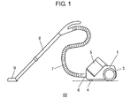
- FIG. 1 is a side view showing an outer appearance of electric vacuum cleaner 49 according to a first exemplary embodiment of the present invention.
- FIG. 2 is a cross-sectional view showing a configuration of main parts of a main body of electric vacuum cleaner 49.
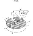
- FIG. 3 is a perspective view showing a configuration of filter 40 and dust removing unit 45 of electric vacuum cleaner 49.
- FIG. 4A is a plan view showing a configuration of filter 40 and dust removing unit 45 of electric vacuum cleaner 49.
- FIG. 4B is a cross-sectional view showing the configuration of filter 40 and dust removing unit 45 of electric vacuum cleaner 49.
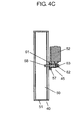
- FIG. 4C is a cross-sectional view showing the configuration of filter 40 and dust removing unit 45 of electric vacuum cleaner 49.
- wheel 3 and caster 4 are attached to an exterior of vacuum cleaner main body 1 of electric vacuum cleaner 49, so that vacuum cleaner main body 1 can freely move on a floor surface.
- Suction hose 7 and extended tube 8 are sequentially connected to suction port 6 arranged on a lower side of an installed portion of dust collecting case 5.
- Suction tool 9 is attached to a distal end of extended tube 8.
- electric blower 21 is incorporated in vacuum cleaner main body 1.
- dust collecting case 5 is detachably arranged with respect to vacuum cleaner main body 1 through partition wall 26 having ventilation port 22.
- Dust collecting case 5 introduces air containing the suctioned dust, centrifugally separates and deposits the dust, and filters the microscopic dust.
- the filter air is exhausted from an exhaust outlet (not shown) on a downstream of electric blower 21 (cyclone-type vacuum cleaner).
- Dust collecting case 5 includes dust collecting box 31 of hollow cylindrical shape having intake port 30 and being arranged on a lower side, and dust collecting lid 33 having exhaust port 32 and being arranged on the upper side. Dust collecting case 5 is configured such that intake port 30 and suction port 6 of vacuum cleaner main body 1 are communicated with each other and exhaust port 32 and ventilation port 22 of the vacuum cleaner main body 1 are communicated with each other while being attached to vacuum cleaner main body 1.
- Dust collecting box 31 internally includes middle case 34 having a shape in which a hollow cylinder and a hollow circular cone of different diameters are overlapped in multi-stages.
- Middle case 34 is configured with filter accommodation case 35, inclined tube A 36, primary filter 37, inclined tube B 38, and fine dust tube 39 continuously connected in order from the top.
- Filter accommodation case 35 has a hollow cylindrical shape and internally accommodates filter 40, and is accommodated such that an outer periphery lies along an upper end portion of an inner surface of dust collecting box 31.
- An outer surface of filter accommodation case 35 and an inner surface of dust collecting box 31 are formed so as to block a gap with a seal member (not shown).
- Inclined tube A 36 has a hollow circular cone shape, and internally includes an inclined plane for guiding the dust dropped from filter 40 to primary filter 37, inclined tube B 38, and fine dust tube 39 when removing the dust caught by filter 40.
- Primary filter 37 has a cylindrical shape with microscopic through-holes over the entire surface to pass the air from the outer periphery of the cylinder to the interior of the cylinder to filter dust (rough dust) of a relatively large size such as cotton dust and hair from the dust in suctioned airflow.
- Inclined tube B 38 has a hollow circular cone shape, similarly to inclined tube A 36, and internally includes an inclined plane for guiding the dust dropped from filter 40 to fine dust tube 39.
- Fine dust tube 39 has a hollow cylindrical shape and is provided to internally hold the dust guided from inclined tube B 38. Packing 41 for sealing a space formed with a bottom surface of fine dust tube 39 is arranged at a bottom inner surface of dust collecting box 31.
- Intake port 30 is opened such that the suctioned airflow flows in a tangent direction of the inner surface of dust collecting box 31.
- the suctioned airflow whirls in a flow path configured by a gap between the respective outer surfaces of inclined tube A 36, primary filter 37, inclined tube B 38, and fine dust tube 39, and the inner surface of dust collecting box 31.
- the suctioned airflow is ultimately suctioned into the cylinder by primary filter 37 to flow toward filter 40.
- the dust in the suctioned airflow flowing into dust collecting box 31 from intake port 30 is moved to the lower part of dust collecting box 31 while whirling so as to be pushed against the inner surface of dust collecting box 31 by a centrifugal force, and is accumulated at the bottom of dust collecting box 31.
- Canopy-like portion 42 is arranged at the lower part of primary filter 37 so that the accumulated dust is not flung up.
- the portion below canopy-like portion 42 is an accumulating portion of the dust
- the portion above canopy-like portion 42 is a centrifugal separating portion.
- Bottom lid 43 that can freely open/close is attached to the bottom of dust collecting box 31.
- the dust can be easily thrown away by opening bottom lid 43.
- the dust accumulated in fine dust tube 39 can be discarded at the same time since the bottom of fine dust tube 39 is also opened.
- Dust Majority of the dust (fine dust) that is less likely to be centrifugally separated and that has a fine particle diameter such as sand dust, pollen, mite feces, and the like is passed through primary filter 37 with an airflow to flow to filter 40.
- Such dust (fine dust) is filtered by filter 40 to be attached to and deposited on the surface of filter 40, where one part thereof entangles with the rough dust deposited at the bottom of dust collecting box 31 and accumulates thereat.
- Dust collecting lid 33 has a cylindrical shape, and is attached to an upper part of dust collecting box 31 while maintaining an airtight state. Dust collecting lid 33 internally accommodates dust removing unit 45 for removing the dust attached to filter 40 by vibration. Electrical components are accommodated in inner lid 46.
- the electrical components include a print substrate, a power supplying terminal, a charging component, a motor driver element, an ON/OFF switch, and the like. Electricity is accumulated in a charging component from vacuum cleaner main body 1 through a power supplying terminal. Dust removing unit 45 is driven by power from the charging component. Drive control of dust removing unit 45 is driven by any one of an instruction from a micro-computer (not shown) in vacuum cleaner main body 1 and an instruction from an ON/OFF switch (not shown) of dust collecting lid 33.
- dust removing unit 45 operates even in a state in which it is not connected to an electrical outlet (not shown) or in a state in which dust collecting case 5 is detached from vacuum cleaner main body 1.
- filter 40 and dust removing unit 45 will be described in detail based on FIG. 3 , FIG. 4A , FIG. 4B , and FIG. 4C .
- Dust removing unit 45 is arranged parallel to filter 40 on a downstream (upper part) of disc-shaped filter 40.
- Filter 40 may be non-woven cloth, pulp, glass fiber, or HEPA (High Efficiency Particulate Air) filter.
- PTFE PolyTetraFluoroEthylene
- Dust removing unit 45 includes driving unit 54, dust removing element 55, rail 61, and elastic member 56.
- Driving unit 54 includes electric motor 52 and regulating portion 53.
- Regulating portion 53 converts rotation of electric motor 52 to reciprocating linear driving.
- Regulating portion 53 includes eccentric cam 62, movable element 63, guide pin 64, and guide hole 65.
- Dust removing element 55 includes bone part 57, nail part 58, groove part 59, and guide blade part 60.
- Dust removing element 55 is arranged such that a longitudinal direction thereof becomes orthogonal to the tangent direction of the corrugation of filter 40.
- Elastic member 56 transmits the reciprocating driving of driving unit 54 to dust removing element 55 via two compression springs (elastic bodies).
- a plurality of nail parts 58 to be arranged in a valley of each corrugation of filter 40 are arranged on a lower side of square bar-shaped bone part 57 arranged toward a driving direction of driving unit 54 (see FIG. 4B ).
- Dust removing element 55 includes groove part 59 configured in the longitudinal direction at the middle of the upper part thereof, and includes guide blade part 60 on front and back of bone part 57. Dust removing element 55 freely moves along rail 61 by fitting guide blade part 60, in a freely slidably moving manner, to rail 61 arranged on both sides of bone part 57.
- Rail 61 is supported by inner lid 46 shown in FIG. 2 , where both ends thereof have a function of holding down and fixing frame body 51 of filter 40 from above. Furthermore, a supporting portion of electric motor 52 is also supported by inner lid 46, similarly to rail 61.
- Regulating portion 53 includes eccentric cam 62 securely arranged on a shaft center of electric motor 52, and movable element 63, inscribing eccentric cam 62, for converting the rotation to the reciprocating driving.
- Movable element 63 has one end of the lower part arranged in a freely slidably moving manner in groove part 59 of dust removing element 55, where guide pin 64 arranged to be movable in the front and back direction is fitted, in a freely slidably moving manner, to guide hole 65 formed at both ends of groove part 59 of dust removing element 55.
- the two compression springs, which are elastic bodies, of elastic member 56 are compression coil springs made of metal, and are installed in groove part 59 and biased to sandwich movable element 63.
- Elastic member 56 stretches when movable element 63 is driven in groove part 59, where the movement is transmitted to dust removing element 55 via the compression springs.
- the difference between a set length and a compressed length of the compression spring, that is, the tolerable deformation amount of the spring is desirably set to be greater than a reciprocating stroke of movable element 63. This is to prevent electric motor 52 from being locked and damaging a motor winding when dust removing element 55 stops operating due to some failure.
- eccentric cam 62 is rotated when electric motor 52 is operated.
- movable element 63 is reciprocatingly driven along groove part 59 at a stroke (e.g., 2 mm) of twice the eccentric amount (e.g., 1 mm) of electric motor 52 and eccentric cam 62.
- the compression spring expands and contracts with the motion of movable element 63, whereby a difference is generated in the biasing force of the two compression springs with respect to dust removing element 55, and dust removing element 55 is driven along rail 61.
- Nail part 58 of dust removing element 55 makes contact with the side surface of the corrugation of filter 40 to vibrate the corrugation.
- filter 40 can be efficiently vibrated since filter 40 is arranged such that the driving direction of nail part 58 is orthogonal to the corrugation of filter 40.
- Gap C is formed between nail part 58 of dust removing element 55 and film body 50 of filter 40.
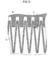
- FIG. 5 is a view describing gap C of nail part 58 of dust removing element 55 and film body 50 of filter 40 of electric vacuum cleaner 49 according to the first exemplary embodiment of the present invention.
- gap C is a gap on one side at the distal end of a surface of filter 40 and nail part 58 of dust removing element 55 when a center of a valley portion of a pleat of filter 40 coincides with a center of nail part 58.
- Gap C is a condition for dust removing element 55 to freely move and for filter 40 to not inhibit the resonance of dust removing element 55.
- about 80% (e.g., 0.8 mm) of 1/2 of the reciprocating stroke of movable element 63 is set for gap C.
- gap C is between 20% and 150% (10% to 75% of reciprocating stroke of movable element 63) of 1/2 (eccentric amount of electric motor 52 and eccentric cam 62) of the reciprocating stroke of movable element 63, dust removing element 55 resonates and a dust removing effect of filter 40 is enhanced.
- gap C is desirably between 50% and 120% (25% to 60% of reciprocating stroke of movable element 63) of 1/2 (eccentric amount of electric motor 52 and eccentric cam 62) of the reciprocating stroke of movable element 63.
- Gap C not only improves the resonance condition of dust removing element 55, but an inertia force of dust removing element 55 generated by gap C when nail part 58 makes contact with film body 50 can also act on film body 50. Thus, a strong vibration can be generated on filter 40, and the dust removing performance can be further enhanced.
- FIG. 6 is a characteristic diagram showing a temporal change in the strokes of driving unit 54 and dust removing element 55 of electric vacuum cleaner 49 according to the first exemplary embodiment of the present invention
- FIG. 7 is a view showing vibration characteristics of dust removing element 55 of electric vacuum cleaner 49.
- stroke 70 of the reciprocating driving of movable element 63 of driving unit 54 sinusoidally changes at an amplitude (2 mm) of twice the eccentric amount (1 mm in present exemplary embodiment) of electric motor 52 and eccentric cam 62.
- the period matches the rotation period of electric motor 52.
- Stroke 71 of the operation of dust removing element 55 has a period the same as the period of stroke 70 of movable element 63 of driving unit 54. However, since the compression spring is stretched and dust removing element 55 is driven, a phase is shifted by such an amount. The amplitude satisfies the resonance condition due to the arrangement of the compression spring, and the amplitude of the stroke of dust removing element 55 increases by being driven at a frequency close to resonance frequency 72, as shown in FIG. 7 . Therefore, an operation frequency of driving unit 54 is set in resonance frequency region 73 where the amplitude of stroke 71 of dust removing element 55 becomes greater than the amplitude of stroke 70 of driving unit 54.
- resonance frequency 72 is determined by the mass of vibration body and the rigidity of the spring supporting the vibration body. Resonance frequency 72 lowers when the mass becomes greater, and resonance frequency 72 rises when the rigidity of the spring becomes greater. Therefore, resonance frequency 72 is determined by the mass of dust removing element 55 and a spring constant of the compression spring. However, resonance frequency 72 changes by influential factors on resonance such as gap C of filter 40 and dust removing element 55, rigidity of filter 40, slidably moving resistance of dust removing element 55, and the like. Thus, adjustment by actual measurement is desired when setting the frequency.
- the amplitude of the reciprocating driving of dust removing element 55 is increased by the resonance action generated by the compression spring of elastic member 56 to vibrate filter 40.
- the dust removing action on filter 40 of dust removing element 55 increases, and efficient dust removal can be carried out.
- the reciprocating driving of driving unit 54 is transmitted to dust removing element 55 through elastic member 56, so that an impact noise is not generated between driving unit 54 and dust removing element 55. Therefore, electric vacuum cleaner 49 capable of removing the dust attached to filter 40 with low noise and at high efficiency can be provided.
- filter 40 of electric vacuum cleaner 49 has been described above, but the type of filter 40 of the electric vacuum cleaner of the present invention is not limited to the pleat filter described above.
- a flat plate shaped filter may be used, and effects similar to a case of using the pleat filter can be obtained as long as the vibration of dust removing element 55 is transmitted.
- a metal pressure spring is used for the elastic body of elastic member 56
- a spring made of resin may be used, or a pneumatic spring such as a bellows or a piston cylinder enclosing gas may be used.
- elastic member 56 includes a compression spring that stretches in substantially the same direction as the driving direction of driving unit 54 as an elastic body, and the power of driving unit 54 is transmitted to dust removing element 55 through the compression spring.
- a spring load and a spring constant of elastic member 56 can be arbitrarily set.
- resonance frequency 72 can also be arbitrarily set, so that a degree of freedom in design of driving unit 54 and dust removing element 55 increases.
- the compression spring itself has less variation in the spring constant and is less likely to change over the years, reliability is improved and stability is also improved.
- the frequency of dust removing element 55 is stabilized, the amplitude of dust removing element 55 is stabilized with respect to the vibration frequency of driving unit 54, and the dust removing performance can be stably obtained at high level.
- FIG. 8 is a partial cross-sectional view showing a configuration of filter 40 and dust removing unit 96 in the electric vacuum cleaner according to the second exemplary embodiment of the present invention.
- the same reference numerals are denoted on the portions same as the portions described in the first exemplary embodiment, and the descriptions thereof are omitted.
- the configuration of the entire electric vacuum cleaner according to the present exemplary embodiment is similar to the configuration of electric vacuum cleaner 49 shown in FIG. 1 and FIG. 2 .
- dust removing unit 96 of the present exemplary embodiment differs from dust removing unit 45 of the first exemplary embodiment in that a rubber member arranged in a gap in groove part 59 is used for the elastic body of elastic member 80.
- the elastic body of elastic member 80 includes two rectangular solid bodies made of rubber, and is arranged so as to sandwich movable element 63 in groove part 59.
- the rubber member stretches when movable element 63 is driven in groove part 59, so that the movement is transmitted to dust removing element 55 through elastic member 80.
- the high polymer material of the rubber member and the like has both properties of spring property and damper property for attenuating the vibration.
- a peak of the amplitude in resonance frequency 72 becomes gradual as compared to the case in which the compression spring is used for the elastic body, as shown in FIG. 7 . Therefore, the peak of the amplitude is reduced but resonance frequency region 73 is enlarged as compared to the case in which the spring is used, whereby the frequency settable range expands and the degree of freedom in design increases.
- the material itself is stretchable, the rubber can be arranged in a narrow gap, and hence the degree of freedom in arrangement increases.
- the elastic body of elastic member 80 is configured by a soft material such as rubber or elastomer, and the soft material is arranged in the gap between driving unit 54 and dust removing element 55.
- FIG. 9 is a cross-sectional view showing a configuration of filter 40 and dust removing unit 97 in the electric vacuum cleaner according to the third exemplary embodiment of the present invention
- FIG. 10 is a perspective view showing a configuration of dust removing element 85 of the electric vacuum cleaner.
- the same reference numerals are denoted on the portions same as the portions described in the first exemplary embodiment, and the descriptions thereof are omitted.
- the configuration of the entire electric vacuum cleaner according to the present exemplary embodiment is similar to the configuration of electric vacuum cleaner 49 shown in FIG. 1 and FIG. 2 .
- dust removing unit 97 of the present exemplary embodiment differs from the configuration of dust removing unit 45 of the first exemplary embodiment in that dust removing element 85, elastic member 86, movable element 87, and one part of the regulating portion (portion excluding eccentric cam 62) are integrally formed with an identical material.
- Movable element 87 is configured in a T-shape, and inscribes eccentric cam 62 in a void at the center portion to convert the rotation of eccentric cam 62 to reciprocating driving. Both end portions of the T-shape are supported by two plate spring portions 88. Plate spring portion 88 is arranged in the perpendicular direction with a lower end supported by bone part 57. Plate spring portion 88 supports movable element 87 at an upper end and is arranged such that movable element 87 is movable in the same direction as the operating direction of dust removing element 85. Plate spring portion 88 is integrally configured with dust removing element 85, where the stress on plate spring portion 88 at the time of movement is reduced by making the thickness thin (e.g., thickness of 0.3 mm). The movement of dust removing element 85 in the perpendicular direction can be suppressed by the presence of plate spring portion 88.
- a mechanism (excluding eccentric cam 62) of the regulating portion for converting the rotation of eccentric cam 62 to reciprocating driving is also integrally formed with the material identical to dust removing element 85.
- Elastic member 86 is formed in a meandering form. Elastic member 86 produces spring property by being displaced, and is arranged at two areas on both sides in the movable direction of movable element 87. One end of elastic member 86 is connected to movable element 87, and the other end is connected to the upper part of bone part 57. Thus, elastic member 86 stretches when movable element 87 is reciprocatingly driven, and the movement is transmitted to bone part 57 through elastic member 86.
- the number of components can be reduced and the manufacturing cost can be reduced (reduction in occurrence of defected article by reduction in component cost and reduction in assembly task) by integrally forming dust removing element 85, elastic member 86, and movable element 87. Furthermore, since the components are integrally formed, wear and noise between the components do not occur and positional accuracy can be improved.
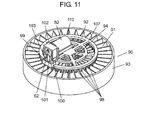
- FIG. 11 is a perspective view showing a configuration of filter 90 and dust removing unit 110 of the electric vacuum cleaner according to the fourth exemplary embodiment of the present invention
- FIG. 12A is a front view showing a configuration of filter 90 and dust removing unit 110 of the electric vacuum cleaner
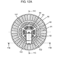
- FIG. 12B is a cross-sectional view showing a configuration of filter 90 and dust removing unit 110 of the electric vacuum cleaner
- FIG. 12C is a cross-sectional view showing a configuration of filter 90 and dust removing unit 110 of the electric vacuum cleaner.
- the same reference numerals are denoted on the portions same as the portions described in the first exemplary embodiment, and the descriptions thereof are omitted.
- the configuration of the entire electric vacuum cleaner according to the present exemplary embodiment is similar to the configuration of electric vacuum cleaner 49 shown in FIG. 1 and FIG. 2 .
- the present exemplary embodiment differs from the first exemplary embodiment in that film body 91 of filter 90 is not parallel corrugated and has one end of the corrugation spread in a disc shape, and in that dust removing element 92 is formed in a circular shape in accordance with the configuration of the corrugation of film body 91.
- the details will be described below.
- Filter 90 is integrally molded with resin such that film body 91, in which one end of the corrugation is spread to a disc shape and ridge lines of the corrugation are radially formed, is sandwiched between outer frame body 93 and inner frame body 94 of cylindrical shape. Bearing hole 95 is formed at the center of inner frame body 94.
- Dust removing element 92 has shaft part 106 fitted to bearing hole 95 arranged at the center, and circular bone part 107 having shaft part 106 as center is formed.
- a plurality of nail parts 98 to be arranged in a valley of each corrugation of filter 90 are radially arranged on a lower side of circular bone part 107. That is, nail part 98 is configured to be freely turnable in an arcuate form with shaft part 106 as the center.
- Groove part 99 is arranged in a tangent direction of a circle of bone part 107 at one area on an upper side of bone part 107 (see FIG. 11 ).
- Regulating portion 100 includes eccentric cam 62 securely arranged at the shaft center of electric motor 52, and movable element 101, inscribed to eccentric cam 62, for converting the rotation to reciprocating driving.
- Movable element 101 is configured with one end of the lower part arranged in groove part 99 of dust removing element 92 and so that the driving direction of movable element 101 coincides with the tangent direction of the circle of bone part 107.
- Movable element 101 is supported by guide 102 in a slidably moving manner with the driving direction as the horizontal left and right direction. Movable element 101 is controlled such that the reciprocating driving becomes linear.
- Guide 102 also supports electric motor 52, and is supported by inner lid 46 shown in FIG. 2 .
- Elastic member 103 includes a rectangular solid body made of rubber as an elastic body. Elastic member 103 is arranged in groove part 99, and has a hole on the upper side from the middle. One end at the lower part of movable element 101 is inserted to the hole. Elastic member 103 thus stretches when movable element 101 is driven in groove part 99, and the movement is transmitted to dust removing element 92.
- Gap C is formed between nail part 98 of dust removing element 92 and film body 91 of filter 90. Gap C is an important condition for dust removing element 92 to freely move and for filter 90 not to inhibit the resonance of dust removing element 92. In the present exemplary embodiment, about 80% (e.g., 0.8 mm) of 1/2 of the reciprocating stroke of movable element 101 is set as gap C. If gap C is between 20% and 150% (10% to 75% of reciprocating stroke of movable element 101) of 1/2 (eccentric amount of electric motor 52 and eccentric cam 62) of the reciprocating stroke of movable element 101, dust removing element 92 resonates and the dust removing effect of filter 90 is enhanced.
- gap C is desirably between 50% and 120% (25% to 60% of reciprocating stroke of movable element 101) of 1/2 (eccentric amount of electric motor 52 and eccentric cam 62) of the reciprocating stroke of movable element 101.
- Gap C not only improves the resonance condition of dust removing element 92, but an inertia force of dust removing element 92 generated by gap C when nail part 98 makes contact with film body 91 can also act on film body 91. Thus, a strong vibration can be generated on filter 90, thus further improving the dust removing performance.
- the reciprocating driving by electric motor 52 is transmitted to dust removing element 92 through elastic member 103, so that an impact noise is not generated between movable element 101 and dust removing element 55. Therefore, an electric vacuum cleaner capable of removing the dust attached to filter 90 with low noise and at high efficiency can be provided.
- the reciprocating vibration of movable element 101 can be transmitted to dust removing element 92 through elastic member 103 even if the ridge line direction of the corrugation of filter 90 is radial and the reciprocating vibration direction of dust removing element 92 is arcuate. Therefore, the resonance condition is satisfied in dust removing element 92.
- the amplitude of dust removing element 92 increases by the resonance action, and the dust removing effect on filter 90 can be enhanced.
- the driving of the driving unit is transmitted to the dust removing element through the elastic member in the electric vacuum cleaner of each exemplary embodiment.
- the resonance condition is satisfied mainly by the spring constant of the elastic member and the weight of the dust removing element, and the amplitude of the dust removing element can be increased by approaching the frequency of the driving unit closer to the resonance frequency. Therefore, the filter arranged close to the dust removing element can greatly vibrate, and the dust can be efficiently removed.
- the reciprocating driving of the driving unit is transmitted to the dust removing element through the elastic body, the impact noise is not generated between the driving unit and the dust removing element.
- an electric vacuum cleaner capable of removing the dust attached to the filter with low noise and at high efficiency can be provided.
- gap C is arranged between the dust removing element and the filter, and gap C is set in a predetermined range with respect to 1/2 of the reciprocating driving amplitude of the driving unit.
- the filter carries out an attenuating action on the resonance operation of the dust removing element, and thus the influence on the resonance operation of the dust removing element can be reduced by providing gap C.
- gap C between the dust removing element and the filter.
- gap C from 20% to 150% of 1/2 of the reciprocating driving amplitude of the driving unit is provided, where 50% to 120% is a more preferable condition.
- This is a condition in which the resonance of the dust removing element is not inhibited by the filter, and the dust removing element makes contact with the filter to enhance the dust removing effect.
- the driving unit preferably includes a motor, which is electrically rotated, and a regulating portion for converting the rotation of the motor to the reciprocating linear driving, and the tolerable deformation amount of the elastic member produced by the driving deviation of the driving unit and the dust removing element is preferably greater than the reciprocating driving amount of the regulating portion.
- the tolerable deformation amount of the elastic member is greater than the reciprocating driving amount of the converting portion, and the motor can be rotated without being locked and the abnormal heat generation by the overcurrent of the motor can be prevented even if the dust removing element is stopped, for example.
- the dust attached to the filter can be removed with low noise and at high efficiency using the resonance action, and hence it is useful as an electric vacuum cleaner equipped with a filter for filtering dust, and the like.
Abstract
Description
- The present invention relates to an electric vacuum cleaner equipped with a filter for filtering dust.
- Conventionally, a method of applying vibration to a filter to remove dust has been proposed as means for preventing the filter from getting clogged in the field of electric vacuum cleaner. For example, there has been proposed a vacuum cleaner including a dust removing unit for vibrating a plurality of nail parts fitted to each corrugation in a filter in which a cross-section is bent in a wave form to form a plurality of corrugations (see e.g., Patent Literature 1).
-
FIG. 13 is a schematic view showing a schematic configuration of conventionalelectric vacuum cleaner 1000.FIG. 14 is a perspective view showing a configuration offilter device 1111 in conventionalelectric vacuum cleaner 1000. - As shown in
FIG. 13 and FIG. 14 ,electric vacuum cleaner 1000 includesfilter device 1111 for catching dust suctioned byelectric blower 1110, andvibrator 1112 for vibratingfilter device 1111.Filter device 1111 is vibrated by vibrator 1112 to remove the dust caught byfilter device 1111 before driving of or after driving ofelectric blower 1110. -
Filter device 1111 includessquare casing frame 1113,sheet body 1116, andvibration transmitting member 1117.Sheet body 1116 is internally arranged incasing frame 1113, and is formed with a plurality ofprojections 1114 andrecesses 1115 by being bent in a wavelike form.Vibration transmitting member 1117 transmits vibration ofvibrator 1112 tosheet body 1116. - Vibrator 1112 internally includes a vibration motor, and is arranged next to
filter device 1111. -
Vibration transmitting member 1117 includes a plurality ofnail parts 1118 fitted to each one of the plurality ofrecesses 1115 ofsheet body 1116, and transmittingprojection 1119 for directly receiving the vibration fromvibrator 1112. - The vibration of
vibrator 1112 is transmitted from transmittingprojection 1119 tovibration transmitting member 1117, and such vibration is transmitted fromnail parts 1118 tosheet body 1116. Accordingly, the dust caught bysheet body 1116 can be removed. - In such conventional
electric vacuum cleaner 1000, however, improvements still can be made in higher efficiency of the dust removing performance and lower noise. - In other words,
vibrator 1112 is arranged next tofilter device 1111 in conventionalelectric vacuum cleaner 1000, as described above. The vibration ofvibrator 1112 thus tends to vibrateentire filter device 1111 at the same time as vibrating transmittingprojection 1119. Therefore, vibration energy ofvibrator 1112 is diffused not only tofilter device 1111, but also to entireelectric vacuum cleaner 1000 supportingfilter device 1111. - Furthermore, as described above, the vibration from
vibrator 1112 is transmitted to transmittingprojection 1119 ofvibration transmitting member 1117 to vibratenail parts 1118, and then transmitted tosheet body 1116. Thus, a transmission loss until the vibration ofvibrator 1112 is transmitted tosheet body 1116 is large, and the vibration tends to attenuate. - Therefore, in order to vibrate
sheet body 1116 and realize sufficient dust removing performance, an output of a vibration generating source needs to be raised, which inevitably enlargesvibrator 1112. - Furthermore, since transmitting
projection 1119 ofvibration transmitting member 1117 directly receives the vibration ofvibrator 1112, an impact noise is generated thus generating noise. -
- PTL 1: Japanese Unexamined Patent Publication No.
2004-121621 - The present invention provides an electric vacuum cleaner in which dust attached to a filter is removed with low noise and at high efficiency.
- An electric vacuum cleaner according to the present invention includes an electric blower; a filter for catching dust suctioned by the electric blower; and a dust removing unit for removing the dust attached to the filter. The dust removing unit includes a driving unit including a regulating portion for linear driving, and being adapted to reciprocatingly drive, a dust removing element being arranged close to the filter and being movable in a direction substantially identical to a direction of the reciprocating driving of the driving unit, and an elastic member being adapted to transmit the reciprocating driving of the driving unit to the dust removing element through an elastic body. An amplitude of the reciprocating driving of the dust removing element is increased by a resonance action generated by the elastic member to vibrate the filter.
-
-
FIG. 1 is a side view showing an outer appearance of an electric vacuum cleaner according to a first exemplary embodiment of the present invention. -
FIG. 2 is a cross-sectional view showing a configuration of main parts of a main body of the electric vacuum cleaner according to the first exemplary embodiment of the present invention. -
FIG. 3 is a perspective view showing a configuration of a filter and a dust removing unit of the electric vacuum cleaner according to the first exemplary embodiment of the present invention. -
FIG. 4A is a plan view showing a configuration of the filter and the dust removing unit of the electric vacuum cleaner according to the first exemplary embodiment of the present invention. -
FIG. 4B is a cross-sectional view showing the configuration of the filter and the dust removing unit of the electric vacuum cleaner according to the first exemplary embodiment of the present invention. -
FIG. 4C is a cross-sectional view showing the configuration of the filter and the dust removing unit of the electric vacuum cleaner according to the first exemplary embodiment of the present invention. -
FIG. 5 is a view describing gap C of a nail part of a dust removing element and a film body of the filter of the electric vacuum cleaner according to the first exemplary embodiment of the present invention. -
FIG. 6 is a characteristic diagram showing a temporal change in strokes of a driving unit and the dust removing element of the electric vacuum cleaner according to the first exemplary embodiment of the present invention. -
FIG. 7 is a view showing vibration characteristics of the dust removing element of the electric vacuum cleaner according to the first exemplary embodiment of the present invention. -
FIG. 8 is a partial cross-sectional view showing a configuration of a filter and a dust removing unit in an electric vacuum cleaner according to a second exemplary embodiment of the present invention. -
FIG. 9 is a cross-sectional view showing a configuration of a filter and a dust removing unit in an electric vacuum cleaner according to a third exemplary embodiment of the present invention. -
FIG. 10 is a perspective view showing a configuration of a dust removing element in the electric vacuum cleaner according to the third exemplary embodiment of the present invention. -
FIG. 11 is a perspective view showing a configuration of a filter and a dust removing unit of an electric vacuum cleaner according to a fourth exemplary embodiment of the present invention. -
FIG. 12A is a front view showing a configuration of the filter and the dust removing unit of the electric vacuum cleaner according to the fourth exemplary embodiment of the present invention. -
FIG. 12B is a cross-sectional view showing the configuration of the filter and the dust removing unit of the electric vacuum cleaner according to the fourth exemplary embodiment of the present invention. -
FIG. 12C is a cross-sectional view showing the configuration of the filter and the dust removing unit of the electric vacuum cleaner according to the fourth exemplary embodiment of the present invention. -
FIG. 13 is a schematic view showing a schematic configuration of a conventional electric vacuum cleaner. -
FIG. 14 is a perspective view showing a configuration of a filter device in the conventional electric vacuum cleaner. - Hereinafter, exemplary embodiments of the present invention will be described with reference to the drawings. The same reference numerals may be denoted on the same or corresponding portions to omit the redundant description.
-
FIG. 1 is a side view showing an outer appearance ofelectric vacuum cleaner 49 according to a first exemplary embodiment of the present invention.FIG. 2 is a cross-sectional view showing a configuration of main parts of a main body ofelectric vacuum cleaner 49.FIG. 3 is a perspective view showing a configuration offilter 40 anddust removing unit 45 ofelectric vacuum cleaner 49.FIG. 4A is a plan view showing a configuration offilter 40 anddust removing unit 45 ofelectric vacuum cleaner 49.FIG. 4B is a cross-sectional view showing the configuration offilter 40 anddust removing unit 45 ofelectric vacuum cleaner 49.FIG. 4C is a cross-sectional view showing the configuration offilter 40 anddust removing unit 45 ofelectric vacuum cleaner 49. - As shown in
FIG. 1 ,wheel 3 andcaster 4 are attached to an exterior of vacuum cleanermain body 1 ofelectric vacuum cleaner 49, so that vacuum cleanermain body 1 can freely move on a floor surface.Suction hose 7 andextended tube 8 are sequentially connected tosuction port 6 arranged on a lower side of an installed portion ofdust collecting case 5.Suction tool 9 is attached to a distal end ofextended tube 8. - As shown in
FIG. 2 ,electric blower 21 is incorporated in vacuum cleanermain body 1. On an upstream side ofelectric blower 21,dust collecting case 5 is detachably arranged with respect to vacuum cleanermain body 1 throughpartition wall 26 havingventilation port 22. By operatingelectric blower 21, dust on a floor surface of a house can be suctioned into vacuum cleanermain body 1. Dust collectingcase 5 introduces air containing the suctioned dust, centrifugally separates and deposits the dust, and filters the microscopic dust. The filter air is exhausted from an exhaust outlet (not shown) on a downstream of electric blower 21 (cyclone-type vacuum cleaner). - Dust collecting
case 5 includesdust collecting box 31 of hollow cylindrical shape havingintake port 30 and being arranged on a lower side, anddust collecting lid 33 havingexhaust port 32 and being arranged on the upper side. Dust collectingcase 5 is configured such thatintake port 30 andsuction port 6 of vacuum cleanermain body 1 are communicated with each other andexhaust port 32 andventilation port 22 of the vacuum cleanermain body 1 are communicated with each other while being attached to vacuum cleanermain body 1. -
Dust collecting box 31 internally includesmiddle case 34 having a shape in which a hollow cylinder and a hollow circular cone of different diameters are overlapped in multi-stages.Middle case 34 is configured withfilter accommodation case 35,inclined tube A 36,primary filter 37,inclined tube B 38, andfine dust tube 39 continuously connected in order from the top. -
Filter accommodation case 35 has a hollow cylindrical shape and internally accommodatesfilter 40, and is accommodated such that an outer periphery lies along an upper end portion of an inner surface ofdust collecting box 31. An outer surface offilter accommodation case 35 and an inner surface ofdust collecting box 31 are formed so as to block a gap with a seal member (not shown). -
Inclined tube A 36 has a hollow circular cone shape, and internally includes an inclined plane for guiding the dust dropped fromfilter 40 toprimary filter 37,inclined tube B 38, andfine dust tube 39 when removing the dust caught byfilter 40. -
Primary filter 37 has a cylindrical shape with microscopic through-holes over the entire surface to pass the air from the outer periphery of the cylinder to the interior of the cylinder to filter dust (rough dust) of a relatively large size such as cotton dust and hair from the dust in suctioned airflow. -
Inclined tube B 38 has a hollow circular cone shape, similarly toinclined tube A 36, and internally includes an inclined plane for guiding the dust dropped fromfilter 40 tofine dust tube 39. -
Fine dust tube 39 has a hollow cylindrical shape and is provided to internally hold the dust guided frominclined tube B 38.Packing 41 for sealing a space formed with a bottom surface offine dust tube 39 is arranged at a bottom inner surface ofdust collecting box 31. -
Intake port 30 is opened such that the suctioned airflow flows in a tangent direction of the inner surface ofdust collecting box 31. The suctioned airflow whirls in a flow path configured by a gap between the respective outer surfaces ofinclined tube A 36,primary filter 37,inclined tube B 38, andfine dust tube 39, and the inner surface ofdust collecting box 31. The suctioned airflow is ultimately suctioned into the cylinder byprimary filter 37 to flow towardfilter 40. - The dust in the suctioned airflow flowing into
dust collecting box 31 fromintake port 30 is moved to the lower part ofdust collecting box 31 while whirling so as to be pushed against the inner surface ofdust collecting box 31 by a centrifugal force, and is accumulated at the bottom ofdust collecting box 31. Canopy-like portion 42 is arranged at the lower part ofprimary filter 37 so that the accumulated dust is not flung up. In other words, the portion below canopy-like portion 42 is an accumulating portion of the dust, and the portion above canopy-like portion 42 is a centrifugal separating portion. -
Bottom lid 43 that can freely open/close is attached to the bottom ofdust collecting box 31. When discarding the dust accumulated indust collecting box 31, the dust can be easily thrown away by openingbottom lid 43. Furthermore, the dust accumulated infine dust tube 39 can be discarded at the same time since the bottom offine dust tube 39 is also opened. - Majority of the dust (fine dust) that is less likely to be centrifugally separated and that has a fine particle diameter such as sand dust, pollen, mite feces, and the like is passed through
primary filter 37 with an airflow to flow to filter 40. Such dust (fine dust) is filtered byfilter 40 to be attached to and deposited on the surface offilter 40, where one part thereof entangles with the rough dust deposited at the bottom ofdust collecting box 31 and accumulates thereat. -
Dust collecting lid 33 has a cylindrical shape, and is attached to an upper part ofdust collecting box 31 while maintaining an airtight state.Dust collecting lid 33 internally accommodatesdust removing unit 45 for removing the dust attached to filter 40 by vibration. Electrical components are accommodated ininner lid 46. - The electrical components include a print substrate, a power supplying terminal, a charging component, a motor driver element, an ON/OFF switch, and the like. Electricity is accumulated in a charging component from vacuum cleaner
main body 1 through a power supplying terminal.Dust removing unit 45 is driven by power from the charging component. Drive control ofdust removing unit 45 is driven by any one of an instruction from a micro-computer (not shown) in vacuum cleanermain body 1 and an instruction from an ON/OFF switch (not shown) ofdust collecting lid 33. - Thus, due to the operation of the charging component,
dust removing unit 45 operates even in a state in which it is not connected to an electrical outlet (not shown) or in a state in whichdust collecting case 5 is detached from vacuum cleanermain body 1. - Next, the configuration of
filter 40 anddust removing unit 45 will be described in detail based onFIG. 3 ,FIG. 4A ,FIG. 4B , andFIG. 4C . -
Dust removing unit 45 is arranged parallel to filter 40 on a downstream (upper part) of disc-shapedfilter 40. -
Filter 40 may be non-woven cloth, pulp, glass fiber, or HEPA (High Efficiency Particulate Air) filter. In the present exemplary embodiment,film body 50 formed by folding a filtering film, in which a PTFE (PolyTetraFluoroEthylene) film excelling in dust separating property is stacked on a non-woven cloth, in a wave form to form corrugations is integrally molded with resin on the inner side ofcylindrical frame body 51. -
Dust removing unit 45 includes drivingunit 54,dust removing element 55,rail 61, andelastic member 56. Drivingunit 54 includeselectric motor 52 and regulatingportion 53. Regulatingportion 53 converts rotation ofelectric motor 52 to reciprocating linear driving. Regulatingportion 53 includeseccentric cam 62,movable element 63,guide pin 64, and guidehole 65. Dust removingelement 55 includesbone part 57,nail part 58,groove part 59, and guideblade part 60. - Dust removing
element 55 is arranged such that a longitudinal direction thereof becomes orthogonal to the tangent direction of the corrugation offilter 40.Elastic member 56 transmits the reciprocating driving of drivingunit 54 to dust removingelement 55 via two compression springs (elastic bodies). - A plurality of
nail parts 58 to be arranged in a valley of each corrugation offilter 40 are arranged on a lower side of square bar-shapedbone part 57 arranged toward a driving direction of driving unit 54 (seeFIG. 4B ). Dust removingelement 55 includesgroove part 59 configured in the longitudinal direction at the middle of the upper part thereof, and includesguide blade part 60 on front and back ofbone part 57. Dust removingelement 55 freely moves alongrail 61 by fittingguide blade part 60, in a freely slidably moving manner, to rail 61 arranged on both sides ofbone part 57. -
Rail 61 is supported byinner lid 46 shown inFIG. 2 , where both ends thereof have a function of holding down and fixingframe body 51 offilter 40 from above. Furthermore, a supporting portion ofelectric motor 52 is also supported byinner lid 46, similarly torail 61. - Regulating
portion 53 includeseccentric cam 62 securely arranged on a shaft center ofelectric motor 52, andmovable element 63, inscribingeccentric cam 62, for converting the rotation to the reciprocating driving.Movable element 63 has one end of the lower part arranged in a freely slidably moving manner ingroove part 59 ofdust removing element 55, whereguide pin 64 arranged to be movable in the front and back direction is fitted, in a freely slidably moving manner, to guidehole 65 formed at both ends ofgroove part 59 ofdust removing element 55. - The two compression springs, which are elastic bodies, of
elastic member 56 are compression coil springs made of metal, and are installed ingroove part 59 and biased to sandwichmovable element 63.Elastic member 56 stretches whenmovable element 63 is driven ingroove part 59, where the movement is transmitted to dust removingelement 55 via the compression springs. - The difference between a set length and a compressed length of the compression spring, that is, the tolerable deformation amount of the spring is desirably set to be greater than a reciprocating stroke of
movable element 63. This is to preventelectric motor 52 from being locked and damaging a motor winding whendust removing element 55 stops operating due to some failure. - In the above configuration,
eccentric cam 62 is rotated whenelectric motor 52 is operated. Thus,movable element 63 is reciprocatingly driven alonggroove part 59 at a stroke (e.g., 2 mm) of twice the eccentric amount (e.g., 1 mm) ofelectric motor 52 andeccentric cam 62. The compression spring expands and contracts with the motion ofmovable element 63, whereby a difference is generated in the biasing force of the two compression springs with respect to dust removingelement 55, anddust removing element 55 is driven alongrail 61.Nail part 58 ofdust removing element 55 makes contact with the side surface of the corrugation offilter 40 to vibrate the corrugation. - In this case,
dust removing element 55 andmovable element 63 move in the same linear direction, and the compression spring also expands and contracts in the same direction, and hence the direction of driving coincides and the transmission loss is reduced. Furthermore, filter 40 can be efficiently vibrated sincefilter 40 is arranged such that the driving direction ofnail part 58 is orthogonal to the corrugation offilter 40. - Gap C is formed between
nail part 58 ofdust removing element 55 andfilm body 50 offilter 40. -
FIG. 5 is a view describing gap C ofnail part 58 ofdust removing element 55 andfilm body 50 offilter 40 ofelectric vacuum cleaner 49 according to the first exemplary embodiment of the present invention. As shown inFIG. 5 , gap C is a gap on one side at the distal end of a surface offilter 40 and nailpart 58 ofdust removing element 55 when a center of a valley portion of a pleat offilter 40 coincides with a center ofnail part 58. Gap C is a condition fordust removing element 55 to freely move and forfilter 40 to not inhibit the resonance ofdust removing element 55. In the present exemplary embodiment, about 80% (e.g., 0.8 mm) of 1/2 of the reciprocating stroke ofmovable element 63 is set for gap C. If gap C is between 20% and 150% (10% to 75% of reciprocating stroke of movable element 63) of 1/2 (eccentric amount ofelectric motor 52 and eccentric cam 62) of the reciprocating stroke ofmovable element 63,dust removing element 55 resonates and a dust removing effect offilter 40 is enhanced. In order to further enhance the effect, gap C is desirably between 50% and 120% (25% to 60% of reciprocating stroke of movable element 63) of 1/2 (eccentric amount ofelectric motor 52 and eccentric cam 62) of the reciprocating stroke ofmovable element 63. - Gap C not only improves the resonance condition of
dust removing element 55, but an inertia force ofdust removing element 55 generated by gap C whennail part 58 makes contact withfilm body 50 can also act onfilm body 50. Thus, a strong vibration can be generated onfilter 40, and the dust removing performance can be further enhanced. - Next, the dust removing operation will be described with reference to
FIG. 6 and FIG. 7. FIG. 6 is a characteristic diagram showing a temporal change in the strokes of drivingunit 54 anddust removing element 55 ofelectric vacuum cleaner 49 according to the first exemplary embodiment of the present invention, andFIG. 7 is a view showing vibration characteristics ofdust removing element 55 ofelectric vacuum cleaner 49. - As shown in
FIG. 6 ,stroke 70 of the reciprocating driving ofmovable element 63 of drivingunit 54 sinusoidally changes at an amplitude (2 mm) of twice the eccentric amount (1 mm in present exemplary embodiment) ofelectric motor 52 andeccentric cam 62. The period matches the rotation period ofelectric motor 52. -
Stroke 71 of the operation ofdust removing element 55 has a period the same as the period ofstroke 70 ofmovable element 63 of drivingunit 54. However, since the compression spring is stretched anddust removing element 55 is driven, a phase is shifted by such an amount. The amplitude satisfies the resonance condition due to the arrangement of the compression spring, and the amplitude of the stroke ofdust removing element 55 increases by being driven at a frequency close toresonance frequency 72, as shown inFIG. 7 . Therefore, an operation frequency of drivingunit 54 is set inresonance frequency region 73 where the amplitude ofstroke 71 ofdust removing element 55 becomes greater than the amplitude ofstroke 70 of drivingunit 54. - Generally,
resonance frequency 72 is determined by the mass of vibration body and the rigidity of the spring supporting the vibration body.Resonance frequency 72 lowers when the mass becomes greater, andresonance frequency 72 rises when the rigidity of the spring becomes greater. Therefore,resonance frequency 72 is determined by the mass ofdust removing element 55 and a spring constant of the compression spring. However,resonance frequency 72 changes by influential factors on resonance such as gap C offilter 40 anddust removing element 55, rigidity offilter 40, slidably moving resistance ofdust removing element 55, and the like. Thus, adjustment by actual measurement is desired when setting the frequency. - As described above, in the present exemplary embodiment, the amplitude of the reciprocating driving of
dust removing element 55 is increased by the resonance action generated by the compression spring ofelastic member 56 to vibratefilter 40. Thus, the dust removing action onfilter 40 ofdust removing element 55 increases, and efficient dust removal can be carried out. - In the present exemplary embodiment, the reciprocating driving of driving
unit 54 is transmitted to dust removingelement 55 throughelastic member 56, so that an impact noise is not generated between drivingunit 54 anddust removing element 55. Therefore,electric vacuum cleaner 49 capable of removing the dust attached to filter 40 with low noise and at high efficiency can be provided. - The configuration and the effects of
filter 40 ofelectric vacuum cleaner 49 according to the present exemplary embodiment has been described above, but the type offilter 40 of the electric vacuum cleaner of the present invention is not limited to the pleat filter described above. For example, a flat plate shaped filter may be used, and effects similar to a case of using the pleat filter can be obtained as long as the vibration ofdust removing element 55 is transmitted. - In the present exemplary embodiment, an example of using
electric motor 52 andeccentric cam 62 for the configuration of drivingunit 54 has been described, but means capable of linear reciprocating driving such as a linear motor may be used. - Furthermore, in the present exemplary embodiment, an example in which a metal pressure spring is used for the elastic body of
elastic member 56 has been described, but a spring made of resin may be used, or a pneumatic spring such as a bellows or a piston cylinder enclosing gas may be used. - In the present exemplary embodiment, an example has been described in which a configuration of converting the rotation of
electric motor 52 to reciprocating driving bymovable element 63 inscribed toeccentric cam 62 is used for the configuration of regulatingportion 53. However, the configuration of the regulating portion of the electric vacuum cleaner of the present invention is not limited to such an example. For example, the rotation ofelectric motor 52 may be converted to the reciprocating driving by a crank shaft and a connecting rod to movemovable element 63. - Moreover, in the present exemplary embodiment,
elastic member 56 includes a compression spring that stretches in substantially the same direction as the driving direction of drivingunit 54 as an elastic body, and the power of drivingunit 54 is transmitted to dust removingelement 55 through the compression spring. - According to such a configuration, a spring load and a spring constant of
elastic member 56 can be arbitrarily set. Thus,resonance frequency 72 can also be arbitrarily set, so that a degree of freedom in design of drivingunit 54 anddust removing element 55 increases. - Furthermore, more efficient dust removal can be realized by bringing the resonance frequency of the corrugation itself of
filter 40 close to the frequency ofdust removing element 55. - As the compression spring itself has less variation in the spring constant and is less likely to change over the years, reliability is improved and stability is also improved. As the frequency of
dust removing element 55 is stabilized, the amplitude ofdust removing element 55 is stabilized with respect to the vibration frequency of drivingunit 54, and the dust removing performance can be stably obtained at high level. - A configuration of
dust removing unit 96 in an electric vacuum cleaner according to a second exemplary embodiment of the present invention will be described in detail with reference to the drawings.FIG. 8 is a partial cross-sectional view showing a configuration offilter 40 anddust removing unit 96 in the electric vacuum cleaner according to the second exemplary embodiment of the present invention. The same reference numerals are denoted on the portions same as the portions described in the first exemplary embodiment, and the descriptions thereof are omitted. The configuration of the entire electric vacuum cleaner according to the present exemplary embodiment is similar to the configuration ofelectric vacuum cleaner 49 shown inFIG. 1 andFIG. 2 . - As shown in
FIG. 8 ,dust removing unit 96 of the present exemplary embodiment differs fromdust removing unit 45 of the first exemplary embodiment in that a rubber member arranged in a gap ingroove part 59 is used for the elastic body ofelastic member 80. The elastic body ofelastic member 80 includes two rectangular solid bodies made of rubber, and is arranged so as to sandwichmovable element 63 ingroove part 59. Thus, the rubber member stretches whenmovable element 63 is driven ingroove part 59, so that the movement is transmitted to dust removingelement 55 throughelastic member 80. - The high polymer material of the rubber member and the like has both properties of spring property and damper property for attenuating the vibration. Thus, if the elastic body of
elastic member 80 is made of rubber, a peak of the amplitude inresonance frequency 72 becomes gradual as compared to the case in which the compression spring is used for the elastic body, as shown inFIG. 7 . Therefore, the peak of the amplitude is reduced butresonance frequency region 73 is enlarged as compared to the case in which the spring is used, whereby the frequency settable range expands and the degree of freedom in design increases. Furthermore, since the material itself is stretchable, the rubber can be arranged in a narrow gap, and hence the degree of freedom in arrangement increases. - In the present exemplary embodiment, an example in which the rubber is used for the material of the elastic body of
elastic member 80 has been described, but a soft material such as elastomer or foam resin may be used. Furthermore, in the present exemplary embodiment, an example in which twoelastic members 80 are used has been described, butmovable element 63 may be arranged at the middle of singleelastic member 80. - In the present exemplary embodiment, from the viewpoint of easy production and longer lifespan of
filter 40, the elastic body ofelastic member 80 is configured by a soft material such as rubber or elastomer, and the soft material is arranged in the gap between drivingunit 54 anddust removing element 55. - A configuration of
dust removing unit 97 in an electric vacuum cleaner according to a third exemplary embodiment of the present invention will be described in detail with reference to the drawings.FIG. 9 is a cross-sectional view showing a configuration offilter 40 anddust removing unit 97 in the electric vacuum cleaner according to the third exemplary embodiment of the present invention, andFIG. 10 is a perspective view showing a configuration ofdust removing element 85 of the electric vacuum cleaner. The same reference numerals are denoted on the portions same as the portions described in the first exemplary embodiment, and the descriptions thereof are omitted. The configuration of the entire electric vacuum cleaner according to the present exemplary embodiment is similar to the configuration ofelectric vacuum cleaner 49 shown inFIG. 1 andFIG. 2 . - As shown in
FIG. 9 and FIG. 10 ,dust removing unit 97 of the present exemplary embodiment differs from the configuration ofdust removing unit 45 of the first exemplary embodiment in thatdust removing element 85,elastic member 86,movable element 87, and one part of the regulating portion (portion excluding eccentric cam 62) are integrally formed with an identical material. -
Movable element 87 is configured in a T-shape, and inscribeseccentric cam 62 in a void at the center portion to convert the rotation ofeccentric cam 62 to reciprocating driving. Both end portions of the T-shape are supported by twoplate spring portions 88.Plate spring portion 88 is arranged in the perpendicular direction with a lower end supported bybone part 57.Plate spring portion 88 supportsmovable element 87 at an upper end and is arranged such thatmovable element 87 is movable in the same direction as the operating direction ofdust removing element 85.Plate spring portion 88 is integrally configured withdust removing element 85, where the stress onplate spring portion 88 at the time of movement is reduced by making the thickness thin (e.g., thickness of 0.3 mm). The movement ofdust removing element 85 in the perpendicular direction can be suppressed by the presence ofplate spring portion 88. - Therefore, a mechanism (excluding eccentric cam 62) of the regulating portion for converting the rotation of
eccentric cam 62 to reciprocating driving is also integrally formed with the material identical to dust removingelement 85. -
Elastic member 86 is formed in a meandering form.Elastic member 86 produces spring property by being displaced, and is arranged at two areas on both sides in the movable direction ofmovable element 87. One end ofelastic member 86 is connected tomovable element 87, and the other end is connected to the upper part ofbone part 57. Thus,elastic member 86 stretches whenmovable element 87 is reciprocatingly driven, and the movement is transmitted tobone part 57 throughelastic member 86. - As described above, according to the present exemplary embodiment, the number of components can be reduced and the manufacturing cost can be reduced (reduction in occurrence of defected article by reduction in component cost and reduction in assembly task) by integrally forming
dust removing element 85,elastic member 86, andmovable element 87. Furthermore, since the components are integrally formed, wear and noise between the components do not occur and positional accuracy can be improved. -
Filter 90 anddust removing unit 110 in an electric vacuum cleaner according to a fourth exemplary embodiment of the present invention will be described in detail with reference to the drawings. -
FIG. 11 is a perspective view showing a configuration offilter 90 anddust removing unit 110 of the electric vacuum cleaner according to the fourth exemplary embodiment of the present invention,FIG. 12A is a front view showing a configuration offilter 90 anddust removing unit 110 of the electric vacuum cleaner,FIG. 12B is a cross-sectional view showing a configuration offilter 90 anddust removing unit 110 of the electric vacuum cleaner, andFIG. 12C is a cross-sectional view showing a configuration offilter 90 anddust removing unit 110 of the electric vacuum cleaner. The same reference numerals are denoted on the portions same as the portions described in the first exemplary embodiment, and the descriptions thereof are omitted. The configuration of the entire electric vacuum cleaner according to the present exemplary embodiment is similar to the configuration ofelectric vacuum cleaner 49 shown inFIG. 1 andFIG. 2 . - As shown in
FIG. 11 , andFIG. 12A toFIG. 12C , the present exemplary embodiment differs from the first exemplary embodiment in thatfilm body 91 offilter 90 is not parallel corrugated and has one end of the corrugation spread in a disc shape, and in thatdust removing element 92 is formed in a circular shape in accordance with the configuration of the corrugation offilm body 91. The details will be described below. -
Filter 90 is integrally molded with resin such thatfilm body 91, in which one end of the corrugation is spread to a disc shape and ridge lines of the corrugation are radially formed, is sandwiched betweenouter frame body 93 andinner frame body 94 of cylindrical shape. Bearinghole 95 is formed at the center ofinner frame body 94. - Dust removing
element 92 hasshaft part 106 fitted to bearinghole 95 arranged at the center, andcircular bone part 107 havingshaft part 106 as center is formed. A plurality ofnail parts 98 to be arranged in a valley of each corrugation offilter 90 are radially arranged on a lower side ofcircular bone part 107. That is,nail part 98 is configured to be freely turnable in an arcuate form withshaft part 106 as the center. Groovepart 99 is arranged in a tangent direction of a circle ofbone part 107 at one area on an upper side of bone part 107 (seeFIG. 11 ). - Regulating
portion 100 includeseccentric cam 62 securely arranged at the shaft center ofelectric motor 52, andmovable element 101, inscribed toeccentric cam 62, for converting the rotation to reciprocating driving.Movable element 101 is configured with one end of the lower part arranged ingroove part 99 ofdust removing element 92 and so that the driving direction ofmovable element 101 coincides with the tangent direction of the circle ofbone part 107. -
Movable element 101 is supported byguide 102 in a slidably moving manner with the driving direction as the horizontal left and right direction.Movable element 101 is controlled such that the reciprocating driving becomes linear.Guide 102 also supportselectric motor 52, and is supported byinner lid 46 shown inFIG. 2 . -
Elastic member 103 includes a rectangular solid body made of rubber as an elastic body.Elastic member 103 is arranged ingroove part 99, and has a hole on the upper side from the middle. One end at the lower part ofmovable element 101 is inserted to the hole.Elastic member 103 thus stretches whenmovable element 101 is driven ingroove part 99, and the movement is transmitted to dust removingelement 92. - Gap C is formed between
nail part 98 ofdust removing element 92 andfilm body 91 offilter 90. Gap C is an important condition fordust removing element 92 to freely move and forfilter 90 not to inhibit the resonance ofdust removing element 92. In the present exemplary embodiment, about 80% (e.g., 0.8 mm) of 1/2 of the reciprocating stroke ofmovable element 101 is set as gap C. If gap C is between 20% and 150% (10% to 75% of reciprocating stroke of movable element 101) of 1/2 (eccentric amount ofelectric motor 52 and eccentric cam 62) of the reciprocating stroke ofmovable element 101,dust removing element 92 resonates and the dust removing effect offilter 90 is enhanced. In order to further enhance the effect, gap C is desirably between 50% and 120% (25% to 60% of reciprocating stroke of movable element 101) of 1/2 (eccentric amount ofelectric motor 52 and eccentric cam 62) of the reciprocating stroke ofmovable element 101. - Gap C not only improves the resonance condition of
dust removing element 92, but an inertia force ofdust removing element 92 generated by gap C whennail part 98 makes contact withfilm body 91 can also act onfilm body 91. Thus, a strong vibration can be generated onfilter 90, thus further improving the dust removing performance. - In the present exemplary embodiment as well, the reciprocating driving by
electric motor 52 is transmitted to dust removingelement 92 throughelastic member 103, so that an impact noise is not generated betweenmovable element 101 anddust removing element 55. Therefore, an electric vacuum cleaner capable of removing the dust attached to filter 90 with low noise and at high efficiency can be provided. - As described above, similarly to other exemplary embodiments, the reciprocating vibration of
movable element 101 can be transmitted to dust removingelement 92 throughelastic member 103 even if the ridge line direction of the corrugation offilter 90 is radial and the reciprocating vibration direction ofdust removing element 92 is arcuate. Therefore, the resonance condition is satisfied indust removing element 92. The amplitude ofdust removing element 92 increases by the resonance action, and the dust removing effect onfilter 90 can be enhanced. - In the present exemplary embodiment, an example in which rubber is used for the material of
elastic member 103 has been described, but a metal spring or a soft material such as elastomer or foam resin may also be used. - As described above, the driving of the driving unit is transmitted to the dust removing element through the elastic member in the electric vacuum cleaner of each exemplary embodiment. Thus, the resonance condition is satisfied mainly by the spring constant of the elastic member and the weight of the dust removing element, and the amplitude of the dust removing element can be increased by approaching the frequency of the driving unit closer to the resonance frequency. Therefore, the filter arranged close to the dust removing element can greatly vibrate, and the dust can be efficiently removed. As the reciprocating driving of the driving unit is transmitted to the dust removing element through the elastic body, the impact noise is not generated between the driving unit and the dust removing element. Thus, an electric vacuum cleaner capable of removing the dust attached to the filter with low noise and at high efficiency can be provided.
- In the electric vacuum cleaner of each exemplary embodiment, gap C is arranged between the dust removing element and the filter, and gap C is set in a predetermined range with respect to 1/2 of the reciprocating driving amplitude of the driving unit.
- According to such a configuration, the filter carries out an attenuating action on the resonance operation of the dust removing element, and thus the influence on the resonance operation of the dust removing element can be reduced by providing gap C.
- However, since the dust removing action does not occur if the contact of the dust removing element to the filter is not made, an appropriate condition exists for gap C between the dust removing element and the filter. In other words, it is a prerequisite that gap C from 20% to 150% of 1/2 of the reciprocating driving amplitude of the driving unit is provided, where 50% to 120% is a more preferable condition. This is a condition in which the resonance of the dust removing element is not inhibited by the filter, and the dust removing element makes contact with the filter to enhance the dust removing effect. Thus, if gap C is set to such a condition, the resonance is generated in the dust removing element thus increasing the amplitude, and the impact on the filter is increased so that the dust removing performance can be improved.
- Furthermore, from the viewpoint of motor lock prevention of the driving unit, in the electric vacuum cleaner of each exemplary embodiment, the driving unit preferably includes a motor, which is electrically rotated, and a regulating portion for converting the rotation of the motor to the reciprocating linear driving, and the tolerable deformation amount of the elastic member produced by the driving deviation of the driving unit and the dust removing element is preferably greater than the reciprocating driving amount of the regulating portion.
- Accordingly, the tolerable deformation amount of the elastic member is greater than the reciprocating driving amount of the converting portion, and the motor can be rotated without being locked and the abnormal heat generation by the overcurrent of the motor can be prevented even if the dust removing element is stopped, for example.
- As described above, according to the present invention, the dust attached to the filter can be removed with low noise and at high efficiency using the resonance action, and hence it is useful as an electric vacuum cleaner equipped with a filter for filtering dust, and the like.
-
1 vacuum cleaner main body 3 wheel 4 caster 5 dust collecting case 6 suction port 7 suction hose 8 extended tube 9 suction tool 21 electric blower 22 ventilation port 26 partition wall 30 intake port 31 dust collecting box 32 exhaust port 33 dust collecting lid 34 middle case 35 filter accommodation case 36 inclined tube A 37 primary filter 38 inclined tube B 39 fine dust tube 40, 90 filter 41 packing 42 canopy- like portion 43 bottom lid 45, 96, 97, 110 dust removing unit 46 inner lid 49 electric vacuum cleaner 50, 91 film body 51 frame body 52 electric motor 53, 100 regulating portion 54 driving unit 55, 85, 92 dust removing element 56, 80, 86, 103 elastic member 57, 107 bone part 58, 98 nail part 59, 99 groove part 60 guide blade part 61 rail 62 eccentric cam 63, 87, 101 movable element 64 guide pin 65 guide hole 70, 71 stroke 72 resonance frequency 73 resonance frequency region 88 plate spring portion 93 outer frame body 94 inner frame body 95 bearing hole 102 guide 106 shaft part
Claims (8)
- An electric vacuum cleaner comprising:an electric blower;a filter for catching dust suctioned by the electric blower; anda dust removing unit for removing the dust attached to the filter, whereinthe dust removing unit includes,a driving unit having a regulating portion for linear driving, and being adapted to reciprocatingly drive,
a dust removing element being arranged close to the filter and being movable in a direction substantially identical to a direction of the reciprocating driving of the driving unit, and
an elastic member being adapted to transmit the reciprocating driving of the driving unit to the dust removing element through an elastic body; andan amplitude of the reciprocating driving of the dust removing element is increased by a resonance action generated by the elastic member to vibrate the filter. - The electric vacuum cleaner according to claim 1, wherein
the elastic body arranged in the elastic member includes a spring that stretches substantially in a direction identical to a driving direction of the driving unit, and the driving unit and the dust removing element are biased by the spring. - The electric vacuum cleaner according to claim 1, wherein the elastic body arranged in the elastic member at least includes a soft material containing at least one of a rubber and an elastomer, the soft material being arranged in a gap between the driving unit and the dust removing element.
- The electric vacuum cleaner according to claim 1, wherein the dust removing element and the elastic member are integrally formed with an identical material.
- The electric vacuum cleaner according to claim 4, wherein the dust removing element, the elastic member, and the regulating portion are integrally formed with an identical material.
- The electric vacuum cleaner according to any one of claims 1 to 5, wherein
a gap is formed between the dust removing element and the filter; and
the gap is 10% to 75% of the amplitude of the reciprocating driving of the driving unit. - The electric vacuum cleaner according to any one of claims 1 to 5, wherein
the driving unit includes an electrically rotating motor;
the regulating portion converts rotational driving of the motor to reciprocating linear driving; and
a tolerable deformation amount of the elastic member produced by a driving deviation of the driving unit and the dust removing element is greater than a reciprocating driving amount of the regulating portion. - The electric vacuum cleaner according to claim 6, wherein
the driving unit includes an electrically rotating motor;
the regulating portion converts rotational driving of the motor to reciprocating linear driving; and
a tolerable deformation amount of the elastic member produced by a driving deviation of the driving unit and the dust removing element is greater than a reciprocating driving amount of the regulating portion.
Applications Claiming Priority (2)
| Application Number | Priority Date | Filing Date | Title |
|---|---|---|---|
| JP2010175962A JP5601076B2 (en) | 2010-08-05 | 2010-08-05 | Electric vacuum cleaner |
| PCT/JP2011/003997 WO2012017606A1 (en) | 2010-08-05 | 2011-07-13 | Electric vacuum cleaner |
Publications (3)
| Publication Number | Publication Date |
|---|---|
| EP2601876A1 true EP2601876A1 (en) | 2013-06-12 |
| EP2601876A4 EP2601876A4 (en) | 2014-10-01 |
| EP2601876B1 EP2601876B1 (en) | 2016-12-07 |
Family
ID=45559132
Family Applications (1)
| Application Number | Title | Priority Date | Filing Date |
|---|---|---|---|
| EP11814246.2A Not-in-force EP2601876B1 (en) | 2010-08-05 | 2011-07-13 | Electric vacuum cleaner |
Country Status (5)
| Country | Link |
|---|---|
| EP (1) | EP2601876B1 (en) |
| JP (1) | JP5601076B2 (en) |
| CN (1) | CN103068290A (en) |
| TW (1) | TW201208634A (en) |
| WO (1) | WO2012017606A1 (en) |
Cited By (7)
| Publication number | Priority date | Publication date | Assignee | Title |
|---|---|---|---|---|
| US9656361B2 (en) | 2013-05-17 | 2017-05-23 | Hilti Aktiengesellschaft | Dust removal system for a handheld power tool |
| EP3219239A4 (en) * | 2015-05-19 | 2018-04-04 | Jiangsu Midea Cleaning Appliances Co., Ltd. | Filtering assembly used for dust cleaner and dust cleaner having same |
| EP3219238A4 (en) * | 2014-12-12 | 2018-04-04 | Jiangsu Midea Cleaning Appliances Co., Ltd. | Device for beating dust and dust collector using same |
| DE102018221935A1 (en) * | 2018-12-17 | 2020-06-18 | Robert Bosch Gmbh | Dust collector, cleaning device and system |
| US10729299B2 (en) | 2016-01-19 | 2020-08-04 | Festool Gmbh | Suction device |
| WO2022264108A1 (en) * | 2021-06-18 | 2022-12-22 | Grey Technology Limited | Bagless vacuum cleaner |
| US11793377B2 (en) | 2019-03-05 | 2023-10-24 | Makita Corporation | Backpack dust collector |
Families Citing this family (13)
| Publication number | Priority date | Publication date | Assignee | Title |
|---|---|---|---|---|
| US9038236B2 (en) * | 2012-04-25 | 2015-05-26 | Shop Vac Corporation | Filter shaker |
| CN103462563A (en) * | 2013-09-09 | 2013-12-25 | 苏州上洋机电科技有限公司 | Dust collection box for duct collector |
| JP6254436B2 (en) * | 2013-12-13 | 2017-12-27 | 東芝ライフスタイル株式会社 | Electric vacuum cleaner |
| WO2016090924A1 (en) * | 2014-12-12 | 2016-06-16 | 江苏美的清洁电器股份有限公司 | Device for beating dust and dust collector using same |
| CN106137034B (en) * | 2014-12-12 | 2019-06-07 | 江苏美的清洁电器股份有限公司 | Make apparatus for ash and the dust catcher with this dozen of apparatus for ash |
| CN108852151A (en) * | 2018-07-21 | 2018-11-23 | 苏州欧圣电气股份有限公司 | A kind of dust catcher |
| CN109288450B (en) * | 2018-09-11 | 2021-03-26 | 安克创新科技股份有限公司 | Intelligent self-moving equipment and dust box assembly thereof |
| CN108888182B (en) * | 2018-09-19 | 2021-01-12 | 江苏美的清洁电器股份有限公司 | Cleaning device |
| CN113913785B (en) * | 2021-09-22 | 2024-02-06 | 广东鸿浩半导体设备有限公司 | Cleaning device of chemical vapor deposition equipment |
| CN114699009B (en) * | 2022-05-09 | 2023-04-21 | 江西全康智能科技有限公司 | Intelligent vehicle-mounted dust collector |
| KR102638313B1 (en) * | 2022-09-30 | 2024-02-20 | 주식회사 센추리 | Filter unit and air purification apparatus having the same |
| CN117101290A (en) * | 2023-10-10 | 2023-11-24 | 中元科建(北京)工程技术有限公司 | Medical laboratory gas filtering and purifying device |
| CN117204755B (en) * | 2023-11-08 | 2024-02-23 | 全风环保科技股份有限公司 | Improved filter structure of industrial dust collector |
Citations (5)
| Publication number | Priority date | Publication date | Assignee | Title |
|---|---|---|---|---|
| US3708962A (en) * | 1970-03-20 | 1973-01-09 | Sanyo Electric Co | Vacuum cleaner |
| US4787923A (en) * | 1986-08-27 | 1988-11-29 | Tennant Company | Apparatus for cleaning an air filter |
| EP0860554A2 (en) * | 1997-02-19 | 1998-08-26 | Tennant Company | Sweeper with electromagnetic filter cleaning |
| EP1464266A1 (en) * | 2003-04-02 | 2004-10-06 | Solarys S.r.L. | A filter-shaking device for vacuum-cleaners |
| JP2011041732A (en) * | 2009-08-24 | 2011-03-03 | Panasonic Corp | Vacuum cleaner |
Family Cites Families (7)
| Publication number | Priority date | Publication date | Assignee | Title |
|---|---|---|---|---|
| JPS58329B2 (en) * | 1978-12-15 | 1983-01-06 | 東芝テック株式会社 | Vacuum cleaner dust removal device |
| JPS55120840A (en) * | 1979-03-12 | 1980-09-17 | Hitachi Ltd | Vacuum cleaner |
| WO1980002651A1 (en) * | 1979-05-31 | 1980-12-11 | Dustcontrol Ab | Dust separator |
| JPH03272724A (en) * | 1990-03-22 | 1991-12-04 | Tokyo Electric Co Ltd | Suction port unit for vacuum cleaner |
| JP2004105538A (en) * | 2002-09-19 | 2004-04-08 | Sanyo Electric Co Ltd | Vacuum cleaner |
| JP4161738B2 (en) * | 2003-02-20 | 2008-10-08 | 松下電器産業株式会社 | Electric vacuum cleaner |
| JP2009247769A (en) * | 2008-04-10 | 2009-10-29 | Panasonic Corp | Electric vacuum cleaner |
-
2010
- 2010-08-05 JP JP2010175962A patent/JP5601076B2/en not_active Expired - Fee Related
-
2011
- 2011-07-13 EP EP11814246.2A patent/EP2601876B1/en not_active Not-in-force
- 2011-07-13 WO PCT/JP2011/003997 patent/WO2012017606A1/en active Application Filing
- 2011-07-13 CN CN2011800386228A patent/CN103068290A/en active Pending
- 2011-07-18 TW TW100125282A patent/TW201208634A/en unknown
Patent Citations (5)
| Publication number | Priority date | Publication date | Assignee | Title |
|---|---|---|---|---|
| US3708962A (en) * | 1970-03-20 | 1973-01-09 | Sanyo Electric Co | Vacuum cleaner |
| US4787923A (en) * | 1986-08-27 | 1988-11-29 | Tennant Company | Apparatus for cleaning an air filter |
| EP0860554A2 (en) * | 1997-02-19 | 1998-08-26 | Tennant Company | Sweeper with electromagnetic filter cleaning |
| EP1464266A1 (en) * | 2003-04-02 | 2004-10-06 | Solarys S.r.L. | A filter-shaking device for vacuum-cleaners |
| JP2011041732A (en) * | 2009-08-24 | 2011-03-03 | Panasonic Corp | Vacuum cleaner |
Non-Patent Citations (1)
| Title |
|---|
| See also references of WO2012017606A1 * |
Cited By (8)
| Publication number | Priority date | Publication date | Assignee | Title |
|---|---|---|---|---|
| US9656361B2 (en) | 2013-05-17 | 2017-05-23 | Hilti Aktiengesellschaft | Dust removal system for a handheld power tool |
| EP3219238A4 (en) * | 2014-12-12 | 2018-04-04 | Jiangsu Midea Cleaning Appliances Co., Ltd. | Device for beating dust and dust collector using same |
| US10507418B2 (en) | 2014-12-12 | 2019-12-17 | Jiangsu Midea Cleaning Appliances Co., Ltd. | Device for beating dust and dust collector using same |
| EP3219239A4 (en) * | 2015-05-19 | 2018-04-04 | Jiangsu Midea Cleaning Appliances Co., Ltd. | Filtering assembly used for dust cleaner and dust cleaner having same |
| US10729299B2 (en) | 2016-01-19 | 2020-08-04 | Festool Gmbh | Suction device |
| DE102018221935A1 (en) * | 2018-12-17 | 2020-06-18 | Robert Bosch Gmbh | Dust collector, cleaning device and system |
| US11793377B2 (en) | 2019-03-05 | 2023-10-24 | Makita Corporation | Backpack dust collector |
| WO2022264108A1 (en) * | 2021-06-18 | 2022-12-22 | Grey Technology Limited | Bagless vacuum cleaner |
Also Published As
| Publication number | Publication date |
|---|---|
| WO2012017606A1 (en) | 2012-02-09 |
| JP5601076B2 (en) | 2014-10-08 |
| CN103068290A (en) | 2013-04-24 |
| EP2601876A4 (en) | 2014-10-01 |
| EP2601876B1 (en) | 2016-12-07 |
| TW201208634A (en) | 2012-03-01 |
| JP2012034757A (en) | 2012-02-23 |
Similar Documents
| Publication | Publication Date | Title |
|---|---|---|
| EP2601876B1 (en) | Electric vacuum cleaner | |
| CN101278814B (en) | Filter cleaner mechanisms | |
| EP1574160B1 (en) | Filter device for a vacuum cleaner | |
| EP2768599B1 (en) | Air filter with balanced seal | |
| CN105361815B (en) | Filter vibrating device and self-cleaning method thereof and dust collector | |
| RU2430673C1 (en) | Electric vacuum cleaner | |
| EP2319380B1 (en) | Nozzle for a vacuum cleaner | |
| JP2013000137A (en) | Vacuum cleaner | |
| WO2012073576A1 (en) | Dust collector | |
| CN107007208A (en) | Vacuum cleaning unit | |
| CN103202677A (en) | Electric vacuum cleaner | |
| JP2012034759A (en) | Vacuum cleaner | |
| CN104159488B (en) | Electric dust collector | |
| CN210799534U (en) | Cabinet type centrifugal fan | |
| US4565555A (en) | Vacuum collector | |
| WO2012147050A1 (en) | Self-cleaning device and method for air cleaner | |
| RU2429777C1 (en) | Electric vacuum cleaner and method of its manufacturing | |
| CN211862687U (en) | Dust cup assembly of dust collector and dust collector with same | |
| WO2015132546A1 (en) | Surface cleaning apparatus | |
| CN113116220A (en) | Dust cup assembly of dust collector and dust collector with same | |
| KR102653227B1 (en) | Bag filter vibration multi-dust collector | |
| CN112205921A (en) | Vacuum cleaner | |
| CN109953684B (en) | Hand-held type cleaning device | |
| JP6058506B2 (en) | Electric vacuum cleaner | |
| US11903551B2 (en) | Floor cleaner |
Legal Events
| Date | Code | Title | Description |
|---|---|---|---|
| PUAI | Public reference made under article 153(3) epc to a published international application that has entered the european phase |
Free format text: ORIGINAL CODE: 0009012 |
|
| 17P | Request for examination filed |
Effective date: 20120613 |
|
| AK | Designated contracting states |
Kind code of ref document: A1 Designated state(s): AL AT BE BG CH CY CZ DE DK EE ES FI FR GB GR HR HU IE IS IT LI LT LU LV MC MK MT NL NO PL PT RO RS SE SI SK SM TR |
|
| DAX | Request for extension of the european patent (deleted) | ||
| A4 | Supplementary search report drawn up and despatched |
Effective date: 20140903 |
|
| RIC1 | Information provided on ipc code assigned before grant |
Ipc: A47L 9/20 20060101AFI20140828BHEP Ipc: A47L 9/16 20060101ALI20140828BHEP |
|
| GRAP | Despatch of communication of intention to grant a patent |
Free format text: ORIGINAL CODE: EPIDOSNIGR1 |
|
| INTG | Intention to grant announced |
Effective date: 20160803 |
|
| GRAS | Grant fee paid |
Free format text: ORIGINAL CODE: EPIDOSNIGR3 |
|
| GRAA | (expected) grant |
Free format text: ORIGINAL CODE: 0009210 |
|
| AK | Designated contracting states |
Kind code of ref document: B1 Designated state(s): AL AT BE BG CH CY CZ DE DK EE ES FI FR GB GR HR HU IE IS IT LI LT LU LV MC MK MT NL NO PL PT RO RS SE SI SK SM TR |
|
| REG | Reference to a national code |
Ref country code: GB Ref legal event code: FG4D |
|
| REG | Reference to a national code |
Ref country code: CH Ref legal event code: EP Ref country code: AT Ref legal event code: REF Ref document number: 850984 Country of ref document: AT Kind code of ref document: T Effective date: 20161215 |
|
| REG | Reference to a national code |
Ref country code: IE Ref legal event code: FG4D |
|
| REG | Reference to a national code |
Ref country code: DE Ref legal event code: R096 Ref document number: 602011033212 Country of ref document: DE |
|
| PG25 | Lapsed in a contracting state [announced via postgrant information from national office to epo] |
Ref country code: LV Free format text: LAPSE BECAUSE OF FAILURE TO SUBMIT A TRANSLATION OF THE DESCRIPTION OR TO PAY THE FEE WITHIN THE PRESCRIBED TIME-LIMIT Effective date: 20161207 |
|
| REG | Reference to a national code |
Ref country code: LT Ref legal event code: MG4D |
|
| REG | Reference to a national code |
Ref country code: NL Ref legal event code: MP Effective date: 20161207 |
|
| PG25 | Lapsed in a contracting state [announced via postgrant information from national office to epo] |
Ref country code: GR Free format text: LAPSE BECAUSE OF FAILURE TO SUBMIT A TRANSLATION OF THE DESCRIPTION OR TO PAY THE FEE WITHIN THE PRESCRIBED TIME-LIMIT Effective date: 20170308 Ref country code: LT Free format text: LAPSE BECAUSE OF FAILURE TO SUBMIT A TRANSLATION OF THE DESCRIPTION OR TO PAY THE FEE WITHIN THE PRESCRIBED TIME-LIMIT Effective date: 20161207 Ref country code: NO Free format text: LAPSE BECAUSE OF FAILURE TO SUBMIT A TRANSLATION OF THE DESCRIPTION OR TO PAY THE FEE WITHIN THE PRESCRIBED TIME-LIMIT Effective date: 20170307 Ref country code: SE Free format text: LAPSE BECAUSE OF FAILURE TO SUBMIT A TRANSLATION OF THE DESCRIPTION OR TO PAY THE FEE WITHIN THE PRESCRIBED TIME-LIMIT Effective date: 20161207 |
|
| REG | Reference to a national code |
Ref country code: AT Ref legal event code: MK05 Ref document number: 850984 Country of ref document: AT Kind code of ref document: T Effective date: 20161207 |
|
| PG25 | Lapsed in a contracting state [announced via postgrant information from national office to epo] |
Ref country code: RS Free format text: LAPSE BECAUSE OF FAILURE TO SUBMIT A TRANSLATION OF THE DESCRIPTION OR TO PAY THE FEE WITHIN THE PRESCRIBED TIME-LIMIT Effective date: 20161207 Ref country code: FI Free format text: LAPSE BECAUSE OF FAILURE TO SUBMIT A TRANSLATION OF THE DESCRIPTION OR TO PAY THE FEE WITHIN THE PRESCRIBED TIME-LIMIT Effective date: 20161207 Ref country code: ES Free format text: LAPSE BECAUSE OF FAILURE TO SUBMIT A TRANSLATION OF THE DESCRIPTION OR TO PAY THE FEE WITHIN THE PRESCRIBED TIME-LIMIT Effective date: 20161207 Ref country code: HR Free format text: LAPSE BECAUSE OF FAILURE TO SUBMIT A TRANSLATION OF THE DESCRIPTION OR TO PAY THE FEE WITHIN THE PRESCRIBED TIME-LIMIT Effective date: 20161207 |
|
| PG25 | Lapsed in a contracting state [announced via postgrant information from national office to epo] |
Ref country code: NL Free format text: LAPSE BECAUSE OF FAILURE TO SUBMIT A TRANSLATION OF THE DESCRIPTION OR TO PAY THE FEE WITHIN THE PRESCRIBED TIME-LIMIT Effective date: 20161207 |
|
| PG25 | Lapsed in a contracting state [announced via postgrant information from national office to epo] |
Ref country code: IS Free format text: LAPSE BECAUSE OF FAILURE TO SUBMIT A TRANSLATION OF THE DESCRIPTION OR TO PAY THE FEE WITHIN THE PRESCRIBED TIME-LIMIT Effective date: 20170407 Ref country code: SK Free format text: LAPSE BECAUSE OF FAILURE TO SUBMIT A TRANSLATION OF THE DESCRIPTION OR TO PAY THE FEE WITHIN THE PRESCRIBED TIME-LIMIT Effective date: 20161207 Ref country code: EE Free format text: LAPSE BECAUSE OF FAILURE TO SUBMIT A TRANSLATION OF THE DESCRIPTION OR TO PAY THE FEE WITHIN THE PRESCRIBED TIME-LIMIT Effective date: 20161207 Ref country code: RO Free format text: LAPSE BECAUSE OF FAILURE TO SUBMIT A TRANSLATION OF THE DESCRIPTION OR TO PAY THE FEE WITHIN THE PRESCRIBED TIME-LIMIT Effective date: 20161207 Ref country code: CZ Free format text: LAPSE BECAUSE OF FAILURE TO SUBMIT A TRANSLATION OF THE DESCRIPTION OR TO PAY THE FEE WITHIN THE PRESCRIBED TIME-LIMIT Effective date: 20161207 |
|
| PG25 | Lapsed in a contracting state [announced via postgrant information from national office to epo] |
Ref country code: SM Free format text: LAPSE BECAUSE OF FAILURE TO SUBMIT A TRANSLATION OF THE DESCRIPTION OR TO PAY THE FEE WITHIN THE PRESCRIBED TIME-LIMIT Effective date: 20161207 Ref country code: AT Free format text: LAPSE BECAUSE OF FAILURE TO SUBMIT A TRANSLATION OF THE DESCRIPTION OR TO PAY THE FEE WITHIN THE PRESCRIBED TIME-LIMIT Effective date: 20161207 Ref country code: PT Free format text: LAPSE BECAUSE OF FAILURE TO SUBMIT A TRANSLATION OF THE DESCRIPTION OR TO PAY THE FEE WITHIN THE PRESCRIBED TIME-LIMIT Effective date: 20170407 Ref country code: BG Free format text: LAPSE BECAUSE OF FAILURE TO SUBMIT A TRANSLATION OF THE DESCRIPTION OR TO PAY THE FEE WITHIN THE PRESCRIBED TIME-LIMIT Effective date: 20170307 Ref country code: IT Free format text: LAPSE BECAUSE OF FAILURE TO SUBMIT A TRANSLATION OF THE DESCRIPTION OR TO PAY THE FEE WITHIN THE PRESCRIBED TIME-LIMIT Effective date: 20161207 Ref country code: PL Free format text: LAPSE BECAUSE OF FAILURE TO SUBMIT A TRANSLATION OF THE DESCRIPTION OR TO PAY THE FEE WITHIN THE PRESCRIBED TIME-LIMIT Effective date: 20161207 Ref country code: BE Free format text: LAPSE BECAUSE OF FAILURE TO SUBMIT A TRANSLATION OF THE DESCRIPTION OR TO PAY THE FEE WITHIN THE PRESCRIBED TIME-LIMIT Effective date: 20161207 |
|
| REG | Reference to a national code |
Ref country code: DE Ref legal event code: R097 Ref document number: 602011033212 Country of ref document: DE |
|
| PLBE | No opposition filed within time limit |
Free format text: ORIGINAL CODE: 0009261 |
|
| STAA | Information on the status of an ep patent application or granted ep patent |
Free format text: STATUS: NO OPPOSITION FILED WITHIN TIME LIMIT |
|
| 26N | No opposition filed |
Effective date: 20170908 |
|
| PG25 | Lapsed in a contracting state [announced via postgrant information from national office to epo] |
Ref country code: DK Free format text: LAPSE BECAUSE OF FAILURE TO SUBMIT A TRANSLATION OF THE DESCRIPTION OR TO PAY THE FEE WITHIN THE PRESCRIBED TIME-LIMIT Effective date: 20161207 Ref country code: SI Free format text: LAPSE BECAUSE OF FAILURE TO SUBMIT A TRANSLATION OF THE DESCRIPTION OR TO PAY THE FEE WITHIN THE PRESCRIBED TIME-LIMIT Effective date: 20161207 |
|
| REG | Reference to a national code |
Ref country code: CH Ref legal event code: PL |
|
| REG | Reference to a national code |
Ref country code: IE Ref legal event code: MM4A |
|
| REG | Reference to a national code |
Ref country code: FR Ref legal event code: ST Effective date: 20180330 |
|
| PG25 | Lapsed in a contracting state [announced via postgrant information from national office to epo] |
Ref country code: IE Free format text: LAPSE BECAUSE OF NON-PAYMENT OF DUE FEES Effective date: 20170713 Ref country code: CH Free format text: LAPSE BECAUSE OF NON-PAYMENT OF DUE FEES Effective date: 20170731 Ref country code: LI Free format text: LAPSE BECAUSE OF NON-PAYMENT OF DUE FEES Effective date: 20170731 |
|
| PG25 | Lapsed in a contracting state [announced via postgrant information from national office to epo] |
Ref country code: FR Free format text: LAPSE BECAUSE OF NON-PAYMENT OF DUE FEES Effective date: 20170731 |
|
| PG25 | Lapsed in a contracting state [announced via postgrant information from national office to epo] |
Ref country code: LU Free format text: LAPSE BECAUSE OF NON-PAYMENT OF DUE FEES Effective date: 20170713 |
|
| PG25 | Lapsed in a contracting state [announced via postgrant information from national office to epo] |
Ref country code: MT Free format text: LAPSE BECAUSE OF NON-PAYMENT OF DUE FEES Effective date: 20170713 |
|
| PGFP | Annual fee paid to national office [announced via postgrant information from national office to epo] |
Ref country code: DE Payment date: 20180723 Year of fee payment: 8 |
|
| PGFP | Annual fee paid to national office [announced via postgrant information from national office to epo] |
Ref country code: GB Payment date: 20180719 Year of fee payment: 8 |
|
| PG25 | Lapsed in a contracting state [announced via postgrant information from national office to epo] |
Ref country code: MC Free format text: LAPSE BECAUSE OF FAILURE TO SUBMIT A TRANSLATION OF THE DESCRIPTION OR TO PAY THE FEE WITHIN THE PRESCRIBED TIME-LIMIT Effective date: 20161207 Ref country code: HU Free format text: LAPSE BECAUSE OF FAILURE TO SUBMIT A TRANSLATION OF THE DESCRIPTION OR TO PAY THE FEE WITHIN THE PRESCRIBED TIME-LIMIT; INVALID AB INITIO Effective date: 20110713 |
|
| PG25 | Lapsed in a contracting state [announced via postgrant information from national office to epo] |
Ref country code: CY Free format text: LAPSE BECAUSE OF NON-PAYMENT OF DUE FEES Effective date: 20161207 |
|
| PG25 | Lapsed in a contracting state [announced via postgrant information from national office to epo] |
Ref country code: MK Free format text: LAPSE BECAUSE OF FAILURE TO SUBMIT A TRANSLATION OF THE DESCRIPTION OR TO PAY THE FEE WITHIN THE PRESCRIBED TIME-LIMIT Effective date: 20161207 |
|
| REG | Reference to a national code |
Ref country code: DE Ref legal event code: R119 Ref document number: 602011033212 Country of ref document: DE |
|
| GBPC | Gb: european patent ceased through non-payment of renewal fee |
Effective date: 20190713 |
|
| PG25 | Lapsed in a contracting state [announced via postgrant information from national office to epo] |
Ref country code: TR Free format text: LAPSE BECAUSE OF FAILURE TO SUBMIT A TRANSLATION OF THE DESCRIPTION OR TO PAY THE FEE WITHIN THE PRESCRIBED TIME-LIMIT Effective date: 20161207 |
|
| PG25 | Lapsed in a contracting state [announced via postgrant information from national office to epo] |
Ref country code: DE Free format text: LAPSE BECAUSE OF NON-PAYMENT OF DUE FEES Effective date: 20200201 Ref country code: GB Free format text: LAPSE BECAUSE OF NON-PAYMENT OF DUE FEES Effective date: 20190713 |
|
| PG25 | Lapsed in a contracting state [announced via postgrant information from national office to epo] |
Ref country code: AL Free format text: LAPSE BECAUSE OF FAILURE TO SUBMIT A TRANSLATION OF THE DESCRIPTION OR TO PAY THE FEE WITHIN THE PRESCRIBED TIME-LIMIT Effective date: 20161207 |