EP2601751B1 - Improved interference estimation for wireless communication - Google Patents
Improved interference estimation for wireless communication Download PDFInfo
- Publication number
- EP2601751B1 EP2601751B1 EP11749623.2A EP11749623A EP2601751B1 EP 2601751 B1 EP2601751 B1 EP 2601751B1 EP 11749623 A EP11749623 A EP 11749623A EP 2601751 B1 EP2601751 B1 EP 2601751B1
- Authority
- EP
- European Patent Office
- Prior art keywords
- interference
- estimate
- tones
- data
- interference estimate
- Prior art date
- Legal status (The legal status is an assumption and is not a legal conclusion. Google has not performed a legal analysis and makes no representation as to the accuracy of the status listed.)
- Active
Links
- 238000004891 communication Methods 0.000 title claims description 26
- 238000000034 method Methods 0.000 claims description 61
- 238000000638 solvent extraction Methods 0.000 claims description 10
- 239000011159 matrix material Substances 0.000 claims description 9
- 238000004590 computer program Methods 0.000 claims description 4
- 238000001514 detection method Methods 0.000 claims description 4
- 238000005192 partition Methods 0.000 claims description 4
- 230000036581 peripheral resistance Effects 0.000 description 73
- 230000005540 biological transmission Effects 0.000 description 29
- 238000010586 diagram Methods 0.000 description 14
- 230000008569 process Effects 0.000 description 13
- 230000006870 function Effects 0.000 description 12
- 238000005516 engineering process Methods 0.000 description 11
- 230000015654 memory Effects 0.000 description 11
- 230000002452 interceptive effect Effects 0.000 description 10
- 238000013139 quantization Methods 0.000 description 9
- 230000008901 benefit Effects 0.000 description 6
- 238000013459 approach Methods 0.000 description 5
- 238000013461 design Methods 0.000 description 5
- 230000003044 adaptive effect Effects 0.000 description 4
- 125000004122 cyclic group Chemical group 0.000 description 4
- 230000008859 change Effects 0.000 description 3
- 238000007726 management method Methods 0.000 description 3
- 230000008520 organization Effects 0.000 description 3
- 230000008054 signal transmission Effects 0.000 description 3
- 230000001360 synchronised effect Effects 0.000 description 3
- 238000012935 Averaging Methods 0.000 description 2
- 238000004458 analytical method Methods 0.000 description 2
- 230000009286 beneficial effect Effects 0.000 description 2
- 238000004422 calculation algorithm Methods 0.000 description 2
- 230000001419 dependent effect Effects 0.000 description 2
- 239000000835 fiber Substances 0.000 description 2
- 230000000670 limiting effect Effects 0.000 description 2
- 238000005259 measurement Methods 0.000 description 2
- 238000010295 mobile communication Methods 0.000 description 2
- 230000003287 optical effect Effects 0.000 description 2
- 230000036961 partial effect Effects 0.000 description 2
- 238000012545 processing Methods 0.000 description 2
- 230000002829 reductive effect Effects 0.000 description 2
- 238000013468 resource allocation Methods 0.000 description 2
- 230000011664 signaling Effects 0.000 description 2
- 230000003595 spectral effect Effects 0.000 description 2
- 230000003068 static effect Effects 0.000 description 2
- 230000017105 transposition Effects 0.000 description 2
- 230000004308 accommodation Effects 0.000 description 1
- 230000006399 behavior Effects 0.000 description 1
- 238000004364 calculation method Methods 0.000 description 1
- 230000001413 cellular effect Effects 0.000 description 1
- 238000010276 construction Methods 0.000 description 1
- 230000003247 decreasing effect Effects 0.000 description 1
- 230000003292 diminished effect Effects 0.000 description 1
- 230000007774 longterm Effects 0.000 description 1
- 238000007620 mathematical function Methods 0.000 description 1
- 230000007246 mechanism Effects 0.000 description 1
- 238000012986 modification Methods 0.000 description 1
- 230000004048 modification Effects 0.000 description 1
- 238000012827 research and development Methods 0.000 description 1
- 230000002441 reversible effect Effects 0.000 description 1
- 238000012360 testing method Methods 0.000 description 1
- 238000012546 transfer Methods 0.000 description 1
- 238000011144 upstream manufacturing Methods 0.000 description 1
Images


Classifications
-
- H—ELECTRICITY
- H04—ELECTRIC COMMUNICATION TECHNIQUE
- H04B—TRANSMISSION
- H04B17/00—Monitoring; Testing
- H04B17/30—Monitoring; Testing of propagation channels
- H04B17/309—Measuring or estimating channel quality parameters
- H04B17/345—Interference values
-
- H—ELECTRICITY
- H04—ELECTRIC COMMUNICATION TECHNIQUE
- H04L—TRANSMISSION OF DIGITAL INFORMATION, e.g. TELEGRAPHIC COMMUNICATION
- H04L25/00—Baseband systems
- H04L25/02—Details ; arrangements for supplying electrical power along data transmission lines
- H04L25/0202—Channel estimation
- H04L25/0224—Channel estimation using sounding signals
Description
- Aspects of the present disclosure relate generally to wireless communication systems, and more particularly to estimating interference in wireless communication systems.
- Wireless communication networks are widely deployed to provide various communication services such as voice, video, packet data, messaging, broadcast, etc. These wireless networks may be multiple-access networks capable of supporting multiple users by sharing the available network resources. Examples of such multiple-access networks include Code Division Multiple Access (CDMA) networks, Time Division Multiple Access (TDMA) networks, Frequency Division Multiple Access (FDMA) networks, Orthogonal FDMA (OFDMA) networks, and Single-Carrier FDMA (SC-FDMA) networks.
- A wireless communication network may include a number of base stations that can support communication for a number of user equipments (UEs). A UE may communicate with a base station via the downlink and uplink. The downlink (or forward link) refers to the communication link from the base station to the UE, and the uplink (or reverse link) refers to the communication link from the UE to the base station.
- A base station may transmit data and control information on the downlink to a UE and/or may receive data and control information on the uplink from the UE. On the downlink, a transmission from the base station may encounter interference due to transmissions from neighbor base stations or from other wireless radio frequency (RF) transmitters. On the uplink, a transmission from the UE may encounter interference from uplink transmissions of other UEs communicating with the neighbor base stations or from other wireless RF transmitters. This interference may degrade performance on both the downlink and uplink.
- As the demand for mobile broadband access continues to increase, the possibilities of interference and congested networks grows with more UEs accessing the long-range wireless communication networks and more short-range wireless systems being deployed in communities. Research and development continue to advance the UMTS technologies not only to meet the growing demand for mobile broadband access, but to advance and enhance the user experience with mobile communications.
-
EP 1735938 B1 discloses selective inferference estimation based on either pilot signals or data signals. - The invention is defined by the
independent claims 1, 15 and 16. - Interference on pilot signals and on data tones can be mismatched. Different types of interference estimates perform differently based on how the mismatch occurs. The resulting interference estimate may thus be inaccurate. Interference estimates based on pilot signals and also on data tones can both be evaluated for reliability. The more reliable of the two can then be selected. If the data tones estimate is selected, the estimate can be calculated from covariance matrices or from traffic-to-pilot ratios.
- According to an aspect of the present disclosure, a method of wireless communication in a wireless network includes computing a first interference estimate based on common reference signal tones. The method also includes computing a second interference estimate based on data tones. The method further includes selecting the data tones interference estimate or the common reference signal tones interference estimate based on a reliability determination of the first interference estimate and the second interference estimate.
- In another aspect, an apparatus for wireless communication includes means for computing a first interference estimate based on common reference signal tones. The apparatus also has means for computing a second interference estimate based on data tones. the apparatus also has means for selecting the data tones interference estimate or the common reference signal tones interference estimate based on a reliability determination of the first interference estimate and the second interference estimate.
- In still another aspect, a computer program product for wireless communications has a non-transitory computer-readable medium having program code recorded thereon. The program code includes program code to compute a first interference estimate based on common reference signal tones; and program code to compute a second interference estimate based on data tones. The program code also includes program code to select the data tones interference estimate or the common reference signal tones interference estimate based on a reliability determination of the first interference estimate and the second interference estimate.
- In a further aspect, an apparatus for wireless communications has a memory, and at least one processor coupled to the memory. The processor(s) is configured to compute a first interference estimate based on common reference signal tones. The processor(s) is also configured to compute a second interference estimate based on data tones. The processor(s) is further configured to select the data tones interference estimate and the common reference signal tones interference estimate based on a reliability determination of the first interference estimate and the second interference estimate.
- This has outlined, rather broadly, the features and technical advantages of the present disclosure in order that the detailed description that follows may be better understood. Additional features and advantages of the disclosure will be described below. It should be appreciated by those skilled in the art that this disclosure may be readily utilized as a basis for modifying or designing other structures for carrying out the same purposes of the present disclosure. It should also be realized by those skilled in the art that such equivalent constructions do not depart from the teachings of the disclosure as set forth in the appended claims. The novel features, which are believed to be characteristic of the disclosure, both as to its organization and method of operation, together with further objects and advantages, will be better understood from the following description when considered in connection with the accompanying figures. It is to be expressly understood, however, that each of the figures is provided for the purpose of illustration and description only and is not intended as a definition of the limits of the present disclosure.
- The features, nature, and advantages of the present disclosure will become more apparent from the detailed description set forth below when taken in conjunction with the drawings in which like reference characters identify correspondingly throughout.
-
FIGURE 1 is a block diagram conceptually illustrating an example of a telecommunications system. -
FIGURE 2 is a diagram conceptually illustrating an example of a downlink frame structure in a telecommunications system. -
FIGURE 3 is a block diagram illustrating a method for selecting a type of interference estimate according to one aspect of the present disclosure. -
FIGURE 4 is a block diagram conceptually illustrating a design of a base station/eNodeB and a UE configured according to one aspect of the present disclosure. -
FIGURE 5 is a block diagram conceptually illustrating adaptive resource partitioning in a heterogeneous network according to one aspect of the disclosure. -
FIGURE 6A is a block diagram illustrating a method for estimating interference in accordance with one aspect of the present disclosure. -
FIGURE 6B is a block diagram illustrating a method for determining which interference estimate to use in accordance with one aspect of the present disclosure. -
FIGURE 7 is a block diagram illustrating a method for estimating interference in accordance with one aspect of the present disclosure. -
FIGURE 8 is a block diagram illustrating a method for estimating interference in accordance with one aspect of the present disclosure. -
FIGURE 9 is a graph conceptually illustrating quantization of a traffic to pilot ratio according to one aspect of the present disclosure. -
FIGURE 10 is a block diagram illustrating a method for estimating interference in accordance with one aspect of the present disclosure. - The detailed description set forth below, in connection with the appended drawings, is intended as a description of various configurations and is not intended to represent the only configurations in which the concepts described herein may be practiced. The detailed description includes specific details for the purpose of providing a thorough understanding of the various concepts. However, it will be apparent to those skilled in the art that these concepts may be practiced without these specific details. In some instances, well-known structures and components are shown in block diagram form in order to avoid obscuring such concepts.
- The techniques described herein may be used for various wireless communication networks such as CDMA, TDMA, FDMA, OFDMA, SC-FDMA and other networks. The terms "network" and "system" are often used interchangeably. A CDMA network may implement a radio technology, such as Universal Terrestrial Radio Access (UTRA), Telecommunications Industry Association's (TIA's) CDMA2000®, and the like. The UTRA technology includes Wideband CDMA (WCDMA) and other variants of CDMA. The CDMA2000® technology includes the IS-2000, IS-95 and IS-856 standards from the Electronics Industry Alliance (EIA) and TIA. A TDMA network may implement a radio technology, such as Global System for Mobile Communications (GSM). An OFDMA network may implement a radio technology, such as Evolved UTRA (E-UTRA), Ultra Mobile Broadband (UMB), IEEE 802.11 (Wi-Fi), IEEE 802.16 (WiMAX), IEEE 802.20, Flash-OFDMA, and the like. The UTRA and E-UTRA technologies are part of Universal Mobile Telecommunication System (UMTS). 3GPP Long Term Evolution (LTE) and LTE-Advanced (LTE-A) are newer releases of the UMTS that use E-UTRA. UTRA, E-UTRA, UMTS, LTE, LTE-A and GSM are described in documents from an organization called the "3rd Generation Partnership Project" (3GPP). CDMA2000® and UMB are described in documents from an organization called the "3rd
Generation Partnership Project 2" (3GPP2). The techniques described herein may be used for the wireless networks and radio access technologies mentioned above, as well as other wireless networks and radio access technologies. For clarity, certain aspects of the techniques are described below for LTE or LTE-A (together referred to in the alternative as "LTE/-A") and use such LTE/-A terminology in much of the description below. -
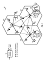
FIGURE 1 shows awireless communication network 100, which may be an LTE-A network, in which estimating interference using reference signal tones, data tones, and a traffic-to-power ratio may be implemented. Thewireless network 100 includes a number of evolved nodeBs (eNodeBs) 110 and other network entities. An eNodeB may be a station that communicates with the UEs and may also be referred to as a base station, a node B, an access point, and the like. EacheNodeB 110 may provide communication coverage for a particular geographic area. In 3GPP, the term "cell" can refer to this particular geographic coverage area of an eNodeB and/or an eNodeB subsystem serving the coverage area, depending on the context in which the term is used. - An eNodeB may provide communication coverage for a macro cell, a pico cell, a femto cell, and/or other types of cell. A macro cell generally covers a relatively large geographic area (e.g., several kilometers in radius) and may allow unrestricted access by UEs with service subscriptions with the network provider. A pico cell would generally cover a relatively smaller geographic area and may allow unrestricted access by UEs with service subscriptions with the network provider. A femto cell would also generally cover a relatively small geographic area (e.g., a home) and, in addition to unrestricted access, may also provide restricted access by UEs having an association with the femto cell (e.g., UEs in a closed subscriber group (CSG), UEs for users in the home, and the like). An eNodeB for a macro cell may be referred to as a macro eNodeB. An eNodeB for a pico cell may be referred to as a pico eNodeB. And, an eNodeB for a femto cell may be referred to as a femto eNodeB or a home eNodeB. In the example shown in
FIGURE 1 , theeNodeBs macro cells eNodeB 110x is a pico eNodeB for apico cell 102x. And, theeNodeBs femto cells - The
wireless network 100 may also include relay stations. A relay station is a station that receives a transmission of data and/or other information from an upstream station (e.g., an eNodeB, UE, etc.) and sends a transmission of the data and/or other information to a downstream station (e.g., a UE or an eNodeB). A relay station may also be a UE that relays transmissions for other UEs. In the example shown inFIGURE 1 , arelay station 110r may communicate with the eNodeB 110a and aUE 120r in order to facilitate communication between the eNodeB 110a and theUE 120r. A relay station may also be referred to as a relay eNodeB, a relay, etc. - The
wireless network 100 may be a heterogeneous network that includes eNodeBs of different types, e.g., macro eNodeBs, pico eNodeBs, femto eNodeBs, relays, etc. These different types of eNodeBs may have different transmit power levels, different coverage areas, and different impact on interference in thewireless network 100. For example, macro eNodeBs may have a high transmit power level (e.g., 20 Watts) whereas pico eNodeBs, femto eNodeBs and relays may have a lower transmit power level (e.g., 1 Watt). - The
wireless network 100 may support synchronous or asynchronous operation. For synchronous operation, the eNodeBs may have similar frame timing, and transmissions from different eNodeBs may be approximately aligned in time. For asynchronous operation, the eNodeBs may have different frame timing, and transmissions from different eNodeBs may not be aligned in time. The techniques described herein may be used for either synchronous or asynchronous operations. - In one aspect, the
wireless network 100 may support Frequency Division Duplex (FDD) or Time Division Duplex (TDD) modes of operation. The techniques described herein may be used for either FDD or TDD mode of operation. - A
network controller 130 may couple to a set ofeNodeBs 110 and provide coordination and control for theseeNodeBs 110. Thenetwork controller 130 may communicate with theeNodeBs 110 via a backhaul. TheeNodeBs 110 may also communicate with one another, e.g., directly or indirectly via a wireless backhaul or a wireline backhaul. - The
UEs 120 are dispersed throughout thewireless network 100, and each UE may be stationary or mobile. A UE may also be referred to as a terminal, a mobile station, a subscriber unit, a station, or the like. A UE may be a cellular phone, a personal digital assistant (PDA), a wireless modem, a wireless communication device, a handheld device, a laptop computer, a cordless phone, a wireless local loop (WLL) station, a tablet, or the like. A UE may be able to communicate with macro eNodeBs, pico eNodeBs, femto eNodeBs, relays, and the like. InFIGURE 1 , a solid line with double arrows indicates desired transmissions between a UE and a serving eNodeB, which is an eNodeB designated to serve the UE on the downlink and/or uplink. A dashed line with double arrows indicates interfering transmissions between a UE and an eNodeB. - LTE utilizes orthogonal frequency division multiplexing (OFDM) on the downlink and single-carrier frequency division multiplexing (SC-FDM) on the uplink. OFDM and SC-FDM partition the system bandwidth into multiple (K) orthogonal subcarriers, which are also commonly referred to as tones, bins, or the like. Each subcarrier may be modulated with data. In general, modulation symbols are sent in the frequency domain with OFDM and in the time domain with SC-FDM. The spacing between adjacent subcarriers may be fixed, and the total number of subcarriers (K) may be dependent on the system bandwidth.
-
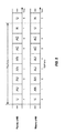
FIGURE 2 shows a downlink FDD frame structure used in LTE. The transmission timeline for the downlink may be partitioned into units of radio frames. Each radio frame may have a predetermined duration (e.g., 10 milliseconds (ms)) and may be partitioned into 10 subframes with indices of 0 through 9. Each subframe may include two slots. Each radio frame may thus include 20 slots with indices of 0 through 19. Each slot may include L symbol periods, e.g., 7 symbol periods for a normal cyclic prefix (as shown inFIGURE 2 ) or6 symbol periods for an extended cyclic prefix. The 2L symbol periods in each subframe may be assigned indices of 0 through 2L-1. The available time frequency resources may be partitioned into resource blocks. Each resource block may cover N subcarriers (e.g., 12 subcarriers) in one slot. - In LTE, an eNodeB may send a primary synchronization signal (PSC or PSS) and a secondary synchronization signal (SSC or SSS) for each cell in the eNodeB. For FDD mode of operation, the primary and secondary synchronization signals may be sent in
symbol periods subframes FIGURE 2 . The synchronization signals may be used by UEs for cell detection and acquisition. For FDD mode of operation, the eNodeB may send a Physical Broadcast Channel (PBCH) insymbol periods 0 to 3 inslot 1 ofsubframe 0. The PBCH may carry certain system information. - The eNodeB may send a Physical Control Format Indicator Channel (PCFICH) in the first symbol period of each subframe, as seen in
FIGURE 2 . The PCFICH may convey the number of symbol periods (M) used for control channels, where M may be equal to 1, 2 or 3 and may change from subframe to subframe. M may also be equal to 4 for a small system bandwidth, e.g., with less than 10 resource blocks. In the example shown inFIGURE 2 , M=3. The eNodeB may send a Physical HARQ Indicator Channel (PHICH) and a Physical Downlink Control Channel (PDCCH) in the first M symbol periods of each subframe. The PDCCH and PHICH are also included in the first three symbol periods in the example shown inFIGURE 2 . The PHICH may carry information to support hybrid automatic retransmission (HARQ). The PDCCH may carry information on uplink and downlink resource allocation for UEs and power control information for uplink channels. The eNodeB may send a Physical Downlink Shared Channel (PDSCH) in the remaining symbol periods of each subframe. The PDSCH may carry data for UEs scheduled for data transmission on the downlink. - The eNodeB may send the PSC, SSC and PBCH in the center 1.08 MHz of the system bandwidth used by the eNodeB. The eNodeB may send the PCFICH and PHICH across the entire system bandwidth in each symbol period in which these channels are sent. The eNodeB may send the PDCCH to groups of UEs in certain portions of the system bandwidth. The eNodeB may send the PDSCH to groups of UEs in specific portions of the system bandwidth. The eNodeB may send the PSC, SSC, PBCH, PCFICH and PHICH in a broadcast manner to all UEs, may send the PDCCH in a unicast manner to specific UEs, and may also send the PDSCH in a unicast manner to specific UEs.
- A number of resource elements may be available in each symbol period. Each resource element may cover one subcarrier in one symbol period and may be used to send one modulation symbol, which may be a real or complex value. For symbols that are used for control channels, the resource elements not used for a reference signal in each symbol period may be arranged into resource element groups (REGs). Each REG may include four resource elements in one symbol period.
- A UE may know the specific REGs used for the PHICH and the PCFICH. The UE may search different combinations of REGs for the PDCCH. The number of combinations to search is typically less than the number of allowed combinations for all UEs in the PDCCH. An eNodeB may send the PDCCH to the UE in any of the combinations that the UE will search.
- A UE may be within the coverage of multiple eNodeBs. One of these eNodeBs may be selected to serve the UE. The serving eNodeB may be selected based on various criteria such as received power, path loss, signal-to-noise ratio (SNR), etc.
-
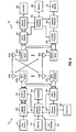
FIGURE 4 shows a block diagram of a design of a base station/eNodeB 110 and aUE 120, which may be one of the base stations/eNodeBs and one of the UEs inFIGURE 1 . Thebase station 110 may be themacro eNodeB 110c inFIGURE 1 , and theUE 120 may be theUE 120y. Thebase station 110 may also be a base station of some other type. Thebase station 110 may be equipped withantennas 434a through 434t, and theUE 120 may be equipped withantennas 452a through 452r. - At the
base station 110, a transmitprocessor 420 may receive data from adata source 412 and control information from a controller/processor 440. The control information may be for the PBCH, PCFICH, PHICH, PDCCH, etc. The data may be for the PDSCH, etc. Theprocessor 420 may process (e.g., encode and symbol map) the data and control information to obtain data symbols and control symbols, respectively. Theprocessor 420 may also generate reference symbols, e.g., for the PSS, SSS, and cell-specific reference signal. A transmit (TX) multiple-input multiple-output (MIMO)processor 430 may perform spatial processing (e.g., precoding) on the data symbols, the control symbols, and/or the reference symbols, if applicable, and may provide output symbol streams to the modulators (MODs) 432a through 432t. Each modulator 432 may process a respective output symbol stream (e.g., for OFDM, etc.) to obtain an output sample stream. Each modulator 432 may further process (e.g., convert to analog, amplify, filter, and upconvert) the output sample stream to obtain a downlink signal. Downlink signals frommodulators 432a through 432t may be transmitted via theantennas 434a through 434t, respectively. - At the
UE 120, theantennas 452a through 452r may receive the downlink signals from thebase station 110 and may provide received signals to the demodulators (DEMODs) 454a through 454r, respectively. Each demodulator 454 may condition (e.g., filter, amplify, downconvert, and digitize) a respective received signal to obtain input samples. Each demodulator 454 may further process the input samples (e.g., for OFDM, etc.) to obtain received symbols. AMIMO detector 456 may obtain received symbols from all thedemodulators 454a through 454r, perform MIMO detection on the received symbols if applicable, and provide detected symbols. A receiveprocessor 458 may process (e.g., demodulate, deinterleave, and decode) the detected symbols, provide decoded data for theUE 120 to adata sink 460, and provide decoded control information to a controller/processor 480. - On the uplink, at the
UE 120, a transmitprocessor 464 may receive and process data (e.g., for the PUSCH) from adata source 462 and control information (e.g., for the PUCCH) from the controller/processor 480. Theprocessor 464 may also generate reference symbols for a reference signal. The symbols from the transmitprocessor 464 may be precoded by aTX MIMO processor 466 if applicable, further processed by themodulators 454a through 454r (e.g., for SC-FDM, etc.), and transmitted to thebase station 110. At thebase station 110, the uplink signals from theUE 120 may be received by the antennas 434, processed by the demodulators 432, detected by aMIMO detector 436 if applicable, and further processed by a receiveprocessor 438 to obtain decoded data and control information sent by theUE 120. Theprocessor 438 may provide the decoded data to adata sink 439 and the decoded control information to the controller/processor 440. Thebase station 110 can send messages to other base stations, for example, over anX2 interface 441. - The controllers/
processors base station 110 and theUE 120, respectively. Theprocessor 440 and/or other processors and modules at thebase station 110 may perform or direct the execution of various processes for the techniques described herein. Theprocessor 480 and/or other processors and modules at theUE 120 may also perform or direct the execution of the functional blocks illustrated in useFIGURES 6A ,6B ,7 ,8 and10 , and/or other processes for the techniques described herein. Thememories base station 110 and theUE 120, respectively. Ascheduler 444 may schedule UEs for data transmission on the downlink and/or uplink. - Wireless networks may have eNBs of different power classes. For example, three power classes may be defined, in decreasing power class, as macro eNBs, pico eNBs, and femto eNBs. Networks featuring such different power class eNBs may be referred to as heterogeneous networks. When macro eNBs, pico eNBs, and femto eNBs are in a co-channel deployment, the power spectral density (PSD) of the macro eNB (aggressor eNB) may be larger than the PSD of the pico eNB and the femto eNB (victim eNBs) creating large amounts of interference with the pico eNB and the femto eNB. Protected subframes may be used to reduce or minimize interference with the pico eNBs and femto eNBs. That is, a protected subframe may be scheduled for the victim eNB to correspond with a prohibited subframe on the aggressor eNB.
- Referring back to
FIGURE 1 , theheterogeneous wireless network 100 uses the diverse set of eNBs 110 (i.e., macro eNBs, pico eNBs, femto eNBs, and relays) to improve the spectral efficiency of the system per unit area. Themacro eNBs 110a-c are usually carefully planned and placed by the provider of thewireless network 100. Themacro eNBs 110a-c generally transmit at high power levels (e.g., 5 W - 40 W). Thepico eNB 110x and therelay 110r, which generally transmit at substantially lower power levels (e.g., 100 mW - 2 W), may be deployed in a relatively unplanned manner to eliminate coverage holes in the coverage area provided by themacro eNBs 110a-c and improve capacity in the hot spots. The femto eNBs 110y-z, which are typically deployed independently from thewireless network 100 may, nonetheless, be incorporated into the coverage area of thewireless network 100 either as a potential access point to thewireless network 100, if authorized by their administrator(s), or at least as an active and aware eNB that may communicate with theother eNBs 110 of thewireless network 100 to perform resource coordination and coordination of interference management. The femto eNBs 110y-z typically also transmit at substantially lower power levels (e.g., 100 mW - 2 W) than themacro eNBs 110a-c. - In operation of a heterogeneous network, such as the
wireless network 100, each UE is usually served by theeNB 110 with the better signal quality, while the unwanted signals received from theother eNBs 110 are treated as interference. While such operational principals can lead to significantly sub-optimal performance, gains in network performance are realized in thewireless network 100 by using intelligent resource coordination among theeNBs 110, better server selection strategies, and more advanced techniques for efficient interference management. - A pico eNB, such as the
pico eNB 110x, is characterized by a substantially lower transmit power when compared with a macro eNB, such as themacro eNBs 110a-c. A pico eNB will also usually be placed around a network, such as thewireless network 100, in an ad hoc manner. Because of this unplanned deployment, wireless networks with pico eNB placements, such as thewireless network 100, can be expected to have large areas with low signal to interference conditions, which can make for a more challenging RF environment for control channel transmissions to UEs on the edge of a coverage area or cell (a "cell-edge" UE). Moreover, the potentially large disparity (e.g., approximately 20 dB) between the transmit power levels of themacro eNBs 110a-c and thepico eNB 110x implies that, in a mixed deployment, the downlink coverage area of thepico eNB 110x will be much smaller than that of themacro eNBs 110a-c. - In the uplink case, however, the signal strength of the uplink signal is governed by the UE, and, thus, will be similar when received by any type of the
eNBs 110. With the uplink coverage areas for theeNBs 110 being roughly the same or similar, uplink handoff boundaries will be determined based on channel gains. This can lead to a mismatch between downlink handover boundaries and uplink handover boundaries. Without additional network accommodations, the mismatch would make the server selection or the association of UE to eNB more difficult in thewireless network 100 than in a macro eNB-only homogeneous network, where the downlink and uplink handover boundaries are more closely matched. - If server selection is based predominantly on downlink received signal strength, as provided in the
LTE Release 8 standard, the usefulness of mixed eNB deployment of heterogeneous networks, such as thewireless network 100, will be greatly diminished. This is because the larger coverage area of the higher powered macro eNBs, such as themacro eNBs 110a-c, limits the benefits of splitting the cell coverage with the pico eNBs, such as thepico eNB 110x, because, the higher downlink received signal strength of themacro eNBs 110a-c will attract all of the available UEs, while thepico eNB 110x may not be serving any UE because of its much weaker downlink transmission power. Moreover, themacro eNBs 110a-c will likely not have sufficient resources to efficiently serve those UEs. Therefore, thewireless network 100 will attempt to actively balance the load between themacro eNBs 110a-c and thepico eNB 110x by expanding the coverage area of thepico eNB 110x. This concept is referred to as range extension. - The
wireless network 100 achieves this range extension by changing the manner in which server selection is determined. Instead of basing server selection on downlink received signal strength, selection is based more on the quality of the downlink signal. In one such quality-based determination, server selection may be based on determining the eNB that offers the minimum path loss to the UE. Additionally, the wireless network provides a fixed partitioning of resources equally between themacro eNBs 110a-c and thepico eNB 110x. However, even with this active balancing of load, downlink interference from themacro eNBs 110a-c should be mitigated for the UEs served by the pico eNBs, such as thepico eNB 110x. This can be accomplished by various methods, including interference cancellation at the UE, resource coordination among theeNBs 110, or the like. - In a heterogeneous network with range extension, such as the
wireless network 100, in order for UEs to obtain service from the lower-powered eNBs, such as thepico eNB 110x, in the presence of the stronger downlink signals transmitted from the higher-powered eNBs, such as themacro eNBs 110a-c, thepico eNB 110x engages in control channel and data channel interference coordination with the dominant interfering ones of themacro eNBs 110a-c. Many different techniques for interference coordination may be employed to manage interference. For example, inter-cell interference coordination (ICIC) may be used to reduce interference from cells in co-channel deployment. One ICIC mechanism is adaptive resource partitioning. Adaptive resource partitioning assigns subframes to certain eNBs. In subframes assigned to a first eNB, neighbor eNBs do not transmit. Thus, interference experienced by a UE served by the first eNB is reduced. Subframe assignment may be performed on both the uplink and downlink channels. - For example, subframes may be allocated between three classes of subframes: protected subframes (U subframes), prohibited subframes (N subframes), and common subframes (C subframes). Protected subframes are assigned to a first eNB for use exclusively by the first eNB. Protected subframes may also be referred to as "clean" subframes based on the lack of interference from neighboring eNBs. Prohibited subframes are subframes assigned to a neighbor eNB, and the first eNB is prohibited from transmitting data during the prohibited subframes. For example, a prohibited subframe of the first eNB may correspond to a protected subframe of a second interfering eNB. Thus, the first eNB is the only eNB transmitting data during the first eNB's protected subframe. Common subframes may be used for data transmission by multiple eNBs. Common subframes may also be referred to as "unclean" subframes because of the possibility of interference from other eNBs.
- At least one protected subframe is statically assigned per period. In some cases only one protected subframe is statically assigned. For example, if a period is 8 milliseconds, one protected subframe may be statically assigned to an eNB during every 8 milliseconds. Other subframes may be dynamically allocated.
- Resource partitioning information allows the non-statically assigned subframes to be dynamically allocated. Any of protected, prohibited, or common subframes may be dynamically allocated (AU, AN, AC subframes, respectively). The dynamic assignments may change quickly, such as, for example, every one hundred milliseconds or less.
-
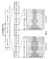
FIGURE 5 is a block diagram illustrating TDM partitioning, a type of resource partitioning, in a heterogeneous network according to one aspect of the disclosure. A first row of blocks illustrate sub frame assignments for a femto eNodeB, and a second row of blocks illustrate sub frame assignments for a macro eNodeB. Each of the eNodeBs has a static protected sub frame during which the other eNodeB has a static prohibited sub frame. For example, the femto eNodeB has a protected sub frame (U sub frame) insub frame 0 corresponding to a prohibited sub frame (N sub frame) insub frame 0. Likewise, the macro eNodeB has a protected sub frame (U sub frame) insub frame 7 corresponding to a prohibited sub frame (N sub frame) insub frame 7. Sub frames 1-6 are dynamically assigned as either protected sub frames (AU), prohibited sub frames (AN), and common sub frames (AC). The dynamically assigned subframes (AU/AN/AC) are referred to herein collectively as 'X' subframes. During the dynamically assigned common sub frames (AC) insub frames - Protected sub frames (such as U/AU sub frames) have reduced interference and a high channel quality because aggressor eNodeBs are prohibited from transmitting. Prohibited sub frames (such as N/AN sub frames) have no data transmission to allow victim eNodeBs to transmit data with low interference levels. Common sub frames (such as C/AC sub frames) have a channel quality dependent on the number of neighbor eNodeBs transmitting data. For example, if neighbor eNodeBs are transmitting data on the common sub frames, the channel quality of the common sub frames may be lower than the protected sub frames. Channel quality on common sub frames may also be lower for cell range extension (CRE) area (also referred to as extended boundary area (EBA)) UEs strongly affected by aggressor eNodeBs. A CRE area UE may belong to a first eNodeB but also be located in the coverage area of a second eNodeB. For example, a UE communicating with a macro eNodeB that is near the range limit of a femto eNodeB coverage is an CRE area UE.
- In order for a UE to demodulate and decode received data, it may perform interference estimation to determine the reliability of desired symbols received from the serving cell. In particular, when a UE is in a location where it receives a signal from multiple cells, the ability for the UE to accurately estimate interference is desirable. As illustrated in
FIGURE 1 , a UE such as theUE 120x may desire to receive a signal from theeNB 110b and may perform interference analysis to estimate interference caused by thepico cell 110x. One method of interference analysis is for the UE to estimate interference based on reference signal tones, such as common reference signal tones, to account for interference caused by neighboring cells. Broadcast common reference signal tones may be measured and used to estimate interference on a channel so that the interference on the channel can be cancelled. Common reference signal interference cancellation may be used for decoding downlink control and data channels (e.g., PDCCH/PDSCH). This enables more accurate Radio Resource Management measurements. - Common reference signal interference cancellation may sometimes provide inaccurate interference estimates because interfering cells transmit common reference signal pilot tones whether or not the cells are transmitting data. The interference estimates are generally based on interference detected on the common reference signal pilot tones. However, in some situations, the interference estimates based on pilot tones could be quite different from interference that is actually present. For example, a UE that detects the pilot tone may estimate interference based upon an assumption that the interferer is transmitting data even when no data tones are actually being transmitted from the interferer. This incorrect assumption may cause the UE to overestimate the interference and have a negative impact on link performance.
- Partial loading and/or resource partitioning in a heterogeneous network may also create mismatches between interference estimates based on a common reference signal pilot tones of an interfering signal and actual interference from data transmissions of the interferer. For example, a mismatch can occur if a cell ID combination of the serving cell and interfering cell result in a collision between common reference signal tones of the interferer and common reference signal tones of the serving cell, in situations when the UE has no information on whether the interferer is transmitting data, particularly with regard to the 'X' subframes discussed with respect to
FIGURE 5 . In such situations, the interference estimate based on common reference signal tones may be different from the actual interference seen on data tones because the estimate would be accounting for interference which did not exist on data tones. This mismatch may impact link performance. - Differences between estimated interference and actual interference could have a large impact on communication link performance. Link performance conditions, such as throughput and frame error rate, for example, may be improved if the interference condition on data tones is known to the UE.
- One approach to informing a UE of interference conditions on data tones involves signalling of neighbor cell loading status. However, even with such additional signalling, this approach may not provide enough information to a UE when the interferer is partially loaded.
- Another solution to this mismatch is to use UE-specific reference signals (UE-RSs) for interference estimation. This solution, however, is limited to certain unicast data channels, such as physical downlink shared channels (PDSCHs) that contain UE-RSs. The solution is not appropriate with data channels that do not contain UE-RSs, nor with the Physical Control Format Indicator Channel (PCFICH), Physical HARQ Indicator Channel (PHICH), or Physical Downlink Control Channel (PDCCH).
- An interference estimate based on reference signal tones, such as common reference signal (CRS) tones, offers good performance across a wide range of signal to noise ratios (SNRs), particularly in a full loading scenario (where all nearby cells are actively transmitting data). The interference estimate, however, may suffer from mismatch problems described above. An interference estimate based on data tones avoids the mismatch problem but may suffer from poor estimation accuracy at high SNRs.
-
FIGURE 6A illustrates interference estimation according to aspects of the present disclosure. First, a UE determines which interference estimation to use based on a reliability determination, shown inblock 602. If interference estimation based on a reference signal is determined to be reliable, as shown inblock 606, it is used. If interference estimation based on data tones is determined to be reliable, as shown inblock 604, a method is chosen to calculate the data tones interference estimate. The data tones interference estimate may be calculated from a traffic-to-pilot ratio, as shown inblock 608. The TPR estimate may optionally be improved inblock 609, as described in more detail below. The data tones interference estimate may be calculated from the covariance matrices, as discussed above and shown inblock 610. As the covariance solution is more complex, when overall processing resources are a limiting factor, the TRP solution should be selected. The data tones interference estimate may also be calculated using other methods. - In one aspect of the present disclosure, reliability of the interference estimate is decided, as seen in
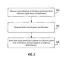
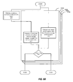
FIGURE 3 . In this aspect, a UE measures received power of colliding interferers from the reference signal tones of the interferer atblock 302. The UE may also measure the total received power on the data tones [as explained in more detail below] atblock 304. Based on these power measurements the UE decides whether a data tone based interference estimate will be reliable atblock 306. If the UE selects the data tones approach, then the UE can determine reliability as described below. If the UE uses the TPR approach to estimate interference, the UE observes whether the dominant colliding interferer is some amount (e.g., 10dB) weaker than the serving cell. If so, then the data tone based interference is not reliable. Of course other rules can be employed to determine reliability, and these examples are non-limiting. - One aspect for performing the hybrid interference estimation is described below with reference to
FIGURE 6B . First, an interference estimate is performed based on CRS tones at block 620. Second, at block 622 a covariance matrix Rhh is calculated according to the following formula:
where the expected value function (e.g., averaging) E is over a set of resource elements (REs) for which one interference estimate is calculated, - TPR is the traffic-to-pilot power ratio scalar representing how much data is boosted over the pilot,
- h is the serving cell channel estimate, and
- H represents a Hermitian conjugate transposition operation, a known mathematical function for matrices.
- Rhh may be calculated in parallel with the interference estimate based on CRS tones.
- At
block 624, a covariance matrix of the received signal Ryy is also calculated according to the following formula:
where the expected value function (e.g., averaging) E is over the same set of resource elements used above for Rhh for which one interference estimate is calculated, - y is the received signal, and
- H represents a Hermitian conjugate transposition operation.
- Ryy may be calculated in parallel with the interference estimate based on CRS tones and / or in parallel with Rhh.
- A data tones interference estimate may then be defined by comparing Ryy and Rhh. In one aspect the following formula is used:

where NT_data is the data tones interference estimate. Thus, if the value of a received signal minus the expected value is large, a significant amount of noise is indicated. If the value is smaller, a lower amount of noise is indicated. - At
block 626 it is determined whether If Ryy is substantially larger than Rhh. If so, then a low signal-to-noise ratio (SNR) is implied, indicating an increased amount of noise as well as a reliable interference estimation based on data tones. If Ryy is comparable to Rhh, then a high SNR is implied, indicating a lower amount of noise as well as an unreliable interference estimation based on data tones. If the interference estimation based on data tones (Nt_data) is deemed reliable, it is used (block 604FIGURE 6A ). If the interference estimation based on data tones is deemed unreliable then the interference estimation based on reference signals is used (block 606FIGURE 6A ). - As Ryy and Rhh are both matrices, various methods may be used to determine the ordering of the matrices. In one further aspect, Ryy may be compared with Rhh using mathematical trace operations, i.e., tr(Ryy) and tr(Rhh), which compares the sum of the diagonal terms of the respective matrices. In this aspect, the reliability of the data tones interference estimate is based on whether tr(Ryy) - tr(Rhh) is greater than a certain threshold. Therefore, if tr(Ryy) - tr(Rhh) is greater than a certain threshold, the data tones interference estimate Nt_data = Ryy - Rhh is used.
- A data tones interference estimate Nt_data may be for a
specific channel - According to an aspect of the present disclosure, a single data tones interference estimate Nt_data is calculated for an entire control region. The control region refers to the first few orthogonal frequency division multiplexing (OFDM) symbols allocated for PCFICH, PHICH, and PDCCH transmission in each subframe. In another aspect, a data tones interference estimate is calculated for a unit in a data region. The data region refers to the rest of the OFDM symbols allocated for PDSCH transmission in each subframe. The unit may be a resource block, multiple resource blocks, or the entire PDSCH region. In one aspect a data tones interference estimate is calculated for particular resource blocks. In this aspect, a decision between common reference signal tones interference estimation and data tones interference estimation is based on the reliability of the estimates on a resource block-by-resource block basis. In other words, a CRS tones estimate and a data tones estimate are compared for each resource block.
- According to an aspect of the present disclosure, a single, separate data tones interference estimate is calculated for the resource elements occupied by the PSS, SSS, and PBCH of neighboring cells. For normal cyclic prefix (CP), these resource elements correspond to the first four OFDM symbols in the second slot of each radio frame in time, and the center six resource blocks in frequency. According to another aspect of the present disclosure, a data tones interference estimate Nt_data is calculated based on a traffic-to-pilot ratio (TPR) estimated over the data tones.
- Calculating a data tones interference estimate based on a traffic-to-pilot ratio (TPR) estimated over the data tones is described with reference to
FIGURE 7 . A UE may estimate the interference by taking into account the fact that certain interferers are not transmitting data. According to this aspect, a UE may attempt to determine whether interferers with detected pilot tones are presently transmitting data. For this determination, the UE compares the total power on the data tones with the power the UE sees on the pilot tones from the interferers. This aspect includes determining a set of dominant interferers with pilot tones colliding with pilot tones of the serving cell inblock 702 and obtaining channel estimates of these dominant interferers and the serving cell inblock 704. - In
block 706, the presence or absence of data transmission from interferers is detected using the total received power on data tones and the norm of the channel estimates of the serving cell and dominant interferers. Alternatively, the UE may use the received power on candidate demodulation resource symbol (DM-RS)/UE-RS sequences of dominant interferers to detect the presence or absence of data transmissions from interferers. More generally the traffic-to-pilot ratio (TPR) of the interferers is estimated. - The TPR represents a ratio of powers at which the transmitted data (traffic) is divided by the power at which the pilot tones are transmitted. For example, a TPR of 0 indicates a pilot tone with no corresponding data transmission. A TPR of 1 indicates data is transmitted with the same power as the pilot tone. A TPR, which is a scalar quantity, may be estimated for individual interferers or collectively for a set of interferers.
- In
block 708, the covariance of the residual interference seen on the pilot tones is estimated. This estimate of the residual interference seen on pilot tones excludes the interference from the dominant colliding interferers having channels that were already estimated. Inblock 710, the overall interference covariance matrix is estimated as a function of the residual interference, the (scalar) TPR estimates of interferers, and covariance of the channel estimates of the dominant interferers. Here, the overall interference matrix is the sum of two parts. The first part represents the residual interference. The second part represents a scaled version of the covariance of the channel estimate of the dominant interferers. The scaling is determined by the TPR estimate of the interferer. - The methods to estimate interference according to aspects of the present disclosure provide several advantages over current techniques. For example, aspects of the present disclosure correctly estimate interference in partial loading scenarios in which an interferer does not send data on all resource blocks in a subframe. In such situations the UE may perform a resource block-by-resource block estimate to generate a more accurate estimate, for example. Aspects of the present disclosure may also correctly estimate interference in a heterogeneous network scenario on 'X' subframes. Also, in situations such as a heterogeneous network when a UE may not be aware of whether an interferer is sending data, the UE may detect the presence of an interferer and may still be able to generate a correct interference estimate.
- An alternative method of detecting the presence or absence of data transmissions from interferers (block 706,
FIGURE 7 ) using DM-RS transmissions of dominant interferers is described in more detail with reference toFIGURE 8 . According to standards, DM-RS has a fixed location and its scrambling code is a function of a cell ID and a scrambling code identifier. A demodulation resource symbol (DM-RS) is utilized to determine whether there is data transmission from an interfering cell - A DM-RS is transmitted by an interferer only if the interferer is sending data. Further, a candidate set of DM-RS sequences is known to the UE because the set of DM-RS sequences that may be transmitted by the interferer is a function of the cell ID of the interferer. Therefore, in
block 802, a UE may follow multiple hypotheses as to whether a particular interferer is presently transmitting data and whether the interferer is using a particular DM-RS sequence. Inblock 804, if the UE detects a large amount of energy on any of the DM-RS sequences that fits its hypothesis, then the UE can assume the DM-RS sequences belong to a particular interferer presently transmitting data inblock 806. - Detection of a DM-RS sequence of an interferer confirms that there is data transmission on the interferer. However, an interferer may still be transmitting data without utilizing a DM-RS sequence. Therefore, a lack of detected DM-RS sequence does not confirm the interferer is silent. According to aspects of the present disclosure, if a DM-RS sequence is not detected, then the UE may detect the interferer with common reference signal transmissions of the interferer and estimate the TPR of the interferer in
block 808. Interferers with a TPR estimated via DM-RS, need not be considered for TPR estimation via common reference signals. TPR estimates based upon DM-RS may improve TPR estimates based upon common reference signal transmissions of interferers. - Aspects of the present disclosure provide numerous techniques for estimating a TPR when the TPR of multiple interferers are to be estimated using total received power on data tones and the power of common reference signal transmissions of the interferers. According to one aspect of the present disclosure, a single TPR value which applies for all the interferers may be estimated. This technique may be suboptimal in some circumstances but works well in other circumstances, such as when a single interferer dominates.
- According to another aspect of the present disclosure, interferers may be partitioned such that interferers with similar spatial interference structure are in the same partition. In this case, a single TPR for each partition may be estimated. According to another aspect of the present disclosure, iterative approaches may be also be used. For example, initially it may be assumed that all interferers have an initial TPR estimate of 1 (or 0, or a fraction between 0 and 1). Then, the TPR of one interferer may be iteratively estimated assuming the other TPRs are exactly known. In other words, when multiple interferers are presently transmitting data, a UE may first assume that the weaker interferers are present. The UE may then only try to estimate the TPR of the stronger interferers. Based on the estimate of the stronger interferers, the UE may decide to perform further iterations to estimate the TPR of progressively weaker interferers, and thereby test the initial assumption that particular weaker interferers are present.
- Certain aspects of the disclosure may provide improved granularity of the TPR estimate, i.e., the number of TPR estimates computed on a given subframe. In one example, one TPR estimate may be computed for each resource block (RB), the minimum unit of resource allocation to a UE. In one aspect, the granularity may be varied so that one TPR estimate can be computed over multiple resource blocks. This may be beneficial if it is known that interference does not vary too much across resource blocks, for example. In another example, two TPR estimates may be computed for each resource block. In still another example, one single TPR estimate may be computed for the two resource blocks in a subframe. This may be beneficial for subframes carrying relay backhaul traffic from a donor eNB, as the first and second slots within the same subframe can have different characteristics. Similarly, within a resource block, a different TPR estimate may be generated for every tone or set of tones (e.g., resource element group (REG)), for example.
- According to another aspect of the present disclosure, the quality of the TPR estimate may be further improved by quantization (609
FIGURE 6 ). It is generally known with a high probability that a TPR estimate should fall within a certain range. For example, the TPR is known to be a non-negative real number which is generally between the values of 0.5 and 2 (i.e., -6dB to 3dB). - According to an aspect of the present disclosure, a quantization rule is designed to leverage the above observations. Because of the known range, quantization rules may be implemented to change TPR estimates that fall outside of a predetermined range. For example, if a TPR estimate is less than 0.1, it can be quantized to a value of zero. Similarly, if the TPR estimate is high and outside of a normal range, then it could be quantized to a more nominal value.
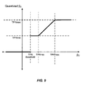
- A method of quantizing a TPR estimate according to an illustrative aspect of the present disclosure is described with reference to
FIGURE 9 . A range of estimated TPR values which may be input to the quantization process is shown on the horizontal axis labeled 'β2'. A range of quantized TPR values that result from the quantization process are shown on the vertical axis labeled 'Quantized β2'. Three predetermined parameters, TPRmax, TPRmin and TPR threshold are also used in the quantization process. - According to the illustrated quantization process, if the estimated TPR (β2) is less than TPR threshold then the quantized estimate (Quantized β2) is set to zero. If the estimated TPR (β2) is greater than TPRmax then the quantized estimate (Quantized β2) is set to TPRmax. If the estimated TPR (β2) exceeds TPR threshold but is less than TPRmin, then the quantized estimate (Quantized β2) is set to TPRmin. If none of these conditions are satisfied by the estimated TPR (β2), then the estimated TPR (β2) is left unchanged and the quantized estimate (Quantized β2) equals the estimated TPR (β2).
- In one aspect of the present disclosure, the three predetermined parameters TPRmin, TPRmax and TPR threshold in the quantization process may be set as follows: If an interferer TPR is known then TPRmin and TPRmax are set to this known value of the interferer TPR. In this case TPR threshold may be set to 0.3 times the known interferer TPR. In an alternative aspect, these parameters may be further improved by setting them, for example, as a function of the pre-interference cancellation (IC) signal to noise ratio (SNR) of the serving cell and dominant interferer. If the serving cell TPR is unknown, then TPRmin may be set to -9dB, TPRmax may be set to 6dB and TPR threshold may be set to -9dB. Of course, such values are merely exemplary and may be configured differently, when appropriate.
- According to another aspect of the present disclosure, a TPR estimate may be changed to a default value of 1 if the dominant interferer is very weak compared to the serving cell. In this case, the TPR estimate is known to be unreliable so a default value of 1 can be assigned. That is, if a UE determines that a TPR estimate is not reliable because the dominant interferer is very weak, the UE nonetheless assumes that the interferer is present. This aspect of the disclosure is compatible with the behavior of existing UEs which assume that an interferer is present whenever the UEs detect the interferer's pilot tone.
- According to the aspects of the present disclosure, a threshold for deciding to use the default TPR value of 1 may be based on pre-interference cancellation (pre-IC) reference signal (RS) power estimates of the serving cell and the interferer. In one example, the default TPR is used when the interferer power estimate is less than the pre-IC RS power estimate of the serving cell. In another example, the ratio of the RS power of the strongest interferer to the serving cell is computed and the default TPR estimate of 1 is forced if the computed ratio falls below a certain threshold.
- In another example, the threshold for deciding to use the default TPR value of 1 may be based on quantities that are function of the post-IC reference signal channel estimates, such as wideband reference signal received power estimates. In yet another example, power estimates of more than one interferer may be used to decide whether to use the default TPR value.
- Another aspect of the present disclosure provides an improved TPR estimate of an interferer by soft cancelling serving cell data (609
FIGURE 6 ). The present disclosure includes two schemes, a symbol level scheme and a codeword level scheme, to cancel out data from a serving cell and thereby obtain a more reliable estimate of the interferer. One method of estimating an interference level is to use an equation such as: - 1.

- 2. where y = signal received from the channel
- 3. hs = serving cell signal
- 4. xs = serving cell data
- 5. hi = interfering cell signal
- 6. xi = interfering cell data
- 7. n = noise
- 8. β = the estimated quantity of interference.
- The above equation allows an estimate of whether β is 0 (indicating no interference present) or 1 (indicating interference is present). After determining a value of y, an estimate ĥsx̂s of the serving cell may be approximate to the received channel y. That serving cell estimate may be subtracted from ŷ, an estimate of the received channel, to arrive at β ĥix̂i, which is β times the estimate of the interfering cell received signal:
- 9.

- 10. The above equation may assist in estimating β.
- The above equations may be solved on a symbol level where the calculations and estimates are on a symbol-by-symbol basis (e.g., where xs is a vector for each symbol (of n symbols) of x = xs1, xs2..... xsn) or the equations may be solved on a codeword level, where the values represent received codewords, thus improving decoding speed.
- According to the symbol level scheme, an estimate of the serving cell data is obtained by signal constellation demapping. This estimate is then subtracted out from the received data tones leading to a more accurate estimate of the interferer TPRs. If the serving cell is very strong as compared to the interferer, and if the precoding matrix used for data transmission is known, then it is possible to estimate the modulation order (i.e., 2 for QPSK, 4 for 16-QAM and 6 for 64-QAM) and also the modulation symbol used with a high degree of reliability on a per tone basis.
- Soft symbol estimates that represent a weighted average of all modulation symbols in the modulation scheme may also be used in the symbol level scheme. The weights depend on the likelihood of the symbol being transmitted in a particular received signal vector.
- In codeword level schemes, soft estimates of the modulation symbol used by a serving cell can be obtained from log likelihood ratios (LLRs) of the turbo decoder on a per RE (resource element) basis. Here, the UE lets the decoder run a given noise estimate. The decoder may indicate with a good probability whether certain bits are zero or one. The decoder may also indicate the symbols to which these bits are mapped. According to this codeword level scheme, the soft estimates are subtracted out and a TPR estimate of the interferer can be computed.
- Iterations between TPR estimates and soft symbol estimates may further improve performance because better TPR estimates improve the interference estimates. This, in turn, helps turbo decoding and results in a better soft symbol estimate which when subtracted leads to a better TPR estimate of the interferer.
-
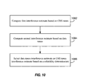
FIGURE 10 is a flow diagram illustrating interference estimation in a user equipment according to one aspect of the present disclosure. An apparatus, such as aUE 120 is configured to compute an interference estimate based on reference signal tones, such as common reference signal (CRS) tones, as shown inblock 1002. The UE is also configured to compute an interference estimate based on data tones as shown inblock 1004. The controller/processor 480, thememory 482, the receiveprocessor 458, thedemodulators 454a, and/or theantennas 452a may be configured to perform the computing. - The UE is further configured to select the data tones interference estimate or reference signal tones interference estimate based on a reliability determination as shown in
block 1006. The controller/processor 480, thememory 482, the receiveprocessor 458, thedemodulators 454a, and/or theantennas 452a may be configured to perform the selecting. - In one configuration, the
UE 120 configured for wireless communication includes means for selecting an interference estimate. The means may include means for computing a first interference estimate based on common reference signal tones, means for computing a second interference estimate based on data tones, and means for selecting either the data tones interference estimate or the common reference signal tones interference estimate based on a reliability determination. In one aspect, the aforementioned means may be the controller/processor 480, thememory 482, the receiveprocessor 458, thedemodulators 454a, and theantennas 452a configured to perform the functions recited by the aforementioned means. In another aspect, the aforementioned means may be a module or any apparatus configured to perform the functions recited by the aforementioned means. - Those of skill would further appreciate that the various illustrative logical blocks, modules, circuits, and algorithm steps described in connection with the disclosure herein may be implemented as electronic hardware, computer software, or combinations of both. To clearly illustrate this interchangeability of hardware and software, various illustrative components, blocks, modules, circuits, and steps have been described above generally in terms of their functionality. Whether such functionality is implemented as hardware or software depends upon the particular application and design constraints imposed on the overall system. Skilled artisans may implement the described functionality in varying ways for each particular application, but such implementation decisions should not be interpreted as causing a departure from the scope of the present disclosure.
- The various illustrative logical blocks, modules, and circuits described in connection with the disclosure herein may be implemented or performed with a general-purpose processor, a digital signal processor (DSP), an application specific integrated circuit (ASIC), a field programmable gate array (FPGA) or other programmable logic device, discrete gate or transistor logic, discrete hardware components, or any combination thereof designed to perform the functions described herein. A general-purpose processor may be a microprocessor, but in the alternative, the processor may be any conventional processor, controller, microcontroller, or state machine. A processor may also be implemented as a combination of computing devices, e.g., a combination of a DSP and a microprocessor, a plurality of microprocessors, one or more microprocessors in conjunction with a DSP core, or any other such configuration.
- The steps of a method or algorithm described in connection with the disclosure herein may be embodied directly in hardware, in a software module executed by a processor, or in a combination of the two. A software module may reside in RAM memory, flash memory, ROM memory, EPROM memory, EEPROM memory, registers, hard disk, a removable disk, a CD-ROM, or any other form of storage medium known in the art. An exemplary storage medium is coupled to the processor such that the processor can read information from, and write information to, the storage medium. In the alternative, the storage medium may be integral to the processor. The processor and the storage medium may reside in an ASIC. The ASIC may reside in a user terminal. In the alternative, the processor and the storage medium may reside as discrete components in a user terminal.
- In one or more exemplary designs, the functions described may be implemented in hardware, software, firmware, or any combination thereof. If implemented in software, the functions may be stored on or transmitted over as one or more instructions or code on a computer-readable medium. Computer-readable media includes both computer storage media and communication media including any medium that facilitates transfer of a computer program from one place to another. A storage media may be any available media that can be accessed by a general purpose or special purpose computer. By way of example, and not limitation, such computer-readable media can comprise RAM, ROM, EEPROM, CD-ROM or other optical disk storage, magnetic disk storage or other magnetic storage devices, or any other medium that can be used to carry or store desired program code means in the form of instructions or data structures and that can be accessed by a general-purpose or special-purpose computer, or a general-purpose or special-purpose processor. Also, any connection is properly termed a computer-readable medium. For example, if the software is transmitted from a website, server, or other remote source using a coaxial cable, fiber optic cable, twisted pair, digital subscriber line (DSL), or wireless technologies such as infrared, radio, and microwave, then the coaxial cable, fiber optic cable, twisted pair, DSL, or wireless technologies such as infrared, radio, and microwave are included in the definition of medium. Disk and disc, as used herein, includes compact disc (CD), laser disc, optical disc, digital versatile disc (DVD), floppy disk and blu-ray disc where disks usually reproduce data magnetically, while discs reproduce data optically with lasers. Combinations of the above should also be included within the scope of computer-readable media.
- The previous description of the disclosure is provided to enable any person skilled in the art to make or use the disclosure. Various modifications to the disclosure will be readily apparent to those skilled in the art, and the generic principles defined herein may be applied to other variations without departing from the scope of the disclosure. Thus, the disclosure is not intended to be limited to the examples and designs described herein but is to be accorded the widest scope consistent with the appended claims.
Claims (16)
- A method of wireless communication in an OFDMA wireless network (100), the method comprising::computing (1002) a first interference estimate based on reference signal tones;computing (1004) a second interference estimate based on data tones by estimating a traffic-to-pilot power ratio over data tones of colliding interferers and computing the second interference estimate based on the traffic-to-pilot power ratio; andselecting (1006) one of the data tones interference estimate and the reference signal tones interference estimate based on a reliability determination of the first interference estimate and the second interference estimate.
- The method of claim 1 in which computing the second interference estimate, comprises
calculating a covariance matrix of a received signal;
calculating a covariance matrix of a serving cell channel; and
deriving the second interference estimate using the two covariance matrices. - The method of claim 1 in which the reliability determination is based on comparing a covariance matrix of a received signal and a covariance matrix of a serving cell channel.
- The method of claim 3, in which the comparing is based on a scalar function of entries of the matrices.
- The method of claim 1 in which the data tones comprise at least one of tones from a physical downlink shared channel, a physical hybrid automatic repeat request indicator channel, a physical control format indicator channel, and a physical downlink control channel.
- The method of claim 1 in which computing the second interference estimate, comprises estimating interference for at least one of a control region and a resource block in a data region.
- The method of claim 1, in which computing the second interference estimate is based on the traffic-to-pilot power ratio, channel estimates of at least one dominant interferer, and residual interference.
- The method of claim 7, in which the residual interference comprises thermal noise and interference from other interferers excluding the at least one dominant interferer.
- The method of claim 1, further comprising partitioning colliding interferers based on spatial signature, the estimating comprising estimating a single traffic-to-pilot power ratio for each partition.
- The method of claim 1, in which estimating the traffic-to-pilot power ratio further comprises:obtaining a channel estimate of each dominant colliding interferer and a channel estimate of a serving cell;determining a norm of the channel estimates of each dominant interferer and the serving cell;determining total received power on data tones of the serving cell and data tones of the dominant interferers; anddividing the total received power of the data tones of the serving cell and data tones of the dominant interferers by the norm of channel estimates.
- The method of claim 1, in which estimating the traffic-to-pilot power ratio further comprises:determining received power of candidate de-modulation reference symbol (DM-RS) sequences of dominant interferers; andidentifying an interferer in response to detection of a de-modulation reference symbol of the interferer based on a comparison with received power of the reference signal tones of the same interferer.
- The method of claim 1, further comprising:quantizing the traffic-to-pilot power ratio estimate according to predetermined parameters.
- The method of claim 1, further comprising:forcing the traffic-to-pilot power ratio estimate to a default value in response to detecting an interferer power level below a predetermined threshold.
- The method of claim 1, further comprising:performing a soft cancellation of data transmitted by a serving cell at a symbol level or at a codeword level; andestimating the traffic-to-pilot power ratio of colliding interferers after cancellation of the data transmitted by the serving cell.
- An apparatus for wireless communication in an OFDMA network (100), comprising:means for computing (1002) a first interference estimate based on reference signal tones;means for computing (1004) a second interference estimate based on data tones by estimating a traffic-to-pilot power ratio over data tones of colliding interferers and computing the second interference estimate based on the traffic-to-pilot power ratio; andmeans for selecting (1006) one of the data tones interference estimate and the reference signal tones interference estimate based on a reliability determination of the first interference estimate and the second interference estimate.
- A computer program product for wireless communications in an OFDMA network, the computer program product comprising:a non-transitory computer-readable medium having program code recorded thereon to perform any one of the methods of claims 1 to 14.
Applications Claiming Priority (4)
| Application Number | Priority Date | Filing Date | Title |
|---|---|---|---|
| US37040010P | 2010-08-03 | 2010-08-03 | |
| US201161480288P | 2011-04-28 | 2011-04-28 | |
| US13/196,711 US9136953B2 (en) | 2010-08-03 | 2011-08-02 | Interference estimation for wireless communication |
| PCT/US2011/046391 WO2012018894A1 (en) | 2010-08-03 | 2011-08-03 | Improved interference estimation for wireless communication |
Publications (2)
| Publication Number | Publication Date |
|---|---|
| EP2601751A1 EP2601751A1 (en) | 2013-06-12 |
| EP2601751B1 true EP2601751B1 (en) | 2014-11-12 |
Family
ID=45559806
Family Applications (1)
| Application Number | Title | Priority Date | Filing Date |
|---|---|---|---|
| EP11749623.2A Active EP2601751B1 (en) | 2010-08-03 | 2011-08-03 | Improved interference estimation for wireless communication |
Country Status (6)
| Country | Link |
|---|---|
| US (1) | US9136953B2 (en) |
| EP (1) | EP2601751B1 (en) |
| JP (1) | JP5675981B2 (en) |
| KR (1) | KR101488735B1 (en) |
| CN (1) | CN103069730B (en) |
| WO (1) | WO2012018894A1 (en) |
Families Citing this family (47)
| Publication number | Priority date | Publication date | Assignee | Title |
|---|---|---|---|---|
| US20110250919A1 (en) | 2010-04-13 | 2011-10-13 | Qualcomm Incorporated | Cqi estimation in a wireless communication network |
| US9350475B2 (en) | 2010-07-26 | 2016-05-24 | Qualcomm Incorporated | Physical layer signaling to user equipment in a wireless communication system |
| US8886250B2 (en) | 2010-06-18 | 2014-11-11 | Qualcomm Incorporated | Channel quality reporting for different types of subframes |
| US9515773B2 (en) | 2010-04-13 | 2016-12-06 | Qualcomm Incorporated | Channel state information reporting in a wireless communication network |
| US9307431B2 (en) | 2010-04-13 | 2016-04-05 | Qualcomm Incorporated | Reporting of channel properties in heterogeneous networks |
| US8515427B2 (en) | 2010-06-28 | 2013-08-20 | Qualcomm Incorporated | Resource utilization measurements for heterogeneous networks |
| US9136953B2 (en) * | 2010-08-03 | 2015-09-15 | Qualcomm Incorporated | Interference estimation for wireless communication |
| KR101622798B1 (en) * | 2011-02-11 | 2016-05-20 | 삼성전자주식회사 | Channel estimation method and apparatus thereof in a wireless communication system |
| US8855000B2 (en) | 2011-04-28 | 2014-10-07 | Qualcomm Incorporated | Interference estimation using data traffic power and reference signal power |
| EP2536031A1 (en) * | 2011-06-15 | 2012-12-19 | TELEFONAKTIEBOLAGET LM ERICSSON (publ) | Method and radio receiver enabling harmonic distortion detection |
| US8830972B2 (en) * | 2011-07-27 | 2014-09-09 | Intel Corporation | Method and apparatus for adaptive mitigation of noise interference |
| WO2013025236A1 (en) * | 2011-08-12 | 2013-02-21 | Intel Corporation | System and method of uplink power control in a wireless communication system |
| US8989121B2 (en) * | 2011-11-02 | 2015-03-24 | Qualcomm Incorporated | Blindly decoding interfering cell PDCCH to acquire interfering cell PDSCH transmission information |
| EP2597793A1 (en) * | 2011-11-25 | 2013-05-29 | TELEFONAKTIEBOLAGET LM ERICSSON (publ) | Method for estimating interference within a serving cell, user equipment, computer program and computer program products |
| ES2793492T3 (en) | 2012-01-30 | 2020-11-16 | Ericsson Telefon Ab L M | Base station, user equipment and methods therein in a communication system |
| WO2013141543A1 (en) | 2012-03-18 | 2013-09-26 | Lg Electronics Inc. | Method and apparatus for measuring serving cell in wireless communication system |
| US9066367B2 (en) * | 2012-03-29 | 2015-06-23 | Intel Mobile Communications GmbH | Macro-femto inter-cell interference mitigation |
| CN103428120B (en) * | 2012-05-25 | 2016-09-14 | 华为技术有限公司 | Long evolving system is deleted the method for interference, data transmission method for uplink and device |
| US20130336249A1 (en) * | 2012-06-15 | 2013-12-19 | Qualcomm Incorporated | Apparatus and methods for resource element group based traffic to pilot ratio aided signal processing |
| KR101290918B1 (en) * | 2012-06-29 | 2013-07-29 | 경상대학교산학협력단 | Communication system for using interference alignment scheme in multicell environment |
| US20140029448A1 (en) * | 2012-07-26 | 2014-01-30 | Krishna Balachandran | Method And Apparatus For Improved Signal Processing In Wireless Networks |
| US20140029456A1 (en) * | 2012-07-27 | 2014-01-30 | Qualcomm Incorporated | INTERFERENCE ESTIMATION IN THE PRESENCE OF ePDCCH TRANSMISSIONS |
| WO2014047786A1 (en) * | 2012-09-25 | 2014-04-03 | Telefonaktiebolaget L M Ericsson (Publ) | Method, device of filtering interference and computer-readable recording medium |
| US9019841B2 (en) | 2012-10-19 | 2015-04-28 | Qualcomm Incorporated | Architecture for relays in LTE using D2D |
| KR101414324B1 (en) * | 2012-12-28 | 2014-07-04 | 인하대학교 산학협력단 | Cellular system and wireless communications method for controlling intercell interference |
| JP6279207B2 (en) * | 2013-01-10 | 2018-02-14 | 富士通株式会社 | Reception apparatus and interference noise power estimation method |
| KR101401682B1 (en) * | 2013-01-28 | 2014-06-02 | 서울대학교산학협력단 | Apparatus and method for inter-cell interference coordination using limited channel state information in heterogeneous networks |
| US9049747B2 (en) * | 2013-02-25 | 2015-06-02 | Apple Inc. | Facilitating in-device coexistence between wireless communication technologies |
| US10448351B2 (en) | 2013-04-02 | 2019-10-15 | Qualcomm Incorporated | Employing neighboring cell assistance information for interference mitigation |
| US9686063B2 (en) * | 2013-04-04 | 2017-06-20 | Qualcomm Incorporated | TPR management for EPDCCH in LTE |
| US9571242B2 (en) * | 2013-04-26 | 2017-02-14 | Intel Deutschland Gmbh | Methods and devices for mitigating interference |
| US9461757B2 (en) * | 2013-06-26 | 2016-10-04 | Intel IP Corporation | Method and device for processing a signal based on a first and a second covariance measure |
| DE102013113457B4 (en) * | 2013-12-04 | 2017-07-06 | Intel IP Corporation | METHOD AND DEVICE FOR DETECTING AN INTERFERENCE SCENARIOS |
| DE102013022301B4 (en) * | 2013-12-04 | 2017-09-21 | Intel IP Corporation | Method and apparatus for providing multiple thresholds for detecting an interference scenario |
| WO2015141801A1 (en) * | 2014-03-19 | 2015-09-24 | 三菱電機株式会社 | Receiving device |
| KR102255656B1 (en) * | 2014-10-24 | 2021-05-26 | 삼성전자 주식회사 | Method and apparatus for inter cell interference sensing in mobile communication system |
| US9985802B2 (en) | 2014-10-31 | 2018-05-29 | Qualcomm Incorporated | Channel estimation enhancements |
| WO2016091310A1 (en) | 2014-12-11 | 2016-06-16 | Huawei Technologies Co., Ltd. | Method and apparatus for interference estimation in wireless communication networks |
| US10187876B2 (en) * | 2015-01-12 | 2019-01-22 | Qualcomm Incorporated | Techniques for handling channel state information (CSI) in ultra low latency (ULL) LTE |
| US10200999B2 (en) * | 2016-02-18 | 2019-02-05 | Samsung Electronics Co., Ltd. | Method and apparatus for blind detection of interference parameters in LTE system |
| KR102520883B1 (en) * | 2016-07-26 | 2023-04-13 | 삼성전자주식회사 | Apparatus and method for mitigating interference in wirleess communicnation system |
| US10038532B1 (en) | 2017-01-19 | 2018-07-31 | Samsung Electronics Co., Ltd. | Method and apparatus for interference demodulation reference signal detection with serving signal cancellation |
| GB2568490B (en) * | 2017-11-16 | 2021-08-04 | Tcl Communication Ltd | Configuration of time domain multiplexing |
| US10420116B1 (en) | 2018-04-05 | 2019-09-17 | Qualcomm Incorporated | Fast joint traffic-to-pilot ratio and spatial scheme detection |
| WO2020112840A1 (en) | 2018-11-27 | 2020-06-04 | XCOM Labs, Inc. | Non-coherent cooperative multiple-input multiple-output communications |
| CN115699605A (en) | 2020-05-26 | 2023-02-03 | 艾斯康实验室公司 | Interference aware beamforming |
| WO2022093988A1 (en) | 2020-10-30 | 2022-05-05 | XCOM Labs, Inc. | Clustering and/or rate selection in multiple-input multiple-output communication systems |
Family Cites Families (135)
| Publication number | Priority date | Publication date | Assignee | Title |
|---|---|---|---|---|
| FI100566B (en) * | 1996-01-24 | 1997-12-31 | Nokia Telecommunications Oy | Frame quality identification method and receiver |
| KR100563612B1 (en) | 1997-03-03 | 2006-03-23 | 살부 리서치 앤드 디벨롭먼트 리미티드 | Cellular wireless communication system and a method of transmitting data between stations in a cellular wireless communication system |
| SE513233C2 (en) | 1998-01-23 | 2000-08-07 | Ericsson Telefon Ab L M | TDMA-TDD / FDD Radio communication system and channel selection method and device for such a system |
| JP3109504B2 (en) | 1998-03-27 | 2000-11-20 | 日本電気株式会社 | Cellular system, method for avoiding adjacent frequency interference in cellular system, and mobile station |
| JP3399428B2 (en) | 2000-01-12 | 2003-04-21 | 日本電気株式会社 | Mobile communication system |
| US6721569B1 (en) | 2000-09-29 | 2004-04-13 | Nortel Networks Limited | Dynamic sub-carrier assignment in OFDM systems |
| US6907270B1 (en) * | 2000-10-23 | 2005-06-14 | Qualcomm Inc. | Method and apparatus for reduced rank channel estimation in a communications system |
| US6973098B1 (en) | 2000-10-25 | 2005-12-06 | Qualcomm, Incorporated | Method and apparatus for determining a data rate in a high rate packet data wireless communications system |
| FI20010079A (en) * | 2001-01-12 | 2002-07-13 | Nokia Corp | Location procedure and a radio system |
| US7184497B2 (en) | 2001-05-04 | 2007-02-27 | Lucent Technologies Inc. | Method of estimating a signal-to-interference+noise ratio (SINR) |
| US7206840B2 (en) | 2001-05-11 | 2007-04-17 | Koninklike Philips Electronics N.V. | Dynamic frequency selection scheme for IEEE 802.11 WLANs |
| US20030125040A1 (en) | 2001-11-06 | 2003-07-03 | Walton Jay R. | Multiple-access multiple-input multiple-output (MIMO) communication system |
| US7813311B2 (en) * | 2002-02-05 | 2010-10-12 | Interdigital Technology Corporation | Method and apparatus for synchronizing base stations |
| JP3973017B2 (en) * | 2002-02-14 | 2007-09-05 | 富士通株式会社 | Radio receiver for estimating interference power |
| US8107885B2 (en) | 2002-10-30 | 2012-01-31 | Motorola Mobility, Inc. | Method and apparatus for providing a distributed architecture digital wireless communication system |
| KR100606129B1 (en) | 2003-04-30 | 2006-07-28 | 삼성전자주식회사 | Method for measuring and reporting channel quality in broadband wireless access communication system |
| WO2005018161A1 (en) * | 2003-08-19 | 2005-02-24 | Keio University | Radio communication device, ad hoc system, and communication system |
| JPWO2005089004A1 (en) | 2004-03-11 | 2008-01-31 | 三菱電機株式会社 | Channel quality information transmission timing adjustment method, offset information generation method, terminal, base station, and radio network controller |
| US7860198B2 (en) * | 2004-04-08 | 2010-12-28 | Nxp B.V. | Combining signal-interference-ratio (SIR) estimates for improved SIR estimation |
| KR101108038B1 (en) | 2004-05-10 | 2012-01-25 | 엘지전자 주식회사 | Method of Providing Base Station Information for Handover in Broadband Wireless Access System |
| KR101050603B1 (en) | 2004-06-23 | 2011-07-19 | 삼성전자주식회사 | Packet data transmission / reception apparatus and method using multiple antennas in wireless communication system |
| US8085875B2 (en) | 2004-07-16 | 2011-12-27 | Qualcomm Incorporated | Incremental pilot insertion for channnel and interference estimation |
| US7742444B2 (en) | 2005-03-15 | 2010-06-22 | Qualcomm Incorporated | Multiple other sector information combining for power control in a wireless communication system |
| TWI317580B (en) | 2005-03-15 | 2009-11-21 | Qualcomm Inc | Multiple other sector information combining for power control in a wireless communication system |
| US7428269B2 (en) | 2005-06-01 | 2008-09-23 | Qualcomm Incorporated | CQI and rank prediction for list sphere decoding and ML MIMO receivers |
| US8493942B2 (en) | 2005-08-01 | 2013-07-23 | Qualcomm Incorporated | Interference cancellation in wireless communication |
| US8331216B2 (en) | 2005-08-09 | 2012-12-11 | Qualcomm Incorporated | Channel and interference estimation in single-carrier and multi-carrier frequency division multiple access systems |
| KR101257066B1 (en) | 2005-09-06 | 2013-04-22 | 한국전자통신연구원 | Method for Resource Partition, Assignment, Transmission and Reception for Inter-Cell Interference Migration in Downlink of OFDM Cellular Systems |
| EP1929713B1 (en) | 2005-09-16 | 2018-06-13 | Nokia Technologies Oy | Techniques to provide measurement pilot transmission information in wireless networks |
| US7315523B2 (en) | 2005-10-12 | 2008-01-01 | Motorola, Inc. | Apparatus and method for neighbor assisted combining for multicast services |
| US8054894B2 (en) | 2005-10-31 | 2011-11-08 | Motorola Mobility, Inc. | Method and apparatus for providing channel quality feedback in an orthogonal frequency division multiplexing communication system |
| KR101027480B1 (en) | 2006-01-04 | 2011-04-06 | 삼성전자주식회사 | Method and system for transmitting/receiving data in a communication system |
| JP4602259B2 (en) | 2006-01-16 | 2010-12-22 | 株式会社東芝 | Base station and multicarrier radio communication method |
| EP1821445A1 (en) * | 2006-02-16 | 2007-08-22 | Siemens S.p.A. | Method to improve the channel estimate in broadband simo/mimo cellular radio networks during abrupt interference variations |
| US8712460B2 (en) * | 2006-02-17 | 2014-04-29 | Alcatel Lucent | Methods of reverse link power control |
| JP4716907B2 (en) | 2006-03-28 | 2011-07-06 | 富士通株式会社 | Subband notification method and terminal device |
| KR100965654B1 (en) | 2006-06-14 | 2010-06-23 | 삼성전자주식회사 | Method for transmitting common control information in wireless mobile communication system |
| US7738907B2 (en) | 2006-06-20 | 2010-06-15 | Motorola, Inc. | Method and apparatus for uplink power control in a frequency division multiple access communication system |
| US7852744B2 (en) | 2006-10-03 | 2010-12-14 | Qualcomm Incorporated | Method and apparatus for channel estimation in a wireless communication device |
| US8073481B2 (en) | 2006-11-01 | 2011-12-06 | Qualcomm Incorporated | Interference and power control for wireless communication |
| KR101245475B1 (en) | 2006-11-03 | 2013-03-25 | 엘지전자 주식회사 | Reduced channel quality information feedback method |
| US8259783B2 (en) * | 2006-11-07 | 2012-09-04 | Agency For Science, Technology And Research | Method of determining as to whether a received signal includes an information signal |
| KR101181780B1 (en) | 2006-11-22 | 2012-09-12 | 엘지전자 주식회사 | Method For Allocating Communication Resource Reducing Inter-Cell Interference |
| KR100841936B1 (en) | 2006-12-29 | 2008-06-27 | 포스데이타 주식회사 | Apparatus and method for combining received signal considering interference for each antenna, apparatus and method for computing symbol metric using it |
| US20100048151A1 (en) | 2007-02-15 | 2010-02-25 | Mitsubishi Electric Corporation | Communication device and transmission control method |
| US8676223B2 (en) | 2007-03-23 | 2014-03-18 | Qualcomm Incorporated | Backhaul communication for interference management |
| US8254911B1 (en) | 2007-06-04 | 2012-08-28 | Marvell International Ltd. | Estimation of direct channel and interference channel |
| US8503375B2 (en) | 2007-08-13 | 2013-08-06 | Qualcomm Incorporated | Coding and multiplexing of control information in a wireless communication system |
| GB0720725D0 (en) | 2007-08-17 | 2007-12-05 | Icera Inc | Reporting channel quality information |
| US7907572B2 (en) | 2007-09-28 | 2011-03-15 | Intel Corporation | Collocated radio coexistence method |
| KR20090045039A (en) | 2007-10-30 | 2009-05-07 | 엘지전자 주식회사 | Method of reselecting a cell based on priorities |
| US8705506B2 (en) | 2007-11-16 | 2014-04-22 | Qualcomm Incorporated | Time reservation for a dominant interference scenario in a wireless communication network |
| US20090135754A1 (en) * | 2007-11-27 | 2009-05-28 | Qualcomm Incorporated | Interference management in a wireless communication system using overhead channel power control |
| GB2455530B (en) * | 2007-12-12 | 2010-04-28 | Nortel Networks Ltd | Channel estimation method and system for inter carrier interference-limited wireless communication networks |
| US8774332B2 (en) | 2007-12-21 | 2014-07-08 | Broadcom Corporation | Characterizing channel response based on composite gain determination |
| JP4893618B2 (en) | 2007-12-27 | 2012-03-07 | 富士通東芝モバイルコミュニケーションズ株式会社 | Mobile radio terminal apparatus and mobile communication system |
| US8140944B2 (en) | 2008-01-24 | 2012-03-20 | Texas Instruments Incorporated | Interleaver design with unequal error protection for control information |
| US8599705B2 (en) | 2008-02-01 | 2013-12-03 | Qualcomm Incorporated | Interference management based on enhanced pilot measurement reports |
| US9007988B2 (en) | 2008-02-11 | 2015-04-14 | Texas Instruments Incorporated | Partial CQI feedback in wireless networks |
| US7944983B2 (en) | 2008-02-29 | 2011-05-17 | Newport Media, Inc. | Coarse carrier frequency offset estimation for CMMB mobile TV receiver |
| US8724684B2 (en) | 2008-03-24 | 2014-05-13 | Texas Instruments Incorporated | CQI feedback structure |
| US8259651B2 (en) | 2008-03-25 | 2012-09-04 | Samsung Electronics Co., Ltd. | System and method for multiplexing on an LTE uplink control channel |
| US9001747B2 (en) | 2008-03-26 | 2015-04-07 | Nokia Corporation | Reporting channel state information |
| US8199725B2 (en) | 2008-03-28 | 2012-06-12 | Research In Motion Limited | Rank indicator transmission during discontinuous reception |
| US9668265B2 (en) | 2008-03-28 | 2017-05-30 | Qualcomm Inc. | Technique for mitigating interference in a celllar wireless communication netwok |
| US8675537B2 (en) | 2008-04-07 | 2014-03-18 | Qualcomm Incorporated | Method and apparatus for using MBSFN subframes to send unicast information |
| US8442069B2 (en) | 2008-04-14 | 2013-05-14 | Qualcomm Incorporated | System and method to enable uplink control for restricted association networks |
| US8102935B2 (en) | 2008-05-19 | 2012-01-24 | Qualcomm Incorporated | Estimation of data-to-pilot ratio in a wireless communication system |
| WO2009153810A2 (en) * | 2008-06-18 | 2009-12-23 | Centre Of Excellence In Wireless Technology | Precoding for multiple transmission streams in multiple antenna systems |
| DE602008002425D1 (en) | 2008-06-23 | 2010-10-14 | Alcatel Lucent | Signal allocation method and apparatus therefor |
| JP5089504B2 (en) | 2008-07-01 | 2012-12-05 | 株式会社エヌ・ティ・ティ・ドコモ | Wireless communication system, base station, user apparatus and method |
| US20100002664A1 (en) | 2008-07-02 | 2010-01-07 | Interdigital Patent Holdings, Inc. | Method and apparatus for avoiding a collision between a scheduling request and a periodic rank indicator report or a periodic channel quality indicator/precoding matrix indicator report |
| KR101520685B1 (en) | 2008-07-04 | 2015-05-15 | 엘지전자 주식회사 | A method for avoiding inter-cell interference in a multi-cell environment using multiple codebook |
| US9867203B2 (en) | 2008-07-11 | 2018-01-09 | Qualcomm Incorporated | Synchronous TDM-based communication in dominant interference scenarios |
| US20100035555A1 (en) | 2008-08-05 | 2010-02-11 | Interdigital Patent Holdings, Inc. | Method and apparatus for implementing multi-cell cooperation techniques |
| US8265053B2 (en) | 2008-08-12 | 2012-09-11 | Texas Instruments Incorporated | Configuration of rank indicator reporting instances |
| JP5276172B2 (en) | 2008-08-14 | 2013-08-28 | サムスン エレクトロニクス カンパニー リミテッド | Method and apparatus for supporting multiple reference signals in an OFDMA communication system |
| US8275408B2 (en) | 2008-08-27 | 2012-09-25 | Qualcomm, Incorporated | Power control in a wireless communication system |
| US8130849B2 (en) * | 2008-09-16 | 2012-03-06 | Telefonaktiebolaget Lm Ericsson (Publ) | Maximum A posteriori interference estimation in a wireless communication system |
| EP2340630B1 (en) | 2008-09-23 | 2019-12-04 | IDTP Holdings, Inc. | Efficient transmission and reception of feedback data and user data |
| EP2351445B1 (en) | 2008-10-20 | 2015-08-26 | InterDigital Patent Holdings, Inc. | Carrier aggregation |
| US8417252B2 (en) | 2008-10-24 | 2013-04-09 | Qualcomm Incorporated | Method and apparatus for interference reporting in a N-MIMO communication system |
| US9584216B2 (en) | 2008-10-31 | 2017-02-28 | Nokia Technologies Oy | Dynamic allocation of subframe scheduling for time divison duplex operation in a packet-based wireless communication system |
| US9019902B2 (en) | 2008-11-11 | 2015-04-28 | Qualcomm Incorporated | Channel quality feedback in multicarrier systems |
| US8654701B2 (en) | 2008-11-13 | 2014-02-18 | Telefonaktiebolaget Lm Ericsson (Publ) | Creation and signalling of UE lists to support frequency selective repeater operation |
| KR101065706B1 (en) | 2008-11-23 | 2011-09-19 | 엘지전자 주식회사 | A method of transmitting control information in a wireless mobile communication system |
| US8781485B2 (en) | 2008-12-24 | 2014-07-15 | Lg Electronics Inc. | Method and apparatus for transmitting signal in a wireless communication system using comp |
| US20100214937A1 (en) * | 2009-01-09 | 2010-08-26 | Texas Instruments Incorporated | Rank Indicator Offset for Periodic CQI Reporting with Periodicity of One |
| US8982750B2 (en) | 2009-01-16 | 2015-03-17 | Qualcomm Incorporated | Method and apparatus for transmitting overload indicator over the air |
| CN102301813B (en) | 2009-01-30 | 2017-07-28 | 三星电子株式会社 | For the control signaling sent on contiguous band and non-contiguous band |
| US8358625B2 (en) | 2009-02-02 | 2013-01-22 | Nokia Corporation | Method and apparatus for signaling neighbor cell transmission frame allocations |
| US8159978B2 (en) | 2009-02-05 | 2012-04-17 | Lg Electronics Inc. | Method and apparatus of transmitting feedback message in wireless communication system |
| US20100202311A1 (en) | 2009-02-09 | 2010-08-12 | Nokia Siemens Networks Oy | Method and apparatus for providing channel state reporting |
| US8411780B2 (en) | 2009-02-24 | 2013-04-02 | Telefonaktiebolaget Lm Ericsson (Publ) | Estimating the ratio of traffic channel power to pilot power in a MIMO wireless communication system |
| US8463190B2 (en) | 2009-02-26 | 2013-06-11 | Texas Instruments Incorporated | System and method for interference reduction in self-optimizing networks |
| US20100222062A1 (en) | 2009-02-27 | 2010-09-02 | Industrial Technology Research Institute | Method, apparatus and system for interference avoidance in a femtocell network |
| KR20100100592A (en) | 2009-03-06 | 2010-09-15 | 삼성전자주식회사 | Method and apparatus for power control in wireless communication system |
| US8305986B2 (en) | 2009-03-09 | 2012-11-06 | Samsung Electronics Co., Ltd. | Method and apparatus for uplink transmissions and CQI reports with carrier aggregation |
| JPWO2010103886A1 (en) | 2009-03-12 | 2012-09-13 | シャープ株式会社 | Communication system and mobile station apparatus |
| US8305921B2 (en) * | 2009-04-03 | 2012-11-06 | Quantenna Communications, Inc. | Channel selection and interference suppression |
| US8396035B2 (en) | 2009-04-24 | 2013-03-12 | Futurewei Technologies, Inc. | System and method for communications using time-frequency space enabled coordinated beam switching |
| EP2433376A4 (en) | 2009-04-28 | 2014-12-03 | Nokia Corp | Channel state information feedback |
| US8306165B2 (en) | 2009-04-29 | 2012-11-06 | Qualcomm Incorporated | Traffic-to-pilot ratio estimation for MIMO-OFDM system |
| US8611238B2 (en) | 2009-04-30 | 2013-12-17 | Samsung Electronics Co., Ltd | Multiplexing large payloads of control information from user equipments |
| WO2010128816A2 (en) | 2009-05-08 | 2010-11-11 | 엘지전자 주식회사 | Relay node and method for receiving a signal from a base station in a mobile communication system |
| JP5456037B2 (en) * | 2009-06-02 | 2014-03-26 | パナソニック株式会社 | Terminal device, communication method, and integrated circuit |
| US9509543B2 (en) * | 2009-06-26 | 2016-11-29 | Qualcomm Incorporated | Method and apparatus that facilitates interference reduction in wireless systems |
| EP2449808B1 (en) | 2009-06-30 | 2016-03-02 | Telefonaktiebolaget LM Ericsson (publ) | Controlling csi reporting in a lte cellular communication network |
| US8427978B2 (en) | 2009-07-16 | 2013-04-23 | Futurewei Technologies, Inc. | System and method for information feedback in a wireless communications system with coordinated multiple point transmission |
| US8750205B2 (en) | 2009-08-07 | 2014-06-10 | Texas Instruments Incorporated | Multiple rank CQI feedback for cellular networks |
| US8374633B2 (en) | 2009-10-05 | 2013-02-12 | Motorola Mobility Llc | Muting indication to enable improved time difference of arrival measurements |
| US9401784B2 (en) * | 2009-10-21 | 2016-07-26 | Qualcomm Incorporated | Time and frequency acquisition and tracking for OFDMA wireless systems |
| US8605771B2 (en) | 2009-12-15 | 2013-12-10 | Telefonaktiebolaget L M Ericsson (Publ) | Data to pilot ratio estimation |
| US8385477B2 (en) | 2009-12-23 | 2013-02-26 | Telefonaktiebolaget Lm Ericsson (Publ) | Decision boundary estimation for MIMO wireless receivers |
| BR112012016623A2 (en) * | 2010-01-06 | 2016-04-19 | Alcatel Lucent | base station device, method, and communication system |
| US8515474B2 (en) | 2010-01-20 | 2013-08-20 | Futurewei Technologies, Inc. | System and method for scheduling users on a wireless network |
| EP2534857B1 (en) | 2010-02-12 | 2019-05-22 | BlackBerry Limited | Reference signal for a coordinated multi-point network implementation |
| US8699553B2 (en) | 2010-02-19 | 2014-04-15 | Telefonaktiebolaget Lm Ericsson (Publ) | Data-aided SIR estimation |
| KR101674958B1 (en) * | 2010-03-05 | 2016-11-10 | 엘지전자 주식회사 | The apparatus and method for controlling inter-cell interference |
| US9307431B2 (en) | 2010-04-13 | 2016-04-05 | Qualcomm Incorporated | Reporting of channel properties in heterogeneous networks |
| US9350475B2 (en) | 2010-07-26 | 2016-05-24 | Qualcomm Incorporated | Physical layer signaling to user equipment in a wireless communication system |
| US20110250919A1 (en) | 2010-04-13 | 2011-10-13 | Qualcomm Incorporated | Cqi estimation in a wireless communication network |
| US9392608B2 (en) | 2010-04-13 | 2016-07-12 | Qualcomm Incorporated | Resource partitioning information for enhanced interference coordination |
| US9515773B2 (en) | 2010-04-13 | 2016-12-06 | Qualcomm Incorporated | Channel state information reporting in a wireless communication network |
| US8886250B2 (en) * | 2010-06-18 | 2014-11-11 | Qualcomm Incorporated | Channel quality reporting for different types of subframes |
| US8477603B2 (en) | 2010-04-15 | 2013-07-02 | Qualcomm Incorporated | Load control in uplink interference cancellation systems with soft decision |
| US8611295B2 (en) | 2010-06-21 | 2013-12-17 | Qualcomm Incorporated | Adaptive resource partitioning information (ARPI) transition behavior in heterogeneous networks |
| US8824383B2 (en) | 2010-06-22 | 2014-09-02 | Telefonaktiebolaget L M Ericsson (Publ) | Downlink scheduling in heterogeneous networks |
| US20110317624A1 (en) | 2010-06-23 | 2011-12-29 | Qualcomm Incorporated | Methods of control/data partition scheme in heterogeneous networks for lte-a |
| US8639198B2 (en) | 2010-06-30 | 2014-01-28 | Samsung Electronics Co., Ltd. | Systems and methods for 8-TX codebook and feedback signaling in 3GPP wireless networks |
| US9136953B2 (en) | 2010-08-03 | 2015-09-15 | Qualcomm Incorporated | Interference estimation for wireless communication |
| US9571229B2 (en) | 2010-08-20 | 2017-02-14 | Telefonaktiebolaget Lm Ericsson (Publ) | Adaptation of receiver settings in a heterogeneous network |
| US8582624B2 (en) * | 2010-10-01 | 2013-11-12 | Telefonaktiebolaget Lm Ericsson (Publ) | Method and apparatus for enhancing the accuracy of the estimated covariance matrix in wideband-CDMA systems |
| US9369885B2 (en) * | 2011-04-12 | 2016-06-14 | Qualcomm Incorporated | Method and apparatus for selecting reference signal tones for decoding a channel |
| US8855000B2 (en) | 2011-04-28 | 2014-10-07 | Qualcomm Incorporated | Interference estimation using data traffic power and reference signal power |
-
2011
- 2011-08-02 US US13/196,711 patent/US9136953B2/en active Active
- 2011-08-03 WO PCT/US2011/046391 patent/WO2012018894A1/en active Application Filing
- 2011-08-03 KR KR1020137005340A patent/KR101488735B1/en active IP Right Grant
- 2011-08-03 JP JP2013523298A patent/JP5675981B2/en not_active Expired - Fee Related
- 2011-08-03 EP EP11749623.2A patent/EP2601751B1/en active Active
- 2011-08-03 CN CN201180038007.7A patent/CN103069730B/en active Active
Also Published As
| Publication number | Publication date |
|---|---|
| JP5675981B2 (en) | 2015-02-25 |
| CN103069730B (en) | 2015-03-18 |
| KR20130045374A (en) | 2013-05-03 |
| EP2601751A1 (en) | 2013-06-12 |
| US9136953B2 (en) | 2015-09-15 |
| JP2013539266A (en) | 2013-10-17 |
| KR101488735B1 (en) | 2015-02-03 |
| US20120201152A1 (en) | 2012-08-09 |
| CN103069730A (en) | 2013-04-24 |
| WO2012018894A1 (en) | 2012-02-09 |
Similar Documents
| Publication | Publication Date | Title |
|---|---|---|
| EP2601751B1 (en) | Improved interference estimation for wireless communication | |
| US8855000B2 (en) | Interference estimation using data traffic power and reference signal power | |
| US9859949B2 (en) | Blind uplink interference cancellation in wireless networking | |
| US9496974B2 (en) | Physical layer signaling to user equipment in a wireless communication system | |
| EP2537276B1 (en) | Computation of channel state feedback in systems using common reference signal interference cancelation | |
| US9609536B2 (en) | Measurement of received power and received quality in a wireless communication network | |
| EP2564546B1 (en) | Interference cancellation | |
| EP3130093B1 (en) | Interference cancellation | |
| WO2013070469A1 (en) | Handling mismatch of control spans between serving cell and interfering cells for control and data channel interference cancellation | |
| WO2013120265A1 (en) | Srs power control for coordinated scheduling in tdd heterogeneous networks |
Legal Events
| Date | Code | Title | Description |
|---|---|---|---|
| PUAI | Public reference made under article 153(3) epc to a published international application that has entered the european phase |
Free format text: ORIGINAL CODE: 0009012 |
|
| 17P | Request for examination filed |
Effective date: 20130227 |
|
| AK | Designated contracting states |
Kind code of ref document: A1 Designated state(s): AL AT BE BG CH CY CZ DE DK EE ES FI FR GB GR HR HU IE IS IT LI LT LU LV MC MK MT NL NO PL PT RO RS SE SI SK SM TR |
|
| DAX | Request for extension of the european patent (deleted) | ||
| GRAP | Despatch of communication of intention to grant a patent |
Free format text: ORIGINAL CODE: EPIDOSNIGR1 |
|
| INTG | Intention to grant announced |
Effective date: 20140527 |
|
| GRAS | Grant fee paid |
Free format text: ORIGINAL CODE: EPIDOSNIGR3 |
|
| GRAA | (expected) grant |
Free format text: ORIGINAL CODE: 0009210 |
|
| AK | Designated contracting states |
Kind code of ref document: B1 Designated state(s): AL AT BE BG CH CY CZ DE DK EE ES FI FR GB GR HR HU IE IS IT LI LT LU LV MC MK MT NL NO PL PT RO RS SE SI SK SM TR |
|
| REG | Reference to a national code |
Ref country code: GB Ref legal event code: FG4D |
|
| REG | Reference to a national code |
Ref country code: CH Ref legal event code: EP |
|
| REG | Reference to a national code |
Ref country code: AT Ref legal event code: REF Ref document number: 696303 Country of ref document: AT Kind code of ref document: T Effective date: 20141115 |
|
| REG | Reference to a national code |
Ref country code: IE Ref legal event code: FG4D |
|
| REG | Reference to a national code |
Ref country code: DE Ref legal event code: R096 Ref document number: 602011011336 Country of ref document: DE Effective date: 20141224 |
|
| REG | Reference to a national code |
Ref country code: NL Ref legal event code: VDEP Effective date: 20141112 |
|
| REG | Reference to a national code |
Ref country code: AT Ref legal event code: MK05 Ref document number: 696303 Country of ref document: AT Kind code of ref document: T Effective date: 20141112 |
|
| PG25 | Lapsed in a contracting state [announced via postgrant information from national office to epo] |
Ref country code: IS Free format text: LAPSE BECAUSE OF FAILURE TO SUBMIT A TRANSLATION OF THE DESCRIPTION OR TO PAY THE FEE WITHIN THE PRESCRIBED TIME-LIMIT Effective date: 20150312 Ref country code: NL Free format text: LAPSE BECAUSE OF FAILURE TO SUBMIT A TRANSLATION OF THE DESCRIPTION OR TO PAY THE FEE WITHIN THE PRESCRIBED TIME-LIMIT Effective date: 20141112 Ref country code: ES Free format text: LAPSE BECAUSE OF FAILURE TO SUBMIT A TRANSLATION OF THE DESCRIPTION OR TO PAY THE FEE WITHIN THE PRESCRIBED TIME-LIMIT Effective date: 20141112 Ref country code: LT Free format text: LAPSE BECAUSE OF FAILURE TO SUBMIT A TRANSLATION OF THE DESCRIPTION OR TO PAY THE FEE WITHIN THE PRESCRIBED TIME-LIMIT Effective date: 20141112 Ref country code: PT Free format text: LAPSE BECAUSE OF FAILURE TO SUBMIT A TRANSLATION OF THE DESCRIPTION OR TO PAY THE FEE WITHIN THE PRESCRIBED TIME-LIMIT Effective date: 20150312 Ref country code: NO Free format text: LAPSE BECAUSE OF FAILURE TO SUBMIT A TRANSLATION OF THE DESCRIPTION OR TO PAY THE FEE WITHIN THE PRESCRIBED TIME-LIMIT Effective date: 20150212 Ref country code: FI Free format text: LAPSE BECAUSE OF FAILURE TO SUBMIT A TRANSLATION OF THE DESCRIPTION OR TO PAY THE FEE WITHIN THE PRESCRIBED TIME-LIMIT Effective date: 20141112 |
|
| PG25 | Lapsed in a contracting state [announced via postgrant information from national office to epo] |
Ref country code: RS Free format text: LAPSE BECAUSE OF FAILURE TO SUBMIT A TRANSLATION OF THE DESCRIPTION OR TO PAY THE FEE WITHIN THE PRESCRIBED TIME-LIMIT Effective date: 20141112 Ref country code: SE Free format text: LAPSE BECAUSE OF FAILURE TO SUBMIT A TRANSLATION OF THE DESCRIPTION OR TO PAY THE FEE WITHIN THE PRESCRIBED TIME-LIMIT Effective date: 20141112 Ref country code: AT Free format text: LAPSE BECAUSE OF FAILURE TO SUBMIT A TRANSLATION OF THE DESCRIPTION OR TO PAY THE FEE WITHIN THE PRESCRIBED TIME-LIMIT Effective date: 20141112 Ref country code: PL Free format text: LAPSE BECAUSE OF FAILURE TO SUBMIT A TRANSLATION OF THE DESCRIPTION OR TO PAY THE FEE WITHIN THE PRESCRIBED TIME-LIMIT Effective date: 20141112 Ref country code: GR Free format text: LAPSE BECAUSE OF FAILURE TO SUBMIT A TRANSLATION OF THE DESCRIPTION OR TO PAY THE FEE WITHIN THE PRESCRIBED TIME-LIMIT Effective date: 20150213 Ref country code: HR Free format text: LAPSE BECAUSE OF FAILURE TO SUBMIT A TRANSLATION OF THE DESCRIPTION OR TO PAY THE FEE WITHIN THE PRESCRIBED TIME-LIMIT Effective date: 20141112 Ref country code: LV Free format text: LAPSE BECAUSE OF FAILURE TO SUBMIT A TRANSLATION OF THE DESCRIPTION OR TO PAY THE FEE WITHIN THE PRESCRIBED TIME-LIMIT Effective date: 20141112 Ref country code: CY Free format text: LAPSE BECAUSE OF FAILURE TO SUBMIT A TRANSLATION OF THE DESCRIPTION OR TO PAY THE FEE WITHIN THE PRESCRIBED TIME-LIMIT Effective date: 20141112 |
|
| PG25 | Lapsed in a contracting state [announced via postgrant information from national office to epo] |
Ref country code: RO Free format text: LAPSE BECAUSE OF FAILURE TO SUBMIT A TRANSLATION OF THE DESCRIPTION OR TO PAY THE FEE WITHIN THE PRESCRIBED TIME-LIMIT Effective date: 20141112 Ref country code: EE Free format text: LAPSE BECAUSE OF FAILURE TO SUBMIT A TRANSLATION OF THE DESCRIPTION OR TO PAY THE FEE WITHIN THE PRESCRIBED TIME-LIMIT Effective date: 20141112 Ref country code: DK Free format text: LAPSE BECAUSE OF FAILURE TO SUBMIT A TRANSLATION OF THE DESCRIPTION OR TO PAY THE FEE WITHIN THE PRESCRIBED TIME-LIMIT Effective date: 20141112 Ref country code: SK Free format text: LAPSE BECAUSE OF FAILURE TO SUBMIT A TRANSLATION OF THE DESCRIPTION OR TO PAY THE FEE WITHIN THE PRESCRIBED TIME-LIMIT Effective date: 20141112 Ref country code: CZ Free format text: LAPSE BECAUSE OF FAILURE TO SUBMIT A TRANSLATION OF THE DESCRIPTION OR TO PAY THE FEE WITHIN THE PRESCRIBED TIME-LIMIT Effective date: 20141112 |
|
| REG | Reference to a national code |
Ref country code: DE Ref legal event code: R097 Ref document number: 602011011336 Country of ref document: DE |
|
| PLBE | No opposition filed within time limit |
Free format text: ORIGINAL CODE: 0009261 |
|
| STAA | Information on the status of an ep patent application or granted ep patent |
Free format text: STATUS: NO OPPOSITION FILED WITHIN TIME LIMIT |
|
| 26N | No opposition filed |
Effective date: 20150813 |
|
| PG25 | Lapsed in a contracting state [announced via postgrant information from national office to epo] |
Ref country code: IT Free format text: LAPSE BECAUSE OF FAILURE TO SUBMIT A TRANSLATION OF THE DESCRIPTION OR TO PAY THE FEE WITHIN THE PRESCRIBED TIME-LIMIT Effective date: 20141112 |
|
| PG25 | Lapsed in a contracting state [announced via postgrant information from national office to epo] |
Ref country code: SI Free format text: LAPSE BECAUSE OF FAILURE TO SUBMIT A TRANSLATION OF THE DESCRIPTION OR TO PAY THE FEE WITHIN THE PRESCRIBED TIME-LIMIT Effective date: 20141112 |
|
| PG25 | Lapsed in a contracting state [announced via postgrant information from national office to epo] |
Ref country code: MC Free format text: LAPSE BECAUSE OF FAILURE TO SUBMIT A TRANSLATION OF THE DESCRIPTION OR TO PAY THE FEE WITHIN THE PRESCRIBED TIME-LIMIT Effective date: 20141112 Ref country code: LU Free format text: LAPSE BECAUSE OF FAILURE TO SUBMIT A TRANSLATION OF THE DESCRIPTION OR TO PAY THE FEE WITHIN THE PRESCRIBED TIME-LIMIT Effective date: 20150803 |
|
| REG | Reference to a national code |
Ref country code: CH Ref legal event code: PL |
|
| PG25 | Lapsed in a contracting state [announced via postgrant information from national office to epo] |
Ref country code: LI Free format text: LAPSE BECAUSE OF NON-PAYMENT OF DUE FEES Effective date: 20150831 Ref country code: CH Free format text: LAPSE BECAUSE OF NON-PAYMENT OF DUE FEES Effective date: 20150831 |
|
| REG | Reference to a national code |
Ref country code: IE Ref legal event code: MM4A |
|
| REG | Reference to a national code |
Ref country code: FR Ref legal event code: ST Effective date: 20160429 |
|
| PG25 | Lapsed in a contracting state [announced via postgrant information from national office to epo] |
Ref country code: IE Free format text: LAPSE BECAUSE OF NON-PAYMENT OF DUE FEES Effective date: 20150803 |
|
| PG25 | Lapsed in a contracting state [announced via postgrant information from national office to epo] |
Ref country code: FR Free format text: LAPSE BECAUSE OF NON-PAYMENT OF DUE FEES Effective date: 20150831 |
|
| PG25 | Lapsed in a contracting state [announced via postgrant information from national office to epo] |
Ref country code: MT Free format text: LAPSE BECAUSE OF FAILURE TO SUBMIT A TRANSLATION OF THE DESCRIPTION OR TO PAY THE FEE WITHIN THE PRESCRIBED TIME-LIMIT Effective date: 20141112 |
|
| PG25 | Lapsed in a contracting state [announced via postgrant information from national office to epo] |
Ref country code: SM Free format text: LAPSE BECAUSE OF FAILURE TO SUBMIT A TRANSLATION OF THE DESCRIPTION OR TO PAY THE FEE WITHIN THE PRESCRIBED TIME-LIMIT Effective date: 20141112 Ref country code: BG Free format text: LAPSE BECAUSE OF FAILURE TO SUBMIT A TRANSLATION OF THE DESCRIPTION OR TO PAY THE FEE WITHIN THE PRESCRIBED TIME-LIMIT Effective date: 20141112 Ref country code: HU Free format text: LAPSE BECAUSE OF FAILURE TO SUBMIT A TRANSLATION OF THE DESCRIPTION OR TO PAY THE FEE WITHIN THE PRESCRIBED TIME-LIMIT; INVALID AB INITIO Effective date: 20110803 |
|
| PG25 | Lapsed in a contracting state [announced via postgrant information from national office to epo] |
Ref country code: BE Free format text: LAPSE BECAUSE OF FAILURE TO SUBMIT A TRANSLATION OF THE DESCRIPTION OR TO PAY THE FEE WITHIN THE PRESCRIBED TIME-LIMIT Effective date: 20141112 |
|
| PG25 | Lapsed in a contracting state [announced via postgrant information from national office to epo] |
Ref country code: MK Free format text: LAPSE BECAUSE OF FAILURE TO SUBMIT A TRANSLATION OF THE DESCRIPTION OR TO PAY THE FEE WITHIN THE PRESCRIBED TIME-LIMIT Effective date: 20141112 Ref country code: TR Free format text: LAPSE BECAUSE OF FAILURE TO SUBMIT A TRANSLATION OF THE DESCRIPTION OR TO PAY THE FEE WITHIN THE PRESCRIBED TIME-LIMIT Effective date: 20141112 |
|
| PG25 | Lapsed in a contracting state [announced via postgrant information from national office to epo] |
Ref country code: AL Free format text: LAPSE BECAUSE OF FAILURE TO SUBMIT A TRANSLATION OF THE DESCRIPTION OR TO PAY THE FEE WITHIN THE PRESCRIBED TIME-LIMIT Effective date: 20141112 |
|
| PGFP | Annual fee paid to national office [announced via postgrant information from national office to epo] |
Ref country code: GB Payment date: 20230712 Year of fee payment: 13 |
|
| PGFP | Annual fee paid to national office [announced via postgrant information from national office to epo] |
Ref country code: DE Payment date: 20230711 Year of fee payment: 13 |