EP2601671B1 - Methods and apparatuses for cleaning at least one surface of an ion source - Google Patents
Methods and apparatuses for cleaning at least one surface of an ion source Download PDFInfo
- Publication number
- EP2601671B1 EP2601671B1 EP11749475.7A EP11749475A EP2601671B1 EP 2601671 B1 EP2601671 B1 EP 2601671B1 EP 11749475 A EP11749475 A EP 11749475A EP 2601671 B1 EP2601671 B1 EP 2601671B1
- Authority
- EP
- European Patent Office
- Prior art keywords
- ion source
- light
- laser
- directing
- electrode
- Prior art date
- Legal status (The legal status is an assumption and is not a legal conclusion. Google has not performed a legal analysis and makes no representation as to the accuracy of the status listed.)
- Active
Links
- 238000000034 method Methods 0.000 title claims description 60
- 238000004140 cleaning Methods 0.000 title claims description 32
- 150000002500 ions Chemical class 0.000 claims description 238
- 239000000523 sample Substances 0.000 claims description 126
- 238000000816 matrix-assisted laser desorption--ionisation Methods 0.000 claims description 73
- 239000000463 material Substances 0.000 claims description 48
- 239000000356 contaminant Substances 0.000 claims description 39
- 238000010438 heat treatment Methods 0.000 claims description 11
- 238000010304 firing Methods 0.000 claims description 10
- 230000005684 electric field Effects 0.000 claims description 7
- 230000001133 acceleration Effects 0.000 claims description 4
- 230000002745 absorbent Effects 0.000 claims description 2
- 239000002250 absorbent Substances 0.000 claims description 2
- 239000011159 matrix material Substances 0.000 description 22
- 239000000203 mixture Substances 0.000 description 7
- AFVLVVWMAFSXCK-UHFFFAOYSA-N α-cyano-4-hydroxycinnamic acid Chemical compound OC(=O)C(C#N)=CC1=CC=C(O)C=C1 AFVLVVWMAFSXCK-UHFFFAOYSA-N 0.000 description 6
- 238000003795 desorption Methods 0.000 description 5
- WXTMDXOMEHJXQO-UHFFFAOYSA-N 2,5-dihydroxybenzoic acid Chemical compound OC(=O)C1=CC(O)=CC=C1O WXTMDXOMEHJXQO-UHFFFAOYSA-N 0.000 description 4
- 238000011161 development Methods 0.000 description 4
- 238000003384 imaging method Methods 0.000 description 4
- 238000001840 matrix-assisted laser desorption--ionisation time-of-flight mass spectrometry Methods 0.000 description 4
- 239000012491 analyte Substances 0.000 description 3
- 238000004949 mass spectrometry Methods 0.000 description 3
- 229920000642 polymer Polymers 0.000 description 3
- 230000005855 radiation Effects 0.000 description 3
- PCMORTLOPMLEFB-ONEGZZNKSA-N sinapic acid Chemical compound COC1=CC(\C=C\C(O)=O)=CC(OC)=C1O PCMORTLOPMLEFB-ONEGZZNKSA-N 0.000 description 3
- PCMORTLOPMLEFB-UHFFFAOYSA-N sinapinic acid Natural products COC1=CC(C=CC(O)=O)=CC(OC)=C1O PCMORTLOPMLEFB-UHFFFAOYSA-N 0.000 description 3
- 229910001220 stainless steel Inorganic materials 0.000 description 3
- 239000010935 stainless steel Substances 0.000 description 3
- VHJLVAABSRFDPM-UHFFFAOYSA-N 1,4-dithiothreitol Chemical compound SCC(O)C(O)CS VHJLVAABSRFDPM-UHFFFAOYSA-N 0.000 description 2
- 230000002411 adverse Effects 0.000 description 2
- 238000001514 detection method Methods 0.000 description 2
- 230000007935 neutral effect Effects 0.000 description 2
- 230000008569 process Effects 0.000 description 2
- 102000004169 proteins and genes Human genes 0.000 description 2
- 108090000623 proteins and genes Proteins 0.000 description 2
- 239000000376 reactant Substances 0.000 description 2
- 230000035945 sensitivity Effects 0.000 description 2
- 239000000126 substance Substances 0.000 description 2
- OIASAVWSBWJWBR-UKTHLTGXSA-N trans-2-[3-(4-tert-butylphenyl)-2-methyl-2-propenylidene]malononitrile Chemical compound N#CC(C#N)=CC(/C)=C/C1=CC=C(C(C)(C)C)C=C1 OIASAVWSBWJWBR-UKTHLTGXSA-N 0.000 description 2
- 238000013519 translation Methods 0.000 description 2
- -1 DHB Chemical compound 0.000 description 1
- 238000004458 analytical method Methods 0.000 description 1
- NUZWLKWWNNJHPT-UHFFFAOYSA-N anthralin Chemical compound C1C2=CC=CC(O)=C2C(=O)C2=C1C=CC=C2O NUZWLKWWNNJHPT-UHFFFAOYSA-N 0.000 description 1
- 230000008901 benefit Effects 0.000 description 1
- 230000008859 change Effects 0.000 description 1
- 150000001793 charged compounds Chemical class 0.000 description 1
- 230000003750 conditioning effect Effects 0.000 description 1
- 238000011109 contamination Methods 0.000 description 1
- 238000006073 displacement reaction Methods 0.000 description 1
- 229960002311 dithranol Drugs 0.000 description 1
- 230000000694 effects Effects 0.000 description 1
- 230000005670 electromagnetic radiation Effects 0.000 description 1
- 238000005530 etching Methods 0.000 description 1
- 238000002474 experimental method Methods 0.000 description 1
- 238000011065 in-situ storage Methods 0.000 description 1
- 238000001819 mass spectrum Methods 0.000 description 1
- 230000007246 mechanism Effects 0.000 description 1
- 238000012986 modification Methods 0.000 description 1
- 230000004048 modification Effects 0.000 description 1
- 239000002904 solvent Substances 0.000 description 1
- 238000001269 time-of-flight mass spectrometry Methods 0.000 description 1
- 238000013022 venting Methods 0.000 description 1
- 238000005406 washing Methods 0.000 description 1
Images


Classifications
-
- B—PERFORMING OPERATIONS; TRANSPORTING
- B08—CLEANING
- B08B—CLEANING IN GENERAL; PREVENTION OF FOULING IN GENERAL
- B08B7/00—Cleaning by methods not provided for in a single other subclass or a single group in this subclass
- B08B7/0035—Cleaning by methods not provided for in a single other subclass or a single group in this subclass by radiant energy, e.g. UV, laser, light beam or the like
- B08B7/0057—Cleaning by methods not provided for in a single other subclass or a single group in this subclass by radiant energy, e.g. UV, laser, light beam or the like by ultraviolet radiation
-
- B—PERFORMING OPERATIONS; TRANSPORTING
- B08—CLEANING
- B08B—CLEANING IN GENERAL; PREVENTION OF FOULING IN GENERAL
- B08B7/00—Cleaning by methods not provided for in a single other subclass or a single group in this subclass
- B08B7/0035—Cleaning by methods not provided for in a single other subclass or a single group in this subclass by radiant energy, e.g. UV, laser, light beam or the like
- B08B7/0042—Cleaning by methods not provided for in a single other subclass or a single group in this subclass by radiant energy, e.g. UV, laser, light beam or the like by laser
-
- H—ELECTRICITY
- H01—ELECTRIC ELEMENTS
- H01J—ELECTRIC DISCHARGE TUBES OR DISCHARGE LAMPS
- H01J27/00—Ion beam tubes
- H01J27/02—Ion sources; Ion guns
- H01J27/022—Details
-
- H—ELECTRICITY
- H01—ELECTRIC ELEMENTS
- H01J—ELECTRIC DISCHARGE TUBES OR DISCHARGE LAMPS
- H01J49/00—Particle spectrometers or separator tubes
- H01J49/02—Details
- H01J49/10—Ion sources; Ion guns
- H01J49/16—Ion sources; Ion guns using surface ionisation, e.g. field-, thermionic- or photo-emission
- H01J49/161—Ion sources; Ion guns using surface ionisation, e.g. field-, thermionic- or photo-emission using photoionisation, e.g. by laser
- H01J49/164—Laser desorption/ionisation, e.g. matrix-assisted laser desorption/ionisation [MALDI]
Definitions
- This invention relates to methods and apparatuses for cleaning at least one surface, preferably comprising a surface of an electrode, of an ion source for generating ions of sample material in a mass spectrometer.
- the present invention relates to cleaning a surface of an electrode of a MALDI ion source.
- TOF mass spectrometry is an analytical technique for measuring the mass/charge ratio of ions by accelerating ions and measuring their time of flight to an ion detector.
- a TOF mass spectrometer includes an ion source for generating a pulse (or burst) of ions of sample material and an ion detector for detecting ions that have travelled from the ion source to the ion detector.
- the ions generated by the ion source preferably have, e.g. because they have been accelerated to, a predetermined kinetic energy and so have different speeds according to their mass/charge ratio. Accordingly, as ions travel between the ion source and the ion detector, ions of different mass/charge ratios are separated by their different speeds and so are detected by the ion detector at different times, which allows their respective times of flight to be measured based on an output of the ion detector. In this way, mass spectrum data representative of the mass/charge ratio of ions of sample material can be acquired based on an output of the ion detector.
- MALDI Matrix-assisted laser desorption/ionization
- a laser is used to fire light at a (usually crystallised) mixture of sample material and light absorbing matrix so as to ionise the sample material.
- sample materials used with MALDI typically include molecules such as biomolecules (e.g. proteins), large organic molecules and/or polymers.
- the light absorbing matrix is generally used to protect such molecules from being damaged or destroyed by light from the laser.
- the resulting ions which typically have masses of several thousand Daltons, are then accelerated to high kinetic energies, typically around 20 keV.
- a MALDI ion source typically includes a laser for ionising sample material by firing light at a mixture of the sample material and light absorbing matrix.
- MALDI is usually combined with time of flight mass spectrometry to provide "MALDI TOF" mass spectrometry in which, generally, a pulse of ions is generated by MALDI and the time of flight of the ions is then measured over distances typically of around 1-2 metres so that the mass/charge ratio of the ions can be determined.
- Measuring the time of flight of ions in modern TOF mass spectrometers typically requires a diverse range of high speed digital and analogue electronics.
- high speed timing electronics may be used in order to accurately synchronise various high-voltage electrical pulses with the firing of a laser and the acquisition of an ion signal.
- kV/ ⁇ s slew-rate high voltage electrical pulses may be used to accelerate, gate and steer ionised molecules generated by the laser.
- high speed multi-bit analogue to digital converters may be used to record the output from an ion detector so that the time of flight of the ions, and therefore the mass/charge ratio of the ions, can be determined.
- Such high speed digital and analogue electronics are typically run for each acquisition cycle of the TOF mass spectrometer.
- TOF mass spectrometers e.g. MALDI TOF mass spectrometers
- gas lasers having a repetition rate (rate at which it can fire pulses of light) of up to a few tens of Hz.
- More recent TOF mass spectrometers have used solid-state lasers capable of much higher repetition rates, e.g. 1 kHz or more.
- a laser of the MALDI ion source fires a pulse of (e.g. UV) light at a mixture of sample material and light absorbing matrix contained in a sample spot so as to eject a plume of ionised and non-ionised (i.e. neutral) sample material ("analyte") and light absorbing matrix from the sample spot.
- the ionised material contained in this plume will generally be accelerated away by an electric field produced by electrodes of the MALDI ion source so as to pass through apertures in the electrodes, e.g. for subsequent detection by an ion detector.
- the non-ionised material contained in this plume will generally continue to expand from the sample spot until it is deposited on surfaces in the vicinity of the ion source, e.g. surfaces of the electrodes of the MALDI ion source.
- the non-ionised material builds up on the surfaces in the vicinity of the sample spot, particularly on the surfaces of the electrodes of the MALDI ion source, to form an insulating layer of contaminant material that may charge up over time and adversely affect the operation of the MALDI ion source.
- the insulating layer of contaminant material on the electrodes can distort the electric field produced by the electrodes such that the sensitivity or resolution of a mass spectrometer using the MALDI ion source is degraded. At this point the electrodes of the MALDI ion source will generally require cleaning.
- the principal method of cleaning the electrodes of a MALDI ion source was to vent and open an evacuated housing containing the electrodes to allow the electrodes to be cleaned in situ or removed completely for thorough cleaning. In both cases, in addition to the cleaning time, several hours were generally required to restore a vacuum to the housing of the MALDI ion source (once closed) and to perform high voltage conditioning, instrument tuning and mass calibration procedures that are generally necessary for the MALDI ion source to be used in mass spectrometry.
- Holle and Franzen proposed a method which uses a specially designed cleaning plate that is inserted into a MALDI ion source in place of a standard sample plate to clean a first electrode by spray-washing with solvent or mechanically with cleaning scrubbers.
- Holle and Przybyla propose a method of cleaning electrodes of MALDI ion sources by etching with reactive ions produced by an electrically generated gas discharge in a specially admitted reactant gas, which can be automatically carried out by using a specially designed electrode place in place of a standard sample plate carrier and admitting a reactant gas.
- a further disadvantage may be the interruption of automated runs for mass spectrometers capable of automatically loading several sample plates.
- DHB 2,5-dihydroxybenzoic acid
- CHCA ⁇ -Cyano-4-hydroxycinnamic
- the amount of contaminant material present has also been found to have a significant effect on the effectiveness of heating in that it has been found much easier to remove thin layers of contaminant material by heating compared with relatively thick layers that can build up even in a relatively short time. Further, some contaminant materials, particularly polymers, can be very difficult to remove simply by heating.
- the present invention has been devised in light of the above considerations.
- US Patent No. 5118937 discloses a process for the laser desorption of analyte molecular ions, especially of biomolecules, from a specimen.
- US2009/0200457A1 disclose cleaning ion acceleration diaphragms by temporarily heating the diaphragms in an ion source that generates ions by matrix-assisted laser desorption.
- the invention relates to a method of cleaning at least one surface of an ion source for a mass spectrometer by directing light on to the surface such that contaminant material is desorbed from the surface.
- the at least one surface of the ion source can be cleaned in a simple manner, without having to significantly heat the surface and without having to vent an evacuated housing of the ion source.
- light is preferably taken to mean electromagnetic radiation (having any wavelength).
- desorption of a substance from a surface is preferably mean the releasing/removal of that substance from the surface.
- a first aspect of the invention provides a method of cleaning at least one surface of an ion source in a mass spectrometer, as set out in claim 1.
- the UV light By directing UV light on to the at least one surface of the ion source, the UV light is able to couple energy directly into contaminant material on the at least one surface so as to cause the contaminant material to desorb from the at least one surface without having to significantly heat the at least one surface.
- This mechanism is different from, for example, the method proposed in GB2457362 in which infrared laser radiation (which is less energetic than UV light) is used to clean electrodes by deliberately heating the electrodes of MALDI ion sources up to a high temperature.
- the directing UV light on to the at least one surface of the ion source is such that there is substantially no heating of the at least one surface.
- substantially no heating may be taken to mean that the temperature at the at least one surface of the ion source remains less than 80 degrees Celsius, more preferably that the temperature at the at least one surface of the ion source remains less than 60 degrees Celsius. This is different from, for example, the method proposed in GB2457362 in which infrared laser radiation is used to deliberately heat the electrodes of MALDI ion sources to at least 80 degrees Celsius.
- the at least one surface of the ion source comprises a surface of an electrode of the ion source.
- the method includes directing UV light on to a surface of an electrode of the ion source such that contaminant material is desorbed from the surface of the electrode.
- build up of contaminant material on the electrodes of ion sources is a particular problem in mass spectrometers.
- contaminant material can also build up on other surfaces of ion sources, e.g. surfaces in the vicinity of a sample spot of the ion source.
- UV (“ultra violet”) light it is preferably meant light having a wavelength of 450nm or less, more preferably less than 400 nm or less, more preferably 390 nm or less (with no minimum wavelength). However, the UV light may have a wavelength of 10 nm or more, 100 nm or more, 200 nm or more or 300 nm or more.
- the UV light may have a wavelength in the range 10 nm to 390 nm, 400 nm or 450 nm; 100 nm to 390 nm, 400 nm or 450 nm; 200 nm to 390 nm, 400 nm or 450 nm; or 300 nm to 390 nm, 400 nm or 450 nm.
- Contaminant material which may include light absorbing matrices such as DCTB, DHB, SA, DTL or CHCA, has been found to be particularly absorbent to light having a wavelength in these ranges, thereby allowing the light to couple energy directly into contaminant material on the at least one surface of the ion source so as to cause the contaminant material to desorb from the at least one surface without having to significantly heat the at least one surface.
- light absorbing matrices such as DCTB, DHB, SA, DTL or CHCA
- the contaminant material may, for example, include or be non-ionised sample material and/or light absorbing matrix such as DCTB (T-2-(3-(4-t-Butyl-phenyl)-2-methyl-2-propenylidene)malononitrile), DHB (2,5-dihydroxybenzoic acid), SA (sinapinic acid), DTL (1,8,9-anthrecenetriol (dithranol)) or CHCA ( ⁇ -Cyano-4-hydroxycinnamic acid).
- the non-ionised sample material and/or the non-ionised light absorbing matrix could originate from a mixture of sample material and light absorbing matrix previously used in the ion source.
- the directing UV light on to the at least one surface of the ion source includes reflecting UV light produced by the laser for ionising sample material, as will be described below.
- the ion source includes a laser for ionising sample material by firing light at the sample material.
- the laser is for ionising sample material by firing pulses of light at the sample material.
- the UV light produced by the laser and directed on to the at least one surface of the ion source should be energetic enough to readily desorb the contaminant material from the at least one surface, without having to significantly heat the at least one surface.
- the UV light directed on to the at least one surface of the ion source is produced by the laser for ionising sample material by firing light at the sample material.
- the laser for ionising the sample material is the light source that produces the UV light that is directed on to the at least one surface of the ion source. This is a particularly elegant way of directing UV light on to the at least one surface of the ion source that is of a second wavelength that is approximately equal to a first wavelength of light fired by the laser for ionising the sample material.
- Directing UV light on to the at least one surface of the ion source includes reflecting the UV light produced by the laser for ionising sample material onto the at least one surface of the ion source via a reflecting surface.
- the reflecting surface is preferably provided by a mirror. Reflecting the UV light in this way is particularly useful, since the UV light produced by the laser can be directed on to the at least one electrode of the ion source without moving the laser.
- the directing UV light on to the at least one surface of the ion source includes moving the reflecting surface into a path of the UV light produced by the laser so that the reflecting surface reflects the UV light.
- the path of the UV light may be defined by a beam axis of the laser, and the method may include moving the reflecting surface into a beam axis of the laser.
- beam axis preferably means an axis extending in a direction of travel of UV light produced by the laser.
- the reflecting surface is concave.
- the concave reflecting surface may be used to focus the UV light, in addition to directing the UV light.
- the curvature of the concave reflecting surface is preferably spherical, but may be parabolic or have any other suitable concave profile.
- the method includes moving the reflecting surface to scan UV light produced by the laser across the at least one surface of the ion source.
- the UV light is scanned across the at least one surface of the ion source in two dimensions. In this way, contaminant material can be desorbed from different locations across the at least one surface of the ion source.
- this scanning of UV light may be achieved by translating the concave reflecting surface in a plane, e.g. a plane that is substantially perpendicular to a beam axis of a light source for producing the UV light.
- this light source may be a laser for ionising sample material.
- the reflecting surface is mounted on a sample holding means for holding sample material to be ionised by the ion source.
- both the reflecting surface, and sample material held by the sample holding means can be moved into (and out from) a path of the UV light in place of sample material, by moving the sample holding means.
- the directing UV light on to the at least one surface of the ion source may include moving the sample holding means so as to move the reflecting surface into a path of the UV light so that the reflecting surface reflects the UV light.
- the reflecting surface is mounted on the sample holding means such that the reflecting surface is at a different distance from a laser for ionising sample material. This may be helpful in allowing the reflecting surface to reflect light from the laser on to the at least one surface of the ion source and/or focus the light to have a predetermined energy density at the at least one surface of the ion source.
- the sample holding means may include a sample plate for holding sample material in one or more "sample spots".
- the sample holding means may include a sample plate carrier for carrying a sample plate.
- the reflecting surface is mounted on a part of the sample holding means that is configured to be removed from the ion source, e.g. the sample plate, thereby allowing the reflecting surface to be cleaned more easily.
- the method includes using the reflecting surface to visually assess the amount of contaminant material present on the at least one surface of the ion source, e.g. using a sample plate imaging system. This is an additional function which may be provided by the reflecting surface.
- the method includes focussing the UV light such that the UV light has a predetermined energy density at the at least one surface of the ion source.
- the UV light may be focussed, for example, by a concave reflecting surface as described above, and/or by some other means for focussing the UV light, e.g. a lens.
- the UV light may be focussed by a combination of a concave or planar reflecting surface and a lens.
- the method includes directing pulses of UV light on to the at least one surface of the ion source.
- the pulses of UV light may be produced, for example, by a laser for ionising sample material by firing pulses of light at the sample material.
- heating of the at least one surface may be reduced compared with directing a continuous stream of UV light on to the at least one surface, because heat is given an opportunity to dissipate between the pulses.
- the method preferably further includes focussing the pulses of UV light such that each pulse of UV light has an energy density at the at least one surface of the ion source that is 1 ⁇ J/mm 2 or more, 10 ⁇ J/mm 2 or more, 100 ⁇ J/mm 2 or more, 200 ⁇ J/mm 2 or more, 400 ⁇ J/mm 2 or more or 500 ⁇ J/mm 2 or more; and/or 2000 ⁇ J/mm 2 or less, 1000 ⁇ J/mm 2 or less, 800 ⁇ J/mm 2 or less or 600 ⁇ J/mm 2 or less. These values may be combined in any combination.
- each pulse of UV light may have an energy density at a surface of the at least one surface of the ion source that is in the range 400 ⁇ J/mm 2 to 800 ⁇ J/mm 2 .
- Such energy densities have been found to effectively desorb contaminant material with a single pulse of light.
- the method includes directing UV light on to a first surface and a second surface of the ion source such that contaminant material is desorbed from the first and second surfaces.
- the first surface is a surface of a first electrode of the ion source and the second surface is a surface of a second electrode of the ion source.
- the first and second surfaces may be at different distances e.g. from a sample spot.
- the UV light is directed on to the first and second surfaces at different times, e.g. by scanning the UV light across one surface then the other surface, rather than simultaneously.
- the method includes adjusting the focus of the UV light between a first focus and a second focus.
- the method further includes directing UV light having the first focus onto a first surface of the ion source (which may be a surface of a first electrode of the ion source) and directing UV light having the second focus onto a second surface of the ion source (which may be a surface of a second electrode of the ion source).
- the first focus is such that the UV light is has a first predetermined energy density at the surface of the first surface.
- the second focus is such that the UV light has a second predetermined energy density at the surface of the second surface.
- the first and second predetermined energy densities are approximately equal.
- “approximately equal” preferably means equal to the extent that there is a percentage difference (or "error") of no more than 50%, 40%, 30%, 20%, 10%, 5%, 2% or 1%.
- the focus of the UV light may be adjusted by directing UV light (which is produced by a laser for ionising sample material) on to the at least one surface of the ion source using at least two concave reflecting surfaces, each concave reflecting surface having a different curvature, e.g. a different focal length. Any of the features described above in connection with a reflecting surface may apply to each of the at least two reflecting surfaces.
- the directing UV light on to the at least one surface of the ion source may include directing UV light having a first focus on to a first surface via a first concave reflecting surface and directing UV light having a second focus on to a second surface via a second concave reflecting surface.
- the directing UV light on to the at least one surface of the ion source may include moving the first concave reflecting surface into a path of the UV light and moving the second concave reflecting surface into a path of the UV light.
- the focus of the UV light may be adjusted in other ways.
- the focus of the UV light may be adjusted by adjusting a position of a lens in a path of the UV light (which may, for example, be produced by a laser for ionising sample material).
- the lens may be included, or associated with, a laser for ionising sample material, for example.
- a second aspect of the invention relates to an apparatus for carrying out a method according to the first aspect of the invention.
- a second aspect of the invention provides an ion source for generating ions in a mass spectrometer as set out in claim 15.
- the ion source may have any feature described in connection with any above aspect of the invention and/or may be configured to, or have means for, implementing any method step described in connection with any above aspect of the invention.
- the reflecting surface is configured to be moved to scan UV light from a source of UV light across the at least one surface of the ion source.
- the ion source preferably includes means for focussing the UV light such that the UV light has a predetermined energy density at the at least one surface of the ion source and/or means for adjusting the focus of the UV light between a first focus and a second focus and/or means for directing UV light having the first focus onto a first surface of the ion source and directing UV light having a second focus onto a second surface of the ion source.
- the means for adjusting the focus of the UV light includes at least two concave reflecting surfaces, each concave reflecting surface having a different curvature.
- the means for adjusting the focus of the UV light may include means for adjusting a position of a lens in a path of the UV light.
- the ion source may be a MALDI ion source.
- the sample material may include biomolecules (e.g. proteins), organic molecules and/or polymers.
- the sample material may be included in a (preferably crystallised) mixture of sample material and light absorbing matrix.
- Cleaning electrodes has been found to be a particular concern for MALDI ion sources. However, the electrodes of other types of ion source may also need cleaning.
- the at least one surface of the ion source comprises a surface of an electrode of the ion source.
- the electrode may be a first electrode of the ion source, where "first electrode” is taken to mean an electrode closest to a sample spot (or a sample holding means) of the ion source.
- the electrode may be an acceleration electrode for producing an electric field to accelerate ions generated by the ion source to a predetermined kinetic energy, e.g. to provide a pulse of ions.
- the electrode may additionally, or alternatively, be for guiding the ions.
- Cleaning acceleration electrodes has been found to be a particular concern in ion sources for mass spectrometers, particularly MALDI ion sources. However, other types of electrode and other types of surface may also need cleaning.
- the ion source may include a sample holding means for holding sample material to be ionised by the ion source.
- the sample holding means may include a sample plate for holding sample material in one or more "sample spots".
- the sample holding means may include a sample plate carrier for carrying a sample plate. The sample plate is preferably configured to be removed from the ion source whereas the sample plate carrier may be non-removably mounted within the ion source.
- the ion source preferably includes a housing for containing the at least one electrode and/or a sample holding means.
- the housing is preferably configured to be evacuated, i.e. configured to contain a vacuum.
- light preferably UV light
- the housing is preferably not vented for the cleaning of the at least one electrode.
- the ion source may be included in a TOF mass spectrometer, more preferably a MALDI TOF mass spectrometer.
- the mass spectrometer may include an ion detector for detecting ions, e.g. a pulse of ions, generated by the ion source.
- the invention also includes any combination of the aspects and preferred features described except where such a combination is clearly impermissible or expressly avoided.
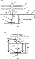
- Fig. 1 shows a MALDI ion source configuration, including a MALDI ion source 100, used by the present inventors before the development of the present invention.
- the MALDI ion source 100 shown in Fig. 1 has a sample plate holding means for holding sample material to be ionised by the MALDI ion source 100.
- the sample holding means includes a sample plate 110, which is removable from the MALDI ion source 100, for holding a crystallised mixture of sample material and light absorbing matrix in a sample spot 120, and a sample plate carrier 112, which is not removable from the MALDI ion source 100, for carrying the sample plate 110.
- the MALDI ion source 100 also has a laser (not shown) for ionising sample material by firing pulses of light, in this embodiment pulses of UV light, in the form of a pulsed laser beam 130, at the sample material. As shown in Fig. 1 , the UV light produced by the laser is focused to converge at a focal point whose position coincides with the sample spot 120.
- the MALDI ion source 100 also has a first electrode 140 and a second electrode 142 for producing an electric field to accelerate ions generated by the laser to a predetermined kinetic energy, e.g. 20 keV.
- the first and second electrodes 140, 142 are each shaped to define an aperture through which ions generated by the laser can pass through as they are accelerated by the first and second electrodes 140, 142.
- the MALDI ion source 100 also includes a housing (not shown) for containing the electrodes 140, 142 and the sample holding means.
- the housing is preferably evacuated prior to the MALDI ion source 100 being used.
- the laser fires a pulse of light at the mixture of sample material and light absorbing matrix contained in the sample spot 120 so as to eject a plume of ionised and non-ionised (i.e. neutral) sample material ("analyte") and light absorbing matrix.
- the ionised material 122 contained in this plume will generally be accelerated away by an electric field produced by the first and second electrodes 140, 142 so as to pass through the apertures in the first and second electrodes 140, 142, e.g. for subsequent detection by an ion detector.
- the non-ionised material 124 contained in this plume will generally continue to expand from the sample spot 120 until it is deposited on surfaces in the vicinity of the sample spot, e.g. surfaces of the first and second electrodes 140, 142. In general, much of the non-ionised material 124 will be deposited on a surface of the first electrode 140, but some non-ionised material 124 may also pass through the aperture in the first electrode 140 to be deposited on a surface of second electrode 142.
- the non-ionised material builds up on the surfaces in the vicinity of the sample spot, particularly on the surfaces of the first and second electrodes 140, 142, to form an insulating layer of contaminant material that may charge up over time and adversely affect the operation of the MALDI ion source 100.
- the insulating layer of contaminant material on the first and second electrodes 140, 142 can distort the electric field produced by the first and second electrodes 140, 142 such that the sensitivity or resolution of a mass spectrometer using the MALDI ion source 100 is degraded.
- the first and second electrodes 140, 142 of the MALDI ion source will generally require cleaning.
- Fig. 2 shows a MALDI ion source configuration, including a MALDI ion source 200, used by the present inventors after the development of the present invention.
- the sample holding means includes a differently shaped sample plate carrier 212, having both a first level on which the sample plate 210 is mounted and a second level on which a UV mirror 250 concave reflecting surface provided by a UV mirror 250.
- the mirror is mounted on the sample plate carrier 212 such that the reflecting surface is at a different distance from the laser for ionising sample material.
- the concave reflecting surface of the mirror 250 has a generally spherical curvature and a central axis 252.
- the sample plate carrier is configured to be moved in a plane substantially perpendicular to a beam axis 232 of the laser for ionising sample material so as to allow both the sample plate 210, and the mirror 250, to be moved into and out of the beam axis 232.
- a sample spot 220 on the sample plate 210 is moved into the beam axis 232 of the laser such that UV light from the laser is focussed to converge at a first focal point 234 whose position coincides with the sample spot 220.
- the mirror 250 is moved into the beam axis 232 of the laser such that UV light from the laser is directed on to a surface of one of the electrodes 240, 242 via the mirror 250 which reflects the UV light from the laser.
- the UV light is able to couple energy directly into contaminant material on the surface of the electrode so as to cause the contaminant material to desorb from the surface of the electrode without having to significantly heat the electrode, and without having to vent the evacuated housing of the MALDI ion source 200.
- the mirror 250 is preferably translated, e.g. continuously, in a plane substantially perpendicular to the beam axis 232 of the laser, such that the UV light from the laser is scanned across a surface of either or both of the electrodes 240, 242, preferably in two dimensions.
- the UV light from the laser is firstly focussed by one or more lenses associated with the laser (not shown) to converge at a first focal point 234 and is subsequently refocused by the mirror 250 to converge at a second focal point 236.
- the position of the second focal point 236 is at a surface of the first electrode 240.
- the position of the second focal point 236 can be other than at a surface of an electrode, e.g. to achieve a predetermined energy density at a surface of the electrode.
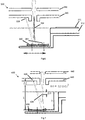
- Fig. 3 illustrates the geometry of the MALDI ion source configuration shown in Fig. 2 .
- the concave reflecting surface of the mirror 250 has a generally spherical curvature, there will be a generally linear relationship between the lateral translation of the mirror 250 (which is determined by the lateral translation of the sample plate carrier 212) and the movement of the second focal point 236 of the UV light from the laser across a surface of the electrodes 240, 242.
- the UV light from the laser can either be focused by the mirror 250 to have a minimum spot size at a surface of an electrode to maximise the energy density per pulse (as shown in Fig. 3 , where the second focal point 236 is at a surface of the first electrode 240) or can be only partially focused to allow a larger area to be irradiated per pulse.
- the most effective desorption of contaminant material can be achieved by having an energy density that is somewhere between these extremes.
- an area of 1cm 2 can be cleaned very rapidly, at approximately 80s/cm 2 .
- the area of contaminated electrode that typically needs cleaning is of the order of 10cm 2 and thus a total cleaning time for a contaminated electrode may typically be between 15 and 30 minutes.
- Figs. 4 and 5 each show a stainless steel electrode of which a 0.25mm strip has been cleaned of DHB and CHCA light absorbing matrix respectively.
- a UV spherical mirror of 25mm focal length was positioned 44mm below the plane of the sample plate such that the beam would have been focused to at a second focal point positioned at a distance of 58mm from the mirror, had it not been intercepted by a first electrode located 52mm above the mirror.
- the pulses of UV light from a laser irradiated the first electrode 6mm away from the second focal point, which allowed the 0.25mm wide strip to be cleared in a single pass of the laser.
- the majority of the contaminant material in the MALDI ion source 200 shown in Fig. 2 will be deposited towards the centre of the first electrode 240, but some will be deposited further out on the first electrode 240 and some will pass through the aperture in the first electrode 240 and be deposited on the second electrode 242. These further surfaces are at different distances from the mirror 250 and an adjustment of the focus of the UV light is required to focus the UV light such that substantially the same predetermined energy density is obtained at these surfaces.
- the predetermined energy density may be around 600 ⁇ J/mm 2 per pulse, for example.
- Fig. 6 shows a MALDI ion source configuration, including a MALDI ion source 300, which implements a first possible methodology for adjusting the focus of UV light.
- the MALDI ion source 300 shown in Fig. 6 uses two (or more) mirrors 350, 351 each having a respective concave surface with a different curvature to the other.
- the concave surfaces of the two mirrors 350, 351 both have a spherical curvature, with different focal lengths.
- the concave surface of the first mirror 350 focuses UV light from the laser to have a first focus such that the UV light has a predetermined energy density at a surface of the first electrode 340
- the concave surface of the second mirror 351 focuses UV light from the laser to have a second focus such that the UV light has the same predetermined energy density at a surface of the second electrode 342.
- Fig. 7 shows a MALDI ion source configuration, including a MALDI ion source 400, which implements a second possible methodology for adjusting the focus of UV light.
- the MALDI ion source 400 shown in Fig. 7 adjusts the focus of the UV light by adjusting the position of a lens in the path of the UV light.
- the lens is associated with the laser, wherein adjustment of the position of this lens causes a shift the position of the first focal point 434.
- the relationship between the shift in position of the second focal point 436 ( ⁇ I) and the shift in position of the first focal point 434 ( ⁇ O) is generally determined by the longitudinal magnification (ML), and can be approximated using the relation ⁇ O ⁇ I(O/I) 2 . This relation may be used to calculate a change in position of the first focal point 434 ( ⁇ O) needed to give the required shift in the second focal point 436 ( ⁇ I), to allow focused beam to be switched between different surfaces of the first and second electrodes 440, 442.
- the methods described herein may be automated and can provide rapid and very efficient cleaning of the electrodes of an ion source to be carried out, without the need for removing the ion source, venting a housing of the ion source, or even removing a sample plate from the ion source.
- a further advantage of the methods described herein is that a mirror used to reflect UV light from the laser can also be used to relay an image of at least one electrode into the object plane of a sample plate imaging system to enable the amount (or degree) of contaminant material present on the at least one electrode to be visually assessed using the sample plate imaging system.
Description
- This invention relates to methods and apparatuses for cleaning at least one surface, preferably comprising a surface of an electrode, of an ion source for generating ions of sample material in a mass spectrometer. Preferably, the present invention relates to cleaning a surface of an electrode of a MALDI ion source.
- TOF mass spectrometry is an analytical technique for measuring the mass/charge ratio of ions by accelerating ions and measuring their time of flight to an ion detector.
- In a simple form, a TOF mass spectrometer includes an ion source for generating a pulse (or burst) of ions of sample material and an ion detector for detecting ions that have travelled from the ion source to the ion detector. The ions generated by the ion source preferably have, e.g. because they have been accelerated to, a predetermined kinetic energy and so have different speeds according to their mass/charge ratio. Accordingly, as ions travel between the ion source and the ion detector, ions of different mass/charge ratios are separated by their different speeds and so are detected by the ion detector at different times, which allows their respective times of flight to be measured based on an output of the ion detector. In this way, mass spectrum data representative of the mass/charge ratio of ions of sample material can be acquired based on an output of the ion detector.
- Matrix-assisted laser desorption/ionization, often referred to as "MALDI", is an ionisation technique in which, generally, a laser is used to fire light at a (usually crystallised) mixture of sample material and light absorbing matrix so as to ionise the sample material. The sample materials used with MALDI typically include molecules such as biomolecules (e.g. proteins), large organic molecules and/or polymers. The light absorbing matrix is generally used to protect such molecules from being damaged or destroyed by light from the laser. The resulting ions, which typically have masses of several thousand Daltons, are then accelerated to high kinetic energies, typically around 20 keV. Generally, an ion source configured to generate ions by MALDI is referred to as a "MALDI ion source". A MALDI ion source typically includes a laser for ionising sample material by firing light at a mixture of the sample material and light absorbing matrix.
- MALDI is usually combined with time of flight mass spectrometry to provide "MALDI TOF" mass spectrometry in which, generally, a pulse of ions is generated by MALDI and the time of flight of the ions is then measured over distances typically of around 1-2 metres so that the mass/charge ratio of the ions can be determined.
- Measuring the time of flight of ions in modern TOF mass spectrometers, e.g. MALDI TOF mass spectrometers, typically requires a diverse range of high speed digital and analogue electronics. For example, high speed timing electronics may be used in order to accurately synchronise various high-voltage electrical pulses with the firing of a laser and the acquisition of an ion signal. Also, kV/µs slew-rate high voltage electrical pulses may be used to accelerate, gate and steer ionised molecules generated by the laser. Finally, high speed multi-bit analogue to digital converters may be used to record the output from an ion detector so that the time of flight of the ions, and therefore the mass/charge ratio of the ions, can be determined. Such high speed digital and analogue electronics are typically run for each acquisition cycle of the TOF mass spectrometer.
- Until recently, TOF mass spectrometers, e.g. MALDI TOF mass spectrometers, have used gas lasers having a repetition rate (rate at which it can fire pulses of light) of up to a few tens of Hz. More recent TOF mass spectrometers have used solid-state lasers capable of much higher repetition rates, e.g. 1 kHz or more.
- Generally, when a MALDI ion source is in use, a laser of the MALDI ion source fires a pulse of (e.g. UV) light at a mixture of sample material and light absorbing matrix contained in a sample spot so as to eject a plume of ionised and non-ionised (i.e. neutral) sample material ("analyte") and light absorbing matrix from the sample spot. The ionised material contained in this plume (mostly ions of sample material and some ions of light absorbing matrix) will generally be accelerated away by an electric field produced by electrodes of the MALDI ion source so as to pass through apertures in the electrodes, e.g. for subsequent detection by an ion detector. However, the non-ionised material contained in this plume (mostly non-ionised light absorbing matrix and some non-ionised sample material) will generally continue to expand from the sample spot until it is deposited on surfaces in the vicinity of the ion source, e.g. surfaces of the electrodes of the MALDI ion source.
- Over time, the non-ionised material builds up on the surfaces in the vicinity of the sample spot, particularly on the surfaces of the electrodes of the MALDI ion source, to form an insulating layer of contaminant material that may charge up over time and adversely affect the operation of the MALDI ion source. In particular, the insulating layer of contaminant material on the electrodes can distort the electric field produced by the electrodes such that the sensitivity or resolution of a mass spectrometer using the MALDI ion source is degraded. At this point the electrodes of the MALDI ion source will generally require cleaning.
- For many years the principal method of cleaning the electrodes of a MALDI ion source was to vent and open an evacuated housing containing the electrodes to allow the electrodes to be cleaned in situ or removed completely for thorough cleaning. In both cases, in addition to the cleaning time, several hours were generally required to restore a vacuum to the housing of the MALDI ion source (once closed) and to perform high voltage conditioning, instrument tuning and mass calibration procedures that are generally necessary for the MALDI ion source to be used in mass spectrometry.
- In many applications (e.g. biochemistry) there is a growing requirement for higher throughput mass spectrometers, which can now be realised by the introduction of MALDI ion sources capable of running at repetition rates of 1 kHz or over. This has increased the rate of contamination build up on the electrodes of MALDI ion sources, and the frequency with which they must be cleaned, to such an extent that it is generally no longer practical to vent the MALDI ion source every time its electrodes require cleaning.
- These considerations make it desirable to find an effective method to clean the electrodes of MALDI ion sources without requiring an evacuated housing of the MALDI ion source to be vented.
- Various methods have been considered to clean the electrodes of MALDI ion sources without the need to vent an evacuated housing of the MALDI ion source.
- For example, in
GB2398923 - In
US 7,541,597 , Holle and Przybyla propose a method of cleaning electrodes of MALDI ion sources by etching with reactive ions produced by an electrically generated gas discharge in a specially admitted reactant gas, which can be automatically carried out by using a specially designed electrode place in place of a standard sample plate carrier and admitting a reactant gas. - The above mentioned methods share a disadvantage in that a special apparatus has to be inserted in place of a standard sample plate such that the precise location of sample material may be lost, which may be important in certain imaging applications. A further disadvantage may be the interruption of automated runs for mass spectrometers capable of automatically loading several sample plates.
- Methods of cleaning the electrodes of MALDI ion sources have also been proposed in which the electrodes are heated to temperatures of up to 250ºC, e.g. using contact heaters (
US 6953928, Vestel et al. ) or with infrared laser radiation (GB2457362, Holle and Hohndorf - The present invention has been devised in light of the above considerations.
-
US Patent No. 5118937 discloses a process for the laser desorption of analyte molecular ions, especially of biomolecules, from a specimen. -
US2009/0200457A1 disclose cleaning ion acceleration diaphragms by temporarily heating the diaphragms in an ion source that generates ions by matrix-assisted laser desorption. - In general, the invention relates to a method of cleaning at least one surface of an ion source for a mass spectrometer by directing light on to the surface such that contaminant material is desorbed from the surface. In this way, the at least one surface of the ion source can be cleaned in a simple manner, without having to significantly heat the surface and without having to vent an evacuated housing of the ion source.
- In the context of this application, "light" is preferably taken to mean electromagnetic radiation (having any wavelength). "Desorption" of a substance from a surface is preferably mean the releasing/removal of that substance from the surface.
- A first aspect of the invention provides a method of cleaning at least one surface of an ion source in a mass spectrometer, as set out in
claim 1. - By directing UV light on to the at least one surface of the ion source, the UV light is able to couple energy directly into contaminant material on the at least one surface so as to cause the contaminant material to desorb from the at least one surface without having to significantly heat the at least one surface. This mechanism is different from, for example, the method proposed in
GB2457362 - Preferably, the directing UV light on to the at least one surface of the ion source is such that there is substantially no heating of the at least one surface. Here, "substantially no heating" may be taken to mean that the temperature at the at least one surface of the ion source remains less than 80 degrees Celsius, more preferably that the temperature at the at least one surface of the ion source remains less than 60 degrees Celsius. This is different from, for example, the method proposed in
GB2457362 - The at least one surface of the ion source comprises a surface of an electrode of the ion source. In other words, the method includes directing UV light on to a surface of an electrode of the ion source such that contaminant material is desorbed from the surface of the electrode. As explained above, build up of contaminant material on the electrodes of ion sources is a particular problem in mass spectrometers. However, contaminant material can also build up on other surfaces of ion sources, e.g. surfaces in the vicinity of a sample spot of the ion source.
- By UV ("ultra violet") light, it is preferably meant light having a wavelength of 450nm or less, more preferably less than 400 nm or less, more preferably 390 nm or less (with no minimum wavelength). However, the UV light may have a wavelength of 10 nm or more, 100 nm or more, 200 nm or more or 300 nm or more. Accordingly, the UV light may have a wavelength in the range 10 nm to 390 nm, 400 nm or 450 nm; 100 nm to 390 nm, 400 nm or 450 nm; 200 nm to 390 nm, 400 nm or 450 nm; or 300 nm to 390 nm, 400 nm or 450 nm. Contaminant material, which may include light absorbing matrices such as DCTB, DHB, SA, DTL or CHCA, has been found to be particularly absorbent to light having a wavelength in these ranges, thereby allowing the light to couple energy directly into contaminant material on the at least one surface of the ion source so as to cause the contaminant material to desorb from the at least one surface without having to significantly heat the at least one surface.
- The contaminant material may, for example, include or be non-ionised sample material and/or light absorbing matrix such as DCTB (T-2-(3-(4-t-Butyl-phenyl)-2-methyl-2-propenylidene)malononitrile), DHB (2,5-dihydroxybenzoic acid), SA (sinapinic acid), DTL (1,8,9-anthrecenetriol (dithranol)) or CHCA (α-Cyano-4-hydroxycinnamic acid). For example, the non-ionised sample material and/or the non-ionised light absorbing matrix could originate from a mixture of sample material and light absorbing matrix previously used in the ion source.
- The directing UV light on to the at least one surface of the ion source includes reflecting UV light produced by the laser for ionising sample material, as will be described below.
- The ion source includes a laser for ionising sample material by firing light at the sample material. Preferably, the laser is for ionising sample material by firing pulses of light at the sample material.
- If the contaminant material was produced by firing light from the laser at the sample material (so as to desorb the contaminant material from the sample material), then the UV light produced by the laser and directed on to the at least one surface of the ion source should be energetic enough to readily desorb the contaminant material from the at least one surface, without having to significantly heat the at least one surface.
- The UV light directed on to the at least one surface of the ion source is produced by the laser for ionising sample material by firing light at the sample material. In other words, the laser for ionising the sample material is the light source that produces the UV light that is directed on to the at least one surface of the ion source. This is a particularly elegant way of directing UV light on to the at least one surface of the ion source that is of a second wavelength that is approximately equal to a first wavelength of light fired by the laser for ionising the sample material.
- Directing UV light on to the at least one surface of the ion source includes reflecting the UV light produced by the laser for ionising sample material onto the at least one surface of the ion source via a reflecting surface. The reflecting surface is preferably provided by a mirror. Reflecting the UV light in this way is particularly useful, since the UV light produced by the laser can be directed on to the at least one electrode of the ion source without moving the laser.
- The directing UV light on to the at least one surface of the ion source includes moving the reflecting surface into a path of the UV light produced by the laser so that the reflecting surface reflects the UV light. For example, the path of the UV light may be defined by a beam axis of the laser, and the method may include moving the reflecting surface into a beam axis of the laser. Here, "beam axis" preferably means an axis extending in a direction of travel of UV light produced by the laser.
- Preferably, the reflecting surface is concave. In this way, the concave reflecting surface may be used to focus the UV light, in addition to directing the UV light. The curvature of the concave reflecting surface is preferably spherical, but may be parabolic or have any other suitable concave profile.
- Preferably, the method includes moving the reflecting surface to scan UV light produced by the laser across the at least one surface of the ion source. Preferably the UV light is scanned across the at least one surface of the ion source in two dimensions. In this way, contaminant material can be desorbed from different locations across the at least one surface of the ion source. If the reflecting surface is concave, this scanning of UV light may be achieved by translating the concave reflecting surface in a plane, e.g. a plane that is substantially perpendicular to a beam axis of a light source for producing the UV light. As explained above, this light source may be a laser for ionising sample material.
- Preferably, the reflecting surface is mounted on a sample holding means for holding sample material to be ionised by the ion source. In this way, both the reflecting surface, and sample material held by the sample holding means, can be moved into (and out from) a path of the UV light in place of sample material, by moving the sample holding means. The directing UV light on to the at least one surface of the ion source may include moving the sample holding means so as to move the reflecting surface into a path of the UV light so that the reflecting surface reflects the UV light.
- Preferably, the reflecting surface is mounted on the sample holding means such that the reflecting surface is at a different distance from a laser for ionising sample material. This may be helpful in allowing the reflecting surface to reflect light from the laser on to the at least one surface of the ion source and/or focus the light to have a predetermined energy density at the at least one surface of the ion source.
- The sample holding means may include a sample plate for holding sample material in one or more "sample spots". The sample holding means may include a sample plate carrier for carrying a sample plate. Preferably the reflecting surface is mounted on a part of the sample holding means that is configured to be removed from the ion source, e.g. the sample plate, thereby allowing the reflecting surface to be cleaned more easily.
- Preferably, the method includes using the reflecting surface to visually assess the amount of contaminant material present on the at least one surface of the ion source, e.g. using a sample plate imaging system. This is an additional function which may be provided by the reflecting surface.
- Preferably the method includes focussing the UV light such that the UV light has a predetermined energy density at the at least one surface of the ion source. The UV light may be focussed, for example, by a concave reflecting surface as described above, and/or by some other means for focussing the UV light, e.g. a lens. Also, the UV light may be focussed by a combination of a concave or planar reflecting surface and a lens.
- Preferably, the method includes directing pulses of UV light on to the at least one surface of the ion source. The pulses of UV light may be produced, for example, by a laser for ionising sample material by firing pulses of light at the sample material. By directing pulses of UV light on to the at least one surface of the ion source, heating of the at least one surface may be reduced compared with directing a continuous stream of UV light on to the at least one surface, because heat is given an opportunity to dissipate between the pulses.
- If the method includes directing pulses of UV light on to the at least one surface of the ion source, the method preferably further includes focussing the pulses of UV light such that each pulse of UV light has an energy density at the at least one surface of the ion source that is 1µJ/mm2 or more, 10µJ/mm2 or more, 100µJ/mm2 or more, 200µJ/mm2 or more, 400µJ/mm2 or more or 500µJ/mm2 or more; and/or 2000µJ/mm2 or less, 1000µJ/mm2 or less, 800µJ/mm2 or less or 600µJ/mm2 or less. These values may be combined in any combination. For example, each pulse of UV light may have an energy density at a surface of the at least one surface of the ion source that is in the range 400µJ/mm2 to 800µJ/mm2. Such energy densities have been found to effectively desorb contaminant material with a single pulse of light.
- Preferably, the method includes directing UV light on to a first surface and a second surface of the ion source such that contaminant material is desorbed from the first and second surfaces. Preferably, the first surface is a surface of a first electrode of the ion source and the second surface is a surface of a second electrode of the ion source. The first and second surfaces may be at different distances e.g. from a sample spot. Preferably, the UV light is directed on to the first and second surfaces at different times, e.g. by scanning the UV light across one surface then the other surface, rather than simultaneously.
- Preferably, the method includes adjusting the focus of the UV light between a first focus and a second focus. Preferably, the method further includes directing UV light having the first focus onto a first surface of the ion source (which may be a surface of a first electrode of the ion source) and directing UV light having the second focus onto a second surface of the ion source (which may be a surface of a second electrode of the ion source). Preferably the first focus is such that the UV light is has a first predetermined energy density at the surface of the first surface. Preferably the second focus is such that the UV light has a second predetermined energy density at the surface of the second surface. Preferably, the first and second predetermined energy densities are approximately equal. Here, "approximately equal" preferably means equal to the extent that there is a percentage difference (or "error") of no more than 50%, 40%, 30%, 20%, 10%, 5%, 2% or 1%.
- The focus of the UV light may be adjusted by directing UV light (which is produced by a laser for ionising sample material) on to the at least one surface of the ion source using at least two concave reflecting surfaces, each concave reflecting surface having a different curvature, e.g. a different focal length. Any of the features described above in connection with a reflecting surface may apply to each of the at least two reflecting surfaces. Thus, the directing UV light on to the at least one surface of the ion source may include directing UV light having a first focus on to a first surface via a first concave reflecting surface and directing UV light having a second focus on to a second surface via a second concave reflecting surface. Similarly, the directing UV light on to the at least one surface of the ion source may include moving the first concave reflecting surface into a path of the UV light and moving the second concave reflecting surface into a path of the UV light.
- However, the focus of the UV light may be adjusted in other ways. For example, in some embodiments, the focus of the UV light may be adjusted by adjusting a position of a lens in a path of the UV light (which may, for example, be produced by a laser for ionising sample material). The lens may be included, or associated with, a laser for ionising sample material, for example.
- A second aspect of the invention relates to an apparatus for carrying out a method according to the first aspect of the invention.
- Accordingly, a second aspect of the invention provides an ion source for generating ions in a mass spectrometer as set out in claim 15.
- The ion source may have any feature described in connection with any above aspect of the invention and/or may be configured to, or have means for, implementing any method step described in connection with any above aspect of the invention.
- Preferably, the reflecting surface is configured to be moved to scan UV light from a source of UV light across the at least one surface of the ion source.
- As another example, the ion source preferably includes means for focussing the UV light such that the UV light has a predetermined energy density at the at least one surface of the ion source and/or means for adjusting the focus of the UV light between a first focus and a second focus and/or means for directing UV light having the first focus onto a first surface of the ion source and directing UV light having a second focus onto a second surface of the ion source. Preferably, the means for adjusting the focus of the UV light includes at least two concave reflecting surfaces, each concave reflecting surface having a different curvature. Alternatively, the means for adjusting the focus of the UV light may include means for adjusting a position of a lens in a path of the UV light.
- In any above aspect, the ion source may be a MALDI ion source. For a MALDI ion source, the sample material may include biomolecules (e.g. proteins), organic molecules and/or polymers. The sample material may be included in a (preferably crystallised) mixture of sample material and light absorbing matrix. Cleaning electrodes has been found to be a particular concern for MALDI ion sources. However, the electrodes of other types of ion source may also need cleaning.
- In any above aspect, the at least one surface of the ion source comprises a surface of an electrode of the ion source. The electrode may be a first electrode of the ion source, where "first electrode" is taken to mean an electrode closest to a sample spot (or a sample holding means) of the ion source. The electrode may be an acceleration electrode for producing an electric field to accelerate ions generated by the ion source to a predetermined kinetic energy, e.g. to provide a pulse of ions. The electrode may additionally, or alternatively, be for guiding the ions. Cleaning acceleration electrodes has been found to be a particular concern in ion sources for mass spectrometers, particularly MALDI ion sources. However, other types of electrode and other types of surface may also need cleaning.
- In any above aspect, the ion source may include a sample holding means for holding sample material to be ionised by the ion source. The sample holding means may include a sample plate for holding sample material in one or more "sample spots". The sample holding means may include a sample plate carrier for carrying a sample plate. The sample plate is preferably configured to be removed from the ion source whereas the sample plate carrier may be non-removably mounted within the ion source.
- In any above aspect, the ion source preferably includes a housing for containing the at least one electrode and/or a sample holding means. The housing is preferably configured to be evacuated, i.e. configured to contain a vacuum. Preferably, in an above described method, light (preferably UV light) is directed on to the at least one electrode of the ion source such that contaminant material is desorbed from the at least one electrode whilst the housing is evacuated. In other words, the housing is preferably not vented for the cleaning of the at least one electrode.
- In any above aspect, the ion source may be included in a TOF mass spectrometer, more preferably a MALDI TOF mass spectrometer. The mass spectrometer may include an ion detector for detecting ions, e.g. a pulse of ions, generated by the ion source.
- The invention also includes any combination of the aspects and preferred features described except where such a combination is clearly impermissible or expressly avoided.
- Embodiments of these proposals are discussed below, with reference to the accompanying drawings in which:
-
Fig. 1 shows a MALDI ion source configuration used by the present inventors before the development of the present invention. -
Fig. 2 shows a MALDI ion source configuration used by the present inventors after the development of the present invention. -
Fig. 3 illustrates the geometry of the MALDI ion source configuration shown inFig. 2 . -
Fig. 4 shows a stainless steel electrode of which a 0.25mm strip has been cleaned of DHB light absorbing matrix. -
Fig. 5 shows a stainless steel electrode of which a 0.25mm strip has been cleaned of CHCA light absorbing matrix. -
Fig. 6 shows a MALDI ion source configuration which implements a first possible methodology for adjusting the focus of UV light. -
Fig. 7 shows a MALDI ion source configuration which implements a second possible methodology for adjusting the focus of UV light. -
Fig. 1 shows a MALDI ion source configuration, including aMALDI ion source 100, used by the present inventors before the development of the present invention. - The
MALDI ion source 100 shown inFig. 1 has a sample plate holding means for holding sample material to be ionised by theMALDI ion source 100. The sample holding means includes asample plate 110, which is removable from theMALDI ion source 100, for holding a crystallised mixture of sample material and light absorbing matrix in asample spot 120, and asample plate carrier 112, which is not removable from theMALDI ion source 100, for carrying thesample plate 110. - The
MALDI ion source 100 also has a laser (not shown) for ionising sample material by firing pulses of light, in this embodiment pulses of UV light, in the form of apulsed laser beam 130, at the sample material. As shown inFig. 1 , the UV light produced by the laser is focused to converge at a focal point whose position coincides with thesample spot 120. - The
MALDI ion source 100 also has afirst electrode 140 and asecond electrode 142 for producing an electric field to accelerate ions generated by the laser to a predetermined kinetic energy, e.g. 20 keV. The first andsecond electrodes second electrodes - The
MALDI ion source 100 also includes a housing (not shown) for containing theelectrodes MALDI ion source 100 being used. - In use, the laser fires a pulse of light at the mixture of sample material and light absorbing matrix contained in the
sample spot 120 so as to eject a plume of ionised and non-ionised (i.e. neutral) sample material ("analyte") and light absorbing matrix. The ionisedmaterial 122 contained in this plume (mostly ions of sample material and some ions of light absorbing matrix) will generally be accelerated away by an electric field produced by the first andsecond electrodes second electrodes non-ionised material 124 contained in this plume (mostly non-ionised light absorbing matrix and some non-ionised sample material) will generally continue to expand from thesample spot 120 until it is deposited on surfaces in the vicinity of the sample spot, e.g. surfaces of the first andsecond electrodes non-ionised material 124 will be deposited on a surface of thefirst electrode 140, but somenon-ionised material 124 may also pass through the aperture in thefirst electrode 140 to be deposited on a surface ofsecond electrode 142. - Over time, the non-ionised material builds up on the surfaces in the vicinity of the sample spot, particularly on the surfaces of the first and
second electrodes MALDI ion source 100. In particular, the insulating layer of contaminant material on the first andsecond electrodes second electrodes MALDI ion source 100 is degraded. At this point the first andsecond electrodes -
Fig. 2 shows a MALDI ion source configuration, including aMALDI ion source 200, used by the present inventors after the development of the present invention. - Many features of the
MALDI ion source 200 shown inFig. 2 are the same as those of theMALDI ion source 100 shown inFig. 1 . These features have been given corresponding reference numerals and need not be discussed in further detail. - As can be seen from
Fig. 2 , the sample holding means includes a differently shapedsample plate carrier 212, having both a first level on which thesample plate 210 is mounted and a second level on which aUV mirror 250 concave reflecting surface provided by aUV mirror 250. Thus, the mirror is mounted on thesample plate carrier 212 such that the reflecting surface is at a different distance from the laser for ionising sample material. In this example, the concave reflecting surface of themirror 250 has a generally spherical curvature and acentral axis 252. - The sample plate carrier is configured to be moved in a plane substantially perpendicular to a
beam axis 232 of the laser for ionising sample material so as to allow both thesample plate 210, and themirror 250, to be moved into and out of thebeam axis 232. - In use to generate ions, a
sample spot 220 on thesample plate 210 is moved into thebeam axis 232 of the laser such that UV light from the laser is focussed to converge at a firstfocal point 234 whose position coincides with thesample spot 220. - In use to clean one of the
electrodes mirror 250 is moved into thebeam axis 232 of the laser such that UV light from the laser is directed on to a surface of one of theelectrodes mirror 250 which reflects the UV light from the laser. Advantageously, the UV light is able to couple energy directly into contaminant material on the surface of the electrode so as to cause the contaminant material to desorb from the surface of the electrode without having to significantly heat the electrode, and without having to vent the evacuated housing of theMALDI ion source 200. - Once located in the
beam axis 232 of the laser, themirror 250 is preferably translated, e.g. continuously, in a plane substantially perpendicular to thebeam axis 232 of the laser, such that the UV light from the laser is scanned across a surface of either or both of theelectrodes - As shown in
Fig. 2 , the UV light from the laser is firstly focussed by one or more lenses associated with the laser (not shown) to converge at a firstfocal point 234 and is subsequently refocused by themirror 250 to converge at a secondfocal point 236. As shown inFig. 2 , the position of the secondfocal point 236 is at a surface of thefirst electrode 240. However, in other preferred embodiments, the position of the secondfocal point 236 can be other than at a surface of an electrode, e.g. to achieve a predetermined energy density at a surface of the electrode. -
Fig. 3 illustrates the geometry of the MALDI ion source configuration shown inFig. 2 . - Because, in this example, the concave reflecting surface of the
mirror 250 has a generally spherical curvature, there will be a generally linear relationship between the lateral translation of the mirror 250 (which is determined by the lateral translation of the sample plate carrier 212) and the movement of the secondfocal point 236 of the UV light from the laser across a surface of theelectrodes - In more detail, as can be seen from
Fig. 3 , the secondfocal point 236 of the UV light from the laser will generally be displaced laterally from thebeam axis 232 of the laser by a distance given by D=dMT, where d is the lateral displacement of thecentral axis 252 of themirror 250 from thebeam axis 232 of the laser and MT is the transverse magnification of themirror 250. The transverse magnification MT of themirror 250 may be given by MT=I/O, where O is an object distance for the mirror 250 (which inFig. 3 is the distance along thebeam axis 232 of the laser between themirror 250 and the first focal point 234) and I is the image distance for the mirror 250 (which inFig. 3 is the distance along thebeam axis 232 of the laser between themirror 250 and the second focal point 236). A value for the focal length f of themirror 250 may be calculated for given values of I and O using the thin lens equation f=O.I/(O+I) and the radius of curvature R of themirror 250 by the equation R=2f. - The UV light from the laser can either be focused by the
mirror 250 to have a minimum spot size at a surface of an electrode to maximise the energy density per pulse (as shown inFig. 3 , where the secondfocal point 236 is at a surface of the first electrode 240) or can be only partially focused to allow a larger area to be irradiated per pulse. In practice, it has been found that the most effective desorption of contaminant material can be achieved by having an energy density that is somewhere between these extremes. In particular, it has been found that, for a laser producing pulses of UV light each having an energy of 40µJ per pulse, efficient cleaning can be achieved by focussing the UV light at a surface of an electrode to have a 1/e2 diameter of 0.3 mm, so as to clean a circle of diameter 0.25mm per pulse. This corresponds to an energy density of 40µJ/π(0.3/2)2∼600µJ/mm2 per pulse. - By cleaning a circle of diameter of 0.25mm per pulse, an area of 1cm2 (=100mm2) can be cleaned with approximately 2500 pulses (100/π(0.25/2)2). Hence, for a sample plate carrier moving at 5mm/s and laser repetition rate of 30 pulses/s, an area of 1cm2 can be cleaned very rapidly, at approximately 80s/cm2. The area of contaminated electrode that typically needs cleaning is of the order of 10cm2 and thus a total cleaning time for a contaminated electrode may typically be between 15 and 30 minutes.
-
Figs. 4 and 5 each show a stainless steel electrode of which a 0.25mm strip has been cleaned of DHB and CHCA light absorbing matrix respectively. For the examples shown inFigs. 4 and 5 , a UV spherical mirror of 25mm focal length was positioned 44mm below the plane of the sample plate such that the beam would have been focused to at a second focal point positioned at a distance of 58mm from the mirror, had it not been intercepted by a first electrode located 52mm above the mirror. Thus the pulses of UV light from a laser irradiated the first electrode 6mm away from the second focal point, which allowed the 0.25mm wide strip to be cleared in a single pass of the laser. - The majority of the contaminant material in the
MALDI ion source 200 shown inFig. 2 will be deposited towards the centre of thefirst electrode 240, but some will be deposited further out on thefirst electrode 240 and some will pass through the aperture in thefirst electrode 240 and be deposited on thesecond electrode 242. These further surfaces are at different distances from themirror 250 and an adjustment of the focus of the UV light is required to focus the UV light such that substantially the same predetermined energy density is obtained at these surfaces. The predetermined energy density may be around 600µJ/mm2 per pulse, for example. - This adjustment of focus can readily be achieved using various different methodologies, which may be combined.
-
Fig. 6 shows a MALDI ion source configuration, including aMALDI ion source 300, which implements a first possible methodology for adjusting the focus of UV light. - Many features of the
MALDI ion source 300 shown inFig. 6 are the same as those of theMALDI ion source 200 shown inFig. 2 . These features have been given corresponding reference numerals and need not be discussed in further detail. - The
MALDI ion source 300 shown inFig. 6 uses two (or more) mirrors 350, 351 each having a respective concave surface with a different curvature to the other. In this example, the concave surfaces of the twomirrors first mirror 350 focuses UV light from the laser to have a first focus such that the UV light has a predetermined energy density at a surface of thefirst electrode 340, whereas the concave surface of thesecond mirror 351 focuses UV light from the laser to have a second focus such that the UV light has the same predetermined energy density at a surface of thesecond electrode 342. -
Fig. 7 shows a MALDI ion source configuration, including aMALDI ion source 400, which implements a second possible methodology for adjusting the focus of UV light. - Many features of the
MALDI ion source 400 shown inFig. 7 are the same as those of theMALDI ion source 200 shown inFig. 2 . These features have been given corresponding reference numerals and need not be discussed in further detail. - The
MALDI ion source 400 shown inFig. 7 adjusts the focus of the UV light by adjusting the position of a lens in the path of the UV light. In this example, the lens is associated with the laser, wherein adjustment of the position of this lens causes a shift the position of the firstfocal point 434. The relationship between the shift in position of the second focal point 436 (ΔI) and the shift in position of the first focal point 434 (ΔO) is generally determined by the longitudinal magnification (ML), and can be approximated using the relation ΔO∼ΔI(O/I)2. This relation may be used to calculate a change in position of the first focal point 434 (ΔO) needed to give the required shift in the second focal point 436 (ΔI), to allow focused beam to be switched between different surfaces of the first andsecond electrodes - The methods described herein may be automated and can provide rapid and very efficient cleaning of the electrodes of an ion source to be carried out, without the need for removing the ion source, venting a housing of the ion source, or even removing a sample plate from the ion source.
- A further advantage of the methods described herein is that a mirror used to reflect UV light from the laser can also be used to relay an image of at least one electrode into the object plane of a sample plate imaging system to enable the amount (or degree) of contaminant material present on the at least one electrode to be visually assessed using the sample plate imaging system.
- The methods described herein have been found to be effective in cleaning all common light absorbing matrixes from electrodes even when an appreciable layer of contaminant material has been allowed to build up.
- Although certain parameters (e.g. distances, energy densities etc) have been provided in connection with the methods described herein, it is to be appreciated that the parameters used to obtain the most efficient cleaning will, in general, depend on the ion source to be cleaned.
- When used in this specification and claims, the terms "comprises" and "comprising" and variations thereof mean that the specified features, steps or integers are included. The terms are not to be interpreted to exclude the presence of other features, steps or integers.
- The features disclosed in the foregoing description, or in the following claims, or in the accompanying drawings, expressed in their specific forms or in terms of a means for performing the disclosed function, or a method or process for obtaining the disclosed results, as appropriate, may, separately, or in any combination of such features, be utilised for realising the invention in diverse forms thereof.
- While the invention has been described in conjunction with the exemplary embodiments described above, many equivalent modifications and variations will be apparent to those skilled in the art when given this disclosure, without departing from the broad concepts disclosed. It is therefore intended that the scope of the patent granted hereon be limited only by the appended claims, as interpreted with reference to the description and drawings, and not by limitation of the embodiments described herein.
- For example, whilst the present invention has been explained in connection with cleaning the surfaces of electrodes of MALDI ion sources, it is thought the same principles would apply to cleaning other types of surfaces and other types of ion source.
Claims (13)
- A method of cleaning at least one surface of an ion source (200, 300, 400) in a mass spectrometer, wherein the at least one surface of the ion source comprises a surface of an electrode (240, 242, 340, 342, 440, 442) of the ion source, wherein the ion source includes a laser for ionising sample material by firing UV light at the sample material, wherein the method of cleaning includes:directing UV light on to the at least one surface of the ion source such that contaminant material is desorbed from the at least one surface;wherein the UV light directed on to the at least one surface of the ion source is produced by the laser for ionising sample material;wherein the directing UV light on to the at least one surface of the ion source includes reflecting the UV light produced by the laser for ionising sample material onto the at least one surface of the ion source via a reflecting surface (250, 350, 351, 450);wherein the directing UV light on to the at least one surface of the ion source includes moving the reflecting surface into a path of the UV light produced by the laser so that the reflecting surface reflects the UV light.
- A method according to claim 1 wherein the method includes moving the reflecting surface to scan UV light produced by the laser across the at least one surface of the ion source.
- A method according to claim 1 or claim 2, wherein the reflecting surface is concave.
- A method according to any one of claims 1 to 3, wherein the reflecting surface is mounted on a sample holding means (212, 312) for holding sample material to be ionised by the ion source.
- A method according to any one of claims 1 to 4 wherein the method includes using the reflecting surface to visually assess the amount of contaminant material present on the at least one surface of the ion source.
- A method according to any one of the previous claims wherein the method includes focussing the UV light such that the UV light has a predetermined energy density at the at least one surface of the ion source.
- A method according to any one of the previous claims wherein the method includes:directing pulses of UV light on to the at least one surface of the ion source; andfocussing the pulses of UV light such that each pulse of UV light has an energy density at the at least one surface of the electrode of the ion source that is from 400µJ/mm2 to 1000µJ/mm2.
- A method according to any one of the previous claims wherein the method includes:adjusting the focus of the UV light between a first focus and a second focus; anddirecting UV light having the first focus onto a first surface of the ion source and directing UV light having the second focus onto the second surface of the ion source.
- A method according to claim 10 wherein the focus of the UV light is adjusted by directing UV light on to the at least one surface of the ion source using at least two concave reflecting surfaces (350, 351), each concave reflecting surface having a different curvature, or
wherein the focus of the UV light is adjusted by adjusting a position of a lens in a path of the UV light. - A method according to any one of the previous claims wherein the method includes at least one of:(a) directing light on to the at least one surface of the ion source such that the light couples energy directly into contaminant material on the at least one surface of the ion source such that contaminant material is desorbed from the surface;(b) directing light on to the at least one surface of the ion source such that contaminant material is desorbed from the at least one surface such that there is substantially no heating of the at least one surface; and(c) directing light on to the at least one surface of the ion source such that contaminant material is desorbed from the at least one surface, wherein the light directed on to the at least one surface of the ion source has a wavelength at which the contaminant material is absorbent.
- A method according to any one of the previous claims wherein the ion source is a MALDI ion source and the ion source is included in a TOF mass spectrometer.
- A method according to any one of the previous claims wherein the ion source includes a first electrode (240, 340, 440) that is an acceleration electrode for producing an electric field to accelerate ions generated by the ion source to a predetermined kinetic energy, wherein the at least one surface of the ion source includes a surface of the first electrode of the ion source.
- An ion source (200, 300, 400) for generating ions in a mass spectrometer, the ion source having:a laser for ionising sample material by firing light at the sample material;means (250, 350, 351, 450) for directing UV light produced by the laser for ionising sample material on to at least one surface of the ion source such that contaminant material is desorbed from the at least one surface;wherein the at least one surface of the ion source comprises a surface of an electrode (240, 242, 340, 342, 440, 442) of the ion source;wherein the means for directing UV light includes a reflecting surface for directing the UV light on to the at least one surface of the ion source via the reflecting surface;wherein the reflecting surface is configured to be moved into a path of the UV light produced by the laser so that the reflecting surface reflects the UV light.
Applications Claiming Priority (2)
| Application Number | Priority Date | Filing Date | Title |
|---|---|---|---|
| GB1013015.1A GB2486628B (en) | 2010-08-02 | 2010-08-02 | Methods and apparatuses for cleaning at least one surface of an ion source |
| PCT/GB2011/001139 WO2012017190A1 (en) | 2010-08-02 | 2011-07-28 | Methods and apparatuses for cleaning at least one surface of an ion source |
Publications (2)
| Publication Number | Publication Date |
|---|---|
| EP2601671A1 EP2601671A1 (en) | 2013-06-12 |
| EP2601671B1 true EP2601671B1 (en) | 2018-09-05 |
Family
ID=42799504
Family Applications (1)
| Application Number | Title | Priority Date | Filing Date |
|---|---|---|---|
| EP11749475.7A Active EP2601671B1 (en) | 2010-08-02 | 2011-07-28 | Methods and apparatuses for cleaning at least one surface of an ion source |
Country Status (6)
| Country | Link |
|---|---|
| US (1) | US9468953B2 (en) |
| EP (1) | EP2601671B1 (en) |
| JP (1) | JP5848765B2 (en) |
| CN (1) | CN103053006B (en) |
| GB (1) | GB2486628B (en) |
| WO (1) | WO2012017190A1 (en) |
Families Citing this family (9)
| Publication number | Priority date | Publication date | Assignee | Title |
|---|---|---|---|---|
| WO2012170093A2 (en) * | 2011-03-25 | 2012-12-13 | Exxonmobil Upstream Research Company | Autonomous detection of chemical plumes |
| JP6316041B2 (en) * | 2014-03-18 | 2018-04-25 | 株式会社東芝 | Sputtering neutral particle mass spectrometer |
| GB2530768B (en) * | 2014-10-01 | 2019-07-17 | Kratos Analytical Ltd | Method and apparatuses relating to cleaning an ion source |
| DE102016101908B4 (en) | 2016-02-03 | 2017-11-02 | Dengler Tubetec Gmbh | Apparatus and method for bending pipes |
| CN105728398A (en) * | 2016-04-15 | 2016-07-06 | 淮安信息职业技术学院 | Automatic flight surface cleaning robot for photovoltaic array |
| EP3567625A1 (en) * | 2018-05-09 | 2019-11-13 | Helmholtz Zentrum München - Deutsches Forschungszentrum für Gesundheit und Umwelt (GmbH) | Device and method for mass spectroscopic analysis of particles |
| GB201809901D0 (en) * | 2018-06-15 | 2018-08-01 | Ascend Diagnostics Ltd | Improvements in and relating to mass spectrometers |
| CN112605069B (en) * | 2020-12-15 | 2021-11-02 | 暨南大学 | Automatic cleaning device for cleaning ion source pole piece of mass spectrometer |
| CN112676270B (en) * | 2020-12-24 | 2022-02-08 | 暨南大学 | Cleaning device for mass spectrometer pole piece and method for cleaning mass spectrometer pole piece |
Family Cites Families (21)
| Publication number | Priority date | Publication date | Assignee | Title |
|---|---|---|---|---|
| JPH01204426A (en) | 1988-02-10 | 1989-08-17 | Nec Corp | Method and apparatus for cleaning surface of solid |
| GB2236186B (en) * | 1989-08-22 | 1994-01-05 | Finnigan Mat Gmbh | Process and device for laser desorption of analyte molecular ions, especially of biomolecules |
| JPH07318552A (en) * | 1994-05-27 | 1995-12-08 | Hitachi Ltd | Gas chromatograph and gas chromatographic mass spectrometer |
| US5654545A (en) * | 1995-09-19 | 1997-08-05 | Bruker-Franzen Analytik Gmbh | Mass resolution in time-of-flight mass spectrometers with reflectors |
| FR2752386B1 (en) * | 1996-08-14 | 1998-09-11 | Commissariat Energie Atomique | METHOD FOR CLEANING OR DECONTAMINATION OF AN OBJECT USING AN ULTRAVIOLET LASER BEAM AND DEVICE FOR IMPLEMENTING IT |
| JP3596397B2 (en) | 1999-12-28 | 2004-12-02 | ウシオ電機株式会社 | Dry cleaning equipment |
| US6500268B1 (en) * | 2000-08-18 | 2002-12-31 | Silicon Genesis Corporation | Dry cleaning method |
| GB0021902D0 (en) * | 2000-09-06 | 2000-10-25 | Kratos Analytical Ltd | Ion optics system for TOF mass spectrometer |
| US7274015B2 (en) * | 2001-08-08 | 2007-09-25 | Sionex Corporation | Capacitive discharge plasma ion source |
| US7405397B2 (en) | 2002-03-28 | 2008-07-29 | Mds Sciex Inc. | Laser desorption ion source with ion guide coupling for ion mass spectroscopy |
| JP4161608B2 (en) * | 2002-04-15 | 2008-10-08 | 株式会社日立製作所 | Dangerous goods detection device |
| US7297942B2 (en) | 2003-01-15 | 2007-11-20 | Bruker Daltonik, Gmbh | Method and device for cleaning desorption ion sources |
| JP3795023B2 (en) * | 2003-03-04 | 2006-07-12 | 三菱重工業株式会社 | Time-of-flight mass spectrometer |
| US6762405B1 (en) | 2003-05-30 | 2004-07-13 | Photonics Industries International, Inc. | Matrix assisted laser ionization system |
| US6953928B2 (en) | 2003-10-31 | 2005-10-11 | Applera Corporation | Ion source and methods for MALDI mass spectrometry |
| US6958480B1 (en) * | 2004-06-25 | 2005-10-25 | The Regents Of The University Of California | Sample desorption/ionization from mesoporous silica |
| EP1781425A2 (en) * | 2004-07-09 | 2007-05-09 | Akrion Llc | Reduced pressure irradiation processing method and apparatus |
| DE102005054605B4 (en) | 2005-11-16 | 2010-09-30 | Bruker Daltonik Gmbh | Automatic cleaning of ion sources |
| US20070284541A1 (en) | 2006-06-08 | 2007-12-13 | Vane Ronald A | Oxidative cleaning method and apparatus for electron microscopes using UV excitation in a oxygen radical source |
| DE102008008634B4 (en) * | 2008-02-12 | 2011-07-07 | Bruker Daltonik GmbH, 28359 | Automatic cleaning of MALDI ion sources |
| DE102008001812B4 (en) * | 2008-05-15 | 2013-05-29 | Carl Zeiss Microscopy Gmbh | Positioning device for a particle beam device |
-
2010
- 2010-08-02 GB GB1013015.1A patent/GB2486628B/en active Active
-
2011
- 2011-07-28 WO PCT/GB2011/001139 patent/WO2012017190A1/en active Application Filing
- 2011-07-28 EP EP11749475.7A patent/EP2601671B1/en active Active
- 2011-07-28 JP JP2013522289A patent/JP5848765B2/en active Active
- 2011-07-28 US US13/811,715 patent/US9468953B2/en active Active
- 2011-07-28 CN CN201180037797.7A patent/CN103053006B/en active Active
Also Published As
| Publication number | Publication date |
|---|---|
| JP5848765B2 (en) | 2016-01-27 |
| JP2013532835A (en) | 2013-08-19 |
| US9468953B2 (en) | 2016-10-18 |
| WO2012017190A1 (en) | 2012-02-09 |
| GB2486628B (en) | 2016-05-25 |
| CN103053006B (en) | 2016-09-07 |
| EP2601671A1 (en) | 2013-06-12 |
| GB201013015D0 (en) | 2010-09-15 |
| US20130118523A1 (en) | 2013-05-16 |
| CN103053006A (en) | 2013-04-17 |
| GB2486628A (en) | 2012-06-27 |
Similar Documents
| Publication | Publication Date | Title |
|---|---|---|
| EP2601671B1 (en) | Methods and apparatuses for cleaning at least one surface of an ion source | |
| CA2333031C (en) | Atmospheric pressure matrix assisted laser desorption | |
| US7109480B2 (en) | Ion source and methods for MALDI mass spectrometry | |
| CA2318586C (en) | Mass spectrometry from surfaces | |
| US7385192B2 (en) | Laser system for the ionization of a sample by matrix-assisted laser desorption in mass spectrometric analysis | |
| US6855924B2 (en) | Orthogonal acceleration time-of-flight mass spectrometer | |
| US7989762B2 (en) | Automatic cleaning of MALDI ion sources | |
| JP5517234B2 (en) | Laser desorption ion source with an ion guide coupled to an ion mass spectrometer | |
| US20110139977A1 (en) | Matrix-assisted laser desorption with high ionization yield | |
| WO2000070647A9 (en) | Optical bench for laser desorption/ionization mass spectrometry | |
| EP3201940B1 (en) | Methods and apparatuses relating to cleaning an ion source | |
| US9299552B2 (en) | Sputter neutral particle mass spectrometry apparatus | |
| US10699891B2 (en) | Mass spectrometer with a laser desorption ion source, and laser system with a long service life | |
| JP6750684B2 (en) | Ion analyzer | |
| CN115020190A (en) | Desorption ion source with post-desorption ionization in transmission geometry | |
| KR100816482B1 (en) | Apparatus for high spatial resolution laser desorption ionization imaging mass analysis | |
| GB2453407A (en) | Matrix-assisted laser desorption with high ionization yield | |
| JP2011034900A (en) | Mass spectrometer | |
| KR20080027654A (en) | Mass spectrometer | |
| JPH09250993A (en) | Secondary ion mass spectrograph |
Legal Events
| Date | Code | Title | Description |
|---|---|---|---|
| PUAI | Public reference made under article 153(3) epc to a published international application that has entered the european phase |
Free format text: ORIGINAL CODE: 0009012 |
|
| 17P | Request for examination filed |
Effective date: 20130121 |
|
| AK | Designated contracting states |
Kind code of ref document: A1 Designated state(s): AL AT BE BG CH CY CZ DE DK EE ES FI FR GB GR HR HU IE IS IT LI LT LU LV MC MK MT NL NO PL PT RO RS SE SI SK SM TR |
|
| DAX | Request for extension of the european patent (deleted) | ||
| STAA | Information on the status of an ep patent application or granted ep patent |
Free format text: STATUS: EXAMINATION IS IN PROGRESS |
|
| 17Q | First examination report despatched |
Effective date: 20170410 |
|
| GRAP | Despatch of communication of intention to grant a patent |
Free format text: ORIGINAL CODE: EPIDOSNIGR1 |
|
| STAA | Information on the status of an ep patent application or granted ep patent |
Free format text: STATUS: GRANT OF PATENT IS INTENDED |
|
| INTG | Intention to grant announced |
Effective date: 20180214 |
|
| GRAS | Grant fee paid |
Free format text: ORIGINAL CODE: EPIDOSNIGR3 |
|
| GRAA | (expected) grant |
Free format text: ORIGINAL CODE: 0009210 |
|
| STAA | Information on the status of an ep patent application or granted ep patent |
Free format text: STATUS: THE PATENT HAS BEEN GRANTED |
|
| AK | Designated contracting states |
Kind code of ref document: B1 Designated state(s): AL AT BE BG CH CY CZ DE DK EE ES FI FR GB GR HR HU IE IS IT LI LT LU LV MC MK MT NL NO PL PT RO RS SE SI SK SM TR |
|
| REG | Reference to a national code |
Ref country code: GB Ref legal event code: FG4D |
|
| REG | Reference to a national code |
Ref country code: CH Ref legal event code: EP |
|
| REG | Reference to a national code |
Ref country code: AT Ref legal event code: REF Ref document number: 1038837 Country of ref document: AT Kind code of ref document: T Effective date: 20180915 |
|
| REG | Reference to a national code |
Ref country code: DE Ref legal event code: R096 Ref document number: 602011051784 Country of ref document: DE |
|
| REG | Reference to a national code |
Ref country code: IE Ref legal event code: FG4D |
|
| REG | Reference to a national code |
Ref country code: NL Ref legal event code: MP Effective date: 20180905 |
|
| REG | Reference to a national code |
Ref country code: LT Ref legal event code: MG4D |
|
| PG25 | Lapsed in a contracting state [announced via postgrant information from national office to epo] |
Ref country code: GR Free format text: LAPSE BECAUSE OF FAILURE TO SUBMIT A TRANSLATION OF THE DESCRIPTION OR TO PAY THE FEE WITHIN THE PRESCRIBED TIME-LIMIT Effective date: 20181206 Ref country code: NO Free format text: LAPSE BECAUSE OF FAILURE TO SUBMIT A TRANSLATION OF THE DESCRIPTION OR TO PAY THE FEE WITHIN THE PRESCRIBED TIME-LIMIT Effective date: 20181205 Ref country code: SE Free format text: LAPSE BECAUSE OF FAILURE TO SUBMIT A TRANSLATION OF THE DESCRIPTION OR TO PAY THE FEE WITHIN THE PRESCRIBED TIME-LIMIT Effective date: 20180905 Ref country code: LT Free format text: LAPSE BECAUSE OF FAILURE TO SUBMIT A TRANSLATION OF THE DESCRIPTION OR TO PAY THE FEE WITHIN THE PRESCRIBED TIME-LIMIT Effective date: 20180905 Ref country code: FI Free format text: LAPSE BECAUSE OF FAILURE TO SUBMIT A TRANSLATION OF THE DESCRIPTION OR TO PAY THE FEE WITHIN THE PRESCRIBED TIME-LIMIT Effective date: 20180905 Ref country code: RS Free format text: LAPSE BECAUSE OF FAILURE TO SUBMIT A TRANSLATION OF THE DESCRIPTION OR TO PAY THE FEE WITHIN THE PRESCRIBED TIME-LIMIT Effective date: 20180905 Ref country code: BG Free format text: LAPSE BECAUSE OF FAILURE TO SUBMIT A TRANSLATION OF THE DESCRIPTION OR TO PAY THE FEE WITHIN THE PRESCRIBED TIME-LIMIT Effective date: 20181205 |
|
| REG | Reference to a national code |
Ref country code: AT Ref legal event code: MK05 Ref document number: 1038837 Country of ref document: AT Kind code of ref document: T Effective date: 20180905 |
|
| PG25 | Lapsed in a contracting state [announced via postgrant information from national office to epo] |
Ref country code: AL Free format text: LAPSE BECAUSE OF FAILURE TO SUBMIT A TRANSLATION OF THE DESCRIPTION OR TO PAY THE FEE WITHIN THE PRESCRIBED TIME-LIMIT Effective date: 20180905 Ref country code: LV Free format text: LAPSE BECAUSE OF FAILURE TO SUBMIT A TRANSLATION OF THE DESCRIPTION OR TO PAY THE FEE WITHIN THE PRESCRIBED TIME-LIMIT Effective date: 20180905 Ref country code: HR Free format text: LAPSE BECAUSE OF FAILURE TO SUBMIT A TRANSLATION OF THE DESCRIPTION OR TO PAY THE FEE WITHIN THE PRESCRIBED TIME-LIMIT Effective date: 20180905 |
|
| PG25 | Lapsed in a contracting state [announced via postgrant information from national office to epo] |
Ref country code: PL Free format text: LAPSE BECAUSE OF FAILURE TO SUBMIT A TRANSLATION OF THE DESCRIPTION OR TO PAY THE FEE WITHIN THE PRESCRIBED TIME-LIMIT Effective date: 20180905 Ref country code: EE Free format text: LAPSE BECAUSE OF FAILURE TO SUBMIT A TRANSLATION OF THE DESCRIPTION OR TO PAY THE FEE WITHIN THE PRESCRIBED TIME-LIMIT Effective date: 20180905 Ref country code: AT Free format text: LAPSE BECAUSE OF FAILURE TO SUBMIT A TRANSLATION OF THE DESCRIPTION OR TO PAY THE FEE WITHIN THE PRESCRIBED TIME-LIMIT Effective date: 20180905 Ref country code: ES Free format text: LAPSE BECAUSE OF FAILURE TO SUBMIT A TRANSLATION OF THE DESCRIPTION OR TO PAY THE FEE WITHIN THE PRESCRIBED TIME-LIMIT Effective date: 20180905 Ref country code: CZ Free format text: LAPSE BECAUSE OF FAILURE TO SUBMIT A TRANSLATION OF THE DESCRIPTION OR TO PAY THE FEE WITHIN THE PRESCRIBED TIME-LIMIT Effective date: 20180905 Ref country code: NL Free format text: LAPSE BECAUSE OF FAILURE TO SUBMIT A TRANSLATION OF THE DESCRIPTION OR TO PAY THE FEE WITHIN THE PRESCRIBED TIME-LIMIT Effective date: 20180905 Ref country code: RO Free format text: LAPSE BECAUSE OF FAILURE TO SUBMIT A TRANSLATION OF THE DESCRIPTION OR TO PAY THE FEE WITHIN THE PRESCRIBED TIME-LIMIT Effective date: 20180905 Ref country code: IT Free format text: LAPSE BECAUSE OF FAILURE TO SUBMIT A TRANSLATION OF THE DESCRIPTION OR TO PAY THE FEE WITHIN THE PRESCRIBED TIME-LIMIT Effective date: 20180905 Ref country code: IS Free format text: LAPSE BECAUSE OF FAILURE TO SUBMIT A TRANSLATION OF THE DESCRIPTION OR TO PAY THE FEE WITHIN THE PRESCRIBED TIME-LIMIT Effective date: 20190105 |
|
| PG25 | Lapsed in a contracting state [announced via postgrant information from national office to epo] |
Ref country code: PT Free format text: LAPSE BECAUSE OF FAILURE TO SUBMIT A TRANSLATION OF THE DESCRIPTION OR TO PAY THE FEE WITHIN THE PRESCRIBED TIME-LIMIT Effective date: 20190105 Ref country code: SM Free format text: LAPSE BECAUSE OF FAILURE TO SUBMIT A TRANSLATION OF THE DESCRIPTION OR TO PAY THE FEE WITHIN THE PRESCRIBED TIME-LIMIT Effective date: 20180905 Ref country code: SK Free format text: LAPSE BECAUSE OF FAILURE TO SUBMIT A TRANSLATION OF THE DESCRIPTION OR TO PAY THE FEE WITHIN THE PRESCRIBED TIME-LIMIT Effective date: 20180905 |
|
| REG | Reference to a national code |
Ref country code: DE Ref legal event code: R097 Ref document number: 602011051784 Country of ref document: DE |
|
| PLBE | No opposition filed within time limit |
Free format text: ORIGINAL CODE: 0009261 |
|
| STAA | Information on the status of an ep patent application or granted ep patent |
Free format text: STATUS: NO OPPOSITION FILED WITHIN TIME LIMIT |
|
| PG25 | Lapsed in a contracting state [announced via postgrant information from national office to epo] |
Ref country code: DK Free format text: LAPSE BECAUSE OF FAILURE TO SUBMIT A TRANSLATION OF THE DESCRIPTION OR TO PAY THE FEE WITHIN THE PRESCRIBED TIME-LIMIT Effective date: 20180905 |
|
| 26N | No opposition filed |
Effective date: 20190606 |
|
| PG25 | Lapsed in a contracting state [announced via postgrant information from national office to epo] |
Ref country code: SI Free format text: LAPSE BECAUSE OF FAILURE TO SUBMIT A TRANSLATION OF THE DESCRIPTION OR TO PAY THE FEE WITHIN THE PRESCRIBED TIME-LIMIT Effective date: 20180905 |
|
| PG25 | Lapsed in a contracting state [announced via postgrant information from national office to epo] |
Ref country code: MC Free format text: LAPSE BECAUSE OF FAILURE TO SUBMIT A TRANSLATION OF THE DESCRIPTION OR TO PAY THE FEE WITHIN THE PRESCRIBED TIME-LIMIT Effective date: 20180905 |
|
| REG | Reference to a national code |
Ref country code: CH Ref legal event code: PL |
|
| PG25 | Lapsed in a contracting state [announced via postgrant information from national office to epo] |
Ref country code: TR Free format text: LAPSE BECAUSE OF FAILURE TO SUBMIT A TRANSLATION OF THE DESCRIPTION OR TO PAY THE FEE WITHIN THE PRESCRIBED TIME-LIMIT Effective date: 20180905 |
|
| REG | Reference to a national code |
Ref country code: BE Ref legal event code: MM Effective date: 20190731 |
|
| PG25 | Lapsed in a contracting state [announced via postgrant information from national office to epo] |
Ref country code: LU Free format text: LAPSE BECAUSE OF NON-PAYMENT OF DUE FEES Effective date: 20190728 Ref country code: LI Free format text: LAPSE BECAUSE OF NON-PAYMENT OF DUE FEES Effective date: 20190731 Ref country code: BE Free format text: LAPSE BECAUSE OF NON-PAYMENT OF DUE FEES Effective date: 20190731 Ref country code: CH Free format text: LAPSE BECAUSE OF NON-PAYMENT OF DUE FEES Effective date: 20190731 |
|
| PG25 | Lapsed in a contracting state [announced via postgrant information from national office to epo] |
Ref country code: CY Free format text: LAPSE BECAUSE OF FAILURE TO SUBMIT A TRANSLATION OF THE DESCRIPTION OR TO PAY THE FEE WITHIN THE PRESCRIBED TIME-LIMIT Effective date: 20180905 |
|
| PG25 | Lapsed in a contracting state [announced via postgrant information from national office to epo] |
Ref country code: HU Free format text: LAPSE BECAUSE OF FAILURE TO SUBMIT A TRANSLATION OF THE DESCRIPTION OR TO PAY THE FEE WITHIN THE PRESCRIBED TIME-LIMIT; INVALID AB INITIO Effective date: 20110728 Ref country code: MT Free format text: LAPSE BECAUSE OF FAILURE TO SUBMIT A TRANSLATION OF THE DESCRIPTION OR TO PAY THE FEE WITHIN THE PRESCRIBED TIME-LIMIT Effective date: 20180905 |
|
| PG25 | Lapsed in a contracting state [announced via postgrant information from national office to epo] |
Ref country code: MK Free format text: LAPSE BECAUSE OF FAILURE TO SUBMIT A TRANSLATION OF THE DESCRIPTION OR TO PAY THE FEE WITHIN THE PRESCRIBED TIME-LIMIT Effective date: 20180905 |
|
| PGFP | Annual fee paid to national office [announced via postgrant information from national office to epo] |
Ref country code: IE Payment date: 20230720 Year of fee payment: 13 Ref country code: GB Payment date: 20230720 Year of fee payment: 13 |
|
| PGFP | Annual fee paid to national office [announced via postgrant information from national office to epo] |
Ref country code: FR Payment date: 20230720 Year of fee payment: 13 Ref country code: DE Payment date: 20230720 Year of fee payment: 13 |