EP2601011B1 - Piston assembly transportation and installation apparatus and methods of transporting and installing a piston assembly therewith - Google Patents
Piston assembly transportation and installation apparatus and methods of transporting and installing a piston assembly therewith Download PDFInfo
- Publication number
- EP2601011B1 EP2601011B1 EP11743918.2A EP11743918A EP2601011B1 EP 2601011 B1 EP2601011 B1 EP 2601011B1 EP 11743918 A EP11743918 A EP 11743918A EP 2601011 B1 EP2601011 B1 EP 2601011B1
- Authority
- EP
- European Patent Office
- Prior art keywords
- piston
- assembly
- piston assembly
- housing
- transportation
- Prior art date
- Legal status (The legal status is an assumption and is not a legal conclusion. Google has not performed a legal analysis and makes no representation as to the accuracy of the status listed.)
- Not-in-force
Links
Images


Classifications
-
- F—MECHANICAL ENGINEERING; LIGHTING; HEATING; WEAPONS; BLASTING
- F16—ENGINEERING ELEMENTS AND UNITS; GENERAL MEASURES FOR PRODUCING AND MAINTAINING EFFECTIVE FUNCTIONING OF MACHINES OR INSTALLATIONS; THERMAL INSULATION IN GENERAL
- F16C—SHAFTS; FLEXIBLE SHAFTS; ELEMENTS OR CRANKSHAFT MECHANISMS; ROTARY BODIES OTHER THAN GEARING ELEMENTS; BEARINGS
- F16C35/00—Rigid support of bearing units; Housings, e.g. caps, covers
- F16C35/04—Rigid support of bearing units; Housings, e.g. caps, covers in the case of ball or roller bearings
- F16C35/06—Mounting or dismounting of ball or roller bearings; Fixing them onto shaft or in housing
- F16C35/067—Fixing them in a housing
-
- B—PERFORMING OPERATIONS; TRANSPORTING
- B23—MACHINE TOOLS; METAL-WORKING NOT OTHERWISE PROVIDED FOR
- B23P—METAL-WORKING NOT OTHERWISE PROVIDED FOR; COMBINED OPERATIONS; UNIVERSAL MACHINE TOOLS
- B23P19/00—Machines for simply fitting together or separating metal parts or objects, or metal and non-metal parts, whether or not involving some deformation; Tools or devices therefor so far as not provided for in other classes
- B23P19/04—Machines for simply fitting together or separating metal parts or objects, or metal and non-metal parts, whether or not involving some deformation; Tools or devices therefor so far as not provided for in other classes for assembling or disassembling parts
- B23P19/042—Machines for simply fitting together or separating metal parts or objects, or metal and non-metal parts, whether or not involving some deformation; Tools or devices therefor so far as not provided for in other classes for assembling or disassembling parts specially adapted for combustion engines
- B23P19/043—Machines for simply fitting together or separating metal parts or objects, or metal and non-metal parts, whether or not involving some deformation; Tools or devices therefor so far as not provided for in other classes for assembling or disassembling parts specially adapted for combustion engines for inserting piston-connecting rods assemblies in cylinders
-
- B—PERFORMING OPERATIONS; TRANSPORTING
- B25—HAND TOOLS; PORTABLE POWER-DRIVEN TOOLS; MANIPULATORS
- B25B—TOOLS OR BENCH DEVICES NOT OTHERWISE PROVIDED FOR, FOR FASTENING, CONNECTING, DISENGAGING, OR HOLDING
- B25B27/00—Hand tools, specially adapted for fitting together or separating parts or objects whether or not involving some deformation, not otherwise provided for
- B25B27/02—Hand tools, specially adapted for fitting together or separating parts or objects whether or not involving some deformation, not otherwise provided for for connecting objects by press fit or detaching same
- B25B27/12—Hand tools, specially adapted for fitting together or separating parts or objects whether or not involving some deformation, not otherwise provided for for connecting objects by press fit or detaching same mounting or demounting piston rings
-
- B—PERFORMING OPERATIONS; TRANSPORTING
- B23—MACHINE TOOLS; METAL-WORKING NOT OTHERWISE PROVIDED FOR
- B23P—METAL-WORKING NOT OTHERWISE PROVIDED FOR; COMBINED OPERATIONS; UNIVERSAL MACHINE TOOLS
- B23P19/00—Machines for simply fitting together or separating metal parts or objects, or metal and non-metal parts, whether or not involving some deformation; Tools or devices therefor so far as not provided for in other classes
- B23P19/04—Machines for simply fitting together or separating metal parts or objects, or metal and non-metal parts, whether or not involving some deformation; Tools or devices therefor so far as not provided for in other classes for assembling or disassembling parts
-
- F—MECHANICAL ENGINEERING; LIGHTING; HEATING; WEAPONS; BLASTING
- F16—ENGINEERING ELEMENTS AND UNITS; GENERAL MEASURES FOR PRODUCING AND MAINTAINING EFFECTIVE FUNCTIONING OF MACHINES OR INSTALLATIONS; THERMAL INSULATION IN GENERAL
- F16J—PISTONS; CYLINDERS; SEALINGS
- F16J9/00—Piston-rings, e.g. non-metallic piston-rings, seats therefor; Ring sealings of similar construction
- F16J9/10—Special members for adjusting the rings
-
- Y—GENERAL TAGGING OF NEW TECHNOLOGICAL DEVELOPMENTS; GENERAL TAGGING OF CROSS-SECTIONAL TECHNOLOGIES SPANNING OVER SEVERAL SECTIONS OF THE IPC; TECHNICAL SUBJECTS COVERED BY FORMER USPC CROSS-REFERENCE ART COLLECTIONS [XRACs] AND DIGESTS
- Y10—TECHNICAL SUBJECTS COVERED BY FORMER USPC
- Y10T—TECHNICAL SUBJECTS COVERED BY FORMER US CLASSIFICATION
- Y10T29/00—Metal working
- Y10T29/49—Method of mechanical manufacture
- Y10T29/49826—Assembling or joining
-
- Y—GENERAL TAGGING OF NEW TECHNOLOGICAL DEVELOPMENTS; GENERAL TAGGING OF CROSS-SECTIONAL TECHNOLOGIES SPANNING OVER SEVERAL SECTIONS OF THE IPC; TECHNICAL SUBJECTS COVERED BY FORMER USPC CROSS-REFERENCE ART COLLECTIONS [XRACs] AND DIGESTS
- Y10—TECHNICAL SUBJECTS COVERED BY FORMER USPC
- Y10T—TECHNICAL SUBJECTS COVERED BY FORMER US CLASSIFICATION
- Y10T29/00—Metal working
- Y10T29/53—Means to assemble or disassemble
- Y10T29/536—Piston ring inserter or remover
Definitions
- This invention relates generally to internal combustion engine pistons, and more particularly to apparatus for transporting and installing piston assemblies.
- a piston assembly including a piston head with one or more piston rings and a connecting rod
- a piston assembly comes with known problems. For example, maintaining the ring or rings within their respective grooves during transportation can be problematic, thereby resulting in lost or damaged piston rings.
- the piston rings can be maintained radially compressed in the ring grooves.
- a known problem of over compressing the piston rings results if the radial compression is too great. If the piston rings are overly compressed in the ring grooves, the "free gap" desired and provided between ends of the piston ring is plastically reduced, which in turn detracts from the ability of the piston ring to provide the desired expanded radial compression against a cylinder wall in use. As such, the sealing and scraping function of the piston ring is diminished.
- assembling the piston assembly into a cylinder bore of an engine block is a complex process requiring the piston rings to be at least slightly compressed radially for receipt in the cylinder bore. It is known to use a compression sleeve, also referred to as stuffing cone or ring, during assembly that gradually causes the piston rings to be compressed radially inwardly along a constant tapered surface sufficiently for receipt within the cylinder bore of the engine block. Although the compression sleeve functions well to aid in assembly, the aforementioned problems remain with respect to transporting and storing piston assemblies prior to installation into an engine.
- JP H06 25659 U discloses a piston and a piston ring, wherein the piston ring is pushed into a cylinder.
- WO 84/03082 A discloses that a piston is assembled with its correct piston rings by the piston manufacturer before dispatch to an engine manufacturer or repairer.
- a piston ring retainer which holds the rings flash with the piston surface is provided.
- US 3,707,027 A discloses a loading sleeve for installing a piston equipped with radially compressible piston rings into a cylinder bore of an engine block.
- the sleeve is a generally cylindrical body open at its axially opposite ends and it is tapered internally to squeeze the rings from their free state diameter down to bore diameter as the piston moves axially through the sleeve.
- a piston assembly transportation and assembly apparatus configured to maintain a piston assembly in its assembled state during transportation and to aid in the installation of the piston assembly into a cylinder bore.
- the piston assembly transportation and assembly apparatus includes a housing having a bore bounded by an inner cylindrical surface extending from a first end of the housing toward a second end of the housing.
- a chamfered surface diverges radially outwardly from the first end toward the second end and the second end has a wall extending radially inwardly from the inner cylindrical surface to axially confront an upper crown of the piston assembly.
- a piston assembly transportation and assembly apparatus configured to maintain a piston assembly in its assembled state during transportation and to aid in the installation of the piston assembly into a cylinder bore in combination with a stuffing cone.
- the stuffing cone has a through bore extending between a lower end configured to abut an engine block and an upper end and having a conical surface diverging radially outwardly from the through bore toward the upper end.
- the piston assembly transportation and assembly apparatus includes a housing having a bore bounded by an inner cylindrical surface extending from a first end of the housing toward a second end of the housing.
- a chamfered surface diverges radially outwardly from the first end toward the second end and is configured to mate with the conical surface of the stuffing cone.
- the second end has a wall extending radially inwardly from the inner cylindrical surface to axially confront an upper crown of the piston assembly.
- a piston assembly transportation and assembly apparatus in combination with a piston assembly according to claim 10 is provided.
- the piston assembly includes a piston head having an upper crown with at least one piston ring groove having a piston ring disposed therein.
- the piston ring is split to provide a gap between free ends of the piston ring.
- the piston assembly transportation and assembly apparatus includes a housing having a bore bounded by an inner cylindrical surface extending from a first end of the housing toward a second end of the housing.
- the cylindrical surface is dimensioned to prevent the gap between the piston ring free ends from being completely closed while the piston assembly is received in the housing.
- a chamfered surface diverges radially outwardly from the first end toward the second end and the second end has a wall extending radially inwardly from the inner cylindrical surface to axially confront an upper crown of the piston assembly.
- a method of transporting and installing a piston assembly includes providing a piston head having at least one piston ring disposed in a ring groove with the piston ring having a free gap provided between uncompressed opposite ends of the piston ring. Further, providing a housing having a bore bounded by an inner cylindrical surface extending from an upper edge of a first end of the housing toward a second end of the housing having a wall extending radially inwardly from the inner cylindrical surface. Further yet, disposing the piston head in the bore of the housing with the piston head facing the second end of the housing without completely closing the free gap of the piston ring. Then, transporting the piston assembly within the housing.
- a stuffing cone having a through bore extending between a lower end configured to abut an engine block and an upper end. Then, positioning the stuffing cone over a cylinder bore of an engine block. Further yet, bringing the first end of the housing into abutment with the upper end of the stuffing cone. And, pushing the piston assembly from the housing through the stuffing cone and into the cylinder bore.
- Figure 1 illustrates a piston assembly transportation and assembly apparatus, referred to hereafter as apparatus 10, constructed in accordance with one aspect of the invention.
- the apparatus 10 provides methods of transporting and installing a piston assembly 12 therewith.
- the piston assembly 12 having a piston body, also referred to as piston head 14, and an upper crown 16 with at least one piston ring groove, and shown here as a plurality of piston ring grooves 18, 20, 22, with respective piston rings 24, 26, 28 disposed therein, is disposed in the apparatus 10 for storage, transportation, and to facilitate assembly of the piston assembly 12 within a cylinder bore 30 of an engine block 32 ( Figures 2 , 2A and 3 ).
- the apparatus 10 provides an easy way in which to store and transport the piston assembly 12 without damaging or otherwise impacting the functionality of the piston rings 24, 26, 28, and also provides an easy way in which to directly assemble the piston assembly 12 from the apparatus 10 into the cylinder bore 30.
- the piston rings 24, 26, 28 each are split, thereby forming a gap 34 between free ends 36 of the piston rings 24, 26, 28.
- the gaps 34 have a predetermined width extending between the free ends 36 that is intended to be maintained prior to assembly and at least in part thereafter to provide a predetermined amount of radially outwardly acting expansion spring force of the rings 24, 26, 28 against the wall of the cylinder bore 30 during use.
- This spring force is desired to allow the rings 24, 26, 28 to function as intended, whether functioning primary as a compression ring 24, which seals the compression chamber from any leakage during the combustion process; a wiper ring 26, which further seals the combustion chamber and wipes the wall of the cylinder bore 30 clean of any excess oil; and/or an oil seal ring 28, which also wipes excess oil from the wall of the cylinder bore 30 during reciprocation of the piston head 14.
- a wiper ring 26 which further seals the combustion chamber and wipes the wall of the cylinder bore 30 clean of any excess oil
- an oil seal ring 28 which also wipes excess oil from the wall of the cylinder bore 30 during reciprocation of the piston head 14.
- the apparatus 10 is intended to be used in combination with a standard compression cup, also referred to as a piston ring stuffing cone, and referred to hereafter as cone 38.
- the cone 38 has an annular through bore 40 extending between a lower end 42 configured to abut a generally flat upper sealing surface of the engine block 32 and an upper end 44.
- the upper end 44 has a tapered, conical surface 46 diverging radially outwardly from the through bore 40 toward the upper end 44.
- the through bore 40 has a lower region 48 immediately adjacent the lower end 42 that is sized to be the same or substantially the same diameter or slightly smaller in diameter than the cylinder bore 30 to allow the rings 24, 26, 28 to be guided in an unobstructed manner into the cylinder bore 30.
- the through bore 40 has an upper region that can be tapered in a slight converging manner from the conical surface 46 toward the lower region 48, thus causing the rings 24, 26, 28 to be slightly circumferentially compressed so as to slide freely into the cylinder bore 30 while retaining their elastic spring force tending to expand an outer surface of the rings 24, 26, 28 into abutment with the wall of the cylinder bore 30.
- the apparatus 10 has a housing 52 including a bore 54 bounded by a cylindrical inner surface 56 extending from a first end 58 of the housing 52 toward a second end 60 of the housing 52.
- the second end 60 has a wall 62 extending radially inwardly from the inner cylindrical surface 56.
- the wall 62 has a through opening 64 formed therein to facilitate disposing the piston assembly 12 into the cylinder bore 30 during assembly, as discussed further below.
- the through opening 64 is sized to accommodate a plunger 66 ( Figure 3 ) during assembly, such that the plunger 66 is free to extend through the opening 64 to push the piston assembly 12 out of the apparatus 10, through the cone 38 and into the cylinder bore 30.
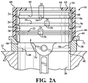
- the housing 52 can be constructed entirely of metal, e.g. stainless steel, plastic, or a combination of metal and plastic, such as shown in Figure 2A , wherein a tubular metal portion 68, e.g. stainless steel, provides the inner surface 56, and an outer plastic portion 70 forms the wall 62 and the balance of the housing 52.
- metal e.g. stainless steel, plastic, or a combination of metal and plastic, such as shown in Figure 2A , wherein a tubular metal portion 68, e.g. stainless steel, provides the inner surface 56, and an outer plastic portion 70 forms the wall 62 and the balance of the housing 52.
- the apparatus inner surface 56 is diametrically dimensioned to prevent the gaps 34 between the piston ring free ends 36 from being completely closed while the piston assembly 10 is received in the housing 52.
- the inner surface 56 is diametrically dimensioned to prevent the rings 24, 26, 28 from being dislodged or otherwise removed from the ring grooves 18, 20, 22 while the piston assembly 10 is received in the housing 52.
- the inner surface 56 provides a slight clearance fit relative to an outer surface of the rings 24, 26, 28, though the clearance does not allow the rings to be displaced sufficiently radially outwardly to be removed from the ring grooves 18, 20, 22.
- an inner surface 156 is dimensioned to have a line-to-line or slight interference fit with the outer surface of the rings 124, 126, 128, though not causing the gaps 134 to be completely closed, thereby avoiding unwanted plastic deformation of the rings 124, 126, 128, as discussed above.
- the housing 52 has a chamfered surface 72 diverging radially outwardly from the first end 58 toward the second end 60.
- the chamfered surface 72 is configured having a conical taper having an angle of inclination configured for flush or substantially flush abutment with the conical surface 46 of the cone 38. Accordingly, upon mating the respective conical surfaces 46, 72 with one another, a substantially continuous wall of material is formed that is substantially free of gaps, wherein the inner surface 56 of the housing 52 is flush or substantially flush with the upper region 50 of the cone through bore 40. It should be recognized that the inner surface 56 is no greater in diameter than the inner surface 46 of the cone 38, and can be slightly reduced in diameter, such as shown with respect to the embodiment of Figure 2B .
- the piston assembly 12 is disposed at least partially in the bore 54 of the housing 52 with the upper crown 16 of the piston head 14 facing the second end 60 of the housing 52 without completely closing the free gaps 34 of the piston rings 24, 26, 28, 124, 126, 128.
- the housing 52 in addition to protecting the piston assembly 12 from being damaged, acts to protect against the ingress of debris/contamination into the bore 54. This is facilitated by the wall 62 overlying the piston head 14, thereby closing off any potential path to the ingress of debris/contamination.
- the piston assembly 12 can now be stored and transported as desired for subsequent assembly, such as in a position shown in Figure 1 .
- the stuffing cone 38 is positioned over the cylinder bore 30 in concentric relation therewith, such the lower region 48 of the cone 38 is flush or substantially flush with the cylinder bore 30.
- the first end 58 of the housing 52 is brought into nested, conforming abutment with the upper end 44 of the stuffing cone 38, such that the respective conical surfaces 46, 72 nest with one another to align the bore 54 of the housing 52 axially relative to the bore 40 of the cone 38.
- the plunger 66 is then used to push the piston assembly 12 axially outwardly from the housing 52 through the stuffing cone 38 and into the cylinder bore 30.
- the respective piston rings 24, 26, 28, 124, 126, 128 are caused to compress radially inwardly by the cone 38 sufficiently to allow them to slide freely into the cylinder bore 30.
- the piston rings 24, 26, 28, 124, 126, 128 retain their ability to function as intended within the cylinder bore 30.
- the housing 52 can reused as desired. Accordingly, not only is the housing 52 well suited to store and transport piston assemblies, but it is also economical in use.
Landscapes
- Engineering & Computer Science (AREA)
- Mechanical Engineering (AREA)
- General Engineering & Computer Science (AREA)
- Chemical & Material Sciences (AREA)
- Combustion & Propulsion (AREA)
- Pistons, Piston Rings, And Cylinders (AREA)
- Automatic Assembly (AREA)
- Compressor (AREA)
Description
- This invention relates generally to internal combustion engine pistons, and more particularly to apparatus for transporting and installing piston assemblies.
- The transportation of a piston assembly, including a piston head with one or more piston rings and a connecting rod, comes with known problems. For example, maintaining the ring or rings within their respective grooves during transportation can be problematic, thereby resulting in lost or damaged piston rings. Thus, in an effort to prevent losing or damaging piston rings and their associated ring grooves, the piston rings can be maintained radially compressed in the ring grooves. However, a known problem of over compressing the piston rings results if the radial compression is too great. If the piston rings are overly compressed in the ring grooves, the "free gap" desired and provided between ends of the piston ring is plastically reduced, which in turn detracts from the ability of the piston ring to provide the desired expanded radial compression against a cylinder wall in use. As such, the sealing and scraping function of the piston ring is diminished.
- Further, assembling the piston assembly into a cylinder bore of an engine block is a complex process requiring the piston rings to be at least slightly compressed radially for receipt in the cylinder bore. It is known to use a compression sleeve, also referred to as stuffing cone or ring, during assembly that gradually causes the piston rings to be compressed radially inwardly along a constant tapered surface sufficiently for receipt within the cylinder bore of the engine block. Although the compression sleeve functions well to aid in assembly, the aforementioned problems remain with respect to transporting and storing piston assemblies prior to installation into an engine.
JP H06 25659 U
WO 84/03082 A - Further
US 3,707,027 A discloses a loading sleeve for installing a piston equipped with radially compressible piston rings into a cylinder bore of an engine block. The sleeve is a generally cylindrical body open at its axially opposite ends and it is tapered internally to squeeze the rings from their free state diameter down to bore diameter as the piston moves axially through the sleeve. - In accordance with one aspect of the invention, a piston assembly transportation and assembly apparatus according to claim 1, in particular configured to maintain a piston assembly in its assembled state during transportation and to aid in the installation of the piston assembly into a cylinder bore is provided. The piston assembly transportation and assembly apparatus includes a housing having a bore bounded by an inner cylindrical surface extending from a first end of the housing toward a second end of the housing. A chamfered surface diverges radially outwardly from the first end toward the second end and the second end has a wall extending radially inwardly from the inner cylindrical surface to axially confront an upper crown of the piston assembly.
- In accordance with another aspect of the invention, a piston assembly transportation and assembly apparatus according to claim 6, in particular configured to maintain a piston assembly in its assembled state during transportation and to aid in the installation of the piston assembly into a cylinder bore in combination with a stuffing cone is provided. The stuffing cone has a through bore extending between a lower end configured to abut an engine block and an upper end and having a conical surface diverging radially outwardly from the through bore toward the upper end. The piston assembly transportation and assembly apparatus includes a housing having a bore bounded by an inner cylindrical surface extending from a first end of the housing toward a second end of the housing. A chamfered surface diverges radially outwardly from the first end toward the second end and is configured to mate with the conical surface of the stuffing cone. The second end has a wall extending radially inwardly from the inner cylindrical surface to axially confront an upper crown of the piston assembly.
- In accordance with another aspect of the invention, a piston assembly transportation and assembly apparatus in combination with a piston assembly according to
claim 10 is provided. The piston assembly includes a piston head having an upper crown with at least one piston ring groove having a piston ring disposed therein. The piston ring is split to provide a gap between free ends of the piston ring. The piston assembly transportation and assembly apparatus includes a housing having a bore bounded by an inner cylindrical surface extending from a first end of the housing toward a second end of the housing. The cylindrical surface is dimensioned to prevent the gap between the piston ring free ends from being completely closed while the piston assembly is received in the housing. A chamfered surface diverges radially outwardly from the first end toward the second end and the second end has a wall extending radially inwardly from the inner cylindrical surface to axially confront an upper crown of the piston assembly. - In accordance with yet another aspect of the invention, a method of transporting and installing a piston assembly according to claim 13 is provided. The method includes providing a piston head having at least one piston ring disposed in a ring groove with the piston ring having a free gap provided between uncompressed opposite ends of the piston ring. Further, providing a housing having a bore bounded by an inner cylindrical surface extending from an upper edge of a first end of the housing toward a second end of the housing having a wall extending radially inwardly from the inner cylindrical surface. Further yet, disposing the piston head in the bore of the housing with the piston head facing the second end of the housing without completely closing the free gap of the piston ring. Then, transporting the piston assembly within the housing. Further, providing a stuffing cone having a through bore extending between a lower end configured to abut an engine block and an upper end. Then, positioning the stuffing cone over a cylinder bore of an engine block. Further yet, bringing the first end of the housing into abutment with the upper end of the stuffing cone. And, pushing the piston assembly from the housing through the stuffing cone and into the cylinder bore.
- These and other aspects, features and advantages of the present invention will become more readily appreciated when considered in connection with the following detailed description of presently preferred embodiments and best mode, appended claims and accompanying drawings, in which:
-
Figure 1 is a partial cross-sectional elevation view showing a piston assembly received in a transportation and assembly apparatus constructed in accordance with one aspect of the invention with the transportation and assembly apparatus shown in a transportation state; -
Figure 2 is an enlarged partial cross-sectional elevation view of the transportation and assembly apparatus and piston assembly shown in an initial state of assembly; -
Figure 2A is a view similar toFigure 2 of a transportation and assembly apparatus constructed in accordance with another aspect of the invention; -
Figure 2B is a view similar toFigure 2 of a transportation and assembly apparatus constructed in accordance with another aspect of the invention; and -
Figure 3 is a view similar toFigure 2 showing the piston assembly in an advanced state of assembly. - Referring in more detail to the drawings,
Figure 1 illustrates a piston assembly transportation and assembly apparatus, referred to hereafter asapparatus 10, constructed in accordance with one aspect of the invention. Theapparatus 10 provides methods of transporting and installing apiston assembly 12 therewith. Thepiston assembly 12, having a piston body, also referred to aspiston head 14, and anupper crown 16 with at least one piston ring groove, and shown here as a plurality ofpiston ring grooves respective piston rings apparatus 10 for storage, transportation, and to facilitate assembly of thepiston assembly 12 within acylinder bore 30 of an engine block 32 (Figures 2 ,2A and3 ). Theapparatus 10 provides an easy way in which to store and transport thepiston assembly 12 without damaging or otherwise impacting the functionality of thepiston rings piston assembly 12 from theapparatus 10 into thecylinder bore 30. - While storing and transporting the
piston assembly 12, it is important to avoid damaging, contaminating and otherwise impacting the ability of thepiston assembly 12 to function as intended within the cylinder bore 30. One particular aspect to avoid is causing damage to thepiston rings Figure 1 , thepiston rings gap 34 betweenfree ends 36 of thepiston rings gaps 34 have a predetermined width extending between thefree ends 36 that is intended to be maintained prior to assembly and at least in part thereafter to provide a predetermined amount of radially outwardly acting expansion spring force of therings rings compression ring 24, which seals the compression chamber from any leakage during the combustion process; awiper ring 26, which further seals the combustion chamber and wipes the wall of the cylinder bore 30 clean of any excess oil; and/or anoil seal ring 28, which also wipes excess oil from the wall of the cylinder bore 30 during reciprocation of thepiston head 14. As such, it is important that during storage and transportation of thepiston assembly 10 that thegaps 34 be maintained, thereby avoiding unwanted radially contracted plastic deformation of therings - The
apparatus 10 is intended to be used in combination with a standard compression cup, also referred to as a piston ring stuffing cone, and referred to hereafter ascone 38. Thecone 38 has an annular throughbore 40 extending between alower end 42 configured to abut a generally flat upper sealing surface of theengine block 32 and anupper end 44. Theupper end 44 has a tapered,conical surface 46 diverging radially outwardly from thethrough bore 40 toward theupper end 44. The throughbore 40 has alower region 48 immediately adjacent thelower end 42 that is sized to be the same or substantially the same diameter or slightly smaller in diameter than the cylinder bore 30 to allow therings bore 40 has an upper region that can be tapered in a slight converging manner from theconical surface 46 toward thelower region 48, thus causing therings rings - The
apparatus 10 has ahousing 52 including abore 54 bounded by a cylindricalinner surface 56 extending from afirst end 58 of thehousing 52 toward asecond end 60 of thehousing 52. Thesecond end 60 has awall 62 extending radially inwardly from the innercylindrical surface 56. Thewall 62 has a throughopening 64 formed therein to facilitate disposing thepiston assembly 12 into the cylinder bore 30 during assembly, as discussed further below. The throughopening 64 is sized to accommodate a plunger 66 (Figure 3 ) during assembly, such that the plunger 66 is free to extend through theopening 64 to push thepiston assembly 12 out of theapparatus 10, through thecone 38 and into the cylinder bore 30. Although thewall 62 includes theopening 64, thewall 62 extends sufficiently radially inwardly from theinner surface 56 to overlie an outer peripheral portion of the pistonupper crown 16, thereby confronting and preventing thepiston assembly 12 from passing through the throughopening 64. Thehousing 52 can be constructed entirely of metal, e.g. stainless steel, plastic, or a combination of metal and plastic, such as shown inFigure 2A , wherein atubular metal portion 68, e.g. stainless steel, provides theinner surface 56, and anouter plastic portion 70 forms thewall 62 and the balance of thehousing 52. - The apparatus
inner surface 56 is diametrically dimensioned to prevent thegaps 34 between the piston ring free ends 36 from being completely closed while thepiston assembly 10 is received in thehousing 52. In addition, theinner surface 56 is diametrically dimensioned to prevent therings ring grooves piston assembly 10 is received in thehousing 52. In one construction of thehousing 52, such as shown inFigure 2 , theinner surface 56 provides a slight clearance fit relative to an outer surface of therings ring grooves housing 152, wherein the same reference numerals offset by a factor of 100 are used to identify like features, aninner surface 156 is dimensioned to have a line-to-line or slight interference fit with the outer surface of therings gaps 134 to be completely closed, thereby avoiding unwanted plastic deformation of therings - The
housing 52 has a chamferedsurface 72 diverging radially outwardly from thefirst end 58 toward thesecond end 60. The chamferedsurface 72 is configured having a conical taper having an angle of inclination configured for flush or substantially flush abutment with theconical surface 46 of thecone 38. Accordingly, upon mating the respectiveconical surfaces inner surface 56 of thehousing 52 is flush or substantially flush with theupper region 50 of the cone throughbore 40. It should be recognized that theinner surface 56 is no greater in diameter than theinner surface 46 of thecone 38, and can be slightly reduced in diameter, such as shown with respect to the embodiment ofFigure 2B . - In use, the
piston assembly 12 is disposed at least partially in thebore 54 of thehousing 52 with theupper crown 16 of thepiston head 14 facing thesecond end 60 of thehousing 52 without completely closing thefree gaps 34 of the piston rings 24, 26, 28, 124, 126, 128. With thepiston assembly 12 disposed in thebore 54, thehousing 52, in addition to protecting thepiston assembly 12 from being damaged, acts to protect against the ingress of debris/contamination into thebore 54. This is facilitated by thewall 62 overlying thepiston head 14, thereby closing off any potential path to the ingress of debris/contamination. Thepiston assembly 12 can now be stored and transported as desired for subsequent assembly, such as in a position shown inFigure 1 . - During assembly, the stuffing
cone 38 is positioned over the cylinder bore 30 in concentric relation therewith, such thelower region 48 of thecone 38 is flush or substantially flush with the cylinder bore 30. - Then, the
first end 58 of thehousing 52 is brought into nested, conforming abutment with theupper end 44 of the stuffingcone 38, such that the respectiveconical surfaces bore 54 of thehousing 52 axially relative to thebore 40 of thecone 38. - Further, the plunger 66 is then used to push the
piston assembly 12 axially outwardly from thehousing 52 through the stuffingcone 38 and into the cylinder bore 30. As thepiston assembly 12 is urged into the cylinder bore 30, as shown inFigure 3 , therespective piston rings cone 38 sufficiently to allow them to slide freely into the cylinder bore 30. Given therings - Upon completing the assembly process, the
housing 52 can reused as desired. Accordingly, not only is thehousing 52 well suited to store and transport piston assemblies, but it is also economical in use. - Many modifications and variations of the present invention are possible in light of the above teachings. It is, therefore, to be understood that the invention may be practiced otherwise than as specifically described, and that the scope of the invention is defined by any ultimately allowed claims.
Claims (16)
- A piston assembly transportation and assembly apparatus (10) configured to maintain a piston assembly (12) in its assembled state during transportation and to aid in the installation of the piston assembly into a cylinder bore, comprising:a housing (52) having a bore (54) bounded by an inner cylindrical surface (56) extending from a first end (58) of said housing toward a second end (60) of said housing,a chamfered surface (72) diverging radially outwardly from said first end (58) toward said second end (60) andsaid second end (60) having a wall (62) extending radially inwardly from said inner cylindrical surface to axially confront an upper crown (16) of the piston assembly.
- The piston assembly transportation and assembly apparatus of claim 1, wherein said wall has a through opening (64) .
- The piston assembly transportation and assembly apparatus of claim 1, wherein said inner cylindrical surface (56) is configured to prevent piston rings of the piston assembly from being fully radially compressed.
- The piston assembly transportation and assembly apparatus of claim 1, wherein said chamfered surface is a conical taper.
- The piston assembly transportation and assembly apparatus of claim 1, wherein said housing has a metal tubular portion (68) forming said inner surface and an outer plastic portion forming said wall.
- A piston assembly transportation and assembly apparatus configured to maintain a piston assembly in its assembled state during transportation and to aid in the installation of the piston assembly into a cylinder bore in combination with a stuffing cone,
said stuffing cone (38) having a through bore (40) extending between a lower end configured to abut an engine block and an upper end (44) and having a conical surface (46) diverging radially outwardly from said through bore (40) toward said upper end (44),
said piston assembly transportation and assembly apparatus being the piston assembly transportation and assembly apparatus according to claim 1,
wherein the chamfered surface (72) is configured to mate with said conical surface (46) of said stuffing cone (38). - The piston assembly transportation and assembly apparatus and stuffing cone combination of claim 6, wherein said inner cylindrical surface of said piston assembly transportation and assembly apparatus is dimensioned to prevent piston rings of the piston assembly from being fully radially compressed.
- The piston assembly transportation and assembly apparatus and stuffing cone combination of claim 6, wherein said chamfered surface (72) is a conical taper having an angle configured for substantially flush abutment with said conical surface of said stuffing cone.
- The piston assembly transportation and assembly apparatus and stuffing cone combination of claim 6, wherein said housing has a metal tubular portion (68) forming said inner surface and an outer plastic portion forming said wall.
- A piston assembly transportation and assembly apparatus in combination with a piston assembly including a piston head (14) having an upper crown (16) with at least one piston ring groove (18, 20, 22) having a piston ring (24, 26, 28) disposed therein, said piston ring being split to provide a gap (34) between free ends of the piston ring,
said piston assembly transportation and assembly apparatus being the piston assembly transportation and assembly apparatus according to claim 1,
wherein the cylindrical surface (56) is dimensioned to prevent said gap (34) between said piston ring free ends from being completely closed while said piston assembly is received in said housing. - The piston assembly transportation and assembly apparatus and piston assembly of claim 10, wherein said wall has a through opening (64).
- The piston assembly transportation and assembly apparatus and piston assembly of claim 10, wherein said housing has a metal tubular portion (68) forming said inner surface and an outer plastic portion forming said wall.
- A method of transporting and installing a piston assembly, comprising:providing a piston head (14) having at least one piston ring (24, 26, 28) disposed in a ring groove (18, 20, 22) with the piston ring having a free gap (34) provided between uncompressed opposite ends of the piston ring;providing a housing (52) having a bore (54) bounded by an inner cylindrical surface (56) extending from an upper edge of a first end (58) of the housing toward a second end (60) of the housing having a wall extending radially inwardly from the inner cylindrical surface;disposing the piston head (14) in the bore (54) of the housing with the piston head facing the second end of the housing without completely closing the free gap of the piston ring;transporting the piston assembly within the housing;providing a stuffing cone (38) having a through bore (40) extending between a lower end configured to abut an engine block and an upper end;positioning the stuffing cone over a cylinder bore (30) of an engine block;bringing the first end (58) of the housing into abutment with the upper end of the stuffing block; andpushing the piston assembly from the housing through the stuffing cone and into the cylinder bore (30),further includingproviding the first end (58) of the housing with a chamfered surface (72) diverging radially outwardly from the first end (58) to the second end (60), and the upper end (44) of the stuffing cone with a conical surface (46) diverging radially outwardly form the through bore (40) toward the upper end (44), and bringing the chamfered surface (72) and the conical surface (46) into conforming abutment with one another.
- The method of claim 13 further including providing a circumferential clearance fit between the piston ring and the inner cylindrical surface of the housing.
- The method of claim 14, further including extending the piston ring into the ring groove over a circumferentially extending depth that is greater than the circumferential clearance fit to prevent the piston ring from coming out of the ring groove while the piston assembly is in the bore.
- The method of claim 13, further including reusing the housing for subsequent storage, transportation and installation of a piston assembly into a cylinder bore.
Applications Claiming Priority (2)
| Application Number | Priority Date | Filing Date | Title |
|---|---|---|---|
| US12/849,097 US8640314B2 (en) | 2010-08-03 | 2010-08-03 | Piston assembly transportation and installation apparatus and methods of transporting and installing a piston assembly therewith |
| PCT/US2011/046192 WO2012018760A1 (en) | 2010-08-03 | 2011-08-02 | Piston assembly transportation and installation apparatus and methods of transporting and installing a piston assembly therewith |
Publications (2)
| Publication Number | Publication Date |
|---|---|
| EP2601011A1 EP2601011A1 (en) | 2013-06-12 |
| EP2601011B1 true EP2601011B1 (en) | 2018-09-19 |
Family
ID=44630337
Family Applications (1)
| Application Number | Title | Priority Date | Filing Date |
|---|---|---|---|
| EP11743918.2A Not-in-force EP2601011B1 (en) | 2010-08-03 | 2011-08-02 | Piston assembly transportation and installation apparatus and methods of transporting and installing a piston assembly therewith |
Country Status (7)
| Country | Link |
|---|---|
| US (2) | US8640314B2 (en) |
| EP (1) | EP2601011B1 (en) |
| JP (1) | JP2013534288A (en) |
| KR (1) | KR101955635B1 (en) |
| CN (1) | CN103079755B (en) |
| BR (1) | BR112013002565A2 (en) |
| WO (1) | WO2012018760A1 (en) |
Families Citing this family (10)
| Publication number | Priority date | Publication date | Assignee | Title |
|---|---|---|---|---|
| JP6252063B2 (en) * | 2013-09-19 | 2017-12-27 | 三菱自動車工業株式会社 | Piston equipped with a piston ring and method of manufacturing an engine incorporating the piston |
| US10279443B2 (en) | 2014-06-02 | 2019-05-07 | Reel Power Licensing Corp. | Accumulator assembly fixture |
| CN106256755B (en) * | 2015-06-19 | 2018-08-31 | 强哲菲 | Transhipment fork truck and Piston Machining production line for Piston Machining production line |
| JP6603284B2 (en) * | 2017-10-05 | 2019-11-06 | 株式会社リケン | side rail |
| US10989306B2 (en) | 2018-03-28 | 2021-04-27 | Graco Minnesota Inc. | Packing stack carrier for paint and other fluid pumps |
| US11458605B2 (en) | 2018-03-28 | 2022-10-04 | Graco Minnesota Inc. | Packing insertion tool for paint and other fluid pumps |
| WO2019221698A1 (en) * | 2018-05-14 | 2019-11-21 | Reel Power Licensing Corp. | Accumulator assembly fixture |
| KR102121120B1 (en) * | 2018-10-19 | 2020-06-10 | 한국기초과학지원연구원 | Device for measuring thermal diffusivity of a sample |
| US12269148B2 (en) | 2019-08-16 | 2025-04-08 | Cummins Inc. | Piston ring installation tool |
| US11326694B2 (en) * | 2019-12-17 | 2022-05-10 | Acd, Llc | Cryogenic piston ring improvement |
Family Cites Families (24)
| Publication number | Priority date | Publication date | Assignee | Title |
|---|---|---|---|---|
| DE125537C (en) | ||||
| US1593220A (en) * | 1924-08-20 | 1926-07-20 | Henry C Phelps | Piston-ring compressor |
| US1572801A (en) | 1925-02-05 | 1926-02-09 | Kearney Paul Cecil | Piston-ring compressor |
| US2697870A (en) | 1950-05-23 | 1954-12-28 | Gottlieb F Zucker | Piston inserting tool |
| US3561091A (en) | 1968-04-19 | 1971-02-09 | Leo Pigozzi | Method and apparatus for compressing piston rings and installing pistons in cylinder bores |
| US3707027A (en) | 1970-11-12 | 1972-12-26 | Sealed Power Corp | Loading sleeve for installing a piston and ring assembly into a cylinder bore |
| US3754312A (en) | 1971-10-27 | 1973-08-28 | F Komorek | Ring compressor |
| CH652174A5 (en) * | 1981-02-27 | 1985-10-31 | Leduc Rene Hydro Sa | OLEO-PNEUMATIC ACCUMULATOR AND METHOD FOR MANUFACTURING THE ACCUMULATOR. |
| JPS59115129A (en) | 1982-12-22 | 1984-07-03 | Honda Motor Co Ltd | How to assemble the piston |
| GB8303753D0 (en) | 1983-02-10 | 1983-03-16 | Ae Plc | Piston and assemblies |
| US4480368A (en) | 1983-05-02 | 1984-11-06 | Caterpillar Tractor Co. | Unitary installation of engine cylinder liner, piston and rod |
| US4594760A (en) | 1985-03-18 | 1986-06-17 | Caterpillar Tractor Co. | Apparatus for and method of packaging and inserting an engine cylinder assembly into an engine block |
| US4971846A (en) * | 1987-11-16 | 1990-11-20 | Tre Corporation | Thermoplastic cylinder and process for manufacturing same |
| JPH082449Y2 (en) * | 1988-05-12 | 1996-01-29 | 日産自動車株式会社 | Piston insertion jig for integrated cylinder block |
| CA2041269A1 (en) * | 1990-05-04 | 1991-11-05 | Wayne F. Wehber | Piston assembly |
| JP2589513Y2 (en) | 1992-08-31 | 1999-01-27 | いすゞ自動車株式会社 | Jig for assembling pistons for reciprocating engines |
| CN1115355A (en) * | 1994-07-19 | 1996-01-24 | 张向平 | Engine piston assembly |
| CN2260173Y (en) * | 1996-02-14 | 1997-08-20 | 王保东 | Piston element with automatic lubricating and clearance adjusting device |
| DE19912166C2 (en) | 1999-03-18 | 2001-05-31 | Federal Mogul Burscheid Gmbh | Assembly tool for assembling pistons with radially outward-tensioning piston rings in cylinders |
| US6318551B1 (en) | 1999-11-10 | 2001-11-20 | Caterpillar Inc. | Method and apparatus for installing a prepackaged piston assembly in an engine |
| US6516511B1 (en) | 2000-06-29 | 2003-02-11 | Caterpillar Inc | Position sensor for piston ring compressor |
| US6389667B1 (en) | 2000-06-29 | 2002-05-21 | Caterpillar Inc. | Piston ring compressor |
| US6634386B1 (en) * | 2001-10-02 | 2003-10-21 | Kelsey-Hayes Company | Fluid accumulator for use in a vehicle anti-lock brake system |
| JP2003172301A (en) * | 2001-12-04 | 2003-06-20 | Nhk Spring Co Ltd | accumulator |
-
2010
- 2010-08-03 US US12/849,097 patent/US8640314B2/en not_active Expired - Fee Related
-
2011
- 2011-08-02 JP JP2013523257A patent/JP2013534288A/en active Pending
- 2011-08-02 CN CN201180041471.1A patent/CN103079755B/en not_active Expired - Fee Related
- 2011-08-02 WO PCT/US2011/046192 patent/WO2012018760A1/en not_active Ceased
- 2011-08-02 EP EP11743918.2A patent/EP2601011B1/en not_active Not-in-force
- 2011-08-02 BR BR112013002565-4A patent/BR112013002565A2/en not_active Application Discontinuation
- 2011-08-02 KR KR1020137005283A patent/KR101955635B1/en not_active Expired - Fee Related
-
2014
- 2014-01-27 US US14/164,535 patent/US9297421B2/en active Active
Non-Patent Citations (1)
| Title |
|---|
| None * |
Also Published As
| Publication number | Publication date |
|---|---|
| EP2601011A1 (en) | 2013-06-12 |
| KR20130136973A (en) | 2013-12-13 |
| US9297421B2 (en) | 2016-03-29 |
| BR112013002565A2 (en) | 2020-09-08 |
| US20140137387A1 (en) | 2014-05-22 |
| JP2013534288A (en) | 2013-09-02 |
| CN103079755B (en) | 2015-09-23 |
| CN103079755A (en) | 2013-05-01 |
| WO2012018760A1 (en) | 2012-02-09 |
| US8640314B2 (en) | 2014-02-04 |
| KR101955635B1 (en) | 2019-03-07 |
| US20120031803A1 (en) | 2012-02-09 |
Similar Documents
| Publication | Publication Date | Title |
|---|---|---|
| US9297421B2 (en) | Piston assembly transportation and installation apparatus and methods of transporting and installing a piston assembly therewith | |
| EP1818562B1 (en) | Gas spring | |
| EP3392533B1 (en) | Sealing device | |
| US20030173746A1 (en) | Installation and deployment sleeves for lip seals | |
| US8444122B2 (en) | Gas spring with guide | |
| WO2011071967A3 (en) | Compound sealing mechanism, cylinder liner, and engine assembly method | |
| US20180087595A1 (en) | Overtravel relief assembly for a gas spring | |
| JP2013002443A (en) | Insert for engine cylinder | |
| US10514101B2 (en) | Low load seal with outer diameter flap | |
| US20160290161A1 (en) | Device for centring and guiding the rotation of a turbine engine shaft including improved means for retaining the external bearing ring | |
| US8112887B2 (en) | Two-piece shipping cap for a seal | |
| JP2005249200A (en) | Two-piece valve shaft seal | |
| US11686338B2 (en) | Blind rivet insert, a component with an installed blind rivet insert and method for installing such a blind rivet insert in a component opening | |
| CA2924575C (en) | Dual pre-load cylindrical seal | |
| CN103619678A (en) | Master cylinder assembly in brake system | |
| EP3623669B1 (en) | Mechanical seal | |
| CN110088429B (en) | Method for installing a camshaft in a bearing shell and a camshaft | |
| CN100363655C (en) | Lip-shaped sealing cylinder | |
| US20040092320A1 (en) | Slip seal retainer and stop | |
| JP4853633B2 (en) | Sealing device | |
| JPH07133866A (en) | Cylinder device | |
| US20240082965A1 (en) | Piston ring installation jig and piston ring installation method using the jig | |
| JP2527908Y2 (en) | Sampling jig | |
| US20240401700A1 (en) | Spring-loaded gland wall seal carrier for reverse acting differential pressure | |
| CN103711901B (en) | Multi-part piston |
Legal Events
| Date | Code | Title | Description |
|---|---|---|---|
| PUAI | Public reference made under article 153(3) epc to a published international application that has entered the european phase |
Free format text: ORIGINAL CODE: 0009012 |
|
| 17P | Request for examination filed |
Effective date: 20130213 |
|
| AK | Designated contracting states |
Kind code of ref document: A1 Designated state(s): AL AT BE BG CH CY CZ DE DK EE ES FI FR GB GR HR HU IE IS IT LI LT LU LV MC MK MT NL NO PL PT RO RS SE SI SK SM TR |
|
| DAX | Request for extension of the european patent (deleted) | ||
| STAA | Information on the status of an ep patent application or granted ep patent |
Free format text: STATUS: EXAMINATION IS IN PROGRESS |
|
| 17Q | First examination report despatched |
Effective date: 20171109 |
|
| REG | Reference to a national code |
Ref country code: DE Ref legal event code: R079 Ref document number: 602011052172 Country of ref document: DE Free format text: PREVIOUS MAIN CLASS: B23P0019040000 Ipc: F16C0035067000 |
|
| RIC1 | Information provided on ipc code assigned before grant |
Ipc: F16C 35/067 20060101AFI20180405BHEP Ipc: B25B 27/12 20060101ALI20180405BHEP Ipc: F16J 9/10 20060101ALI20180405BHEP Ipc: B23P 19/04 20060101ALI20180405BHEP |
|
| GRAP | Despatch of communication of intention to grant a patent |
Free format text: ORIGINAL CODE: EPIDOSNIGR1 |
|
| STAA | Information on the status of an ep patent application or granted ep patent |
Free format text: STATUS: GRANT OF PATENT IS INTENDED |
|
| INTG | Intention to grant announced |
Effective date: 20180514 |
|
| RAP1 | Party data changed (applicant data changed or rights of an application transferred) |
Owner name: FEDERAL-MOGUL LLC |
|
| GRAS | Grant fee paid |
Free format text: ORIGINAL CODE: EPIDOSNIGR3 |
|
| GRAA | (expected) grant |
Free format text: ORIGINAL CODE: 0009210 |
|
| STAA | Information on the status of an ep patent application or granted ep patent |
Free format text: STATUS: THE PATENT HAS BEEN GRANTED |
|
| AK | Designated contracting states |
Kind code of ref document: B1 Designated state(s): AL AT BE BG CH CY CZ DE DK EE ES FI FR GB GR HR HU IE IS IT LI LT LU LV MC MK MT NL NO PL PT RO RS SE SI SK SM TR |
|
| REG | Reference to a national code |
Ref country code: GB Ref legal event code: FG4D |
|
| REG | Reference to a national code |
Ref country code: CH Ref legal event code: EP |
|
| REG | Reference to a national code |
Ref country code: AT Ref legal event code: REF Ref document number: 1043597 Country of ref document: AT Kind code of ref document: T Effective date: 20181015 |
|
| REG | Reference to a national code |
Ref country code: IE Ref legal event code: FG4D |
|
| REG | Reference to a national code |
Ref country code: DE Ref legal event code: R096 Ref document number: 602011052172 Country of ref document: DE |
|
| REG | Reference to a national code |
Ref country code: NL Ref legal event code: MP Effective date: 20180919 |
|
| PG25 | Lapsed in a contracting state [announced via postgrant information from national office to epo] |
Ref country code: LT Free format text: LAPSE BECAUSE OF FAILURE TO SUBMIT A TRANSLATION OF THE DESCRIPTION OR TO PAY THE FEE WITHIN THE PRESCRIBED TIME-LIMIT Effective date: 20180919 Ref country code: SE Free format text: LAPSE BECAUSE OF FAILURE TO SUBMIT A TRANSLATION OF THE DESCRIPTION OR TO PAY THE FEE WITHIN THE PRESCRIBED TIME-LIMIT Effective date: 20180919 Ref country code: BG Free format text: LAPSE BECAUSE OF FAILURE TO SUBMIT A TRANSLATION OF THE DESCRIPTION OR TO PAY THE FEE WITHIN THE PRESCRIBED TIME-LIMIT Effective date: 20181219 Ref country code: GR Free format text: LAPSE BECAUSE OF FAILURE TO SUBMIT A TRANSLATION OF THE DESCRIPTION OR TO PAY THE FEE WITHIN THE PRESCRIBED TIME-LIMIT Effective date: 20181220 Ref country code: NO Free format text: LAPSE BECAUSE OF FAILURE TO SUBMIT A TRANSLATION OF THE DESCRIPTION OR TO PAY THE FEE WITHIN THE PRESCRIBED TIME-LIMIT Effective date: 20181219 Ref country code: FI Free format text: LAPSE BECAUSE OF FAILURE TO SUBMIT A TRANSLATION OF THE DESCRIPTION OR TO PAY THE FEE WITHIN THE PRESCRIBED TIME-LIMIT Effective date: 20180919 Ref country code: RS Free format text: LAPSE BECAUSE OF FAILURE TO SUBMIT A TRANSLATION OF THE DESCRIPTION OR TO PAY THE FEE WITHIN THE PRESCRIBED TIME-LIMIT Effective date: 20180919 |
|
| REG | Reference to a national code |
Ref country code: LT Ref legal event code: MG4D |
|
| PG25 | Lapsed in a contracting state [announced via postgrant information from national office to epo] |
Ref country code: HR Free format text: LAPSE BECAUSE OF FAILURE TO SUBMIT A TRANSLATION OF THE DESCRIPTION OR TO PAY THE FEE WITHIN THE PRESCRIBED TIME-LIMIT Effective date: 20180919 Ref country code: LV Free format text: LAPSE BECAUSE OF FAILURE TO SUBMIT A TRANSLATION OF THE DESCRIPTION OR TO PAY THE FEE WITHIN THE PRESCRIBED TIME-LIMIT Effective date: 20180919 Ref country code: AL Free format text: LAPSE BECAUSE OF FAILURE TO SUBMIT A TRANSLATION OF THE DESCRIPTION OR TO PAY THE FEE WITHIN THE PRESCRIBED TIME-LIMIT Effective date: 20180919 |
|
| REG | Reference to a national code |
Ref country code: AT Ref legal event code: MK05 Ref document number: 1043597 Country of ref document: AT Kind code of ref document: T Effective date: 20180919 |
|
| PG25 | Lapsed in a contracting state [announced via postgrant information from national office to epo] |
Ref country code: CZ Free format text: LAPSE BECAUSE OF FAILURE TO SUBMIT A TRANSLATION OF THE DESCRIPTION OR TO PAY THE FEE WITHIN THE PRESCRIBED TIME-LIMIT Effective date: 20180919 Ref country code: RO Free format text: LAPSE BECAUSE OF FAILURE TO SUBMIT A TRANSLATION OF THE DESCRIPTION OR TO PAY THE FEE WITHIN THE PRESCRIBED TIME-LIMIT Effective date: 20180919 Ref country code: EE Free format text: LAPSE BECAUSE OF FAILURE TO SUBMIT A TRANSLATION OF THE DESCRIPTION OR TO PAY THE FEE WITHIN THE PRESCRIBED TIME-LIMIT Effective date: 20180919 Ref country code: AT Free format text: LAPSE BECAUSE OF FAILURE TO SUBMIT A TRANSLATION OF THE DESCRIPTION OR TO PAY THE FEE WITHIN THE PRESCRIBED TIME-LIMIT Effective date: 20180919 Ref country code: NL Free format text: LAPSE BECAUSE OF FAILURE TO SUBMIT A TRANSLATION OF THE DESCRIPTION OR TO PAY THE FEE WITHIN THE PRESCRIBED TIME-LIMIT Effective date: 20180919 Ref country code: ES Free format text: LAPSE BECAUSE OF FAILURE TO SUBMIT A TRANSLATION OF THE DESCRIPTION OR TO PAY THE FEE WITHIN THE PRESCRIBED TIME-LIMIT Effective date: 20180919 Ref country code: PL Free format text: LAPSE BECAUSE OF FAILURE TO SUBMIT A TRANSLATION OF THE DESCRIPTION OR TO PAY THE FEE WITHIN THE PRESCRIBED TIME-LIMIT Effective date: 20180919 Ref country code: IS Free format text: LAPSE BECAUSE OF FAILURE TO SUBMIT A TRANSLATION OF THE DESCRIPTION OR TO PAY THE FEE WITHIN THE PRESCRIBED TIME-LIMIT Effective date: 20190119 |
|
| PG25 | Lapsed in a contracting state [announced via postgrant information from national office to epo] |
Ref country code: PT Free format text: LAPSE BECAUSE OF FAILURE TO SUBMIT A TRANSLATION OF THE DESCRIPTION OR TO PAY THE FEE WITHIN THE PRESCRIBED TIME-LIMIT Effective date: 20190119 Ref country code: SM Free format text: LAPSE BECAUSE OF FAILURE TO SUBMIT A TRANSLATION OF THE DESCRIPTION OR TO PAY THE FEE WITHIN THE PRESCRIBED TIME-LIMIT Effective date: 20180919 Ref country code: SK Free format text: LAPSE BECAUSE OF FAILURE TO SUBMIT A TRANSLATION OF THE DESCRIPTION OR TO PAY THE FEE WITHIN THE PRESCRIBED TIME-LIMIT Effective date: 20180919 |
|
| REG | Reference to a national code |
Ref country code: DE Ref legal event code: R097 Ref document number: 602011052172 Country of ref document: DE |
|
| PLBE | No opposition filed within time limit |
Free format text: ORIGINAL CODE: 0009261 |
|
| STAA | Information on the status of an ep patent application or granted ep patent |
Free format text: STATUS: NO OPPOSITION FILED WITHIN TIME LIMIT |
|
| PG25 | Lapsed in a contracting state [announced via postgrant information from national office to epo] |
Ref country code: DK Free format text: LAPSE BECAUSE OF FAILURE TO SUBMIT A TRANSLATION OF THE DESCRIPTION OR TO PAY THE FEE WITHIN THE PRESCRIBED TIME-LIMIT Effective date: 20180919 |
|
| 26N | No opposition filed |
Effective date: 20190620 |
|
| PG25 | Lapsed in a contracting state [announced via postgrant information from national office to epo] |
Ref country code: SI Free format text: LAPSE BECAUSE OF FAILURE TO SUBMIT A TRANSLATION OF THE DESCRIPTION OR TO PAY THE FEE WITHIN THE PRESCRIBED TIME-LIMIT Effective date: 20180919 |
|
| PG25 | Lapsed in a contracting state [announced via postgrant information from national office to epo] |
Ref country code: TR Free format text: LAPSE BECAUSE OF FAILURE TO SUBMIT A TRANSLATION OF THE DESCRIPTION OR TO PAY THE FEE WITHIN THE PRESCRIBED TIME-LIMIT Effective date: 20180919 |
|
| GBPC | Gb: european patent ceased through non-payment of renewal fee |
Effective date: 20190802 |
|
| PG25 | Lapsed in a contracting state [announced via postgrant information from national office to epo] |
Ref country code: LU Free format text: LAPSE BECAUSE OF NON-PAYMENT OF DUE FEES Effective date: 20190802 Ref country code: LI Free format text: LAPSE BECAUSE OF NON-PAYMENT OF DUE FEES Effective date: 20190831 Ref country code: MC Free format text: LAPSE BECAUSE OF FAILURE TO SUBMIT A TRANSLATION OF THE DESCRIPTION OR TO PAY THE FEE WITHIN THE PRESCRIBED TIME-LIMIT Effective date: 20180919 Ref country code: CH Free format text: LAPSE BECAUSE OF NON-PAYMENT OF DUE FEES Effective date: 20190831 |
|
| REG | Reference to a national code |
Ref country code: BE Ref legal event code: MM Effective date: 20190831 |
|
| PG25 | Lapsed in a contracting state [announced via postgrant information from national office to epo] |
Ref country code: IE Free format text: LAPSE BECAUSE OF NON-PAYMENT OF DUE FEES Effective date: 20190802 |
|
| PG25 | Lapsed in a contracting state [announced via postgrant information from national office to epo] |
Ref country code: GB Free format text: LAPSE BECAUSE OF NON-PAYMENT OF DUE FEES Effective date: 20190802 Ref country code: BE Free format text: LAPSE BECAUSE OF NON-PAYMENT OF DUE FEES Effective date: 20190831 |
|
| PGFP | Annual fee paid to national office [announced via postgrant information from national office to epo] |
Ref country code: IT Payment date: 20200818 Year of fee payment: 10 |
|
| PG25 | Lapsed in a contracting state [announced via postgrant information from national office to epo] |
Ref country code: CY Free format text: LAPSE BECAUSE OF FAILURE TO SUBMIT A TRANSLATION OF THE DESCRIPTION OR TO PAY THE FEE WITHIN THE PRESCRIBED TIME-LIMIT Effective date: 20180919 |
|
| PG25 | Lapsed in a contracting state [announced via postgrant information from national office to epo] |
Ref country code: MT Free format text: LAPSE BECAUSE OF FAILURE TO SUBMIT A TRANSLATION OF THE DESCRIPTION OR TO PAY THE FEE WITHIN THE PRESCRIBED TIME-LIMIT Effective date: 20180919 Ref country code: HU Free format text: LAPSE BECAUSE OF FAILURE TO SUBMIT A TRANSLATION OF THE DESCRIPTION OR TO PAY THE FEE WITHIN THE PRESCRIBED TIME-LIMIT; INVALID AB INITIO Effective date: 20110802 |
|
| PGFP | Annual fee paid to national office [announced via postgrant information from national office to epo] |
Ref country code: FR Payment date: 20210728 Year of fee payment: 11 |
|
| PGFP | Annual fee paid to national office [announced via postgrant information from national office to epo] |
Ref country code: DE Payment date: 20210713 Year of fee payment: 11 |
|
| PG25 | Lapsed in a contracting state [announced via postgrant information from national office to epo] |
Ref country code: MK Free format text: LAPSE BECAUSE OF FAILURE TO SUBMIT A TRANSLATION OF THE DESCRIPTION OR TO PAY THE FEE WITHIN THE PRESCRIBED TIME-LIMIT Effective date: 20180919 |
|
| PG25 | Lapsed in a contracting state [announced via postgrant information from national office to epo] |
Ref country code: IT Free format text: LAPSE BECAUSE OF NON-PAYMENT OF DUE FEES Effective date: 20210802 |
|
| REG | Reference to a national code |
Ref country code: DE Ref legal event code: R119 Ref document number: 602011052172 Country of ref document: DE |
|
| P01 | Opt-out of the competence of the unified patent court (upc) registered |
Effective date: 20230528 |
|
| PG25 | Lapsed in a contracting state [announced via postgrant information from national office to epo] |
Ref country code: FR Free format text: LAPSE BECAUSE OF NON-PAYMENT OF DUE FEES Effective date: 20220831 Ref country code: DE Free format text: LAPSE BECAUSE OF NON-PAYMENT OF DUE FEES Effective date: 20230301 |