EP2600848B1 - Implantable drug delivery devices for genitourinary sites - Google Patents
Implantable drug delivery devices for genitourinary sites Download PDFInfo
- Publication number
- EP2600848B1 EP2600848B1 EP11815265.1A EP11815265A EP2600848B1 EP 2600848 B1 EP2600848 B1 EP 2600848B1 EP 11815265 A EP11815265 A EP 11815265A EP 2600848 B1 EP2600848 B1 EP 2600848B1
- Authority
- EP
- European Patent Office
- Prior art keywords
- drug
- shape
- drug delivery
- implantable
- bladder
- Prior art date
- Legal status (The legal status is an assumption and is not a legal conclusion. Google has not performed a legal analysis and makes no representation as to the accuracy of the status listed.)
- Active
Links
Images


Classifications
-
- A—HUMAN NECESSITIES
- A61—MEDICAL OR VETERINARY SCIENCE; HYGIENE
- A61M—DEVICES FOR INTRODUCING MEDIA INTO, OR ONTO, THE BODY; DEVICES FOR TRANSDUCING BODY MEDIA OR FOR TAKING MEDIA FROM THE BODY; DEVICES FOR PRODUCING OR ENDING SLEEP OR STUPOR
- A61M31/00—Devices for introducing or retaining media, e.g. remedies, in cavities of the body
- A61M31/002—Devices for releasing a drug at a continuous and controlled rate for a prolonged period of time
-
- A—HUMAN NECESSITIES
- A61—MEDICAL OR VETERINARY SCIENCE; HYGIENE
- A61M—DEVICES FOR INTRODUCING MEDIA INTO, OR ONTO, THE BODY; DEVICES FOR TRANSDUCING BODY MEDIA OR FOR TAKING MEDIA FROM THE BODY; DEVICES FOR PRODUCING OR ENDING SLEEP OR STUPOR
- A61M2210/00—Anatomical parts of the body
- A61M2210/10—Trunk
- A61M2210/1078—Urinary tract
- A61M2210/1085—Bladder
Definitions
- the present disclosure generally relates to implantable medical devices, and more particularly relates to implantable devices for controlled drug delivery to the bladder and other genitourinary sites.
- Implantable medical devices for drug delivery within the bladder or other body cavities are known from US 2009/0149833 A1 and WO 99/24106 A1 .
- the devices Preferably provide controlled release of one or more drugs for an extended period following implantation.
- Implantable drug delivery devices according to claims 1, 4, and 6 are provided in addition, further advantageous embodiments follow from the dependent claims. These implantable drug delivery devices provide a device deployable through a natural orifice and/or lumen of the body into a body cavity, such as through the urethra into the bladder, and that can be retained in the body under expected conditions, such as within the bladder during urination, during a period of controlled release of one or more drugs.
- implantable devices that can be deployed through a natural orifice or lumen of the body into a body cavity and can be retained in the body cavity once implanted.
- the devices can deliver drug locally to the implantation site or regionally once implanted.
- implantation site generally refers to a site within the body of a human patient or other animal.
- the implantation site can be any genitourinary site, such as the bladder, urethra, ureters, kidneys, prostate, seminal vesicles, ejaculatory duct, vas deferens, vagina, uterus, fallopian tubes, ovaries or any other location within a urological or reproductive system of the body, among other locations.
- the implantation site is the bladder.
- Devices for the bladder can be deployed through the urethra into the bladder in a minimally invasive deployment procedure.
- the devices may be deployed through a deployment instrument, such as a catheter or cystoscope, that extends through the urethra to the bladder.
- a deployment instrument such as a catheter or cystoscope
- the devices overcome the forces of urination to remain in the bladder, permitting drug delivery. Sustained and continuous delivery of an effective quantity of drug over an extended period may be enabled.
- the devices build upon those described in the following U.S. patent applications: U.S. Application No. 11/463,956, filed August 11, 2006 ; U.S. Application No. 12/333,182, filed December 11, 2008 ; U.S. Application No. 12/538,580, filed August 10, 2009 ; U.S. Application No. 12/825,215, filed June 28, 2010 ; U.S. Application No. 12/825,238, filed June 28, 2010 ; and U.S. Provisional Application No. 61/241,277,
- Embodiments of devices disclosed herein generally have at least one drug component.
- the drug component may include a drug and a drug reservoir.
- the drug may be in solid, semi-solid, or liquid form, and the drug reservoir may be a tube or other hollow structure that houses the drug.
- the drug reservoir may at least partially shield the drug from direct exposure to the implantation environment and may at least partially control release of the drug into the implantation environment.
- the drug component also may be a solid drug form designed for extended release in response to direct exposure to the implantation environment. That is, the drug may be in a solid form that can be operably associated with a retention structure to provide controlled release of the therapeutic or prophylactic agent, without having a separate housing structure.
- a therapeutic agent may be combined with (e.g., dispersed within) a matrix material in solid form and/or may have a controlled release coating thereon.
- the drug may be in the form of, for instance, a solid bead or disk that can be affixed to a retention structure.
- the devices generally have a deployment shape suited for deployment through a deployment instrument placed in the urethra or another natural lumen of the body.
- the deployment shape may be relatively elongated or linear.
- the device may have a reduced width with reference to its length when in the deployment shape.
- the deployment shape facilitates deployment into the body, the deployment shape may increase the likelihood of excretion of the device from the body once implanted, such as during urination. Therefore, the devices are further configured for retention in the body.
- Some device embodiments are retained in the body by assuming a retention shape.
- the device in the retention shape occupies a larger area or volume than the device in the deployment shape, reducing the likelihood of excretion while permitting the device to free-float in the bladder.
- Other examples of devices are retained in the body by anchoring to a portion of the body, such as to the bladder wall. Anchoring prevents the device from free floating in the bladder, retaining the device in the bladder with reduced likelihood of excretion.
- the device is associated with at least one retention structure.
- the retention structure may retain the device in the retention shape, or the retention structure may anchor the device to the body. Combinations of both retention modes are possible.
- Example retention structures include a string, wire, thread, cord, or other filament; a web, film, sheet, or other membrane; a balloon, basket, sponge, or other projection; two magnets, a hook and eye, a screw and threaded opening, or other fastener or lock; or a tether, screw, or other anchor, among others or combinations thereof.
- the retention structure may cause the drug component to achieve the retention shape or the retention structure itself may achieve the retention shape, either with or without changing the shape of the drug component.
- the retention structure may cause the device to automatically assume the retention shape once implanted, or the retention structure may be manipulated or manually adjusted after implantation to cause the device to assume the retention shape, such as with a medical instrument.
- the shape of the retention structure, the position of the retention structure with reference to the drug component, or both, may be altered to cause the device to assume the retention shape, and the retention structure may remain in the altered shape or position either naturally or under the influence of a fastener or lock.
- the retention structure may have a memorized shape that is spontaneously assumed upon implantation, such as in response to the temperature within or upon contact with urine in the bladder or in response to the removal of the confining force of the deployment instrument from the device upon escaping from the deployment instrument.
- a filament that can be deformed into an elongated shape for deployment and returns to a curved or coiled shape upon implantation
- a membrane that can be rolled or folded into an elongated shape for deployment and returns to an expanded shape upon implantation
- a sponge that can be compressed into reduced space for deployment and expands upon exiting the deployment instrument into the bladder or upon contacting fluid therein.
- the retention structure also may be manipulated or manually adjusted once the device is implanted to cause the device to assume the retention shape.
- Examples include a cord associated with the drug component that can be pulled to cause the drug component to change shape, a cord associated with multiple drug components that can be pulled to alter the position of the drug components with reference to each other, a filament or other structure that can be deformed into an expanded shape and maintains the shape once imparted, a balloon that can be filled, or a braided sleeve that can be expanded.
- Some device examples are associated with an anchor structure that can anchor the device in the body, such as a movable tab, a threaded fastener, or a tether, among others.
- the anchor structure may attach the device to the bladder wall so that the device is retained therein.
- FIG. 1 illustrates an implantable drug delivery device 100, wherein the drug component includes a drug reservoir 102 loaded with drug 112 and the retention structure includes two filaments 120, 122 associated with a fastener 130.
- the drug reservoir 102 is an elongated tube that can be deformed between a relatively linear deployment shape, such as the shape shown in FIG. 1A , and a relatively circular retention shape, such as the shape shown in FIG. 1B .
- the drug 112 may be loaded in the tube in a flexible form, so that the drug reservoir 102 can be moved between the two shapes.
- the drug 112 may be a number of solid drug tablets, a liquid, or a gel.
- the filaments 120, 122 may be attached to opposite ends of the drug reservoir 102 and joined by the fastener 130.
- the fastener 130 can be adjusted to adjust the position of one filament 120 with reference to the other 122, thereby adjusting the position of one end of the drug reservoir 102 with reference to the other end.
- the device 100 can assume the retention shape by adjusting the filaments 120, 122 to draw the ends of the drug reservoir 102 closer together, and thereafter the device 100 can be retained in the retention shape by preventing adjustment of the filaments 120, 122 with the fastener 130.
- the device 100 is manually adjusted into the retention shape by manually adjusting the filaments 120, 122 after the device 100 is implanted.
- the fastener 130 is a cinch nut that permits shortening the portion of the filaments 120, 122 between the drug reservoir ends and the cinch nut, but prevents lengthening of these portions of the filaments 120, 122.
- the ends of the drug reservoir 102 can be drawn closer together by pulling one or both of the filaments 120, 122 through the cinch nut, causing the device 100 to assume the retention shape.
- the cinch nut prevents lengthening of the filaments 120, 122, retaining the device in the retention shape.
- one or both of the filaments 120, 122 may be snipped, causing the drug reservoir 102 to return to the deployment shape. Thereafter, the device 100 may be pulled through the urethra.
- all or a portion of the device 100 can be formed of a bioresorbable (e.g., biodegradable or bioerodible) material.
- the degradation of the device is substantial enough that it negates the need for a removal procedure, as the degradation products can be excreted.
- the fastener 130, filaments 120, 122, or a portion of the drug reservoir 102 is configured to degrade after a period (e.g., post drug release) to cause a break therein to release the tension holding the device 100 in the retention shape and permitting it to return to the deployment shape for retrieval through the urethra.
- FIG. 2 illustrates an implantable drug delivery device 200, wherein the drug component includes a number of drug reservoirs 202, 204, 206, 208 loaded with drug, and the retention structure includes a filament 220 associated with a fastener 230.
- the drug reservoirs 202, 204, 206, 208 are elongated tubes that are joined at their ends with joints 240, 242, 244, 246.
- the drug components may not be flexible, meaning one or both of the drug reservoir 202, 204, 206, 208 and the drug can be rigid.
- the joints 240, 242, 244, 246, however, are flexible, which permits adjusting the relative positions of the drug components with reference to each other.
- the device 200 can be adjusted between a relatively linear deployment shape, such as the shape shown in FIG. 2A , and a relatively expanded retention shape, such as the square shape shown in FIG. 2B .
- the filament 230 extends from one of the joints 240 through an opening 250 in an opposite joint 246.
- the filament has a locking bead positioned on it, which serves as the fastener 230.
- the locking bead is positioned at an appropriate distance on the filament 220 such the locking bead is located within a boundary of the device 200 when the device is in the deployment shape and outside of the device boundary when the device 200 is in the retention shape.
- the locking bead is sized slightly larger than the opening 250, the structure defining the opening 250 has sufficient flexibility such that the locking bead can pass through the opening 250 when the filament 230 is forcefully pulled.
- the opening 250 returns to a position that prevents passage of the locking bead, maintaining the relative positions of the drug reservoirs 202, 204, 206, 208 to retain the device 200 in the retention shape.
- moving the device 200 from the deployment shape to the retention shape merely requires pulling the filament 220 until the locking bead passes through the opening 250.
- four elongated, tubular drug reservoirs 202, 204, 206, 208 are shown by way of example, although a different number or shape of drug reservoirs could be used.
- the drug reservoirs 202, 204, 206, 208 may be locked in position using a fastener 230 other than a filament associated with a locking bead.
- FIG. 3 illustrates an implantable drug delivery device 300, wherein the drug component includes a number of drug beads 302, and the retention structure includes a filament 320.
- the drug beads 302 are positioned along the filament 320.
- the beads 302 provide controlled release of the drug in vivo.
- the drug bead is in the form of a bioresorbable matrix material in which a drug is dispersed.
- the bead may be a compressed drug tablet having a bioresorbable coating thereon.
- Five spherical drug beads 302 are shown in FIG. 3 , although any number or shape may be used.
- the drug beads 302 also could be substituted with drug reservoirs housing a drug, or a combination of drug bead and drug reservoirs could be used to provide complementary drug release profiles (e.g., one or more units for immediate release with one or more units for delayed release).
- the filament 320 is formed from a shape-memory material that is preprogrammed to assume a retention shape but can be deformed or adjusted into other shapes.
- the device 300 can be adjusted into a relatively linear deployment shape, such as the shape shown in FIG. 3A , and upon exiting the deployment instrument into the bladder, the device 300 automatically assumes the relatively expanded and curved retention shape, such as the shape shown in FIG. 3B .
- the illustrated retention shape is merely one example.
- the filament may be preprogrammed to assume other non-linear, expanded shapes.
- the filament 320 also may be formed from a material that does not have shape memory but instead can maintain an imparted shape once manipulated. In such cases, the filament is manually adjusted into the retention shape once implanted in the bladder.
- FIG. 4 illustrates another implantable drug delivery device 400, wherein the retention structure includes a filament 420 and the drug component includes drug reservoirs 402, 404 loaded with drug 412 positioned on ends of the filament 420.
- the filament 420 may be formed from an elastic wire that is preprogrammed to assume a retention shape but can be deformed or adjusted into other shapes.
- the device 400 may be adjusted into a relatively linear deployment shape, such as the shape shown in FIG. 4A , and upon exiting the deployment instrument into the bladder, the device 400 may automatically assume the relatively expanded and curved retention shape, such as the shape shown in FIG. 4B .
- the illustrated retention shape is merely one example, as the filament may be preprogrammed to assume other non-linear, expanded shapes.
- the filament 420 also may be formed from a shape-memory material other than elastic wire, or from a material that does not have shape memory but instead can maintain an imparted shape once manipulated. In such cases, the filament may be manually adjusted into the retention shape in the bladder.
- FIG. 5 illustrates an implantable drug delivery device 500, wherein the drug component includes a drug disk 502, and the retention structure includes a filament 520.
- the drug disk 502 is positioned on the filament 520 such that ends or other portions of the filament 520 are embedded in the disk 502.
- the drug disk 502 may be constructed with a bioresorbable matrix material and/or a coating to provide controlled release of the drug, much like the drug beads described above with reference to FIG. 4 .
- the filament 520 may be formed from a shape-memory material that is preprogrammed to assume a retention shape. Thus, the filament 520 may be adjusted into a relatively linear deployment shape, such as the shape shown in FIG.
- the filament 520 may automatically assume a relatively expanded retention shape, such as the "figure eight" shape shown in FIG. 5B .
- the ends or other embedded portions of the filament 520 are released, causing the filament 520 to return to an elongated configuration, shown in FIG. 5C , for excretion from the bladder.
- the device 500 may not require a medical procedure to be removed.
- the drug disk can have other shapes and the retention shape may be other than a figure eight.
- FIG. 6 illustrates an implantable drug delivery device 600, wherein the retention structure is a flexible web 620 and the drug components are embedded in the web.
- the web 620 may be deformed into a folded deployment shape, shown in FIG. 6A , and upon exiting the deployment instrument into the bladder, the web may automatically assume the relatively, flat expanded shape shown in FIG. 6B .
- the flexible web 620 may be elastic and may naturally have a substantially flat shape (in the absence of compressive forces).
- a relief opening 650 may or may not be provided in a central portion of the web 620 to facilitate folding and reduce bunching of the web 620 when in the deployment shape.
- the relief opening 650 also may permit urine to flow through the web 620 once implanted in the bladder.
- additional relief openings are provided through other portions of the web so that greater fluid flow is permitted.
- the web 620 may be somewhat star-shaped and the drug components may be elongated drug reservoirs 602 that extend radially outward about the web 620.
- other web shapes and other drug reservoir numbers, shapes and positions can be used.
- FIG. 7 illustrates another implantable drug delivery device 700, wherein the retention structure is a web 720 that is relatively circular in shape.
- the web 720 has elongated relief openings 750 formed through its surface, aligned with each other.
- the relief openings 750 are interspaced with drug reservoirs 702 loaded with drug 712 embedded in the web 720.
- the web 720 may be rolled into a deployment shape, shown in FIG. 7A , and upon exiting the deployment instrument into the bladder, the web 720 may automatically assume the relatively, flat expanded shape shown in FIG. 7B .
- the web may be formed of a biocompatible flexible polymeric sheet.
- the sheet may be bioresorbable.
- the solid drug components may be attached to the outside surface(s) of the web, or they may be integrated into a drug reservoir formed in the web.
- the drug reservoir may be in the form of a space formed entirely or partially by the web.
- the drug component is sandwiched between two thin sheets that are stacked and adhered together about a periphery of each drug component.
- the drug components are secured in grooves or within elongated apertures in the web.
- the drug components may be in the form of solid drug rods, which may be constructed of a bioresorbable matrix material (mixed with a drug) and/or a coating to provide controlled release of the drug.
- Such drug rods may be formed by casting or compression molding, for example, of drug alone or in combination with one or more binders or other excipients.
- FIG. 8 illustrates another implantable drug delivery device 800, wherein the drug component is a drug reservoir 802 loaded with drug, and the retention structure includes a number of inflatable balloons 860 in communication with an inflation port 870.
- the drug component may be elongated and may or may not be deformable, either due to the rigidity of the drug reservoir 802 or the drug.
- the balloons 860 When the balloons 860 are not inflated, the device 800 takes on a relatively linear deployment shape, such as the shape shown in FIG. 8A , and when the balloons 860 are inflated, the device 800 assumes a retention shape, such as the shape shown in FIG. 8B .
- the balloons may be inflated by directing a fluid (e.g., air, saline) through the inflation port 870 after the device 800 is implanted.
- a fluid e.g., air, saline
- two balloons 860 are positioned on opposite ends of the drug reservoir 802, and the balloons 860 assume arched or hooked shapes upon inflation, although other numbers, positions, and inflated shapes can be used.
- the inflated balloons 860 may advantageously enhance the buoyancy of the device 800 within the bladder.
- FIG. 9 illustrates another implantable drug delivery device 900, wherein the drug component is a drug reservoir 902 loaded with drug 912, and the retention structure includes a number of sponges 960.
- the drug component may be elongated and may or may not be deformable, either due to the rigidity of the drug reservoir 902 or the drug 912.
- the sponges 960 may be capable of assuming a reduced volume, either when compressed or in a dehydrated state.
- the device 900 takes on a relatively linear deployment shape, such as the shape shown in FIG. 9A , and when the sponges 960 are expanded, or hydrated, the device 900 assumes a retention shape, such as the shape shown in FIG. 9B .
- the sponges 960 may automatically expand upon exiting the deployment instrument or in response to contacting and absorbing fluid in the bladder.
- two sponges 960 are positioned on opposite ends of the drug reservoir 902, and the sponges 960 assume wheel shapes upon expansion, although other numbers, positions, and expanded shapes can be used.
- the sponges may be formed of a bioresorbable material that after swelling will degrade over time.
- FIG. 10 illustrates an implantable drug delivery device 1000, wherein the drug component includes a drug reservoir 1002 loaded with drug and the retention structure includes a braided basket 1060 associated with two filaments 1020, 1022 and a fastener 1030.
- the drug reservoir 1002 is an elongated tube that can be compressed along its length, much like a bellows.
- the drug may be loaded in the drug reservoir 1002 in a flexible form, so that the drug reservoir 1002 can be compressed along its length.
- the drug may be a number of solid drug tablets, a liquid, or a gel.
- the braided basket 1060 may be positioned about the exterior of the drug reservoir 1002, attached to the drug reservoir 1002 via the filaments 1020, 1022, which extend along opposite sides of the drug reservoir 1002 between the drug reservoir 1002 and the braided basket 1060.
- the filaments 1020, 1022 are joined together at one end of the device 1000 with the fastener 1030.
- the device 1000 generally assumes an elongated deployment shape, shown in FIG. 10A .
- the filaments 1020, 1022 can be pulled to reduce the length of the drug reservoir 1002, causing the braided basket 1060 to expand outward about its exterior, such that the device 1000 assumes the retention shape shown in FIG. 10B .
- the device 1000 can be retained in the retention shape by preventing adjustment of the filaments 1020, 1022 with the fastener 1030.
- the device 1000 is manually adjusted into the retention shape by manually adjusting the filaments 1020, 1022 after the device 1000 is implanted.
- the fastener 1030 is a cinch nut that permits shortening but prevents lengthening the filaments 1020, 1022.
- the braided basket 1060 and drug reservoir 1002 can be drawn into a reduced length by pulling the filaments 1020, 1022 through the cinch nut, causing the device 1000 to assume the retention shape.
- the cinch nut prevents lengthening of the filaments 1020, 1022, retaining the device 1000 in the retention shape.
- manually adjusting the device 1000 into the retention shape once implanted merely requires pulling the filaments 1020, 1022, although other fasteners that require separate manipulation can be employed.
- the filaments 1020, 1022 may be snipped, causing the drug reservoir 1002 to return to the deployment shape. Thereafter, the device 1000 may be pulled through the urethra.
- all or a portion of the device 1000 can be formed of a bioresorbable material, such as described above with reference to FIG. 1 , so that a retrieval procedure is unnecessary.
- FIGS. 11-13 illustrate implantable drug delivery devices 1100, 1200, 1300, wherein the drug component is a drug reservoir 1102, 1202, 1302 loaded with drug, and the retention structure is a two-part fastening or locking device having its two parts positioned on opposite ends of the drug reservoir.
- the two-part fastening or locking device can be two magnets 1130, 1132 associated with opposite ends of the drug reservoir 1102, as shown in FIG. 11 , a hook 1230 and an eye loop 1232 associated with opposite ends of the drug reservoir 1202, as shown in FIG. 12 , or a screw 1330 and threaded opening 1332 associated with opposite ends of the drug reservoir 1302, as shown in FIG. 13 .
- the drug reservoir 1102, 1202, 1302 is an elongated tube that can be deformed between a relatively linear deployment shape, shown in FIGS. 11A, 12A, and 13A , and a relatively circular retention shape shown in FIGS. 11B, 12B, and 13B .
- the two parts of the two-part fastening device can be associated with each other to maintain the device 1100, 1200, 1300 in the retention shape.
- the magnets 1130, 1132 can be joined together as shown in FIG. 11B
- the hook 1230 can be attached to the eye loop 1232, as shown in FIG. 12B
- the screw 1330 can be threaded into the threaded opening 1332, as shown in FIG.
- the screw 1330 is engaged about a central portion and is rotated to thread the screw 1330 into the threaded opening 1332, as the head 1334 of the screw may be housed in a cavity in the drug reservoir 1302 that is sized and shaped to permit free rotation of the head 1334 with reference to the drug reservoir 1302.
- FIG. 14 illustrates an implantable drug delivery device 1400, wherein the drug component is a drug reservoir 1402 loaded with drug 1412, and the retention structure is an anchor 1430 connected via tether 1420 to the drug reservoir 1402.
- the anchor 1430 may be T-shaped and may fold downward for deployment through the deployment instrument into the bladder, as shown in FIG. 14A .
- the anchor 1430 engages the bladder wall 1480 to anchor the device 1400 therein, as shown in FIG. 14B .
- Anchors with other configuration may be used, or the anchor may be omitted completely, in which case the tether may be attached to the bladder wall using a mucoadhesive material known in the art.
- the anchor 1430 may be bioresorbable so that the anchor 1430 does not need to be removed, in which case the device 1400 can be removed by cutting the tether 1420 and extracting the drug reservoir 1402 from the bladder.
- the drug reservoir 1402 also may be bioresorbable, or the drug reservoir 1402 may be substituted with a solid drug form that is not housed in a drug reservoir.
- the tether 1420 may be either bioresorbable or excretable, so that the device 1400 is completely resorbable or does not otherwise require separate removal.
- FIG. 15 illustrates an implantable drug delivery device 1500, wherein the drug component is a drug reservoir 1502 loaded with drug 1512, and the retention structure is a threaded anchor 1530 positioned on one end of the drug reservoir 1502.
- the entire device 1500 may be elongated, as shown in FIG. 15A , for deployment through a deployment instrument.
- the anchor 1530 may threadingly engage the bladder wall 1580 to anchor the device therein, as shown in FIG. 15B .
- the threaded anchor 1530 may be configured for easy grasping with an insertion instrument.
- the threaded anchor 1530 may be attached to the drug reservoir 1502 at a head portion 1532, which may include detents 1534 that facilitate engaging the device 1500 with forceps or another insertion tool.
- the threaded anchor 1530 also may be omitted, in which case the drug reservoir 1502 may be attached to the bladder wall using a mucoadhesive material.
- FIG. 16 illustrates an implantable drug delivery device 1600, wherein the drug component includes a drug reservoir 1602 housing a number of drug doses 1612, and the retention structure is a threaded anchor 1630 positioned on one end of the drug reservoir 1602.
- the entire device 1600 may be elongated, as shown in FIG. 16A , for deployment through a deployment instrument. Once in the bladder, the threaded anchor 1630 may threadingly engage the bladder wall to anchor the device 1600 therein.
- the drug reservoir 1602 is formed from a bioresorbable material that can degrade in the implantation environment.
- the drug reservoir 1602 is shaped so that the material thickness increases along the length of the device 1600, either uniformly or in a stepped fashion as shown in FIG. 16A .
- a number of drug doses 1612 are housed within the material, as shown in FIG. 16B , and the drug doses 1612 are exposed as the material degrades. Because the drug reservoir 1602 degrades at a varying rate along the length of the device 1600 due to the variation in material thickness, the drug doses 1612 are released at varying rates.
- FIG. 17 is a sagittal view of a male genitourinary system, illustrating an implantable drug delivery device 1700 being deployed through a deployment instrument 1790 into an implantation site.
- the male anatomy is shown and the implantation site is shown as the bladder 1780.
- the drug delivery device 1700 may be an embodiment of one of the implantable drug delivery devices described herein.
- the deployment instrument 1790 may be any device designed to navigate natural lumens of the body to reach the intended implantation site.
- the deployment instrument 1790 is sized and shaped for passing through a urethra 1782 of a patient to a bladder 1780 as shown.
- the deployment instrument 1790 may be a known device, such as a catheter or cystoscope, or a specially designed device, such as an one of the deployment instruments described in U.S. Provisional Application No. 61/241,229, filed on September 10, 2009 , or U.S. Provisional Application No. 61/311,103, filed on March 5, 2010 .
- the deployment instrument 1790 is used to deploy the implantable device 1700 into the body and is subsequently removed from the body, leaving the implantable device 1700 wholly implanted in the body, either free-floating therein or anchored thereto. Once so implanted, the device 1700 may release drug into the body for an extended period.
- a comparable procedure can be used to deploy any of the devices described herein into other parts of the body through other natural lumens.
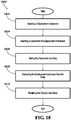
- FIG. 18 is a block diagram illustrating an example of a method 1800 for implanting an implantable device into the bladder, such as an embodiment of one of the implantable drug delivery devices described herein.
- a deployment instrument is inserted into the body.
- the deployment instrument may be inserted into the urethra and driven forward until a distal end of the deployment instrument is positioned in the bladder while a proximal end remains outside of the body.
- the device is inserted into the deployment instrument.
- inserting the device into the deployment instrument can include deforming the device from a retention shape to a deployment shape.
- the order of blocks 1802 and 1804 is reversed.
- the device is driven into the bladder.
- Driving the device from the deployment instrument removes the force of the deployment instrument wall from the device, which may cause the device to naturally return to a retention shape for retention in the bladder.
- the device may be manipulated into a retention shape or the device may be anchored in the bladder.
- the deployment instrument is removed from the body.
- the device is retained within the body.
- the device either free floats in the bladder or is anchored therein to the bladder wall.
- the device may be retained for an extended period, such as a period of hours, days, weeks, or months.
- the device is an implantable drug delivery device, the device remains implanted to release drug from the device into the bladder, such as to the urothelial tissues and other local or regional tissues. Subsequently, the device may be removed or resorbed.
- the devices described herein can be used to deliver essentially any drug or combination of drugs for treatment or prophylaxis of a variety of conditions and diseases.
- the devices are useful for treatment of genitourinary tissue sites.
- the implantable drug delivery device is used to provide pain relief to the patient.
- the drug delivery device is used to treat inflammatory conditions such as interstitial cystitis, radiation cystitis, painful bladder syndrome, prostatitis, urethritis, post-surgical pain, and kidney stones.
- the drug delivery device is used to treat urinary incontinence, frequency, or urgency, including urge incontinence and neurogenic incontinence, as well as trigonitis.
- the drug delivery device is used to treat urinary tract cancer, such as bladder cancer and prostate cancer.
- the drug delivery device is used to treat infections involving the bladder, the prostate, and the urethra.
- the drug delivery device is used to treat fibrosis of a genitourinary site, such as the bladder or uterus. Drugs suitable for use in the implantable drug delivery devices described herein are known in the art and/or are described in the patent applications that are cited above.
Landscapes
- Health & Medical Sciences (AREA)
- Engineering & Computer Science (AREA)
- Hematology (AREA)
- General Health & Medical Sciences (AREA)
- Medicinal Chemistry (AREA)
- Anesthesiology (AREA)
- Biomedical Technology (AREA)
- Heart & Thoracic Surgery (AREA)
- Chemical & Material Sciences (AREA)
- Life Sciences & Earth Sciences (AREA)
- Animal Behavior & Ethology (AREA)
- Bioinformatics & Cheminformatics (AREA)
- Public Health (AREA)
- Veterinary Medicine (AREA)
- Prostheses (AREA)
- Media Introduction/Drainage Providing Device (AREA)
- Materials For Medical Uses (AREA)
- Medicinal Preparation (AREA)
- Infusion, Injection, And Reservoir Apparatuses (AREA)
Description
- The present disclosure generally relates to implantable medical devices, and more particularly relates to implantable devices for controlled drug delivery to the bladder and other genitourinary sites.
- Systems for delivering drug locally to the bladder are known. For example, instillation permits delivering a solution of drug locally to the bladder, but drawbacks are present, such as the inability to achieve continuous drug delivery over an extended period. Continuous drug delivery can be achieved from implantable devices, but many implantable devices are not suited for the bladder. For example, some implantable devices are excreted from the bladder under the forces of urination, frustrating drug delivery. Also, many implantable devices cannot fit through the urethra, preventing minimally invasive deployment through this natural pathway. Other devices may fit through the urethra in an unfilled state but must be loaded with the drug after implantation. Furthermore, many known implantable devices cannot achieve sustained and controlled delivery of a therapeutically effective amount of drug over an extended period. For example, some known devices that are small enough to be deployed through the urethra are too small to hold a sufficiently large drug payload. Implantable medical devices for drug delivery within the bladder or other body cavities are known from
US 2009/0149833 A1 andWO 99/24106 A1 - A need therefore exists for implantable devices that can be deployed through a natural orifice and/or lumen of the body into a body cavity, such as through the urethra into the bladder, and can be retained in the body under expected conditions, such as within the bladder during urination. Preferably the devices provide controlled release of one or more drugs for an extended period following implantation.
- Implantable drug delivery devices according to claims 1, 4, and 6 are provided In addition, further advantageous embodiments follow from the dependent claims. These implantable drug delivery devices provide a device deployable through a natural orifice and/or lumen of the body into a body cavity, such as through the urethra into the bladder, and that can be retained in the body under expected conditions, such as within the bladder during urination, during a period of controlled release of one or more drugs.
-
-
FIG. 1 illustrates an embodiment of an implantable drug delivery device,FIG. 1A illustrating the device in a deployment shape andFIG. 1B illustrating the device in a retention shape. -
FIG. 2 illustrates another embodiment of an implantable drug delivery device,FIG. 2A illustrating the device in a deployment shape andFIG. 2B illustrating the device in a retention shape. -
FIG. 3 illustrates another example of an implantable drug delivery device,FIG. 3A illustrating the device in a deployment shape andFIG. 3B illustrating the device in a retention shape. -
FIG. 4 illustrates another example of an implantable drug delivery device,FIG. 4A illustrating the device in a deployment shape andFIG. 4B illustrating the device in a retention shape. -
FIG. 5 illustrates another example of an implantable drug delivery device, whereinFIG. 5A illustrates the device in a deployment shape,FIG. 5B illustrates the device in a retention shape, andFIG. 5C illustrates the device in an excretion shape. -
FIG. 6 illustrates another example of an implantable drug delivery device,FIG. 6A illustrating the device in a deployment shape andFIG. 6B illustrating the device in a retention shape. -
FIG. 7 illustrates another example of an implantable drug delivery device,FIG. 7A illustrating the device in a deployment shape andFIG. 7B illustrating the device in a retention shape. -
FIG. 8 illustrates another example of an implantable drug delivery device,FIG. 8A illustrating the device in a deployment shape andFIG. 8B illustrating the device in a retention shape. -
FIG. 9 illustrates another example of an implantable drug delivery device, whereinFIG. 9A is a cross-sectional view of the device in a deployment shape,FIG. 9B is a cross-sectional view of the device in an implanted shape, andFIG. 9C is a side view of the device in the implanted shape. -
FIG. 10 illustrates another embodiment of an implantable drug delivery device,FIG. 10A illustrating the device in a deployment shape andFIG. 10B illustrating the device in a retention shape. -
FIG. 11 illustrates another example of an implantable drug delivery device,FIG. 11A illustrating the device in a deployment shape andFIG. 11B illustrating the device in a retention shape. -
FIG. 12 illustrates another example of an implantable drug delivery device,FIG. 12A illustrating the device in a deployment shape andFIG. 12B illustrating the device in a retention shape. -
FIG. 13 illustrates another example of an implantable drug delivery device, whereinFIG. 13A illustrates the device in a deployment shape andFIG. 13B illustrates the device in an implanted shape. -
FIG. 14 illustrates another example of an implantable drug delivery device, whereinFIG. 14A illustrates the device unanchored to the bladder wall andFIG. 14B illustrates the device anchored to a portion of the bladder wall. -
FIG. 15 illustrates another example of an implantable drug delivery device, whereinFIG. 15A illustrates the device unanchored to the bladder wall andFIG. 15B illustrates the device anchored to a portion of the bladder wall. -
FIG. 16 illustrates another example of an implantable drug delivery device, whereinFIG. 16A illustrates a plan view of the device andFIG. 16B illustrates a cross-sectional view of the device. -
FIG. 17 is a sagittal view of a male genitourinary system, illustrating a drug delivery device being deployed into the bladder. -
FIG. 18 is a block diagram illustrating an example of a method for implanting an implantable device into the bladder. - Described herein are implantable devices that can be deployed through a natural orifice or lumen of the body into a body cavity and can be retained in the body cavity once implanted. In particular embodiments, the devices can deliver drug locally to the implantation site or regionally once implanted. For the purposes of the present disclosure, the term "implantation site" generally refers to a site within the body of a human patient or other animal. The implantation site can be any genitourinary site, such as the bladder, urethra, ureters, kidneys, prostate, seminal vesicles, ejaculatory duct, vas deferens, vagina, uterus, fallopian tubes, ovaries or any other location within a urological or reproductive system of the body, among other locations. According to the invention, the implantation site is the bladder.
- Devices for the bladder can be deployed through the urethra into the bladder in a minimally invasive deployment procedure. For example, the devices may be deployed through a deployment instrument, such as a catheter or cystoscope, that extends through the urethra to the bladder. Once implanted, the devices overcome the forces of urination to remain in the bladder, permitting drug delivery. Sustained and continuous delivery of an effective quantity of drug over an extended period may be enabled. The devices build upon those described in the following U.S. patent applications:
U.S. Application No. 11/463,956, filed August 11, 2006 U.S. Application No. 12/333,182, filed December 11, 2008 U.S. Application No. 12/538,580, filed August 10, 2009 U.S. Application No. 12/825,215, filed June 28, 2010 U.S. Application No. 12/825,238, filed June 28, 2010 U.S. Provisional Application No. 61/241,277, filed September 10, 2009 - Embodiments of devices disclosed herein generally have at least one drug component. The drug component may include a drug and a drug reservoir. The drug may be in solid, semi-solid, or liquid form, and the drug reservoir may be a tube or other hollow structure that houses the drug. The drug reservoir may at least partially shield the drug from direct exposure to the implantation environment and may at least partially control release of the drug into the implantation environment.
- The drug component also may be a solid drug form designed for extended release in response to direct exposure to the implantation environment. That is, the drug may be in a solid form that can be operably associated with a retention structure to provide controlled release of the therapeutic or prophylactic agent, without having a separate housing structure. For example, a therapeutic agent may be combined with (e.g., dispersed within) a matrix material in solid form and/or may have a controlled release coating thereon. The drug may be in the form of, for instance, a solid bead or disk that can be affixed to a retention structure.
- The devices generally have a deployment shape suited for deployment through a deployment instrument placed in the urethra or another natural lumen of the body. The deployment shape may be relatively elongated or linear. For example, the device may have a reduced width with reference to its length when in the deployment shape. Although the deployment shape facilitates deployment into the body, the deployment shape may increase the likelihood of excretion of the device from the body once implanted, such as during urination. Therefore, the devices are further configured for retention in the body.
- Some device embodiments are retained in the body by assuming a retention shape. The device in the retention shape occupies a larger area or volume than the device in the deployment shape, reducing the likelihood of excretion while permitting the device to free-float in the bladder. Other examples of devices are retained in the body by anchoring to a portion of the body, such as to the bladder wall. Anchoring prevents the device from free floating in the bladder, retaining the device in the bladder with reduced likelihood of excretion.
- In certain embodiments, the device is associated with at least one retention structure. The retention structure may retain the device in the retention shape, or the retention structure may anchor the device to the body. Combinations of both retention modes are possible. Example retention structures include a string, wire, thread, cord, or other filament; a web, film, sheet, or other membrane; a balloon, basket, sponge, or other projection; two magnets, a hook and eye, a screw and threaded opening, or other fastener or lock; or a tether, screw, or other anchor, among others or combinations thereof.
- In those embodiments in which the device achieves a retention shape, the retention structure may cause the drug component to achieve the retention shape or the retention structure itself may achieve the retention shape, either with or without changing the shape of the drug component. The retention structure may cause the device to automatically assume the retention shape once implanted, or the retention structure may be manipulated or manually adjusted after implantation to cause the device to assume the retention shape, such as with a medical instrument. The shape of the retention structure, the position of the retention structure with reference to the drug component, or both, may be altered to cause the device to assume the retention shape, and the retention structure may remain in the altered shape or position either naturally or under the influence of a fastener or lock.
- For example, the retention structure may have a memorized shape that is spontaneously assumed upon implantation, such as in response to the temperature within or upon contact with urine in the bladder or in response to the removal of the confining force of the deployment instrument from the device upon escaping from the deployment instrument. Examples include a filament that can be deformed into an elongated shape for deployment and returns to a curved or coiled shape upon implantation, a membrane that can be rolled or folded into an elongated shape for deployment and returns to an expanded shape upon implantation, or a sponge that can be compressed into reduced space for deployment and expands upon exiting the deployment instrument into the bladder or upon contacting fluid therein.
- The retention structure also may be manipulated or manually adjusted once the device is implanted to cause the device to assume the retention shape. Examples include a cord associated with the drug component that can be pulled to cause the drug component to change shape, a cord associated with multiple drug components that can be pulled to alter the position of the drug components with reference to each other, a filament or other structure that can be deformed into an expanded shape and maintains the shape once imparted, a balloon that can be filled, or a braided sleeve that can be expanded.
- Some device examples are associated with an anchor structure that can anchor the device in the body, such as a movable tab, a threaded fastener, or a tether, among others. In examples in which the device is implanted in the bladder, the anchor structure may attach the device to the bladder wall so that the device is retained therein.
- Specific embodiments will now be described by way of example. It should be understood that aspects of one of these embodiments can be combined with aspects of another of these embodiments to produce yet a further embodiment that is included within the scope of the present disclosure.
-
FIG. 1 illustrates an implantabledrug delivery device 100, wherein the drug component includes adrug reservoir 102 loaded withdrug 112 and the retention structure includes twofilaments fastener 130. As shown, thedrug reservoir 102 is an elongated tube that can be deformed between a relatively linear deployment shape, such as the shape shown inFIG. 1A , and a relatively circular retention shape, such as the shape shown inFIG. 1B . Thedrug 112 may be loaded in the tube in a flexible form, so that thedrug reservoir 102 can be moved between the two shapes. For example, thedrug 112 may be a number of solid drug tablets, a liquid, or a gel. Thefilaments drug reservoir 102 and joined by thefastener 130. Thefastener 130 can be adjusted to adjust the position of onefilament 120 with reference to the other 122, thereby adjusting the position of one end of thedrug reservoir 102 with reference to the other end. Thedevice 100 can assume the retention shape by adjusting thefilaments drug reservoir 102 closer together, and thereafter thedevice 100 can be retained in the retention shape by preventing adjustment of thefilaments fastener 130. In such an embodiment, thedevice 100 is manually adjusted into the retention shape by manually adjusting thefilaments device 100 is implanted. - In the illustrated embodiment, the
fastener 130 is a cinch nut that permits shortening the portion of thefilaments filaments drug reservoir 102 can be drawn closer together by pulling one or both of thefilaments device 100 to assume the retention shape. Once thefilaments filaments device 100 into the retention shape once implanted merely requires pulling one or both of thefilaments other fasteners 130 that require separate manipulation can be employed. Other fasteners may also be used. Examples are shown below inFIGS. 11-13 . - To remove the
device 100, one or both of thefilaments drug reservoir 102 to return to the deployment shape. Thereafter, thedevice 100 may be pulled through the urethra. Alternatively, all or a portion of thedevice 100 can be formed of a bioresorbable (e.g., biodegradable or bioerodible) material. In one case, the degradation of the device is substantial enough that it negates the need for a removal procedure, as the degradation products can be excreted. In another case, thefastener 130,filaments drug reservoir 102 is configured to degrade after a period (e.g., post drug release) to cause a break therein to release the tension holding thedevice 100 in the retention shape and permitting it to return to the deployment shape for retrieval through the urethra. -
FIG. 2 illustrates an implantabledrug delivery device 200, wherein the drug component includes a number ofdrug reservoirs filament 220 associated with afastener 230. As shown, thedrug reservoirs joints drug reservoir joints device 200 can be adjusted between a relatively linear deployment shape, such as the shape shown inFIG. 2A , and a relatively expanded retention shape, such as the square shape shown inFIG. 2B . - To maintain the
device 200 in the retention shape once so adjusted, thefilament 230 extends from one of thejoints 240 through anopening 250 in an opposite joint 246. The filament has a locking bead positioned on it, which serves as thefastener 230. The locking bead is positioned at an appropriate distance on thefilament 220 such the locking bead is located within a boundary of thedevice 200 when the device is in the deployment shape and outside of the device boundary when thedevice 200 is in the retention shape. Although the locking bead is sized slightly larger than theopening 250, the structure defining theopening 250 has sufficient flexibility such that the locking bead can pass through theopening 250 when thefilament 230 is forcefully pulled. Thereafter, theopening 250 returns to a position that prevents passage of the locking bead, maintaining the relative positions of thedrug reservoirs device 200 in the retention shape. Thus, moving thedevice 200 from the deployment shape to the retention shape merely requires pulling thefilament 220 until the locking bead passes through theopening 250. It should be noted that four elongated,tubular drug reservoirs drug reservoirs fastener 230 other than a filament associated with a locking bead. -
FIG. 3 illustrates an implantabledrug delivery device 300, wherein the drug component includes a number ofdrug beads 302, and the retention structure includes afilament 320. Thedrug beads 302 are positioned along thefilament 320. Thebeads 302 provide controlled release of the drug in vivo. In one example, the drug bead is in the form of a bioresorbable matrix material in which a drug is dispersed. In another example, the bead may be a compressed drug tablet having a bioresorbable coating thereon. Fivespherical drug beads 302 are shown inFIG. 3 , although any number or shape may be used. Thedrug beads 302 also could be substituted with drug reservoirs housing a drug, or a combination of drug bead and drug reservoirs could be used to provide complementary drug release profiles (e.g., one or more units for immediate release with one or more units for delayed release). - The
filament 320 is formed from a shape-memory material that is preprogrammed to assume a retention shape but can be deformed or adjusted into other shapes. Thus, thedevice 300 can be adjusted into a relatively linear deployment shape, such as the shape shown inFIG. 3A , and upon exiting the deployment instrument into the bladder, thedevice 300 automatically assumes the relatively expanded and curved retention shape, such as the shape shown inFIG. 3B . It should be noted that the illustrated retention shape is merely one example. In other examples, the filament may be preprogrammed to assume other non-linear, expanded shapes. Thefilament 320 also may be formed from a material that does not have shape memory but instead can maintain an imparted shape once manipulated. In such cases, the filament is manually adjusted into the retention shape once implanted in the bladder. -
FIG. 4 illustrates another implantabledrug delivery device 400, wherein the retention structure includes afilament 420 and the drug component includesdrug reservoirs drug 412 positioned on ends of thefilament 420. Twospherical drug reservoirs filament 420 may be formed from an elastic wire that is preprogrammed to assume a retention shape but can be deformed or adjusted into other shapes. Thus, thedevice 400 may be adjusted into a relatively linear deployment shape, such as the shape shown inFIG. 4A , and upon exiting the deployment instrument into the bladder, thedevice 400 may automatically assume the relatively expanded and curved retention shape, such as the shape shown inFIG. 4B . The illustrated retention shape is merely one example, as the filament may be preprogrammed to assume other non-linear, expanded shapes. Thefilament 420 also may be formed from a shape-memory material other than elastic wire, or from a material that does not have shape memory but instead can maintain an imparted shape once manipulated. In such cases, the filament may be manually adjusted into the retention shape in the bladder. -
FIG. 5 illustrates an implantabledrug delivery device 500, wherein the drug component includes adrug disk 502, and the retention structure includes afilament 520. Thedrug disk 502 is positioned on thefilament 520 such that ends or other portions of thefilament 520 are embedded in thedisk 502. Thedrug disk 502 may be constructed with a bioresorbable matrix material and/or a coating to provide controlled release of the drug, much like the drug beads described above with reference toFIG. 4 . Thefilament 520 may be formed from a shape-memory material that is preprogrammed to assume a retention shape. Thus, thefilament 520 may be adjusted into a relatively linear deployment shape, such as the shape shown inFIG. 5A , and upon exiting the deployment instrument into the bladder, thefilament 520 may automatically assume a relatively expanded retention shape, such as the "figure eight" shape shown inFIG. 5B . Upon absorption of thedrug disk 502, the ends or other embedded portions of thefilament 520 are released, causing thefilament 520 to return to an elongated configuration, shown inFIG. 5C , for excretion from the bladder. Thus, thedevice 500 may not require a medical procedure to be removed. It should be noted that, in other examples, the drug disk can have other shapes and the retention shape may be other than a figure eight. -
FIG. 6 illustrates an implantabledrug delivery device 600, wherein the retention structure is aflexible web 620 and the drug components are embedded in the web. Theweb 620 may be deformed into a folded deployment shape, shown inFIG. 6A , and upon exiting the deployment instrument into the bladder, the web may automatically assume the relatively, flat expanded shape shown inFIG. 6B . For example, theflexible web 620 may be elastic and may naturally have a substantially flat shape (in the absence of compressive forces). Arelief opening 650 may or may not be provided in a central portion of theweb 620 to facilitate folding and reduce bunching of theweb 620 when in the deployment shape. Therelief opening 650 also may permit urine to flow through theweb 620 once implanted in the bladder. In certain examples, additional relief openings are provided through other portions of the web so that greater fluid flow is permitted. As shown, theweb 620 may be somewhat star-shaped and the drug components may be elongateddrug reservoirs 602 that extend radially outward about theweb 620. However, other web shapes and other drug reservoir numbers, shapes and positions can be used. - For example,
FIG. 7 illustrates another implantabledrug delivery device 700, wherein the retention structure is aweb 720 that is relatively circular in shape. Theweb 720 has elongatedrelief openings 750 formed through its surface, aligned with each other. Therelief openings 750 are interspaced withdrug reservoirs 702 loaded withdrug 712 embedded in theweb 720. Theweb 720 may be rolled into a deployment shape, shown inFIG. 7A , and upon exiting the deployment instrument into the bladder, theweb 720 may automatically assume the relatively, flat expanded shape shown inFIG. 7B . - In various examples of the devices shown in
FIG. 6 andFIG. 7 , the web may be formed of a biocompatible flexible polymeric sheet. The sheet may be bioresorbable. The solid drug components may be attached to the outside surface(s) of the web, or they may be integrated into a drug reservoir formed in the web. For example, the drug reservoir may be in the form of a space formed entirely or partially by the web. In one case, the drug component is sandwiched between two thin sheets that are stacked and adhered together about a periphery of each drug component. In another case, the drug components are secured in grooves or within elongated apertures in the web. The drug components may be in the form of solid drug rods, which may be constructed of a bioresorbable matrix material (mixed with a drug) and/or a coating to provide controlled release of the drug. Such drug rods may be formed by casting or compression molding, for example, of drug alone or in combination with one or more binders or other excipients. -
FIG. 8 illustrates another implantabledrug delivery device 800, wherein the drug component is adrug reservoir 802 loaded with drug, and the retention structure includes a number ofinflatable balloons 860 in communication with aninflation port 870. The drug component may be elongated and may or may not be deformable, either due to the rigidity of thedrug reservoir 802 or the drug. When theballoons 860 are not inflated, thedevice 800 takes on a relatively linear deployment shape, such as the shape shown inFIG. 8A , and when theballoons 860 are inflated, thedevice 800 assumes a retention shape, such as the shape shown inFIG. 8B . The balloons may be inflated by directing a fluid (e.g., air, saline) through theinflation port 870 after thedevice 800 is implanted. In the illustrated example, twoballoons 860 are positioned on opposite ends of thedrug reservoir 802, and theballoons 860 assume arched or hooked shapes upon inflation, although other numbers, positions, and inflated shapes can be used. Theinflated balloons 860 may advantageously enhance the buoyancy of thedevice 800 within the bladder. -
FIG. 9 illustrates another implantabledrug delivery device 900, wherein the drug component is adrug reservoir 902 loaded withdrug 912, and the retention structure includes a number ofsponges 960. The drug component may be elongated and may or may not be deformable, either due to the rigidity of thedrug reservoir 902 or thedrug 912. Thesponges 960 may be capable of assuming a reduced volume, either when compressed or in a dehydrated state. When thesponges 960 are compressed, or are in a dehydrated state, thedevice 900 takes on a relatively linear deployment shape, such as the shape shown inFIG. 9A , and when thesponges 960 are expanded, or hydrated, thedevice 900 assumes a retention shape, such as the shape shown inFIG. 9B . Thesponges 960 may automatically expand upon exiting the deployment instrument or in response to contacting and absorbing fluid in the bladder. In the illustrated example, twosponges 960 are positioned on opposite ends of thedrug reservoir 902, and thesponges 960 assume wheel shapes upon expansion, although other numbers, positions, and expanded shapes can be used. In some examples, the sponges may be formed of a bioresorbable material that after swelling will degrade over time. -
FIG. 10 illustrates an implantabledrug delivery device 1000, wherein the drug component includes adrug reservoir 1002 loaded with drug and the retention structure includes abraided basket 1060 associated with twofilaments fastener 1030. Thedrug reservoir 1002 is an elongated tube that can be compressed along its length, much like a bellows. The drug may be loaded in thedrug reservoir 1002 in a flexible form, so that thedrug reservoir 1002 can be compressed along its length. For example, the drug may be a number of solid drug tablets, a liquid, or a gel. Thebraided basket 1060 may be positioned about the exterior of thedrug reservoir 1002, attached to thedrug reservoir 1002 via thefilaments drug reservoir 1002 between thedrug reservoir 1002 and thebraided basket 1060. Thefilaments device 1000 with thefastener 1030. - The
device 1000 generally assumes an elongated deployment shape, shown inFIG. 10A . Once implanted, thefilaments drug reservoir 1002, causing thebraided basket 1060 to expand outward about its exterior, such that thedevice 1000 assumes the retention shape shown inFIG. 10B . Thereafter thedevice 1000 can be retained in the retention shape by preventing adjustment of thefilaments fastener 1030. In such an embodiment, thedevice 1000 is manually adjusted into the retention shape by manually adjusting thefilaments device 1000 is implanted. - In the illustrated embodiment, the
fastener 1030 is a cinch nut that permits shortening but prevents lengthening thefilaments braided basket 1060 anddrug reservoir 1002 can be drawn into a reduced length by pulling thefilaments device 1000 to assume the retention shape. Once thefilaments filaments device 1000 in the retention shape. Thus, manually adjusting thedevice 1000 into the retention shape once implanted merely requires pulling thefilaments - To remove the
device 1000, thefilaments drug reservoir 1002 to return to the deployment shape. Thereafter, thedevice 1000 may be pulled through the urethra. Alternatively, all or a portion of thedevice 1000 can be formed of a bioresorbable material, such as described above with reference toFIG. 1 , so that a retrieval procedure is unnecessary. -
FIGS. 11-13 illustrate implantabledrug delivery devices drug reservoir magnets drug reservoir 1102, as shown inFIG. 11 , ahook 1230 and aneye loop 1232 associated with opposite ends of thedrug reservoir 1202, as shown inFIG. 12 , or ascrew 1330 and threadedopening 1332 associated with opposite ends of thedrug reservoir 1302, as shown inFIG. 13 . Thedrug reservoir FIGS. 11A, 12A, and 13A , and a relatively circular retention shape shown inFIGS. 11B, 12B, and 13B . Once thedevice device magnets FIG. 11B , thehook 1230 can be attached to theeye loop 1232, as shown inFIG. 12B , and thescrew 1330 can be threaded into the threadedopening 1332, as shown inFIG. 13B . In particular, thescrew 1330 is engaged about a central portion and is rotated to thread thescrew 1330 into the threadedopening 1332, as thehead 1334 of the screw may be housed in a cavity in thedrug reservoir 1302 that is sized and shaped to permit free rotation of thehead 1334 with reference to thedrug reservoir 1302. -
FIG. 14 illustrates an implantabledrug delivery device 1400, wherein the drug component is adrug reservoir 1402 loaded withdrug 1412, and the retention structure is ananchor 1430 connected viatether 1420 to thedrug reservoir 1402. Theanchor 1430 may be T-shaped and may fold downward for deployment through the deployment instrument into the bladder, as shown inFIG. 14A . Once in the bladder, theanchor 1430 engages thebladder wall 1480 to anchor thedevice 1400 therein, as shown inFIG. 14B . Anchors with other configuration may be used, or the anchor may be omitted completely, in which case the tether may be attached to the bladder wall using a mucoadhesive material known in the art. In some examples, theanchor 1430 may be bioresorbable so that theanchor 1430 does not need to be removed, in which case thedevice 1400 can be removed by cutting thetether 1420 and extracting thedrug reservoir 1402 from the bladder. Alternatively, thedrug reservoir 1402 also may be bioresorbable, or thedrug reservoir 1402 may be substituted with a solid drug form that is not housed in a drug reservoir. Thetether 1420 may be either bioresorbable or excretable, so that thedevice 1400 is completely resorbable or does not otherwise require separate removal. -
FIG. 15 illustrates an implantabledrug delivery device 1500, wherein the drug component is adrug reservoir 1502 loaded withdrug 1512, and the retention structure is a threadedanchor 1530 positioned on one end of thedrug reservoir 1502. Theentire device 1500 may be elongated, as shown inFIG. 15A , for deployment through a deployment instrument. Once in the bladder, theanchor 1530 may threadingly engage thebladder wall 1580 to anchor the device therein, as shown inFIG. 15B . In some examples, the threadedanchor 1530 may be configured for easy grasping with an insertion instrument. For example, the threadedanchor 1530 may be attached to thedrug reservoir 1502 at ahead portion 1532, which may includedetents 1534 that facilitate engaging thedevice 1500 with forceps or another insertion tool. The threadedanchor 1530 also may be omitted, in which case thedrug reservoir 1502 may be attached to the bladder wall using a mucoadhesive material. -
FIG. 16 illustrates an implantabledrug delivery device 1600, wherein the drug component includes adrug reservoir 1602 housing a number ofdrug doses 1612, and the retention structure is a threadedanchor 1630 positioned on one end of thedrug reservoir 1602. Theentire device 1600 may be elongated, as shown inFIG. 16A , for deployment through a deployment instrument. Once in the bladder, the threadedanchor 1630 may threadingly engage the bladder wall to anchor thedevice 1600 therein. Thedrug reservoir 1602 is formed from a bioresorbable material that can degrade in the implantation environment. Thedrug reservoir 1602 is shaped so that the material thickness increases along the length of thedevice 1600, either uniformly or in a stepped fashion as shown inFIG. 16A . A number ofdrug doses 1612 are housed within the material, as shown inFIG. 16B , and the drug doses 1612 are exposed as the material degrades. Because thedrug reservoir 1602 degrades at a varying rate along the length of thedevice 1600 due to the variation in material thickness, the drug doses 1612 are released at varying rates. -
FIG. 17 is a sagittal view of a male genitourinary system, illustrating an implantabledrug delivery device 1700 being deployed through adeployment instrument 1790 into an implantation site. By way of example, the male anatomy is shown and the implantation site is shown as thebladder 1780. Thedrug delivery device 1700 may be an embodiment of one of the implantable drug delivery devices described herein. Thedeployment instrument 1790 may be any device designed to navigate natural lumens of the body to reach the intended implantation site. For deployment in thebladder 1780, thedeployment instrument 1790 is sized and shaped for passing through aurethra 1782 of a patient to abladder 1780 as shown. Thedeployment instrument 1790 may be a known device, such as a catheter or cystoscope, or a specially designed device, such as an one of the deployment instruments described inU.S. Provisional Application No. 61/241,229, filed on September 10, 2009 U.S. Provisional Application No. 61/311,103, filed on March 5, 2010 deployment instrument 1790 is used to deploy theimplantable device 1700 into the body and is subsequently removed from the body, leaving theimplantable device 1700 wholly implanted in the body, either free-floating therein or anchored thereto. Once so implanted, thedevice 1700 may release drug into the body for an extended period. A comparable procedure can be used to deploy any of the devices described herein into other parts of the body through other natural lumens. -
FIG. 18 is a block diagram illustrating an example of amethod 1800 for implanting an implantable device into the bladder, such as an embodiment of one of the implantable drug delivery devices described herein. Inblock 1802, a deployment instrument is inserted into the body. The deployment instrument may be inserted into the urethra and driven forward until a distal end of the deployment instrument is positioned in the bladder while a proximal end remains outside of the body. - In
block 1804, the device is inserted into the deployment instrument. In some cases, inserting the device into the deployment instrument can include deforming the device from a retention shape to a deployment shape. In some cases, the order ofblocks - In
block 1806, the device is driven into the bladder. Driving the device from the deployment instrument removes the force of the deployment instrument wall from the device, which may cause the device to naturally return to a retention shape for retention in the bladder. Alternatively, the device may be manipulated into a retention shape or the device may be anchored in the bladder. - In
block 1808, the deployment instrument is removed from the body. Thereafter, inblock 1810, the device is retained within the body. The device either free floats in the bladder or is anchored therein to the bladder wall. The device may be retained for an extended period, such as a period of hours, days, weeks, or months. In embodiments in which the device is an implantable drug delivery device, the device remains implanted to release drug from the device into the bladder, such as to the urothelial tissues and other local or regional tissues. Subsequently, the device may be removed or resorbed. - The devices described herein can be used to deliver essentially any drug or combination of drugs for treatment or prophylaxis of a variety of conditions and diseases. In a certain application, the devices are useful for treatment of genitourinary tissue sites. In one embodiment, the implantable drug delivery device is used to provide pain relief to the patient. In other embodiments, the drug delivery device is used to treat inflammatory conditions such as interstitial cystitis, radiation cystitis, painful bladder syndrome, prostatitis, urethritis, post-surgical pain, and kidney stones. In still other embodiments, the drug delivery device is used to treat urinary incontinence, frequency, or urgency, including urge incontinence and neurogenic incontinence, as well as trigonitis. In yet another embodiment, the drug delivery device is used to treat urinary tract cancer, such as bladder cancer and prostate cancer. In still another embodiment, the drug delivery device is used to treat infections involving the bladder, the prostate, and the urethra. In other embodiments, the drug delivery device is used to treat fibrosis of a genitourinary site, such as the bladder or uterus. Drugs suitable for use in the implantable drug delivery devices described herein are known in the art and/or are described in the patent applications that are cited above.
Claims (9)
- An implantable drug delivery device (100) for controlled drug delivery to the bladder or other genitourinary sites, comprising:a drug reservoir (102), the drug reservoir (102) having an elongated shape, the drug reservoir (102) formed from a deformable material;a drug (112) loaded in the drug reservoir (102);characterized in that the implantable drug delivery device comprises:a first filament (120) attached to a first end of the drug reservoir (102);a second filament (122) attached to a second end of the drug reservoir (102); anda fastener (130) positioned about the first and second filaments (120, 122), the fastener (130) permitting shortening and preventing lengthening of the filaments (120, 122) with reference to the ends of the drug reservoir (102).
- The implantable drug delivery device (100) of claim 1, wherein the fastener (130) comprises a cinch nut.
- The implantable drug delivery device (100) of claim 1 or 2, wherein the fastener (130) is adjustable to enable the device (100) to be deformed from a relatively linear deployment shape to a relatively circular retention shape.
- An implantable drug delivery device (200) for controlled drug delivery to the bladder or other genitourinary sites, comprising:a plurality of drug reservoirs (202, 204, 206, 208);a drug loaded in the drug reservoirs (202, 204, 206, 208);characterized in that the implantable drug delivery device comprises:a plurality of flexible joints (240, 242, 244, 246) joining the drug reservoirs (202, 204, 206, 208) together at their ends, at least one of the flexible joints (240, 242, 244, 246) having an opening (250);a filament (220) extending from one of the flexible joints (240, 242, 244, 246) through the opening 250); anda fastener (230) positioned on the filament (220), the fastener (230) being movable through the opening (250) upon engagement of the filament (220) to lock the drug reservoirs (202, 204, 206, 208) in a retention shape.
- The implantable drug delivery device (200) of claim 4, wherein the fastener (230) comprises a locking bead.
- An implantable drug delivery device (1000) for controlled drug delivery to the bladder or other genitourinary sites, characterized in that the device comprises:a bellows-shaped drug reservoir (1002);a drug loaded in the drug reservoir (1002);a braided basket (1060) positioned about the drug reservoir (1002);two filaments (1020, 1022) positioned between the drug reservoir (1002) and the braided basket (1060), attached to both; anda fastener (1030) associated with the filaments (1020, 1022), wherein the device (1000) can be moved into a retention shape of increased width and reduced length by pulling the filaments (1020, 1022) through the fastener (1030), causing the basket (1060) to expand outward.
- The implantable drug delivery device (100) of any one of claims 1 to 3, wherein the drug reservoir (102) comprises a hollow tube or other hollow structure that houses the drug (112).
- The implantable drug delivery device (100) of any one of claims 1 to 3 or 7, wherein all or a portion of the device (100) is formed of a bioresorbable material.
- The implantable drug delivery device (100) of any one of claims 1 to 3, 7 or 8, which is configured for insertion through a patient's urethra and subsequent retention in the patient's bladder.
Priority Applications (3)
| Application Number | Priority Date | Filing Date | Title |
|---|---|---|---|
| EP19161525.1A EP3517101B1 (en) | 2010-08-05 | 2011-08-03 | Implantable drug delivery devices for genitourinary sites |
| EP20172722.9A EP3711750B1 (en) | 2010-08-05 | 2011-08-03 | Implantable drug delivery devices for genitourinary sites |
| EP23168676.7A EP4241764A3 (en) | 2010-08-05 | 2011-08-03 | Implantable drug delivery devices for genitourinary sites |
Applications Claiming Priority (2)
| Application Number | Priority Date | Filing Date | Title |
|---|---|---|---|
| US37090210P | 2010-08-05 | 2010-08-05 | |
| PCT/US2011/046439 WO2012018923A1 (en) | 2010-08-05 | 2011-08-03 | Implantable drug delivery devices for genitourinary sites |
Related Child Applications (3)
| Application Number | Title | Priority Date | Filing Date |
|---|---|---|---|
| EP19161525.1A Division EP3517101B1 (en) | 2010-08-05 | 2011-08-03 | Implantable drug delivery devices for genitourinary sites |
| EP23168676.7A Division EP4241764A3 (en) | 2010-08-05 | 2011-08-03 | Implantable drug delivery devices for genitourinary sites |
| EP20172722.9A Division EP3711750B1 (en) | 2010-08-05 | 2011-08-03 | Implantable drug delivery devices for genitourinary sites |
Publications (3)
| Publication Number | Publication Date |
|---|---|
| EP2600848A1 EP2600848A1 (en) | 2013-06-12 |
| EP2600848A4 EP2600848A4 (en) | 2018-03-28 |
| EP2600848B1 true EP2600848B1 (en) | 2019-03-20 |
Family
ID=45559809
Family Applications (4)
| Application Number | Title | Priority Date | Filing Date |
|---|---|---|---|
| EP23168676.7A Withdrawn EP4241764A3 (en) | 2010-08-05 | 2011-08-03 | Implantable drug delivery devices for genitourinary sites |
| EP19161525.1A Active EP3517101B1 (en) | 2010-08-05 | 2011-08-03 | Implantable drug delivery devices for genitourinary sites |
| EP11815265.1A Active EP2600848B1 (en) | 2010-08-05 | 2011-08-03 | Implantable drug delivery devices for genitourinary sites |
| EP20172722.9A Active EP3711750B1 (en) | 2010-08-05 | 2011-08-03 | Implantable drug delivery devices for genitourinary sites |
Family Applications Before (2)
| Application Number | Title | Priority Date | Filing Date |
|---|---|---|---|
| EP23168676.7A Withdrawn EP4241764A3 (en) | 2010-08-05 | 2011-08-03 | Implantable drug delivery devices for genitourinary sites |
| EP19161525.1A Active EP3517101B1 (en) | 2010-08-05 | 2011-08-03 | Implantable drug delivery devices for genitourinary sites |
Family Applications After (1)
| Application Number | Title | Priority Date | Filing Date |
|---|---|---|---|
| EP20172722.9A Active EP3711750B1 (en) | 2010-08-05 | 2011-08-03 | Implantable drug delivery devices for genitourinary sites |
Country Status (7)
| Country | Link |
|---|---|
| US (4) | US9283361B2 (en) |
| EP (4) | EP4241764A3 (en) |
| DK (1) | DK2600848T3 (en) |
| ES (2) | ES2822118T3 (en) |
| HU (1) | HUE051942T2 (en) |
| PL (1) | PL3517101T3 (en) |
| WO (1) | WO2012018923A1 (en) |
Families Citing this family (28)
| Publication number | Priority date | Publication date | Assignee | Title |
|---|---|---|---|---|
| US9492266B2 (en) | 2010-08-05 | 2016-11-15 | Taris Biomedical Llc | Ureteral stent drug delivery device, kit, and method |
| WO2012048104A1 (en) | 2010-10-06 | 2012-04-12 | Taris Biomedical, Inc. | Implantable drug delivery device with bladden retention feature |
| WO2012048114A1 (en) | 2010-10-06 | 2012-04-12 | Taris Biomedical, Inc. | Time-selective bioresorbable or collapsible drug delivery systems and methods |
| JP2014503554A (en) | 2011-01-10 | 2014-02-13 | タリス バイオメディカル,インコーポレイテッド | Lidocaine regimen for the use of continuous treatment of bladder pain and irritating urination |
| ES2637388T3 (en) | 2011-02-04 | 2017-10-13 | Taris Biomedical, Inc. | Implantable device for the controlled release of a low solubility drug |
| US9061125B2 (en) * | 2012-03-21 | 2015-06-23 | Ams Research Corporation | Bladder drug eluting device |
| ES3015082T3 (en) | 2012-05-19 | 2025-04-29 | Taris Biomedical Llc | Implantable urological device with retrieval feature |
| PL2968880T3 (en) | 2013-03-15 | 2025-06-23 | Taris Biomedical Llc | Drug delivery devices with drug-permeable component |
| AU2015259361B2 (en) | 2014-05-12 | 2020-11-05 | Taris Biomedical Llc | Drug delivery devices and methods |
| KR20230142816A (en) | 2014-06-26 | 2023-10-11 | 타리스 바이오메디컬 엘엘씨 | Intravesical drug delivery devices and methods including elastic polymer-drug matrix systems |
| WO2016160934A1 (en) | 2015-03-30 | 2016-10-06 | Taris Biomedical Llc | Devices and methods for local delivery of drug to upper urinary tract |
| EP4744688A2 (en) | 2015-04-23 | 2026-05-20 | Janssen Biotech Inc | Drug Dispensing Devices with Drug Permeable Component and Method |
| CN108472249A (en) | 2015-10-23 | 2018-08-31 | 林德拉有限公司 | Gastric resident system for sustained release of a therapeutic agent and method of use thereof |
| EP3386488B1 (en) * | 2015-12-08 | 2023-09-06 | Lyndra Therapeutics, Inc. | Geometric configurations for gastric residence systems |
| US11185670B2 (en) | 2016-01-26 | 2021-11-30 | Taris Biomedical Llc | Multi-lumen drug delivery devices |
| CN109310639A (en) | 2016-05-27 | 2019-02-05 | 林德拉有限公司 | Material structure for gastric retention systems |
| JP2019532947A (en) | 2016-09-30 | 2019-11-14 | リンドラ,インコーポレイティド | Gastric retention system for sustained delivery of adamantane drugs |
| US11707611B2 (en) * | 2016-11-08 | 2023-07-25 | W. L. Gore & Associates, Inc. | Implantable apparatus for retention of biological moieties |
| EP3634382A4 (en) | 2017-06-09 | 2021-07-07 | Lyndra Therapeutics, Inc. | HOME GASTRIC SYSTEMS WITH FILMS MODULATING THE RELEASE RATE |
| ES3056905T3 (en) | 2019-10-07 | 2026-02-25 | Oak Crest Inst Of Science | Orally implantable drug delivery device |
| CA3158651A1 (en) | 2019-11-27 | 2021-06-03 | Marc M. Baum | Permeable skin sustained release drug delivery device |
| EP4452385B1 (en) | 2021-12-21 | 2026-02-11 | TARIS Biomedical LLC | Urinary placement catheter for intravesical devices |
| JP2025503609A (en) | 2022-01-06 | 2025-02-04 | オーク クレスト インスティテュート オブ サイエンス | Subdermal implants for sustained drug delivery |
| WO2024092159A1 (en) | 2022-10-28 | 2024-05-02 | Taris Biomedical Llc | Methods of treating bladder cancer with gemcitabine |
| EP4694895A1 (en) | 2023-04-10 | 2026-02-18 | TARIS Biomedical LLC | Gemcitabine for use in methods of treating high-risk non-muscle invasive bladder cancer unresponsive to bacillus calmette-guerin therapy |
| EP4698151A1 (en) | 2023-04-19 | 2026-02-25 | Oak Crest Institute of Science | Vaginal drug delivery device |
| AU2024356379A1 (en) | 2023-10-02 | 2026-05-14 | Janssen Biotech, Inc. | Methods of treating high-risk non-muscle invasive bladder cancer unresponsive to bacillus calmette-guérin therapy |
| WO2026055309A1 (en) | 2024-09-04 | 2026-03-12 | Oak Crest Institute Of Science | Subdermal drug delivery devices |
Family Cites Families (44)
| Publication number | Priority date | Publication date | Assignee | Title |
|---|---|---|---|---|
| US4016251A (en) | 1972-08-17 | 1977-04-05 | Alza Corporation | Vaginal drug dispensing device |
| US3901232A (en) | 1973-10-26 | 1975-08-26 | Alza Corp | Integrated device for administering beneficial drug at programmed rate |
| US3995633A (en) * | 1975-12-02 | 1976-12-07 | The Procter & Gamble Company | Vaginal Medicament dispensing device |
| US4475916A (en) | 1982-03-18 | 1984-10-09 | Merck & Co., Inc. | Osmotic drug delivery system |
| DE3332156A1 (en) | 1983-09-06 | 1985-03-21 | Peter 6000 Frankfurt Prezelj | Nose clip |
| US4871542A (en) | 1987-04-30 | 1989-10-03 | Ferring Service Center, N.V. | Method and apparatus useful for delivering medicinal compositions into the bladder and urinary tract |
| NZ228382A (en) * | 1989-03-17 | 1992-08-26 | Carter Holt Harvey Plastic Pro | Drug administering coil-like device for insertion in body cavity of animal |
| US5334189A (en) * | 1991-06-03 | 1994-08-02 | Wade Stephen E | Device for controlled diffusion of a chemical substance |
| ES2150427T3 (en) | 1992-06-02 | 2000-12-01 | Bard Inc C R | PROCEDURE AND DEVICE OF IMPLANT FOR THE SUPPLY OF LONG-TERM DRUGS. |
| US6171298B1 (en) * | 1996-05-03 | 2001-01-09 | Situs Corporation | Intravesical infuser |
| US5868719A (en) | 1997-01-15 | 1999-02-09 | Boston Scientific Corporation | Drug delivery balloon catheter device |
| AU6876498A (en) | 1997-04-03 | 1998-10-22 | Point Biomedical Corporation | Intravesical drug delivery system |
| US6197327B1 (en) | 1997-06-11 | 2001-03-06 | Umd, Inc. | Device and method for treatment of dysmenorrhea |
| WO1999018884A1 (en) | 1997-10-10 | 1999-04-22 | Duirs Nz Limited | Drug delivery system |
| US6159143A (en) | 1998-06-17 | 2000-12-12 | Scimed Life Systems, Inc. | Method and device for delivery of therapeutic agents in conjunction with isotope seed placement |
| US6296622B1 (en) * | 1998-12-21 | 2001-10-02 | Micrus Corporation | Endoluminal device delivery system using axially recovering shape memory material |
| AU1853400A (en) | 1999-01-06 | 2000-07-24 | Richard Henry | Topical anesthesia of the urinary bladder |
| US20050238733A1 (en) | 2000-01-05 | 2005-10-27 | Richard Henry | Topical anesthesia of the urinary bladder |
| US6379382B1 (en) | 2000-03-13 | 2002-04-30 | Jun Yang | Stent having cover with drug delivery capability |
| US7232421B1 (en) | 2000-05-12 | 2007-06-19 | C. R. Bard, Inc. | Agent delivery systems |
| US6632217B2 (en) | 2001-04-19 | 2003-10-14 | Microsolutions, Inc. | Implantable osmotic pump |
| US7438701B2 (en) | 2001-07-26 | 2008-10-21 | Durect Corporation | Local concentration management system |
| US6893431B2 (en) * | 2001-10-15 | 2005-05-17 | Scimed Life Systems, Inc. | Medical device for delivering patches |
| DE10247689A1 (en) | 2002-10-12 | 2004-04-22 | Martin Rahe | Urinary bladder implants for prolonged prevention and treatment of urinary tract infections, comprising antimicrobial active agent, preferably silver, incorporated in carrier, preferably of shape memory material |
| US20040260272A1 (en) | 2002-10-22 | 2004-12-23 | Friedman Craig D. | Method and system for intravesicular delivery of therapeutic agents |
| US6933351B2 (en) | 2003-06-20 | 2005-08-23 | Infineum International Limited | Process for forming polyalkenyl acylating agents |
| SI1708722T1 (en) | 2004-01-28 | 2014-10-30 | The Regents Of The University Of California | Novel interstitial therapy for immediate symptom relief and chronic therapy in interstitial cystitis |
| WO2005115245A1 (en) | 2004-05-28 | 2005-12-08 | Dynaventions Inc. | Intravesicular device |
| US7731705B2 (en) * | 2005-01-10 | 2010-06-08 | Wardle John L | Eluting coils and methods of deploying and retrieving |
| US7862552B2 (en) | 2005-05-09 | 2011-01-04 | Boston Scientific Scimed, Inc. | Medical devices for treating urological and uterine conditions |
| EP1933810B1 (en) * | 2005-08-11 | 2012-10-10 | Massachusetts Institute of Technology | Intravesical drug delivery device and method |
| US20070172508A1 (en) | 2006-01-26 | 2007-07-26 | Paul Zupkas | Transluminal drug delivery methods and devices |
| EP2004172B1 (en) | 2006-03-31 | 2019-03-13 | Mati Therapeutics Inc. | Drug delivery structures and compositions for nasolacrimal system |
| EP2096983A2 (en) | 2006-09-28 | 2009-09-09 | Medvision Inc. | Examination device |
| US7862502B2 (en) * | 2006-10-20 | 2011-01-04 | Ellipse Technologies, Inc. | Method and apparatus for adjusting a gastrointestinal restriction device |
| CA2687281A1 (en) | 2007-03-20 | 2008-09-25 | Boston Scientific Limited | Urological medical devices for release of prostatically beneficial therapeutic agents |
| WO2009029958A2 (en) | 2007-08-30 | 2009-03-05 | Sunstorm Research Corporation | Implantable delivery device |
| EA201070703A1 (en) * | 2007-12-11 | 2010-12-30 | Массачусетс Инститьют Оф Текнолоджи | IMPLANTABLE DEVICE FOR DELIVERY OF MEDICATION AND METHODS OF TREATMENT OF URINARY BUBBLE AND OTHER BODY CAVITY OR TUBULAR ORGANS |
| US8303650B2 (en) * | 2008-01-10 | 2012-11-06 | Telesis Research, Llc | Biodegradable self-expanding drug-eluting prosthesis |
| US20100023056A1 (en) * | 2008-07-23 | 2010-01-28 | Guided Delivery Systems Inc. | Tether-anchor assemblies |
| EA201170297A1 (en) | 2008-08-09 | 2011-08-30 | Массачусетс Инститьют Оф Текнолоджи | IMPLANTABLE DEVICE FOR THE DELIVERY OF MEDICINES AND THE METHOD OF TREATMENT OF MALE URINS AND THE ENVIRONMENTAL TISSUES |
| US20100131043A1 (en) * | 2008-11-26 | 2010-05-27 | Casas Jesus W | Endoluminal Implants For Bioactive Material Delivery |
| CA2765630C (en) | 2009-06-26 | 2016-07-05 | Taris Biomedical, Inc. | Solid drug tablets for implantable drug delivery devices |
| US9017312B2 (en) | 2009-09-10 | 2015-04-28 | Taris Biomedical Llc | Implantable device for controlled drug delivery |
-
2011
- 2011-08-03 ES ES19161525T patent/ES2822118T3/en active Active
- 2011-08-03 EP EP23168676.7A patent/EP4241764A3/en not_active Withdrawn
- 2011-08-03 EP EP19161525.1A patent/EP3517101B1/en active Active
- 2011-08-03 EP EP11815265.1A patent/EP2600848B1/en active Active
- 2011-08-03 ES ES11815265T patent/ES2729782T3/en active Active
- 2011-08-03 DK DK11815265.1T patent/DK2600848T3/en active
- 2011-08-03 PL PL19161525.1T patent/PL3517101T3/en unknown
- 2011-08-03 WO PCT/US2011/046439 patent/WO2012018923A1/en not_active Ceased
- 2011-08-03 US US13/813,745 patent/US9283361B2/en active Active
- 2011-08-03 EP EP20172722.9A patent/EP3711750B1/en active Active
- 2011-08-03 HU HUE19161525A patent/HUE051942T2/en unknown
-
2016
- 2016-02-29 US US15/056,097 patent/US10058689B2/en active Active
-
2018
- 2018-08-27 US US16/112,859 patent/US11129973B2/en active Active
-
2021
- 2021-08-27 US US17/459,408 patent/US20210386983A1/en not_active Abandoned
Non-Patent Citations (1)
| Title |
|---|
| None * |
Also Published As
| Publication number | Publication date |
|---|---|
| PL3517101T3 (en) | 2021-02-22 |
| EP4241764A3 (en) | 2023-12-20 |
| US9283361B2 (en) | 2016-03-15 |
| US20210386983A1 (en) | 2021-12-16 |
| EP3711750B1 (en) | 2023-09-06 |
| EP3517101A1 (en) | 2019-07-31 |
| EP2600848A4 (en) | 2018-03-28 |
| EP2600848A1 (en) | 2013-06-12 |
| HUE051942T2 (en) | 2021-03-29 |
| US20160213904A1 (en) | 2016-07-28 |
| EP3711750A1 (en) | 2020-09-23 |
| US20190038883A1 (en) | 2019-02-07 |
| US11129973B2 (en) | 2021-09-28 |
| US20130131637A1 (en) | 2013-05-23 |
| EP4241764A2 (en) | 2023-09-13 |
| ES2729782T3 (en) | 2019-11-06 |
| US10058689B2 (en) | 2018-08-28 |
| DK2600848T3 (en) | 2019-06-24 |
| ES2822118T3 (en) | 2021-04-29 |
| WO2012018923A1 (en) | 2012-02-09 |
| EP3517101B1 (en) | 2020-07-15 |
Similar Documents
| Publication | Publication Date | Title |
|---|---|---|
| US11129973B2 (en) | Drug delivery devices for deployment in genitourinary sites | |
| EP3740137B1 (en) | Flow control valve | |
| US9314361B2 (en) | System and method for anchoring stomach implant | |
| US7105007B2 (en) | Cervical medical device, system and method | |
| ES2563308T3 (en) | Devices for the administration of therapeutic substances for the treatment of sinusitis | |
| US7398780B2 (en) | Contraceptive system and method of use | |
| US9713549B2 (en) | Contraceptive with permeable and impermeable components | |
| ES2293730T3 (en) | OCLUSIVE DEVICE AND EMPLOYMENT METHOD. | |
| CN101287422B (en) | Device for improving urinary incontinence in women | |
| JP5960327B2 (en) | Intravaginal device for fecal incontinence | |
| US20060089658A1 (en) | Method and apparatus for treating abnormal uterine bleeding | |
| US9566419B2 (en) | Body lumen occlusion device and method | |
| HK40038221A (en) | Implantable drug delivery devices for genitourinary sites | |
| HK40038221B (en) | Implantable drug delivery devices for genitourinary sites | |
| HK1186103B (en) | Implantable drug delivery devices for genitourinary sites | |
| HK1186103A (en) | Implantable drug delivery devices for genitourinary sites | |
| US20100160936A1 (en) | Devices and methods for reversal of permanent sterilization | |
| US8701670B2 (en) | Trackable occlusion device and catheter system |
Legal Events
| Date | Code | Title | Description |
|---|---|---|---|
| PUAI | Public reference made under article 153(3) epc to a published international application that has entered the european phase |
Free format text: ORIGINAL CODE: 0009012 |
|
| 17P | Request for examination filed |
Effective date: 20130221 |
|
| AK | Designated contracting states |
Kind code of ref document: A1 Designated state(s): AL AT BE BG CH CY CZ DE DK EE ES FI FR GB GR HR HU IE IS IT LI LT LU LV MC MK MT NL NO PL PT RO RS SE SI SK SM TR |
|
| DAX | Request for extension of the european patent (deleted) | ||
| REG | Reference to a national code |
Ref country code: HK Ref legal event code: DE Ref document number: 1186103 Country of ref document: HK |
|
| RAP1 | Party data changed (applicant data changed or rights of an application transferred) |
Owner name: TARIS BIOMEDICAL LLC |
|
| RIC1 | Information provided on ipc code assigned before grant |
Ipc: A61K 9/22 20060101AFI20171115BHEP Ipc: A61M 31/00 20060101ALI20171115BHEP |
|
| RA4 | Supplementary search report drawn up and despatched (corrected) |
Effective date: 20180227 |
|
| RIC1 | Information provided on ipc code assigned before grant |
Ipc: A61M 31/00 20060101ALI20180221BHEP Ipc: A61K 9/22 20060101AFI20180221BHEP |
|
| GRAP | Despatch of communication of intention to grant a patent |
Free format text: ORIGINAL CODE: EPIDOSNIGR1 |
|
| STAA | Information on the status of an ep patent application or granted ep patent |
Free format text: STATUS: GRANT OF PATENT IS INTENDED |
|
| INTG | Intention to grant announced |
Effective date: 20181106 |
|
| GRAS | Grant fee paid |
Free format text: ORIGINAL CODE: EPIDOSNIGR3 |
|
| GRAA | (expected) grant |
Free format text: ORIGINAL CODE: 0009210 |
|
| STAA | Information on the status of an ep patent application or granted ep patent |
Free format text: STATUS: THE PATENT HAS BEEN GRANTED |
|
| AK | Designated contracting states |
Kind code of ref document: B1 Designated state(s): AL AT BE BG CH CY CZ DE DK EE ES FI FR GB GR HR HU IE IS IT LI LT LU LV MC MK MT NL NO PL PT RO RS SE SI SK SM TR |
|
| REG | Reference to a national code |
Ref country code: GB Ref legal event code: FG4D |
|
| REG | Reference to a national code |
Ref country code: CH Ref legal event code: EP |
|
| REG | Reference to a national code |
Ref country code: DE Ref legal event code: R096 Ref document number: 602011057382 Country of ref document: DE |
|
| REG | Reference to a national code |
Ref country code: AT Ref legal event code: REF Ref document number: 1109782 Country of ref document: AT Kind code of ref document: T Effective date: 20190415 |
|
| REG | Reference to a national code |
Ref country code: IE Ref legal event code: FG4D |
|
| RAP2 | Party data changed (patent owner data changed or rights of a patent transferred) |
Owner name: TARIS BIOMEDICAL LLC |
|
| REG | Reference to a national code |
Ref country code: DK Ref legal event code: T3 Effective date: 20190617 |
|
| REG | Reference to a national code |
Ref country code: SE Ref legal event code: TRGR |
|
| REG | Reference to a national code |
Ref country code: CH Ref legal event code: NV Representative=s name: STUMP UND PARTNER PATENTANWAELTE AG, CH |
|
| REG | Reference to a national code |
Ref country code: NL Ref legal event code: MP Effective date: 20190320 |
|
| PG25 | Lapsed in a contracting state [announced via postgrant information from national office to epo] |
Ref country code: LT Free format text: LAPSE BECAUSE OF FAILURE TO SUBMIT A TRANSLATION OF THE DESCRIPTION OR TO PAY THE FEE WITHIN THE PRESCRIBED TIME-LIMIT Effective date: 20190320 |
|
| REG | Reference to a national code |
Ref country code: LT Ref legal event code: MG4D |
|
| PG25 | Lapsed in a contracting state [announced via postgrant information from national office to epo] |
Ref country code: GR Free format text: LAPSE BECAUSE OF FAILURE TO SUBMIT A TRANSLATION OF THE DESCRIPTION OR TO PAY THE FEE WITHIN THE PRESCRIBED TIME-LIMIT Effective date: 20190621 Ref country code: NL Free format text: LAPSE BECAUSE OF FAILURE TO SUBMIT A TRANSLATION OF THE DESCRIPTION OR TO PAY THE FEE WITHIN THE PRESCRIBED TIME-LIMIT Effective date: 20190320 Ref country code: HR Free format text: LAPSE BECAUSE OF FAILURE TO SUBMIT A TRANSLATION OF THE DESCRIPTION OR TO PAY THE FEE WITHIN THE PRESCRIBED TIME-LIMIT Effective date: 20190320 Ref country code: LV Free format text: LAPSE BECAUSE OF FAILURE TO SUBMIT A TRANSLATION OF THE DESCRIPTION OR TO PAY THE FEE WITHIN THE PRESCRIBED TIME-LIMIT Effective date: 20190320 Ref country code: RS Free format text: LAPSE BECAUSE OF FAILURE TO SUBMIT A TRANSLATION OF THE DESCRIPTION OR TO PAY THE FEE WITHIN THE PRESCRIBED TIME-LIMIT Effective date: 20190320 Ref country code: BG Free format text: LAPSE BECAUSE OF FAILURE TO SUBMIT A TRANSLATION OF THE DESCRIPTION OR TO PAY THE FEE WITHIN THE PRESCRIBED TIME-LIMIT Effective date: 20190620 |
|
| REG | Reference to a national code |
Ref country code: NO Ref legal event code: T2 Effective date: 20190320 |
|
| REG | Reference to a national code |
Ref country code: AT Ref legal event code: MK05 Ref document number: 1109782 Country of ref document: AT Kind code of ref document: T Effective date: 20190320 |
|
| PG25 | Lapsed in a contracting state [announced via postgrant information from national office to epo] |
Ref country code: RO Free format text: LAPSE BECAUSE OF FAILURE TO SUBMIT A TRANSLATION OF THE DESCRIPTION OR TO PAY THE FEE WITHIN THE PRESCRIBED TIME-LIMIT Effective date: 20190320 Ref country code: CZ Free format text: LAPSE BECAUSE OF FAILURE TO SUBMIT A TRANSLATION OF THE DESCRIPTION OR TO PAY THE FEE WITHIN THE PRESCRIBED TIME-LIMIT Effective date: 20190320 Ref country code: EE Free format text: LAPSE BECAUSE OF FAILURE TO SUBMIT A TRANSLATION OF THE DESCRIPTION OR TO PAY THE FEE WITHIN THE PRESCRIBED TIME-LIMIT Effective date: 20190320 Ref country code: AL Free format text: LAPSE BECAUSE OF FAILURE TO SUBMIT A TRANSLATION OF THE DESCRIPTION OR TO PAY THE FEE WITHIN THE PRESCRIBED TIME-LIMIT Effective date: 20190320 Ref country code: PT Free format text: LAPSE BECAUSE OF FAILURE TO SUBMIT A TRANSLATION OF THE DESCRIPTION OR TO PAY THE FEE WITHIN THE PRESCRIBED TIME-LIMIT Effective date: 20190720 Ref country code: SK Free format text: LAPSE BECAUSE OF FAILURE TO SUBMIT A TRANSLATION OF THE DESCRIPTION OR TO PAY THE FEE WITHIN THE PRESCRIBED TIME-LIMIT Effective date: 20190320 |
|
| REG | Reference to a national code |
Ref country code: ES Ref legal event code: FG2A Ref document number: 2729782 Country of ref document: ES Kind code of ref document: T3 Effective date: 20191106 |
|
| PG25 | Lapsed in a contracting state [announced via postgrant information from national office to epo] |
Ref country code: PL Free format text: LAPSE BECAUSE OF FAILURE TO SUBMIT A TRANSLATION OF THE DESCRIPTION OR TO PAY THE FEE WITHIN THE PRESCRIBED TIME-LIMIT Effective date: 20190320 Ref country code: SM Free format text: LAPSE BECAUSE OF FAILURE TO SUBMIT A TRANSLATION OF THE DESCRIPTION OR TO PAY THE FEE WITHIN THE PRESCRIBED TIME-LIMIT Effective date: 20190320 |
|
| PG25 | Lapsed in a contracting state [announced via postgrant information from national office to epo] |
Ref country code: AT Free format text: LAPSE BECAUSE OF FAILURE TO SUBMIT A TRANSLATION OF THE DESCRIPTION OR TO PAY THE FEE WITHIN THE PRESCRIBED TIME-LIMIT Effective date: 20190320 Ref country code: IS Free format text: LAPSE BECAUSE OF FAILURE TO SUBMIT A TRANSLATION OF THE DESCRIPTION OR TO PAY THE FEE WITHIN THE PRESCRIBED TIME-LIMIT Effective date: 20190720 |
|
| REG | Reference to a national code |
Ref country code: DE Ref legal event code: R097 Ref document number: 602011057382 Country of ref document: DE |
|
| PLBE | No opposition filed within time limit |
Free format text: ORIGINAL CODE: 0009261 |
|
| STAA | Information on the status of an ep patent application or granted ep patent |
Free format text: STATUS: NO OPPOSITION FILED WITHIN TIME LIMIT |
|
| 26N | No opposition filed |
Effective date: 20200102 |
|
| PG25 | Lapsed in a contracting state [announced via postgrant information from national office to epo] |
Ref country code: SI Free format text: LAPSE BECAUSE OF FAILURE TO SUBMIT A TRANSLATION OF THE DESCRIPTION OR TO PAY THE FEE WITHIN THE PRESCRIBED TIME-LIMIT Effective date: 20190320 |
|
| PG25 | Lapsed in a contracting state [announced via postgrant information from national office to epo] |
Ref country code: TR Free format text: LAPSE BECAUSE OF FAILURE TO SUBMIT A TRANSLATION OF THE DESCRIPTION OR TO PAY THE FEE WITHIN THE PRESCRIBED TIME-LIMIT Effective date: 20190320 |
|
| PG25 | Lapsed in a contracting state [announced via postgrant information from national office to epo] |
Ref country code: LU Free format text: LAPSE BECAUSE OF NON-PAYMENT OF DUE FEES Effective date: 20190803 Ref country code: MC Free format text: LAPSE BECAUSE OF FAILURE TO SUBMIT A TRANSLATION OF THE DESCRIPTION OR TO PAY THE FEE WITHIN THE PRESCRIBED TIME-LIMIT Effective date: 20190320 |
|
| REG | Reference to a national code |
Ref country code: BE Ref legal event code: MM Effective date: 20190831 |
|
| PG25 | Lapsed in a contracting state [announced via postgrant information from national office to epo] |
Ref country code: BE Free format text: LAPSE BECAUSE OF NON-PAYMENT OF DUE FEES Effective date: 20190831 |
|
| PG25 | Lapsed in a contracting state [announced via postgrant information from national office to epo] |
Ref country code: CY Free format text: LAPSE BECAUSE OF FAILURE TO SUBMIT A TRANSLATION OF THE DESCRIPTION OR TO PAY THE FEE WITHIN THE PRESCRIBED TIME-LIMIT Effective date: 20190320 |
|
| PG25 | Lapsed in a contracting state [announced via postgrant information from national office to epo] |
Ref country code: HU Free format text: LAPSE BECAUSE OF FAILURE TO SUBMIT A TRANSLATION OF THE DESCRIPTION OR TO PAY THE FEE WITHIN THE PRESCRIBED TIME-LIMIT; INVALID AB INITIO Effective date: 20110803 Ref country code: MT Free format text: LAPSE BECAUSE OF FAILURE TO SUBMIT A TRANSLATION OF THE DESCRIPTION OR TO PAY THE FEE WITHIN THE PRESCRIBED TIME-LIMIT Effective date: 20190320 |
|
| PG25 | Lapsed in a contracting state [announced via postgrant information from national office to epo] |
Ref country code: MK Free format text: LAPSE BECAUSE OF FAILURE TO SUBMIT A TRANSLATION OF THE DESCRIPTION OR TO PAY THE FEE WITHIN THE PRESCRIBED TIME-LIMIT Effective date: 20190320 |
|
| PGFP | Annual fee paid to national office [announced via postgrant information from national office to epo] |
Ref country code: SE Payment date: 20220714 Year of fee payment: 12 Ref country code: NO Payment date: 20220809 Year of fee payment: 12 Ref country code: IE Payment date: 20220712 Year of fee payment: 12 Ref country code: FI Payment date: 20220809 Year of fee payment: 12 Ref country code: DK Payment date: 20220809 Year of fee payment: 12 |
|
| PGFP | Annual fee paid to national office [announced via postgrant information from national office to epo] |
Ref country code: CH Payment date: 20220802 Year of fee payment: 12 |
|
| REG | Reference to a national code |
Ref country code: DK Ref legal event code: EBP Effective date: 20230831 |
|
| REG | Reference to a national code |
Ref country code: CH Ref legal event code: PL |
|
| PG25 | Lapsed in a contracting state [announced via postgrant information from national office to epo] |
Ref country code: FI Free format text: LAPSE BECAUSE OF NON-PAYMENT OF DUE FEES Effective date: 20230803 Ref country code: CH Free format text: LAPSE BECAUSE OF NON-PAYMENT OF DUE FEES Effective date: 20230831 |
|
| REG | Reference to a national code |
Ref country code: IE Ref legal event code: MM4A |
|
| PG25 | Lapsed in a contracting state [announced via postgrant information from national office to epo] |
Ref country code: SE Free format text: LAPSE BECAUSE OF NON-PAYMENT OF DUE FEES Effective date: 20230804 Ref country code: NO Free format text: LAPSE BECAUSE OF NON-PAYMENT OF DUE FEES Effective date: 20230831 |
|
| PG25 | Lapsed in a contracting state [announced via postgrant information from national office to epo] |
Ref country code: IE Free format text: LAPSE BECAUSE OF NON-PAYMENT OF DUE FEES Effective date: 20230803 |
|
| PG25 | Lapsed in a contracting state [announced via postgrant information from national office to epo] |
Ref country code: DK Free format text: LAPSE BECAUSE OF NON-PAYMENT OF DUE FEES Effective date: 20230831 |
|
| PG25 | Lapsed in a contracting state [announced via postgrant information from national office to epo] |
Ref country code: IE Free format text: LAPSE BECAUSE OF NON-PAYMENT OF DUE FEES Effective date: 20230803 Ref country code: DK Free format text: LAPSE BECAUSE OF NON-PAYMENT OF DUE FEES Effective date: 20230831 |
|
| PGFP | Annual fee paid to national office [announced via postgrant information from national office to epo] |
Ref country code: DE Payment date: 20240702 Year of fee payment: 14 |
|
| PGFP | Annual fee paid to national office [announced via postgrant information from national office to epo] |
Ref country code: GB Payment date: 20240701 Year of fee payment: 14 |
|
| PGFP | Annual fee paid to national office [announced via postgrant information from national office to epo] |
Ref country code: FR Payment date: 20240702 Year of fee payment: 14 |
|
| PGFP | Annual fee paid to national office [announced via postgrant information from national office to epo] |
Ref country code: ES Payment date: 20240903 Year of fee payment: 14 |
|
| PGFP | Annual fee paid to national office [announced via postgrant information from national office to epo] |
Ref country code: IT Payment date: 20240710 Year of fee payment: 14 |
|
| REG | Reference to a national code |
Ref country code: DE Ref legal event code: R119 Ref document number: 602011057382 Country of ref document: DE |
|
| GBPC | Gb: european patent ceased through non-payment of renewal fee |
Effective date: 20250803 |