EP2600629B1 - Handheld electronic device and remote control method - Google Patents
Handheld electronic device and remote control method Download PDFInfo
- Publication number
- EP2600629B1 EP2600629B1 EP12169641.3A EP12169641A EP2600629B1 EP 2600629 B1 EP2600629 B1 EP 2600629B1 EP 12169641 A EP12169641 A EP 12169641A EP 2600629 B1 EP2600629 B1 EP 2600629B1
- Authority
- EP
- European Patent Office
- Prior art keywords
- location
- direction information
- current
- coordinate system
- electronic device
- Prior art date
- Legal status (The legal status is an assumption and is not a legal conclusion. Google has not performed a legal analysis and makes no representation as to the accuracy of the status listed.)
- Not-in-force
Links
- 238000000034 method Methods 0.000 title claims description 21
- 230000002596 correlated effect Effects 0.000 claims description 4
- 230000001276 controlling effect Effects 0.000 claims description 3
- 230000001788 irregular Effects 0.000 claims description 3
- 230000008878 coupling Effects 0.000 claims 2
- 238000010168 coupling process Methods 0.000 claims 2
- 238000005859 coupling reaction Methods 0.000 claims 2
- 238000010586 diagram Methods 0.000 description 14
- 208000036829 Device dislocation Diseases 0.000 description 2
- 230000000875 corresponding effect Effects 0.000 description 1
Images




Classifications
-
- H—ELECTRICITY
- H04—ELECTRIC COMMUNICATION TECHNIQUE
- H04N—PICTORIAL COMMUNICATION, e.g. TELEVISION
- H04N21/00—Selective content distribution, e.g. interactive television or video on demand [VOD]
- H04N21/40—Client devices specifically adapted for the reception of or interaction with content, e.g. set-top-box [STB]; Operations thereof
- H04N21/41—Structure of client; Structure of client peripherals
- H04N21/422—Input-only peripherals, i.e. input devices connected to specially adapted client devices, e.g. global positioning system [GPS]
- H04N21/42204—User interfaces specially adapted for controlling a client device through a remote control device; Remote control devices therefor
- H04N21/42206—User interfaces specially adapted for controlling a client device through a remote control device; Remote control devices therefor characterized by hardware details
-
- H—ELECTRICITY
- H04—ELECTRIC COMMUNICATION TECHNIQUE
- H04N—PICTORIAL COMMUNICATION, e.g. TELEVISION
- H04N21/00—Selective content distribution, e.g. interactive television or video on demand [VOD]
- H04N21/40—Client devices specifically adapted for the reception of or interaction with content, e.g. set-top-box [STB]; Operations thereof
- H04N21/41—Structure of client; Structure of client peripherals
- H04N21/422—Input-only peripherals, i.e. input devices connected to specially adapted client devices, e.g. global positioning system [GPS]
- H04N21/42204—User interfaces specially adapted for controlling a client device through a remote control device; Remote control devices therefor
- H04N21/42206—User interfaces specially adapted for controlling a client device through a remote control device; Remote control devices therefor characterized by hardware details
- H04N21/42222—Additional components integrated in the remote control device, e.g. timer, speaker, sensors for detecting position, direction or movement of the remote control, microphone or battery charging device
Definitions
- the invention relates in general to an electronic device, and more particularly to a handheld electronic device used at the indoor and a remote control method.
- That portable electronic device includes an azimuth detecting section that measures an absolute azimuth of a device main body; a radio communication section that performs radio communication with connection object electronic devices; and a control section that performs control for establishing connection by the radio communication with the connection object electronic devices using the radio communication section, wherein the control section performs control for specifying a connection object to establish connection on the basis of absolute azimuth information detected by the azimuth detecting section and reception information received from the connection object electronic devices by the radio communication section.
- the invention is directed to a handheld electronic device and the remote control method.
- a control interface of the controlled device to be remote controlled is displayed correspondingly.
- a handheld electronic device comprises a display unit, an electronic compass and a processing unit.
- the electronic compass measures the origin direction information directed towards at least two reference locations from an origin location and measures the move direction information directed towards the reference locations from a move location.
- the reference locations are correlated with the controlled device.
- the processing unit couples with the electronic compass and the display unit.
- the processing unit according to the origin location, the move location, the origin direction information and the move direction information, constructs the coordinate system and calculates the reference location coordinates for the reference locations in the coordinate system.
- the electronic compass measures the current direction information directed towards the controlled device to be remote controlled from a current location.
- the processing unit controls the display unit to display a control interface of the controlled device to be remote controlled according to the coordinate system, the reference location coordinates and the current direction information.
- a remote control method is for use in a handheld electronic device.
- the handheld electronic device comprises a display unit and an electronic compass.
- the remote control method comprises the following steps.
- the origin direction information directed towards at least two reference locations from an origin location is measured by an electronic compass.
- the move direction information directed towards the reference locations from a move location is measured by the electronic compass.
- a coordinate system is constructed and the reference location coordinates for the reference locations in the coordinate system are calculated.
- the current direction information directed towards the controlled device to be remote controlled from a current location is measured by the electronic compass according to the coordinate system, the reference location coordinates and the current direction information, and a control interface of the controlled device to be remote controlled is displayed.
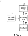
- FIG. 1 is a block diagram showing a handheld electronic device.
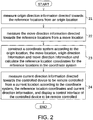
- FIG. 2 is a flowchart of a remote control method.
- FIG. 3 is a schematic diagram showing a handheld electronic device at an origin location.
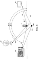
- FIG. 4 is a schematic diagram showing a handheld electronic device moved to a move location from the origin location.
- the handheld electronic device 1 comprises an electronic compass 11, a processing unit 12, a display unit 13 and an input unit 14.
- the handheld electronic device 1 is such as a mobile phone or a tablet PC.
- the display unit 13 and the input unit 14 are, for example, integrated as a touch screen.
- the processing unit 12 couples with the electronic compass 11, the display unit 13 and the input unit 14.
- the remote control method, applicable to the handheld electronic device 1 comprises the following steps.
- these origin direction information ⁇ 1 ⁇ 3 directed towards the controlled devices 31-33 from the origin location U0 are measured by the electronic compass 11.
- the controlled devices 31-33 are correlated with reference locations exemplified by the actual locations of the controlled devices 31-33 in the present embodiment of the invention.
- the aforementioned controlled devices 31-33 are home appliances such as fans, TVs or air conditioners.
- These origin direction information ⁇ 1 ⁇ 3 are such as information of angles.
- three controlled devices are exemplified in the present embodiment of the invention. However, the invention is not limited to such exemplification, and the quantity of the controlled devices may be adjusted according to practical application.
- one reference location may be the actual location of the controlled device while the other reference location may be a particular location of the indoor room.
- the other reference location is a wall corner or a door.
- these move direction information ⁇ 1' ⁇ 3' directed towards the reference locations from the move location U1 are measured by the electronic compass 11.
- These move direction information ⁇ 1' ⁇ 3' are such as information of angles.
- the processing unit 12 defines the distance between the origin location U0 and the move location U1 as a unit length of the coordinate system.
- the unit length of the coordinate system is the length of one stride made by the user.
- the origin location and the move location respectively correspond to the origin coordinate (0,0) and the coordinate (0,1) of the coordinate system.
- the processing unit 23 according to the origin location U0 the move location U1, origin direction information ⁇ 1 ⁇ 3 and the move direction information ⁇ 1' ⁇ 3', constructs the coordinate system and calculates the reference location coordinates for the reference locations in the coordinate system.
- the equation of a straight line may be obtained from the slope of the straight line and any point passing through the straight line. Besides, any two non-parallel straight lines will intersect at one point.
- the slope of the straight line may be obtained from the origin direction information and the move direction information measured by the aforementioned electronic compass 11 for determining the reference location coordinates of the controlled devices 31-33 in the coordinate system.
- the handheld electronic device 1 determines the controlled device to be remote controlled by the user according to the electronic compass 11, the coordinate system and the reference location coordinates.
- step 24 the current direction information directed towards the controlled device to be remote controlled from a current location is measured by the electronic compass 11 according to the coordinate system, the reference location coordinates and the current direction information, and the display unit 13 is controlled by the processing unit 12 to display a control interface of the controlled device to be remote controlled.
- FIG. 5 is a schematic diagram showing a room list.
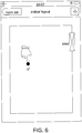
- FIG. 6 is a schematic diagram showing an indoor layout and inputting a current related location.
- FIG. 7 is a schematic diagram showing a control interface.
- FIG. 8 is a schematic diagram showing a handheld electronic device at a current location.
- FIG. 9 is a detailed flowchart of step 24 of remote control method. The step 24 further comprises steps 241-245.
- step 241 an indoor layout of the user's current environment is displayed by the display unit 13.
- the indoor layout illustrated in FIG. 6 is exemplified as being rectangular. However, the invention is not limited to such exemplification, and the indoor layout may be irregular.
- the display unit 13 may display the room list illustrated in FIG. 5 .
- the room list comprises a plurality of options such as a lounge or an office. After the user selects room list option via the input device 14, the display unit 13 displays the indoor layout of the user's current environment as illustrated in FIG. 6 .
- the user may click on the current related location U' roughly within the indoor layout.
- the input unit 14 receives the current related location U' related to the current location.
- the current related location U' inputted by the user may be different from the actual current location U.
- step 243 these candidate direction information ⁇ U',1 , ⁇ U',2 , and ⁇ U',3 that are directed towards the reference location coordinates P1, P2 and P3 from the current related location U' are calculated by the processing unit 12.
- the candidate direction information ⁇ U',1 closest to the current direction information ⁇ U',1 is selected by the processing unit 12 for controlling the display unit 13 to display a control interface of the controlled device to be remote controlled.
- the reference location coordinates of the aforementioned controlled devices 31-33 in the coordinate system are respectively designated by P1 ⁇ P3.
- the candidate direction information ⁇ U',1 is closest to the current direction information ⁇ U',1 .
- the candidate direction information ⁇ U',1 is directed towards the reference location coordinates P1.
- the reference location coordinate P1 is a reference location coordinate of the controlled device 31 in the coordinate system. If the controlled device 31 is a TV, then the processing unit 14, according to the candidate direction information ⁇ U',1 , controls the display unit 13 to display a control interface as illustrated in FIG. 7 .
Landscapes
- Engineering & Computer Science (AREA)
- Human Computer Interaction (AREA)
- Multimedia (AREA)
- Signal Processing (AREA)
- Selective Calling Equipment (AREA)
Description
- The invention relates in general to an electronic device, and more particularly to a handheld electronic device used at the indoor and a remote control method.
- To further increase the convenience of use, more and more home appliances are operated via remote controllers. Through the use of remote controllers, the operations of the home appliances are made more convenient, and the dispositions of the home appliances become more flexible, and there is no need to worry about the problems of manual operation. Meanwhile, each home appliance is equipped with respective remote controller to avoid the mutual interference between different remote controllers. However, the user not only has to carry several remote controllers but also has to remember plenty of corresponding function operations for different devices. The American patent application publication
US 2006/0109143 A1 discloses a portable electronic device and a wireless connection control method. That portable electronic device includes an azimuth detecting section that measures an absolute azimuth of a device main body; a radio communication section that performs radio communication with connection object electronic devices; and a control section that performs control for establishing connection by the radio communication with the connection object electronic devices using the radio communication section, wherein the control section performs control for specifying a connection object to establish connection on the basis of absolute azimuth information detected by the azimuth detecting section and reception information received from the connection object electronic devices by the radio communication section. - The invention is directed to a handheld electronic device and the remote control method. When the user points a controlled device with a handheld electronic device at the indoor, a control interface of the controlled device to be remote controlled is displayed correspondingly.
- According to one embodiment of the present invention, a handheld electronic device is provided. The handheld electronic device comprises a display unit, an electronic compass and a processing unit. The electronic compass measures the origin direction information directed towards at least two reference locations from an origin location and measures the move direction information directed towards the reference locations from a move location. The reference locations are correlated with the controlled device. The processing unit couples with the electronic compass and the display unit. The processing unit, according to the origin location, the move location, the origin direction information and the move direction information, constructs the coordinate system and calculates the reference location coordinates for the reference locations in the coordinate system. After the coordinate system is constructed, the electronic compass measures the current direction information directed towards the controlled device to be remote controlled from a current location. The processing unit controls the display unit to display a control interface of the controlled device to be remote controlled according to the coordinate system, the reference location coordinates and the current direction information.
- According to one alternate embodiment of the present invention, a remote control method. The remote control method is for use in a handheld electronic device. The handheld electronic device comprises a display unit and an electronic compass. The remote control method comprises the following steps. The origin direction information directed towards at least two reference locations from an origin location is measured by an electronic compass. The move direction information directed towards the reference locations from a move location is measured by the electronic compass. According to the origin location, the move location, the origin direction information and the move direction information, a coordinate system is constructed and the reference location coordinates for the reference locations in the coordinate system are calculated. After the coordinate system is constructed, the current direction information directed towards the controlled device to be remote controlled from a current location is measured by the electronic compass according to the coordinate system, the reference location coordinates and the current direction information, and a control interface of the controlled device to be remote controlled is displayed.
- The above and other aspects of the invention will become better understood with regard to the following detailed description of the preferred but non-limiting embodiment(s). The following description is made with reference to the accompanying drawings.
-
-
FIG. 1 is a block diagram showing a handheld electronic device; -
FIG. 2 is a flowchart of a remote control method; -
FIG. 3 is a schematic diagram showing a handheld electronic device at an origin location; -
FIG. 4 is a schematic diagram showing a handheld electronic device moved to a move location from the origin location; -
FIG. 5 is a schematic diagram showing a room list; -
FIG. 6 is a schematic diagram showing an indoor layout and inputting a current related location; -
FIG. 7 is a schematic diagram showing a control interface; -
FIG. 8 is a schematic diagram showing a handheld electronic device at a current location; -
FIG. 9 is a detailed flowchart ofstep 24 of remote control method. - Referring to
FIG. 1 ,FIG. 2 ,FIG. 3 ,FIG. 4 andFIG. 5 .FIG. 1 is a block diagram showing a handheld electronic device.FIG. 2 is a flowchart of a remote control method.FIG. 3 is a schematic diagram showing a handheld electronic device at an origin location.FIG. 4 is a schematic diagram showing a handheld electronic device moved to a move location from the origin location. The handheldelectronic device 1 comprises anelectronic compass 11, aprocessing unit 12, adisplay unit 13 and aninput unit 14. The handheldelectronic device 1 is such as a mobile phone or a tablet PC. Thedisplay unit 13 and theinput unit 14 are, for example, integrated as a touch screen. Theprocessing unit 12 couples with theelectronic compass 11, thedisplay unit 13 and theinput unit 14. When the user holding the handheldelectronic device 1 enters an indoor room such as a bedroom, a lounge or an office, the remote control method, applicable to the handheldelectronic device 1, comprises the following steps. - Firstly, as shown in
step 21, these origin direction information φ1∼φ3 directed towards the controlled devices 31-33 from the origin location U0 are measured by theelectronic compass 11. The controlled devices 31-33 are correlated with reference locations exemplified by the actual locations of the controlled devices 31-33 in the present embodiment of the invention. The aforementioned controlled devices 31-33 are home appliances such as fans, TVs or air conditioners. These origin direction information φ1∼φ3 are such as information of angles. For convenience of elaboration, three controlled devices are exemplified in the present embodiment of the invention. However, the invention is not limited to such exemplification, and the quantity of the controlled devices may be adjusted according to practical application. In addition, when there is only one controlled device disposed at an indoor room, one reference location may be the actual location of the controlled device while the other reference location may be a particular location of the indoor room. For example, the other reference location is a wall corner or a door. - Next, as shown in
step 22, these move direction information φ1'∼φ3' directed towards the reference locations from the move location U1 are measured by theelectronic compass 11. These move direction information φ1'∼φ3' are such as information of angles. Furthermore, after the user holding the handheldelectronic device 1 makes one stride forward, the current location of the handheldelectronic device 1 changes to the move location U1 from the origin location U0. Theprocessing unit 12 defines the distance between the origin location U0 and the move location U1 as a unit length of the coordinate system. In other words, the unit length of the coordinate system is the length of one stride made by the user. Thus, the origin location and the move location respectively correspond to the origin coordinate (0,0) and the coordinate (0,1) of the coordinate system. - Then, as shown in
step 23, theprocessing unit 23, according to the origin location U0 the move location U1, origin direction information φ1∼φ3 and the move direction information φ1'∼φ3', constructs the coordinate system and calculates the reference location coordinates for the reference locations in the coordinate system. The equation of a straight line may be obtained from the slope of the straight line and any point passing through the straight line. Besides, any two non-parallel straight lines will intersect at one point. The slope of the straight line may be obtained from the origin direction information and the move direction information measured by the aforementionedelectronic compass 11 for determining the reference location coordinates of the controlled devices 31-33 in the coordinate system. - After the system coordinates and the reference location coordinates in the coordinate system are constructed according to the steps 21-23, when the user uses the handheld
electronic device 1 for remote-controlling the controlleddevice 31, the controlleddevice 32 or the controlleddevice 33, the handheldelectronic device 1 determines the controlled device to be remote controlled by the user according to theelectronic compass 11, the coordinate system and the reference location coordinates. - Then, as shown in
step 24, the current direction information directed towards the controlled device to be remote controlled from a current location is measured by theelectronic compass 11 according to the coordinate system, the reference location coordinates and the current direction information, and thedisplay unit 13 is controlled by theprocessing unit 12 to display a control interface of the controlled device to be remote controlled. - Referring to
FIG. 5 ,FIG. 6 ,FIG. 7 ,FIG. 8 andFIG. 9 .FIG. 5 is a schematic diagram showing a room list.FIG. 6 is a schematic diagram showing an indoor layout and inputting a current related location.FIG. 7 is a schematic diagram showing a control interface.FIG. 8 is a schematic diagram showing a handheld electronic device at a current location.FIG. 9 is a detailed flowchart ofstep 24 of remote control method. Thestep 24 further comprises steps 241-245. As shown instep 241, an indoor layout of the user's current environment is displayed by thedisplay unit 13. The indoor layout illustrated inFIG. 6 is exemplified as being rectangular. However, the invention is not limited to such exemplification, and the indoor layout may be irregular. Furthermore, thedisplay unit 13 may display the room list illustrated inFIG. 5 . The room list comprises a plurality of options such as a lounge or an office. After the user selects room list option via theinput device 14, thedisplay unit 13 displays the indoor layout of the user's current environment as illustrated inFIG. 6 . - On the indoor layout, the user may click on the current related location U' roughly within the indoor layout. In response to the indoor layout, the
input unit 14 receives the current related location U' related to the current location. The current related location U' inputted by the user may be different from the actual current location U. - Then, as shown in
step 243, these candidate direction information φU',1, φU',2, and φU',3 that are directed towards the reference location coordinates P1, P2 and P3 from the current related location U' are calculated by theprocessing unit 12. - Then, as shown in
step 244, the candidate direction information φU',1 closest to the current direction information φU',1 is selected by theprocessing unit 12 for controlling thedisplay unit 13 to display a control interface of the controlled device to be remote controlled. For example, the reference location coordinates of the aforementioned controlled devices 31-33 in the coordinate system are respectively designated by P1∼P3. The candidate direction information φU',1 is closest to the current direction information φU',1. The candidate direction information φU',1 is directed towards the reference location coordinates P1. The reference location coordinate P1 is a reference location coordinate of the controlleddevice 31 in the coordinate system. If the controlleddevice 31 is a TV, then theprocessing unit 14, according to the candidate direction information φU',1, controls thedisplay unit 13 to display a control interface as illustrated inFIG. 7 .
Claims (14)
- A handheld electronic device (1), comprising:a display unit (13); andan electronic compass (11) for measuring a plurality of origin direction information (φ1, φ2, φ3) directed towards a plurality of reference locations from an origin location (U0), wherein the reference locations are correlated with the controlled device (31, 32, 33),characterized in that the electronic compass (11) is adapted to measure a plurality of move direction information (φ1', φ2', φ3') directed towards the reference locations from a move location (U1); and that the handheld electronic device (1) comprises:a processing unit (12) coupling with the electronic compass (11) and the display unit (13), wherein the processing unit (12) constructs a coordinate system and calculates the reference locations for a plurality of reference location coordinates (P1, P2, P3) in the coordinate system according to the origin location (U0), the move location (U1), the origin direction information (φ1, φ2, φ3) and the move direction information (φ1', φ2', φ3'), wherein after the coordinate system is constructed, the electronic compass (11) measures a current direction information (φU,1, φU,1, φU,3) directed towards the controlled device (31, 32, 33) to be remote controlled from a current location, and the processing unit (12) controls the display unit (13) to display a control interface of the controlled device (31, 32, 33) to be remote controlled according to the coordinate system, the reference location coordinates (P1, P2, P3) and the current direction information (φU,1, φU,1, φU',1).
- The handheld electronic device (1) according to claim 1, further comprising:an input unit (14) coupling with the processing unit (12) for receiving a current related location (U') related to the current location in response to an indoor layout;wherein the display unit (13) further displays an indoor layout of the current environment.
- The handheld electronic device (1) according to claim 2, wherein the processing unit (12) calculates a plurality of candidate direction information (φU',1,φU',2, φU',3) directed towards the reference location coordinates (P1, P2, P3) from the current related location (U'), and selects the candidate direction information (φU',1, φU',2, φU',3) closest to the current direction information (φU,1, φU,2 φU,3) for controlling the display unit (13) to display a control interface of the controlled device (31, 32, 33) to be remote controlled.
- The handheld electronic device (1) according to claim 2, wherein the indoor layout is rectangular.
- The handheld electronic device (1) according to claim 2, wherein the indoor layout is irregular.
- The handheld electronic device (1) according to claim 1, wherein the distance between the origin location (U0) and the move location (U1) is defined as a unit length of the coordinate system.
- The handheld electronic device (1) according to claim 6, wherein the unit length of coordinate system is the length of one stride made by the user.
- A remote control method for use in a handheld electronic device (1), wherein the handheld electronic device (1) comprises a display unit (13) and an electronic compass (11), and the remote control method comprises:(21) measuring a plurality of origin direction information (φ1, φ2, φ3) directed towards a plurality of reference locations from an origin location (U0) by the electronic compass (11), wherein the reference locations are correlated with the controlled device (31, 32, 33);characterized in that the remote control method comprises:(22) measuring a plurality of move direction information (φ1', φ2', φ3') directed towards the reference locations from a move location (U1) by the electronic compass (11);(23) constructing a coordinate system and calculating a plurality of reference location coordinates (P1, P2, P3) for the reference locations in the coordinate system according to the origin location (U0), the move location (U1), these origin direction information (φ1, φ2, φ3) and these move direction information (φ1', φ2', φ3'); and(24) measuring a current direction information (φU,1, φU,2, φU,3) directed towards the controlled device (31, 32, 33) to be remote controlled from a current location by the electronic compass (11) and displaying a control interface of the controlled device (31, 32, 33) to be remote controlled according to the coordinate system, the reference location coordinates (P1, P2, P3) and the current direction information (φU,1, φU,2, φU,3) after the coordinate system is constructed.
- The remote control method according to claim 8, further comprising:(241) displaying an indoor layout of the current environment; and(242) receiving a current related location (U') related to the current location in response to the indoor layout.
- The remote control method according to claim 9, further comprising:(243) calculating a plurality of candidate direction information (φU',1, φU',2, φU',3) directed towards the reference location coordinates (P1, P2, P3) from the current related location (U'); and(244) selecting the candidate direction information (φU',1, φU',2, φU',3) closest to the current direction information (φU,1, φU,2, φU,3) for controlling the display unit (13) to display a control interface of the controlled device (31, 32, 33) to be remote controlled.
- The remote control method according to claim 9, wherein the indoor layout is rectangular.
- The remote control method according to claim 9, wherein the indoor layout is irregular.
- The remote control method according to claim 8, wherein the distance between the origin location (U0) and the move location (U1) is defined as a unit length of the coordinate system.
- The remote control method according to claim 13, wherein the unit length of the coordinate system is the length of one stride made by the user.
Applications Claiming Priority (1)
| Application Number | Priority Date | Filing Date | Title |
|---|---|---|---|
| TW100143811A TWI434519B (en) | 2011-11-29 | 2011-11-29 | Handheld electronic device and handheld communication remote control method |
Publications (3)
| Publication Number | Publication Date |
|---|---|
| EP2600629A2 EP2600629A2 (en) | 2013-06-05 |
| EP2600629A3 EP2600629A3 (en) | 2013-07-24 |
| EP2600629B1 true EP2600629B1 (en) | 2017-09-06 |
Family
ID=46245837
Family Applications (1)
| Application Number | Title | Priority Date | Filing Date |
|---|---|---|---|
| EP12169641.3A Not-in-force EP2600629B1 (en) | 2011-11-29 | 2012-05-25 | Handheld electronic device and remote control method |
Country Status (3)
| Country | Link |
|---|---|
| US (1) | US9071862B2 (en) |
| EP (1) | EP2600629B1 (en) |
| TW (1) | TWI434519B (en) |
Families Citing this family (3)
| Publication number | Priority date | Publication date | Assignee | Title |
|---|---|---|---|---|
| US11334037B2 (en) * | 2013-03-01 | 2022-05-17 | Comcast Cable Communications, Llc | Systems and methods for controlling devices |
| TWI525474B (en) | 2014-01-29 | 2016-03-11 | 緯創資通股份有限公司 | Handheld electronic apparatus, remote control method, home appliance system and home appliance apparatus |
| KR20150104711A (en) * | 2014-03-06 | 2015-09-16 | 엘지전자 주식회사 | Video display device and operating method thereof |
Family Cites Families (8)
| Publication number | Priority date | Publication date | Assignee | Title |
|---|---|---|---|---|
| US5043646A (en) | 1990-05-01 | 1991-08-27 | Smith Engineering | Remote control direction selecting system |
| SG114479A1 (en) | 2000-11-27 | 2005-09-28 | Ibm | Selecting a target device in a device network |
| US6516271B2 (en) | 2001-06-29 | 2003-02-04 | The Regents Of The University Of California | Method and apparatus for ultra precise GPS-based mapping of seeds or vegetation during planting |
| JP4111165B2 (en) | 2004-05-07 | 2008-07-02 | ソニー株式会社 | Portable electronic device, wireless communication system and wireless connection control method thereof |
| US8326533B2 (en) | 2010-01-21 | 2012-12-04 | Invensense, Inc. | Apparatus and methodology for calibration of a gyroscope and a compass included in a handheld device |
| JP2011193426A (en) | 2010-03-15 | 2011-09-29 | Shinten Sangyo Co Ltd | Mobile phone terminal with remote control function |
| US9109877B2 (en) * | 2010-05-21 | 2015-08-18 | Jonathan S. Thierman | Method and apparatus for dimensional measurement |
| US8717579B2 (en) * | 2011-04-20 | 2014-05-06 | Thomas E. Portegys | Distance measuring device using a method of spanning separately targeted endpoints |
-
2011
- 2011-11-29 TW TW100143811A patent/TWI434519B/en not_active IP Right Cessation
-
2012
- 2012-04-09 US US13/442,149 patent/US9071862B2/en not_active Expired - Fee Related
- 2012-05-25 EP EP12169641.3A patent/EP2600629B1/en not_active Not-in-force
Non-Patent Citations (1)
| Title |
|---|
| None * |
Also Published As
| Publication number | Publication date |
|---|---|
| EP2600629A2 (en) | 2013-06-05 |
| TW201322650A (en) | 2013-06-01 |
| US9071862B2 (en) | 2015-06-30 |
| EP2600629A3 (en) | 2013-07-24 |
| US20130137466A1 (en) | 2013-05-30 |
| TWI434519B (en) | 2014-04-11 |
Similar Documents
| Publication | Publication Date | Title |
|---|---|---|
| KR102071575B1 (en) | Moving robot, user terminal apparatus, and control method thereof | |
| JP4281400B2 (en) | COMMUNICATION DEVICE, ITS DISPLAY METHOD, COMPUTER PROGRAM, AND COMMUNICATION METHOD | |
| US9453732B2 (en) | Remote control for sensing movement, image display apparatus for controlling pointer by the remote control, and controlling method thereof | |
| CN103152467B (en) | Handheld electronic device and remote control method | |
| US20160334125A1 (en) | Customized control method and system for air conditioner operation mode | |
| JP5646018B1 (en) | Installation location development support method, terminal device, installation location development support system, and program | |
| JP2015133088A5 (en) | ||
| JPWO2012101762A1 (en) | Control device, air conditioning system, control method and program | |
| TW201503703A (en) | Electrical appliances controlling system and method | |
| KR101473771B1 (en) | ELECTRONIC DEVICE, CONTROL METHOD OF THE ELECTRONIC DEVICE, AND REMOTE CONTROL DEVICE AND CONTROL METHOD | |
| EP2451122A2 (en) | Mobile device and control method thereof | |
| KR20170091426A (en) | Display apparatus and control method thereof | |
| EP3659334B1 (en) | Universal remote control of devices based on orientation of remote | |
| US9071862B2 (en) | Handheld electronic device and remote control method | |
| CN111127863A (en) | Control method of device, remote controller and storage medium | |
| KR20110128096A (en) | Augmented Reality Realization System Using Building Environment Information and Its Method | |
| CN106383458B (en) | Universal wireless control method and system for electrical equipment | |
| JP6049494B2 (en) | Mobile device | |
| JP2020038046A (en) | Terminal device, program, and air conditioning system | |
| JP2019020097A (en) | Air conditioner system | |
| JP2014164346A5 (en) | Device management system and portable terminal | |
| US10518405B2 (en) | Industrial robot system comprising a dual arm robot | |
| JP2014128006A (en) | Electronic apparatus, apparatus control method and apparatus control program | |
| KR20160009852A (en) | Elevator calling system | |
| KR100702808B1 (en) | Object recognition system and method using a portable terminal |
Legal Events
| Date | Code | Title | Description |
|---|---|---|---|
| PUAI | Public reference made under article 153(3) epc to a published international application that has entered the european phase |
Free format text: ORIGINAL CODE: 0009012 |
|
| AK | Designated contracting states |
Kind code of ref document: A2 Designated state(s): AL AT BE BG CH CY CZ DE DK EE ES FI FR GB GR HR HU IE IS IT LI LT LU LV MC MK MT NL NO PL PT RO RS SE SI SK SM TR |
|
| AX | Request for extension of the european patent |
Extension state: BA ME |
|
| PUAL | Search report despatched |
Free format text: ORIGINAL CODE: 0009013 |
|
| AK | Designated contracting states |
Kind code of ref document: A3 Designated state(s): AL AT BE BG CH CY CZ DE DK EE ES FI FR GB GR HR HU IE IS IT LI LT LU LV MC MK MT NL NO PL PT RO RS SE SI SK SM TR |
|
| AX | Request for extension of the european patent |
Extension state: BA ME |
|
| RIC1 | Information provided on ipc code assigned before grant |
Ipc: H04N 21/422 20110101AFI20130620BHEP |
|
| 17P | Request for examination filed |
Effective date: 20131014 |
|
| RBV | Designated contracting states (corrected) |
Designated state(s): AL AT BE BG CH CY CZ DE DK EE ES FI FR GB GR HR HU IE IS IT LI LT LU LV MC MK MT NL NO PL PT RO RS SE SI SK SM TR |
|
| GRAP | Despatch of communication of intention to grant a patent |
Free format text: ORIGINAL CODE: EPIDOSNIGR1 |
|
| INTG | Intention to grant announced |
Effective date: 20170327 |
|
| GRAS | Grant fee paid |
Free format text: ORIGINAL CODE: EPIDOSNIGR3 |
|
| GRAA | (expected) grant |
Free format text: ORIGINAL CODE: 0009210 |
|
| AK | Designated contracting states |
Kind code of ref document: B1 Designated state(s): AL AT BE BG CH CY CZ DE DK EE ES FI FR GB GR HR HU IE IS IT LI LT LU LV MC MK MT NL NO PL PT RO RS SE SI SK SM TR |
|
| REG | Reference to a national code |
Ref country code: GB Ref legal event code: FG4D |
|
| REG | Reference to a national code |
Ref country code: CH Ref legal event code: EP Ref country code: AT Ref legal event code: REF Ref document number: 927076 Country of ref document: AT Kind code of ref document: T Effective date: 20170915 |
|
| REG | Reference to a national code |
Ref country code: IE Ref legal event code: FG4D |
|
| REG | Reference to a national code |
Ref country code: DE Ref legal event code: R096 Ref document number: 602012036845 Country of ref document: DE |
|
| REG | Reference to a national code |
Ref country code: NL Ref legal event code: MP Effective date: 20170906 |
|
| REG | Reference to a national code |
Ref country code: LT Ref legal event code: MG4D |
|
| PG25 | Lapsed in a contracting state [announced via postgrant information from national office to epo] |
Ref country code: SE Free format text: LAPSE BECAUSE OF FAILURE TO SUBMIT A TRANSLATION OF THE DESCRIPTION OR TO PAY THE FEE WITHIN THE PRESCRIBED TIME-LIMIT Effective date: 20170906 Ref country code: FI Free format text: LAPSE BECAUSE OF FAILURE TO SUBMIT A TRANSLATION OF THE DESCRIPTION OR TO PAY THE FEE WITHIN THE PRESCRIBED TIME-LIMIT Effective date: 20170906 Ref country code: LT Free format text: LAPSE BECAUSE OF FAILURE TO SUBMIT A TRANSLATION OF THE DESCRIPTION OR TO PAY THE FEE WITHIN THE PRESCRIBED TIME-LIMIT Effective date: 20170906 Ref country code: NO Free format text: LAPSE BECAUSE OF FAILURE TO SUBMIT A TRANSLATION OF THE DESCRIPTION OR TO PAY THE FEE WITHIN THE PRESCRIBED TIME-LIMIT Effective date: 20171206 Ref country code: HR Free format text: LAPSE BECAUSE OF FAILURE TO SUBMIT A TRANSLATION OF THE DESCRIPTION OR TO PAY THE FEE WITHIN THE PRESCRIBED TIME-LIMIT Effective date: 20170906 |
|
| REG | Reference to a national code |
Ref country code: AT Ref legal event code: MK05 Ref document number: 927076 Country of ref document: AT Kind code of ref document: T Effective date: 20170906 |
|
| PG25 | Lapsed in a contracting state [announced via postgrant information from national office to epo] |
Ref country code: GR Free format text: LAPSE BECAUSE OF FAILURE TO SUBMIT A TRANSLATION OF THE DESCRIPTION OR TO PAY THE FEE WITHIN THE PRESCRIBED TIME-LIMIT Effective date: 20171207 Ref country code: RS Free format text: LAPSE BECAUSE OF FAILURE TO SUBMIT A TRANSLATION OF THE DESCRIPTION OR TO PAY THE FEE WITHIN THE PRESCRIBED TIME-LIMIT Effective date: 20170906 Ref country code: BG Free format text: LAPSE BECAUSE OF FAILURE TO SUBMIT A TRANSLATION OF THE DESCRIPTION OR TO PAY THE FEE WITHIN THE PRESCRIBED TIME-LIMIT Effective date: 20171206 Ref country code: ES Free format text: LAPSE BECAUSE OF FAILURE TO SUBMIT A TRANSLATION OF THE DESCRIPTION OR TO PAY THE FEE WITHIN THE PRESCRIBED TIME-LIMIT Effective date: 20170906 Ref country code: LV Free format text: LAPSE BECAUSE OF FAILURE TO SUBMIT A TRANSLATION OF THE DESCRIPTION OR TO PAY THE FEE WITHIN THE PRESCRIBED TIME-LIMIT Effective date: 20170906 |
|
| PG25 | Lapsed in a contracting state [announced via postgrant information from national office to epo] |
Ref country code: NL Free format text: LAPSE BECAUSE OF FAILURE TO SUBMIT A TRANSLATION OF THE DESCRIPTION OR TO PAY THE FEE WITHIN THE PRESCRIBED TIME-LIMIT Effective date: 20170906 |
|
| PG25 | Lapsed in a contracting state [announced via postgrant information from national office to epo] |
Ref country code: CZ Free format text: LAPSE BECAUSE OF FAILURE TO SUBMIT A TRANSLATION OF THE DESCRIPTION OR TO PAY THE FEE WITHIN THE PRESCRIBED TIME-LIMIT Effective date: 20170906 Ref country code: PL Free format text: LAPSE BECAUSE OF FAILURE TO SUBMIT A TRANSLATION OF THE DESCRIPTION OR TO PAY THE FEE WITHIN THE PRESCRIBED TIME-LIMIT Effective date: 20170906 Ref country code: RO Free format text: LAPSE BECAUSE OF FAILURE TO SUBMIT A TRANSLATION OF THE DESCRIPTION OR TO PAY THE FEE WITHIN THE PRESCRIBED TIME-LIMIT Effective date: 20170906 |
|
| REG | Reference to a national code |
Ref country code: FR Ref legal event code: PLFP Year of fee payment: 7 |
|
| PG25 | Lapsed in a contracting state [announced via postgrant information from national office to epo] |
Ref country code: EE Free format text: LAPSE BECAUSE OF FAILURE TO SUBMIT A TRANSLATION OF THE DESCRIPTION OR TO PAY THE FEE WITHIN THE PRESCRIBED TIME-LIMIT Effective date: 20170906 Ref country code: IT Free format text: LAPSE BECAUSE OF FAILURE TO SUBMIT A TRANSLATION OF THE DESCRIPTION OR TO PAY THE FEE WITHIN THE PRESCRIBED TIME-LIMIT Effective date: 20170906 Ref country code: AT Free format text: LAPSE BECAUSE OF FAILURE TO SUBMIT A TRANSLATION OF THE DESCRIPTION OR TO PAY THE FEE WITHIN THE PRESCRIBED TIME-LIMIT Effective date: 20170906 Ref country code: IS Free format text: LAPSE BECAUSE OF FAILURE TO SUBMIT A TRANSLATION OF THE DESCRIPTION OR TO PAY THE FEE WITHIN THE PRESCRIBED TIME-LIMIT Effective date: 20180106 Ref country code: SK Free format text: LAPSE BECAUSE OF FAILURE TO SUBMIT A TRANSLATION OF THE DESCRIPTION OR TO PAY THE FEE WITHIN THE PRESCRIBED TIME-LIMIT Effective date: 20170906 Ref country code: SM Free format text: LAPSE BECAUSE OF FAILURE TO SUBMIT A TRANSLATION OF THE DESCRIPTION OR TO PAY THE FEE WITHIN THE PRESCRIBED TIME-LIMIT Effective date: 20170906 |
|
| REG | Reference to a national code |
Ref country code: DE Ref legal event code: R097 Ref document number: 602012036845 Country of ref document: DE |
|
| PLBE | No opposition filed within time limit |
Free format text: ORIGINAL CODE: 0009261 |
|
| STAA | Information on the status of an ep patent application or granted ep patent |
Free format text: STATUS: NO OPPOSITION FILED WITHIN TIME LIMIT |
|
| PG25 | Lapsed in a contracting state [announced via postgrant information from national office to epo] |
Ref country code: DK Free format text: LAPSE BECAUSE OF FAILURE TO SUBMIT A TRANSLATION OF THE DESCRIPTION OR TO PAY THE FEE WITHIN THE PRESCRIBED TIME-LIMIT Effective date: 20170906 |
|
| PGFP | Annual fee paid to national office [announced via postgrant information from national office to epo] |
Ref country code: DE Payment date: 20180529 Year of fee payment: 7 |
|
| 26N | No opposition filed |
Effective date: 20180607 |
|
| PG25 | Lapsed in a contracting state [announced via postgrant information from national office to epo] |
Ref country code: SI Free format text: LAPSE BECAUSE OF FAILURE TO SUBMIT A TRANSLATION OF THE DESCRIPTION OR TO PAY THE FEE WITHIN THE PRESCRIBED TIME-LIMIT Effective date: 20170906 |
|
| PGFP | Annual fee paid to national office [announced via postgrant information from national office to epo] |
Ref country code: FR Payment date: 20180525 Year of fee payment: 7 |
|
| PGFP | Annual fee paid to national office [announced via postgrant information from national office to epo] |
Ref country code: GB Payment date: 20180529 Year of fee payment: 7 |
|
| REG | Reference to a national code |
Ref country code: CH Ref legal event code: PL |
|
| REG | Reference to a national code |
Ref country code: BE Ref legal event code: MM Effective date: 20180531 |
|
| PG25 | Lapsed in a contracting state [announced via postgrant information from national office to epo] |
Ref country code: MC Free format text: LAPSE BECAUSE OF FAILURE TO SUBMIT A TRANSLATION OF THE DESCRIPTION OR TO PAY THE FEE WITHIN THE PRESCRIBED TIME-LIMIT Effective date: 20170906 |
|
| REG | Reference to a national code |
Ref country code: IE Ref legal event code: MM4A |
|
| PG25 | Lapsed in a contracting state [announced via postgrant information from national office to epo] |
Ref country code: LI Free format text: LAPSE BECAUSE OF NON-PAYMENT OF DUE FEES Effective date: 20180531 Ref country code: CH Free format text: LAPSE BECAUSE OF NON-PAYMENT OF DUE FEES Effective date: 20180531 |
|
| PG25 | Lapsed in a contracting state [announced via postgrant information from national office to epo] |
Ref country code: LU Free format text: LAPSE BECAUSE OF NON-PAYMENT OF DUE FEES Effective date: 20180525 |
|
| PG25 | Lapsed in a contracting state [announced via postgrant information from national office to epo] |
Ref country code: IE Free format text: LAPSE BECAUSE OF NON-PAYMENT OF DUE FEES Effective date: 20180525 |
|
| PG25 | Lapsed in a contracting state [announced via postgrant information from national office to epo] |
Ref country code: BE Free format text: LAPSE BECAUSE OF NON-PAYMENT OF DUE FEES Effective date: 20180531 |
|
| REG | Reference to a national code |
Ref country code: DE Ref legal event code: R119 Ref document number: 602012036845 Country of ref document: DE |
|
| GBPC | Gb: european patent ceased through non-payment of renewal fee |
Effective date: 20190525 |
|
| PG25 | Lapsed in a contracting state [announced via postgrant information from national office to epo] |
Ref country code: MT Free format text: LAPSE BECAUSE OF NON-PAYMENT OF DUE FEES Effective date: 20180525 |
|
| PG25 | Lapsed in a contracting state [announced via postgrant information from national office to epo] |
Ref country code: TR Free format text: LAPSE BECAUSE OF FAILURE TO SUBMIT A TRANSLATION OF THE DESCRIPTION OR TO PAY THE FEE WITHIN THE PRESCRIBED TIME-LIMIT Effective date: 20170906 |
|
| PG25 | Lapsed in a contracting state [announced via postgrant information from national office to epo] |
Ref country code: GB Free format text: LAPSE BECAUSE OF NON-PAYMENT OF DUE FEES Effective date: 20190525 Ref country code: DE Free format text: LAPSE BECAUSE OF NON-PAYMENT OF DUE FEES Effective date: 20191203 |
|
| PG25 | Lapsed in a contracting state [announced via postgrant information from national office to epo] |
Ref country code: HU Free format text: LAPSE BECAUSE OF FAILURE TO SUBMIT A TRANSLATION OF THE DESCRIPTION OR TO PAY THE FEE WITHIN THE PRESCRIBED TIME-LIMIT; INVALID AB INITIO Effective date: 20120525 Ref country code: PT Free format text: LAPSE BECAUSE OF FAILURE TO SUBMIT A TRANSLATION OF THE DESCRIPTION OR TO PAY THE FEE WITHIN THE PRESCRIBED TIME-LIMIT Effective date: 20170906 |
|
| PG25 | Lapsed in a contracting state [announced via postgrant information from national office to epo] |
Ref country code: CY Free format text: LAPSE BECAUSE OF FAILURE TO SUBMIT A TRANSLATION OF THE DESCRIPTION OR TO PAY THE FEE WITHIN THE PRESCRIBED TIME-LIMIT Effective date: 20170906 Ref country code: FR Free format text: LAPSE BECAUSE OF NON-PAYMENT OF DUE FEES Effective date: 20190531 Ref country code: MK Free format text: LAPSE BECAUSE OF NON-PAYMENT OF DUE FEES Effective date: 20170906 |
|
| PG25 | Lapsed in a contracting state [announced via postgrant information from national office to epo] |
Ref country code: AL Free format text: LAPSE BECAUSE OF FAILURE TO SUBMIT A TRANSLATION OF THE DESCRIPTION OR TO PAY THE FEE WITHIN THE PRESCRIBED TIME-LIMIT Effective date: 20170906 |