EP2600549A2 - Procédé et dispositif de transmission d'informations de commande - Google Patents
Procédé et dispositif de transmission d'informations de commande Download PDFInfo
- Publication number
- EP2600549A2 EP2600549A2 EP11812746.3A EP11812746A EP2600549A2 EP 2600549 A2 EP2600549 A2 EP 2600549A2 EP 11812746 A EP11812746 A EP 11812746A EP 2600549 A2 EP2600549 A2 EP 2600549A2
- Authority
- EP
- European Patent Office
- Prior art keywords
- nack
- ack
- pucch
- subframe
- pdcch
- Prior art date
- Legal status (The legal status is an assumption and is not a legal conclusion. Google has not performed a legal analysis and makes no representation as to the accuracy of the status listed.)
- Granted
Links
- 238000000034 method Methods 0.000 title claims abstract description 45
- 230000004044 response Effects 0.000 claims abstract description 34
- 238000004891 communication Methods 0.000 claims abstract description 29
- 230000011664 signaling Effects 0.000 claims abstract description 21
- 230000001960 triggered effect Effects 0.000 claims description 3
- 230000005540 biological transmission Effects 0.000 description 82
- 230000002776 aggregation Effects 0.000 description 12
- 238000004220 aggregation Methods 0.000 description 12
- 238000012544 monitoring process Methods 0.000 description 10
- 238000013507 mapping Methods 0.000 description 7
- 239000000470 constituent Substances 0.000 description 5
- 238000013468 resource allocation Methods 0.000 description 5
- 230000007480 spreading Effects 0.000 description 5
- 125000004122 cyclic group Chemical group 0.000 description 4
- 238000005516 engineering process Methods 0.000 description 4
- 230000008569 process Effects 0.000 description 3
- 101150071746 Pbsn gene Proteins 0.000 description 2
- 230000004913 activation Effects 0.000 description 2
- 230000004931 aggregating effect Effects 0.000 description 2
- 239000000969 carrier Substances 0.000 description 2
- 238000010276 construction Methods 0.000 description 2
- 230000000694 effects Effects 0.000 description 2
- 230000006870 function Effects 0.000 description 2
- 238000012986 modification Methods 0.000 description 2
- 230000004048 modification Effects 0.000 description 2
- 241000760358 Enodes Species 0.000 description 1
- 108010003272 Hyaluronate lyase Proteins 0.000 description 1
- 238000003491 array Methods 0.000 description 1
- 230000015556 catabolic process Effects 0.000 description 1
- 230000001427 coherent effect Effects 0.000 description 1
- 238000007796 conventional method Methods 0.000 description 1
- 238000006731 degradation reaction Methods 0.000 description 1
- 230000001419 dependent effect Effects 0.000 description 1
- 238000013461 design Methods 0.000 description 1
- 238000001514 detection method Methods 0.000 description 1
- 238000010586 diagram Methods 0.000 description 1
- GVVPGTZRZFNKDS-JXMROGBWSA-N geranyl diphosphate Chemical compound CC(C)=CCC\C(C)=C\CO[P@](O)(=O)OP(O)(O)=O GVVPGTZRZFNKDS-JXMROGBWSA-N 0.000 description 1
- PCHJSUWPFVWCPO-UHFFFAOYSA-N gold Chemical group [Au] PCHJSUWPFVWCPO-UHFFFAOYSA-N 0.000 description 1
- 230000007774 longterm Effects 0.000 description 1
- 239000011159 matrix material Substances 0.000 description 1
- 238000010295 mobile communication Methods 0.000 description 1
- 230000000737 periodic effect Effects 0.000 description 1
- 230000010363 phase shift Effects 0.000 description 1
- 238000012545 processing Methods 0.000 description 1
- 230000008054 signal transmission Effects 0.000 description 1
- 235000015096 spirit Nutrition 0.000 description 1
Images


Classifications
-
- H—ELECTRICITY
- H04—ELECTRIC COMMUNICATION TECHNIQUE
- H04L—TRANSMISSION OF DIGITAL INFORMATION, e.g. TELEGRAPHIC COMMUNICATION
- H04L1/00—Arrangements for detecting or preventing errors in the information received
- H04L1/0001—Systems modifying transmission characteristics according to link quality, e.g. power backoff
- H04L1/0023—Systems modifying transmission characteristics according to link quality, e.g. power backoff characterised by the signalling
- H04L1/0027—Scheduling of signalling, e.g. occurrence thereof
-
- H—ELECTRICITY
- H04—ELECTRIC COMMUNICATION TECHNIQUE
- H04L—TRANSMISSION OF DIGITAL INFORMATION, e.g. TELEGRAPHIC COMMUNICATION
- H04L1/00—Arrangements for detecting or preventing errors in the information received
- H04L1/12—Arrangements for detecting or preventing errors in the information received by using return channel
- H04L1/16—Arrangements for detecting or preventing errors in the information received by using return channel in which the return channel carries supervisory signals, e.g. repetition request signals
- H04L1/1607—Details of the supervisory signal
- H04L1/1671—Details of the supervisory signal the supervisory signal being transmitted together with control information
-
- H—ELECTRICITY
- H04—ELECTRIC COMMUNICATION TECHNIQUE
- H04L—TRANSMISSION OF DIGITAL INFORMATION, e.g. TELEGRAPHIC COMMUNICATION
- H04L1/00—Arrangements for detecting or preventing errors in the information received
- H04L1/12—Arrangements for detecting or preventing errors in the information received by using return channel
- H04L1/16—Arrangements for detecting or preventing errors in the information received by using return channel in which the return channel carries supervisory signals, e.g. repetition request signals
- H04L1/18—Automatic repetition systems, e.g. Van Duuren systems
- H04L1/1867—Arrangements specially adapted for the transmitter end
- H04L1/1887—Scheduling and prioritising arrangements
-
- H—ELECTRICITY
- H04—ELECTRIC COMMUNICATION TECHNIQUE
- H04L—TRANSMISSION OF DIGITAL INFORMATION, e.g. TELEGRAPHIC COMMUNICATION
- H04L5/00—Arrangements affording multiple use of the transmission path
-
- H—ELECTRICITY
- H04—ELECTRIC COMMUNICATION TECHNIQUE
- H04L—TRANSMISSION OF DIGITAL INFORMATION, e.g. TELEGRAPHIC COMMUNICATION
- H04L5/00—Arrangements affording multiple use of the transmission path
- H04L5/003—Arrangements for allocating sub-channels of the transmission path
- H04L5/0032—Distributed allocation, i.e. involving a plurality of allocating devices, each making partial allocation
-
- H—ELECTRICITY
- H04—ELECTRIC COMMUNICATION TECHNIQUE
- H04L—TRANSMISSION OF DIGITAL INFORMATION, e.g. TELEGRAPHIC COMMUNICATION
- H04L5/00—Arrangements affording multiple use of the transmission path
- H04L5/003—Arrangements for allocating sub-channels of the transmission path
- H04L5/0053—Allocation of signaling, i.e. of overhead other than pilot signals
- H04L5/0055—Physical resource allocation for ACK/NACK
-
- H—ELECTRICITY
- H04—ELECTRIC COMMUNICATION TECHNIQUE
- H04W—WIRELESS COMMUNICATION NETWORKS
- H04W72/00—Local resource management
- H04W72/20—Control channels or signalling for resource management
-
- H—ELECTRICITY
- H04—ELECTRIC COMMUNICATION TECHNIQUE
- H04W—WIRELESS COMMUNICATION NETWORKS
- H04W72/00—Local resource management
- H04W72/20—Control channels or signalling for resource management
- H04W72/21—Control channels or signalling for resource management in the uplink direction of a wireless link, i.e. towards the network
-
- H—ELECTRICITY
- H04—ELECTRIC COMMUNICATION TECHNIQUE
- H04W—WIRELESS COMMUNICATION NETWORKS
- H04W72/00—Local resource management
- H04W72/20—Control channels or signalling for resource management
- H04W72/23—Control channels or signalling for resource management in the downlink direction of a wireless link, i.e. towards a terminal
-
- H—ELECTRICITY
- H04—ELECTRIC COMMUNICATION TECHNIQUE
- H04L—TRANSMISSION OF DIGITAL INFORMATION, e.g. TELEGRAPHIC COMMUNICATION
- H04L1/00—Arrangements for detecting or preventing errors in the information received
- H04L1/0001—Systems modifying transmission characteristics according to link quality, e.g. power backoff
- H04L1/0023—Systems modifying transmission characteristics according to link quality, e.g. power backoff characterised by the signalling
- H04L1/0026—Transmission of channel quality indication
-
- H—ELECTRICITY
- H04—ELECTRIC COMMUNICATION TECHNIQUE
- H04L—TRANSMISSION OF DIGITAL INFORMATION, e.g. TELEGRAPHIC COMMUNICATION
- H04L1/00—Arrangements for detecting or preventing errors in the information received
- H04L1/0001—Systems modifying transmission characteristics according to link quality, e.g. power backoff
- H04L1/0023—Systems modifying transmission characteristics according to link quality, e.g. power backoff characterised by the signalling
- H04L1/0028—Formatting
-
- H—ELECTRICITY
- H04—ELECTRIC COMMUNICATION TECHNIQUE
- H04L—TRANSMISSION OF DIGITAL INFORMATION, e.g. TELEGRAPHIC COMMUNICATION
- H04L1/00—Arrangements for detecting or preventing errors in the information received
- H04L1/004—Arrangements for detecting or preventing errors in the information received by using forward error control
- H04L1/0056—Systems characterized by the type of code used
- H04L1/0067—Rate matching
- H04L1/0068—Rate matching by puncturing
-
- H—ELECTRICITY
- H04—ELECTRIC COMMUNICATION TECHNIQUE
- H04L—TRANSMISSION OF DIGITAL INFORMATION, e.g. TELEGRAPHIC COMMUNICATION
- H04L1/00—Arrangements for detecting or preventing errors in the information received
- H04L1/004—Arrangements for detecting or preventing errors in the information received by using forward error control
- H04L1/0072—Error control for data other than payload data, e.g. control data
-
- H—ELECTRICITY
- H04—ELECTRIC COMMUNICATION TECHNIQUE
- H04L—TRANSMISSION OF DIGITAL INFORMATION, e.g. TELEGRAPHIC COMMUNICATION
- H04L5/00—Arrangements affording multiple use of the transmission path
- H04L5/0001—Arrangements for dividing the transmission path
- H04L5/0003—Two-dimensional division
- H04L5/0005—Time-frequency
- H04L5/0007—Time-frequency the frequencies being orthogonal, e.g. OFDM(A), DMT
- H04L5/001—Time-frequency the frequencies being orthogonal, e.g. OFDM(A), DMT the frequencies being arranged in component carriers
Definitions
- the present invention relates to a wireless communication system, and more particularly, to a method and apparatus for transmitting control information.
- a wireless communication system is a multiple access system capable of supporting communication with multiple users by sharing available system resources (bandwidth, transmit power, etc.).
- the multiple access system includes, for example, a Code Division Multiple Access (CDMA) system, a Frequency Division Multiple Access (FDMA) system, a Time Division Multiple Access (TDMA) system, an Orthogonal Frequency Division Multiple Access (OFDMA) system, a Single Carrier Frequency Division Multiple Access (SC-FDMA) system, and the like.
- CDMA Code Division Multiple Access
- FDMA Frequency Division Multiple Access
- TDMA Time Division Multiple Access
- OFDMA Orthogonal Frequency Division Multiple Access
- SC-FDMA Single Carrier Frequency Division Multiple Access
- An object of the present invention is to provide a method and apparatus for efficiently transmitting control information in a wireless communication system.
- Another object of the present invention is to provide a method and apparatus for efficiently transmitting uplink control information in a situation in which a plurality of cells is configured and efficiently managing resources for transmission of the uplink control information.
- a method for transmitting uplink control information in a situation in which a plurality of cells including a Primary Cell (PCell) and a Secondary Cell (SCell) is configured in a wireless communication system includes receiving one or more Physical Downlink Control Channels (PDCCHs); generating reception response information corresponding to the one or more PDCCHs; and transmitting the reception response information on a subframe through a Physical Uplink Control Channel (PUCCH), wherein, if only one PCell PDCCH is detected and a prescribed condition is satisfied, the reception response information is transmitted using a PUCCH resource pre-configured by a higher-layer signaling, and if only one PCell PDCCH is detected and a prescribed condition is not satisfied, the reception response information is transmitted using a PUCCH resource linked with an index of a resource constituting the PCell PDCCH.
- PUCCHs Physical Downlink Control Channels
- PUCCH Physical Uplink Control Channel
- a communication apparatus configured to transmit uplink control information in a situation in which a plurality of cells including a Primary Cell (PCell) and a Secondary Cell (SCell) is configured in a wireless communication system
- a Radio Frequency (RF) unit includes a Radio Frequency (RF) unit; and a processor, wherein the processor is configured to receive one or more Physical Downlink Control Channels (PDCCHs), generate reception response information corresponding to the one or more PDCCHs, and transmit the reception response information on a subframe through a Physical Uplink Control Channel (PUCCH), and wherein, if only one PCell PDCCH is detected and a prescribed condition is satisfied, the reception response information is transmitted using a PUCCH resource pre-configured by a higher-layer signaling, and if only one PCell PDCCH is detected and a prescribed condition is not satisfied, the reception response information is transmitted using a PUCCH resource linked with an index of a resource constituting the PCell PDCCH.
- RF Radio Frequency
- the prescribed condition may be that the subframe is a Scheduling Request (RS) subframe.
- RS Scheduling Request
- the prescribed condition may be that the subframe is a Scheduling Request (RS) subframe and a positive SR is triggered.
- RS Scheduling Request
- the method may further include transmitting the reception response information using a PUCCH resource indicated by the one or more SCell PDCCHs.
- the reception response information may be transmitted using a PUCCH resource indicated by a value of a Transmit Power Control (TPC) field of the one or more SCell PDCCHs.
- TPC Transmit Power Control
- the PUCCH resource linked with an index of a resource constituting the PCell PDCCH may be provided using the smallest Control Channel Element (CCE) index constituting the PCell PDCCH.
- CCE Control Channel Element
- one-bit information indicating a positive/negative SR may be joint-coded with the reception response information.
- control information can be efficiently transmitted in a wireless communication system.
- control information can be efficiently transmitted in a situation in which a plurality of cells is configured and resources for transmission of the uplink control information can be efficiently managed.
- CDMA may be implemented with wireless technology such as Universal Terrestrial Radio Access (UTRA) or CDMA2000.
- TDMA may be implemented with wireless technology such as Global System for Mobile communications (GSM)/General Packet Radio Service (GPRS)/Enhanced Data Rates for GSM Evolution (EDGE).
- OFDMA may be implemented with wireless technology such as IEEE 802.11 (Wi-Fi), IEEE 802.16 (WiMAX), IEEE 802.20, and Evolved UTRA (E-UTRA).
- UTRA is part of a Universal Mobile Telecommunications System (UMTS).
- LTE Long Term Evolution
- E-UMTS Evolved UMTS
- LTE-A LTE-Advanced
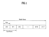
- FIG. 1 illustrates the structure of a radio frame.
- the radio frame includes 10 subframes, and one subframe includes two slots in the time domain.
- a time required to transmit one subframe is defined as a Transmission Time Interval (TTI).
- TTI Transmission Time Interval
- one subframe may have a length of 1 ms and one slot may have a length of 0.5 ms.
- One slot may include a plurality of OFDM symbols or Single Carrier Frequency Division Multiple Access (SC-FDMA) symbols in the time domain. Since an LTE system uses OFDMA in downlink (DL) and SC-FDMA in uplink (UL), the OFDM or SC-FDMA symbol indicates one symbol duration.
- a Resource Block (RB) is a resource allocation unit and includes a plurality of contiguous subcarriers in one slot.
- the structure of the radio frame is only exemplary. The number of subframes included in a radio frame, the number of slots included in a subframe, or the number of symbols included in a slot may be changed in various manners.
- FIG. 2 illustrates a resource grid of a DL slot.
- the DL slot includes a plurality of OFDM symbols in the time domain.
- One DL slot includes 7 (or 6) OFDM symbols and an RB may include 12 subcarriers in the frequency domain.
- Each element on the resource grid is referred to as a Resource Element (RE).
- One RB includes 12 ⁇ 7 (or 6) REs.
- the number of RBs, N RB included in the DL slot depends on a DL transmission band.
- the structure of a UL slot is the same as the structure of the DL slot except that OFDM symbols are replaced with SC-FDMA symbols.
- FIG. 3 illustrates the structure of a DL subframe.
- a maximum of 3 (or 4) OFDM symbols at the front part of a first slot of a subframe corresponds to a control region to which control channels are allocated.
- the remaining OFDM symbols correspond to a data region to which a Physical Downlink Shared Channel (PDSCH) is allocated.
- Examples of DL control channels used in the LTE system include, for example, a Physical Control Format Indicator Channel (PCFICH), a Physical Downlink Control Channel (PDCCH), a Physical Hybrid automatic repeat request Indicator Channel (PHICH), etc.
- the PCFICH is transmitted in the first OFDM symbol of a subframe and carries information about the number of OFDM symbols used for transmission of control channels in the subframe.
- the PHICH carries a Hybrid Automatic Repeat request (HARQ) Acknowledgment/Negative-Acknowledgment (ACK/NACK) signal as a response to UL transmission.
- HARQ Hybrid Automatic Repeat request
- ACK/NACK Hybrid Automatic Repeat request
- the DCI includes resource allocation information for a User Equipment (UE) or a UE group and other control information.
- UE User Equipment
- the DCI includes UL/DL scheduling information, a UL transmit (Tx) power control command, etc.
- the PDCCH carries a transmission format and resource allocation information for a Downlink Shared Channel (DL-SCH), a transmission format and resource allocation information for an Uplink Shared Channel (UL-SCH), paging information on a Paging Channel (PCH), system information on the DL-SCH, resource allocation information of a higher-layer control message such as a random access response transmitted on the PDSCH, a Tx power control command set for individual UEs in a UE group, a Tx power control command, activation indication information of Voice over IP (VoIP), and the like.
- a plurality of PDCCHs may be transmitted in the control region.
- a UE may monitor a plurality of PDCCHs.
- the PDCCH is transmitted on an aggregate of one or plural contiguous Control Channel Elements (CCEs).
- CCE is a logical allocation unit used to provide the PDCCH with a coding rate based on a radio channel state.
- the CCE corresponds to a plurality of Resource Element Groups (REGs).
- a format of the PDCCH and the number of bits of the PDCCH are determined according to the number of CCEs.
- a Base Station determines a PDCCH format according to DCI to be transmitted to a UE and attaches a Cyclic Redundancy Check (CRC) to control information.
- An identifier e.g.
- Radio Network Temporary Identifier (RNTI)) is masked to the CRC according to the owner or purposes of the PDCCH. For example, if the PDCCH is dedicated to a specific UE, an identifier of the UE (e.g. cell-RNTI (C-RNTI)) may be masked to the CRC. If the PDCCH is dedicated to a paging message, a paging identifier (e.g. paging-RNTI (P-RNTI)) may be masked to the CRC. If the PDCCH is for system information (more specifically, a System Information Block (SIB)), a System Information RNTI (SI-RNTI) may be masked to the CRC. If the PDCCH is for a random access response, a Random Access RNTI (RA-RNTI) may be masked to the CRC.
- SIB System Information Block
- SI-RNTI System Information RNTI
- RA-RNTI Random Access RNTI
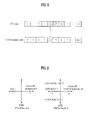
- FIG. 4 illustrates the structure of a UL subframe used in an LTE system.
- a UL subframe includes plural (e.g. two) slots. Each slot may include a different number of SC-FDMA symbols according to the length of a Cyclic Prefix (CP).
- the UL subframe is divided into a data region and a control region in the frequency domain.
- the data region includes a PUSCH and is used to transmit data signals such as voice signals.
- the control region includes a PUCCH and is used to transmit Uplink Control Information (UCI).
- UCI Uplink Control Information
- the PUCCH includes an RB pair located at both ends of the data region in the frequency domain and is hopped using the slot as a boundary.
- the PUCCH may be used to transmit the following control information.
- the amount of UCI that can be transmitted in a subframe by a UE is dependent upon the number of SC-FDMA symbols available for UCI transmission.
- the SC-FDMA symbols available for UCI transmission indicate the remaining SC-FDMA symbols other than SC-FDMA symbols that are used for reference signal transmission in a subframe.
- SRS Sounding Reference Signal
- the reference signal is used for coherent detection of a PUCCH.
- the PUCCH supports 7 formats according to transmission information.
- Table 1 shows the mapping relationship between PUCCH and UCI for use in LTE.
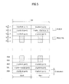
- FIG. 5 illustrates physical mapping of PUCCH formats to PUCCH regions.
- the number of PUCCH RBs available for use by PUCCH format 2/2a/2b (CQI), N RB 2 is transmitted to the UEs in the cell through broadcast signaling.
- FIG. 6 illustrates a slot level structure of PUCCH format 2/2a/2b.
- the PUCCH format 2/2a/2b is used for Channel State Information (CSI) transmission.
- the CSI includes CQI, PMI, RI, PTI, etc.
- SC-FDMA symbols #1 and #5 are used for Demodulation Reference Signal (DM RS) transmission in a slot in the case of normal CP. In the case of extended CP, only SC-FDMA symbol #3 is used for DM RS transmission in the slot.
- DM RS Demodulation Reference Signal
- 10 CSI bits are channel coded with a rate 1/2 punctured (20, k) Reed-Muller code in a subframe level to give 20 coded bits (not shown), which are then scrambled (not shown) and undergo Quadrature Phase Shift Keying (QPSK) constellation mapping (QPSK modulation).
- the coded bits may be scrambled in a similar way to PUSCH data with a length-31 Gold sequence. 10 QPSK modulated symbols are generated and 5 QPSK modulated symbols d0 to d4 are transmitted in each slot through corresponding SC-FDMA symbols.
- N UEs can be multiplexed on the same CSI PUCCH RB.
- the DM RS sequence is similar to a CSI sequence in the frequency domain but is not modulated by a CSI modulation symbol.
- Parameters/resources for periodic CSI reporting are semi-statically configured by higher layer signaling. For example, if PUCCH resource index n PUCCH 2 is set for CSI transmission, the CSI is periodically transmitted on the CSI PUCCH linked to the PUCCH resource index n PUCCH 2 .
- the PUCCH resource index n PUCCH 2 indicates a PUCCH RB and a CS ⁇ cs .
- FIG. 7 illustrates a slot level structure of PUCCH format 1a/1b.
- the PUCCH format 1a/1b is used for ACK/NACK transmission.
- SC-FDMA symbols #2/#3/#4 are used for DM RS transmission in the case of normal CP.
- SC-FDMA symbols #2/#3 are used for DM RS transmission. Accordingly, four SC-FDMA symbols are used for ACK/NACK transmission in one slot.
- ACK/NACK information and 2-bit ACK/NACK information are modulated using BPSK and QPSK modulation schemes, respectively, resulting in a single ACK/NACK modulation symbol do.
- ACK/NACK information is given as 1 for a positive ACK and as 0 for a negative ACK (NACK).
- Table 2 shows a modulation table defined for PUCCH formats 1a and 1b in legacy LTE. [Table 2] PUCCH format b (0),..., b ( M bit -1) d (0) 1a 0 1 1 1 -1 1b 00 1 01 - j 10 j 11 -1
- the PUCCH format 1a/1b perform time domain spreading using orthogonal spreading codes (e.g. Walsh-Hadamard or DFT codes) w0, w1, w2, and w3. Since code multiplexing is used in both the frequency and time domains in the case of PUCCH format 1a/1b, a large number of UEs can be multiplexed on the same PUCCH RB.
- orthogonal spreading codes e.g. Walsh-Hadamard or DFT codes
- RSs transmitted from different UEs are multiplexed in the same way as UCI.
- the number of CSs supported in an SC-FDMA symbol for PUCCH ACK/NACK RBs may be configured by a cell-specific higher-layer signaling parameter ⁇ shift PUCCH .
- ⁇ shift PUCCH ⁇ 1 2 3 indicates 12, 6, and 4 shifts, respectively.
- the number of spreading codes for ACK/NACK is limited by the number of RS symbols, because the multiplexing capacity of RS symbols is smaller than that of UCI symbols due to a smaller number of RS symbols.
- FIG. 8 illustrates determination of PUCCH resources for ACK/NACK.
- a PUCCH resource for ACK/NACK is not pre-allocated to each UE and a plurality of UEs separately uses a plurality of PUCCH resources at each time point.
- a PUCCH resource used by a UE to transmit ACK/NACK corresponds to a PUCCH on which scheduling information for corresponding DL data is carried.
- An entire region in which a PDCCH is transmitted in each DL subframe includes a plurality of CCEs and a PDCCH transmitted to the UE is comprised of one or more CCEs.
- the UE transmits ACK/NACK through a PUCCH resource corresponding to a specific CCE (e.g. first CCE) among CCEs constituting a PDCCH received thereby.
- a specific CCE e.g. first CCE
- each rectangle indicates a CCE and, in a UL CC, each rectangle indicates a PUCCH resource.
- Each PUCCH index corresponds to a PUCCH resource for ACK/NACK.
- the UE transmits ACK/NACK through a PUCCH of index 4 corresponding to the CCE of index 4 which is the first CCE of the CCEs constituting the PDCCH.
- N may equal to M, it is possible to design different M and N values and to overlap mapping of CCEs and PUCCHs.
- a PUCCH resource index in the LTE system is determined as follows.
- n 1 PUCCH n CCE + n 1 PUCCH
- n (1) PUCCH denotes a resource index of PUCCH format 1 for transmitting ACK/NACK/Discontinuous Transmission (DTX)
- N (1) PUCCH denotes a signaling value transmitted from a higher layer
- n CCE denotes the smallest value among CCE indexes used for PDCCH transmission.
- a CS, an orthogonal spreading code, and a Physical Resource Block (PRB), for PUCCH format 1a/1b are obtained from n (1) PUCCH .
- PRB Physical Resource Block
- the UE When the LTE system operates in TDD mode, the UE transmits one multiplexed ACK/NACK signal with respect to a plurality of PDSCHs received through different subframes. In more detail, the UE transmits one multiplexed ACK/NACK signal with respect to a plurality of PDSCHs using an ACK/NACK selection scheme.
- the ACK/NACK selection scheme is also called a PUCCH selection scheme.
- the UE occupies a plurality of UL physical channels in order to transmit the multiplexed ACK/NACK signal upon receiving multiple DL data.
- the UE may occupy the same number of PUCCHs using a specific CCE of PDCCHs indicating the respective PDSCHs.
- the multiplied ACK/NACK signal may be transmitted according to which PUCCH is selected from among the occupied plural PUCCHs and using a combination of modulation applied to the selected PUCCH and coded content.
- Table 3 shows the ACK/NACK selection scheme defined in the LTE system.
- HARQ-ACK(0), HARQ-ACK(1), HARQ-ACK(2), HARQ-ACK(3) Subframe n PUCCH,X b(0),b(1) ACK, ACK, ACK, ACK n (1) PUCCH,1 1,1 ACK, ACK, ACK, NACK/DTX n (1) PUCCH,1 1,0 NACK/DTX,NACK/DTX,NACK,DTX n (1) PUCCH,2 1,1 ACK, ACK, NACK/DTX, ACK n (1) PUCCH,1 1,0 NACK,DTX,DTX,DTX n (1) PUCCH,0 1,0 ACK, ACK, NACK/DTX, NACK/DTX n (1) PUCCH,1 1,0 ACK, NACK/DTX, NACK/DTX n (1) PUCCH,1 1,0 ACK, NACK/DTX, ACK, ACK n (1) PUCCH,3 0,1
- HARQ-ACK(i) indicates the HARQ ACK/NACK/DTX for the i-th data unit (where 0 ⁇ i ⁇ 3).
- DTX means there is no data unit transmitted for corresponding HARQ-ACK(i) or the UE does not detect the existence of the data unit corresponding to HARQ-ACK(i).
- a maximum of 4 PUCCH resources i.e. n (1) PUCCH,0 ⁇ n (1) PUCCH,3
- a multiplexed ACK/NACK is transmitted through one PUCCH resource selected from the occupied PUCCH resources.
- n (1) PUCCH,X indicates a PUCCH resource used for actual ACK/NACK transmission.
- b(0)b(1) indicates two bits transmitted through the selected PUCCH resource and is modulated using a QPSK scheme. For example, if the UE successfully decodes 4 data units, the UE transmits (1,1) through a PUCCH resource associated with n (1) PUCCH,1 .
- NACK and DTX are coupled as NACK/DTX (N/D) except for some cases because combinations of PUCCH resources and QPSK symbols are insufficient to indicate all possible ACK/NACK hypotheses.
- FIG. 9 illustrates multiplexing of ACK/NACK and SR by a UE.
- SR PUCCH format 1 The structure of SR PUCCH format 1 is the same as that of ACK/NACK PUCCH format 1a/1b shown in FIG. 9 .
- a PUCCH resource index m PUCCH , SRI 1 to be used by the UE for SR transmission is configured by UE-specific higher-layer signaling.
- FIG. 9 illustrates constellation mapping for simultaneous transmission of ACK/NACK and SR. Specifically, FIG. 9 illustrates modulation mapping of NACK (or (NACK, NACK) in the case of two MIMO codewords) to +1. When DTX is generated, it is processed as NACK.
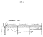
- FIG. 10 illustrates a Carrier Aggregation (CA) communication system.
- An LTE-A system uses carrier aggregation or bandwidth aggregation that uses a wider UL/DL bandwidth by aggregating a plurality of UL/DL frequency blocks for a wider frequency band.
- Each frequency block is transmitted using a CC.
- the CC may be understood as a carrier frequency (or center carrier, center frequency) for the corresponding frequency block.
- a wider UL/DL bandwidth can be supported by aggregating a plurality of UL/DL CCs.
- CCs may be contiguous or noncontiguous in the frequency domain.
- the bandwidths of the CCs may be independently determined.
- Asymmetric carrier aggregation in which the number of UL CCs differs from the number of DL CCs may be used. In the case of two DL CCs and one UL CC, for example, they may be configured such that the ratio of DL CCs to UL CCs is 2:1.
- the DL CC/UL CC link may be statically or semi-statically configured in a system.
- a frequency band that a specific UE can monitor/receive may be limited to M ( ⁇ N) CCs.
- Various parameters regarding carrier aggregation may be configured cell-specifically, UE group-specifically, or UE-specifically.
- control information may be configured so as to be transmitted and received only through a specific CC.
- This specific CC may be designated as a Primary CC (PCC) (or anchor CC) and the other CCs may be designated as Secondary CCs (SCCs).
- PCC Primary CC
- SCCs Secondary CCs
- LTE-A uses the concept of cells to manage radio resources.
- the cell is defined as a combination of DL and UL resources.
- the UL resource is not an essential component. Accordingly, the cell can be configured with the DL resource alone, or with both the DL resource and UL resource.
- linkage between a DL resource carrier frequency (or DL CC) and a UL resource carrier frequency (or UL CC) may be indicated by system information.
- a cell that operates on the primary frequency (or PCC) may be designated as a primary cell (Pcell) and a cell that operates on the secondary frequency (or SCC) may be designated as a secondary cell (SCell).
- PCC primary frequency
- SCell secondary cell
- the PCell is used for the UE to perform an initial connection establishment or connection re-establishment procedure.
- PCell may represent a cell designated during a handover process.
- the SCell is configurable after RRC connection establishment and may be used to provide additional radio resources.
- the PCell and SCell may be commonly designated as a serving cell. Accordingly, for a UE that is in an RRC_CONNECTED state without carrier aggregation or does not support carrier aggregation, only one serving cell configured with only the PCell is present. Meanwhile, for a UE in an RRC_CONNECTED state, for which carrier aggregation is configured, one or more serving cells including the PCell and SCell are present.
- a network may configure one or more SCells for a UE that supports carrier aggregation in addition to the PCell initially configured in the connection establishment procedure after an initial security activation procedure is initiated.
- a PDCCH for DL allocation may be transmitted through DL CC#0 and a corresponding PDSCH may be transmitted through DL CC#2.
- introduction of a Carrier Indicator Field may be considered. Presence or absence of the CIF within the PDCCH may be configured semi-statically and UE-specifically (or UE group-specifically) through higher-layer signaling (e.g., RRC signaling).
- RRC signaling e.g., RRC signaling
- a BS may allocate a DL CC set for monitoring a PDCCH in order to lower blind decoding complexity of a UE.
- the PDCCH monitoring DL CC set may be a part of all aggregated DL CCs and include one or more DL CCs.
- the UE can detect/decode the PDCCH only in the corresponding DL CC set. That is, if the BS schedules the PDSCH/PUSCH to the UE, the BS can transmit the PDCCH only through the PDCCH monitoring DL CC.
- the PDCCH monitoring DL CC set may be configured UE-specifically, UE group-specifically, or cell-specifically.
- the term "PDCCH monitoring DL CC" may be replaced with equivalent terms such as monitoring carrier or monitoring cell.
- CC aggregated for the UE may be replaced with equivalent terms such as serving CC, serving carrier, or serving cell.
- FIG. 11 illustrates scheduling in the case where multiple carriers are aggregated. It is assumed that three DL CCs are aggregated and a DL CC A is configured as a PDCCH monitoring DL CC.
- DL CCs A, B, and C may be referred to as serving CCs, serving carriers, or serving cells. If a CIF is disabled, the DL CCs may transmit only PDCCHs for scheduling PDSCHs thereof without the CIF according to an LTE PDCCH rule.
- the DL CC A (monitoring DL CC) may also transmit PDCCHs for scheduling PDSCHs of other CCs as well as a PDCCH for scheduling a PDSCH of the DL CC A, using the CIF.
- no PDCCH is transmitted in the DL CC B and DL CC C that are not configured as the PDCCH monitoring DL CC.
- ACK/NACK transmission using PUCCH format 1a/1b in legacy LTE it is considered to joint-code multiple ACK/NACK information (e.g. using a Reed-Muller code, Tail-biting convolutional code, etc.) and then to transmit multiple ACK/NACK information/signals using PUCCH format 2 or new PUCCH format (referred to as Enhanced PUCCH (E-PUCCH)).
- the E-PUCCH format includes a block-spreading based PUCCH format.
- ACK/NACK transmission using PUCCH format 2/E-PUCCH format after joint coding is exemplary and PUCCH format 2/E-PUCCH format may be used without restrictions on UCI transmission.
- PUCCH format 2/E-PUCCH format may be used to transmit ACK/NACK, CSI (e.g. CQI, PMI, RI, PTI, etc.), SR, or two or more pieces of information thereof together. Accordingly, in this specification, PUCCH format 2/E-PUCCH format may be used to transmit a joint coded UCI codeword irrespective of the type/number/size of UCI.
- FIG. 12 illustrates a block-spreading based E-PUCCH format in a slot level.
- PUCCH format 2 of legacy LTE one symbol sequence (d0 ⁇ d4 in FIG. 6 ) is transmitted over the time domain and UE multiplexing is performed using CSs ( ⁇ cs,x , where x is 0 to 4) of Constant-Amplitude Zero Auto-Correlation (CAZAC) sequence (r u,o ), as shown in FIG. 6 .
- CAZAC Constant-Amplitude Zero Auto-Correlation
- r u,o Constant-Amplitude Zero Auto-Correlation
- a block-spreading based E-PUCCH format one symbol sequence is transmitted over the frequency domain and UE multiplexing is performed using Orthogonal Cover Code (OCC) based time-domain spreading. That is, the symbol sequence is spread in the time domain by the OCC and then transmitted. Control signals of multiple UEs can be multiplexed using the OCC.
- the symbol sequence ⁇ d1,d2,... ⁇ may mean a modulation symbol sequence or a codeword bit sequence. If the symbol sequence ⁇ d1,d2,... ⁇ means the bit sequence, the block diagram of FIG. 13 further includes a codeword modulation block.
- the RS symbols may be generated from a CAZAC sequence having a specific CS. Moreover, the RS may be transmitted in a form in which a specific OCC is applied to (or multiplied by) multiple RS symbols of the time domain.
- Block-spread UCI is transmitted to a network through a Fast Fourier Transform (FFT) process and an Inverse Fast Fourier Transform (IFFT) process on an SC-FDMA symbol basis.
- FFT Fast Fourier Transform
- IFFT Inverse Fast Fourier Transform
- the block-spreading scheme modulates control information (e.g. ACK/NACK etc.) using an SC-FDMA scheme unlike PUCCH format 1 or 2 series of legacy LTE.
- FIG. 13 illustrates a block-spreading based E-PUCCH format in a slot level.
- a symbol sequence ⁇ d '0 ⁇ d '11 ⁇ in slot 0 is mapped to subcarriers of one SC-FDMA symbol and mapped to 5 SC-FDMA symbols by block-spreading using OCCs C1 to C5.
- a symbol sequence ⁇ d '12 ⁇ d '23 ⁇ in slot 1 is mapped to subcarriers of one SC-FDMA symbol and is mapped to 5 SC-FDMA symbols by block-spreading using OCCs C1 to C5.
- the symbol sequence ⁇ d '0 ⁇ d '11 ⁇ or ⁇ d '12 ⁇ d '23 ⁇ in each slot shows a form in which FFT or FFT/IFFT is applied to the symbol sequence ⁇ d1,d2,... ⁇ of FIG. 13 .
- the symbol sequence ⁇ d '0 ⁇ d '11 ⁇ or ⁇ d '12 ⁇ d '23 ⁇ is a form in which FFT is applied to the symbol sequence ⁇ d1,d2,... ⁇ of FIG. 13
- IFFT is additionally applied to the symbol sequence ⁇ d '0 ⁇ d '11 ⁇ or ⁇ d '12 ⁇ d '23 ⁇ to generate SC-FDMA symbols.
- the entire symbol sequence ⁇ d '0 ⁇ d '23 ⁇ is generated by joint coding one or more pieces of UCI.
- the front half ⁇ d '0 ⁇ d '11 ⁇ of the entire symbol sequence is transmitted through slot 0 and the rear half ⁇ d '12 ⁇ d '23 ⁇ of the entire symbol sequence is transmitted through slot 1.
- an OCC may vary on a slot basis and UCI data may be scrambled on an SC-FDMA symbol basis.
- a transmission scheme of channel coding based UCI (e.g. multiple ACK/NACK signals) using PUCCH format 2 or E-PUCCH format is referred to as a "multi-bit UCI coding" transmission scheme, for convenience of description.
- a multi-bit UCI coding transmission scheme indicates a method for joint-coding ACK/NACK information for PDSCHs (or PDCCHs in the Semi-Persistent Scheduling (SPS) release) of multiple DL cells or DTX information (representing that the PDCCHs are not received/detected) and transmitting the coded ACK/NACK block.
- SPS Semi-Persistent Scheduling
- a UE operates in an SU-MIMO mode in a certain DL cell and receives two codewords. Then, a total of four feedback states of ACK/ACK, ACK/NACK, NACK/ACK, and NACK/NACK for a corresponding cell may be present or a maximum of 5 feedback states further including DTX may be present. If the UE receives a single codeword, a maximum of three states of ACK, NACK, and DTX may be present (if NACK and DTX are identically processed, a total of two states of ACK and NACK/DTX may be present).
- the UE aggregates a maximum of 5 DL cells and operates in an SU-MIMO mode in all cells, a maximum of 5 5 transmittable feedback states is present.
- the size of a necessary ACK/NACK payload is at least 12 bits. If DTX and NACK are identically processed, the number of feedback states is 4 5 and the size of a necessary ACK/NACK payload is at least 10 bits.
- an implicit ACK/NACK selection scheme which uses a PUCCH resource corresponding to a PUCCH for scheduling each PDSCH of a corresponding UE (i.e. a PUCCH resource linked with the smallest CCE index) is basically used in order to secure a PUCCH resource of each UE.
- the implicit scheme is applied using PUCCH resources in different RBs, performance degradation may occur.
- an "explicit ACK/NACK selection" scheme using a PUCCH resource reserved for each UE (desirably, multiple PUCCH resources in the same RB or adjacent RBs) through RRC signaling etc. is additionally considered.
- ACK/NACK transmission through a single UE-specific UL cell (e.g. PCell) is considered.
- Table 4 shows an example of explicitly indicating PUCCH resources for HARQ ACK.
- HARQ-ACK resource value for PUCCH (ARI) n PUCCH 00 1st PUCCH resource value configured by higher layer 01 2nd PUCCH resource value configured by higher layer 10 3rd PUCCH resource value configured by higher layer 11 4th PUCCH resource value configured by higher layer
- ARI indicates an ACK/NACK resource indicator.
- a higher layer includes an RRC layer and an ARI value may be indicated through a PDCCH which carries a DL grant.
- the ARI value may be indicated through a Transmit Power Control (TPC) field of an Scell.
- TPC Transmit Power Control
- ACK/NACK or ACK/NACK state for a specific cell or "ACK/NACK or ACK/NACK state of a specific cell” means ACK/NACK or ACK/NACK state for a PDSCH (or SPS release PDCCH) scheduled in a corresponding cell.
- ACK/NACK or ACK/NACK state includes ACK, NACK, DTX, or NACK/DTX.
- DL PCell only one DL cell linked with a UL cell for ACK/NACK transmission (i.e. DL PCell) among a plurality of DL cells may be scheduled.
- a PUCCH resource i.e. LTE PUCCH format 1a/1b
- LTE PUCCH format 1a/1b which is implicitly designated (i.e. linked with the smallest CCE index through which a PDCCH is transmitted)
- a situation in which multi-bit ACK/NACK coding and explicit ACK/NACK selection should be applied only to ACK/NACK of a DL PCell by unnecessarily using an explicit resource may occur.
- a PCell fallback method may be considered.
- the PCell fallback method when one or multiple cells including a PCell are scheduled, if the other cells except for the PCell are all DTX (i.e. if only a PCell PDCCH (this means a PDCCH for scheduling a PDSCH transmitted through the PCell and may include an SPS release PDCCH) is detected or only a PCell SPS PDSCH (this means a PDSCH scheduled by an SPS scheme transmitted through the PCell) is received) (or NACK), ACK/NACK information may be transmitted using an implicit LTE PUCCH resource (e.g.
- the implicit LTE PUCCH resource may be replaced with an LTE PUCCH format 1a/1b resource reserved for ACK/NACK feedback for an SPS PDSCH).
- an explicit-PUCCH SR scheme may be considered in which an additional explicit LTE-A PUCCH (e.g. E-PUCCH) resource is reserved for SR transmission, and ACK/NACK information is transmitted through an ACK/NACK LTE-A PUCCH resource in the case of a negative SR and through an SR LTE-A PUCCH resource in the case of a positive SR, in a similar way in legacy LTE.
- E-PUCCH additional explicit LTE-A PUCCH
- the SR LTE-A PUCCH resource corresponding to the ACK/NACK LTE-A PUCCH resource is additionally used at least in an SR subframe.
- the SR subframe may be defined as a subframe in which SR information is transmitted or a subframe in which transmission of SR information is permitted, according to an implementation example.
- the SR subframe may be specified by higher-layer signaling (e.g. cycle or offset).
- the ACK/NACK LTE-A PUCCH resource and the SR LTE-A PUCCH resource may be divided into different UCI data parts and/or different RS parts.
- the different UCI data parts refer to UCI data parts using at least one of different PRBs, different scrambling codes, and different OCCs.
- the different RS parts refer to UCI data parts using at least one of different PRBs, different CSs, and different OCCs.
- a joint-coded SR scheme may be considered in which ACK/NACK information and SR information (e.g. 1-bit indicating a negative/positive SR, i.e. 0 for a negative SR and 1 for a positive SR) are joint-coded using an explicit LTE-A PUCCH resource for ACK/NACK transmission in an SR subframe and then transmitted.
- SR information e.g. 1-bit indicating a negative/positive SR, i.e. 0 for a negative SR and 1 for a positive SR
- an explicit LTE PUCCH resource e.g. LTE PUCCH format 1 resource
- an implicit LTE PUCCH resource i.e. PUCCH format 1a/1b resource
- LTE-A PUCCH resource reservation for an explicit-PUCCH SR, ACK/NACK payload extension for a joint-coded SR, and LTE PUCCH resource reservation for SR during PCell fallback are needed. Namely, resources may be wasted because the LTE PUCCH resource as well as the E-PUCCH resource for an SR in the SR subframe should be reserved.
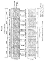
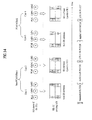
- FIG. 14 illustrates SR transmission according to a conventional explicit-PUCCH SR scheme.
- 3 DL Cells are shown.
- Cell#1 and Cell#2 indicate SCells, 'A' indicates ACK, 'N' indicates NACK, and 'D' indicates DTX.
- Case 1 and Case 2 indicate non-PCell fallback states because ACK/NACK (A/N) states of the SCells are not all NACK or DTX.
- Case 3 and Case 4 indicate PCell fallback states because ACK/NACK states of the SCells are all NACK or DTX.
- the operation of a UE for each case is as follows.
- Case 1 the UE transmits ACK/NACK information for a plurality of cells using a non-PCell fallback scheme in a non-SR subframe.
- the UE transmits a plurality of joint-coded ACK/NACK information using an explicitly indicated ACK/NACK LTE-A PUCCH (e.g. E-PUCCH) resource (e.g. resource of No. 1).
- the explicit resource for ACK/NACK transmission may be indicated using the ARI value shown in Table 4 and, in FIG. 14 , the ARI may be provided using a TPC field in PDCCH DCI of Cell#1 and/or Cell#2.
- the same ARI value is provided in a plurality of SCells.
- a TPC field of a PCell PDCCH is used to control the transmit power of a PUCCH for ACK/NACK transmission according to original use purpose thereof.
- Case 2 the UE transmits ACK/NACK information for a plurality of cells using a non-PCell fallback scheme in an SR subframe.
- ACK/NACK information is transmitted through an explicit ACK/NACK LTE-A PUCCH (e.g. E-PUCCH) resource (e.g. resource of No. 1) in the case of a negative SR and through an SR LTE-A PUCCH resource (e.g. resource of No. 2) in the case of a positive SR.
- E-PUCCH explicit ACK/NACK LTE-A PUCCH
- SR LTE-A PUCCH resource e.g. resource of No. 2
- the ACK/NACK information is transmitted through the explicitly indicated SR LTE-A PUCCH resource (e.g. resource of No. 2).
- the SR LTE-A PUCCH resource may be semi-statically reserved through higher-layer signaling (e.g. RRC signaling).
- RRC signaling e.g. RRC signaling
- the ACK/NACK information and a one-bit value indicating the negative/positive SR may be joint-coded together and then transmitted using the explicit ACK/NACK LTE-A PUCCH resource. Accordingly, in the joint-coded SR scheme, an ACK/NACK payload is extended by one bit for SR bit transmission.
- Case 3 the UE transmits ACK/NACK information for a PDSCH (or SPS release PDCCH of a PCell) corresponding to a PCell PDCCH using a PCell fallback scheme in the non-SR subframe.
- ACK/NACK information is transmitted using an implicit LTE PUCCH resource (e.g. LTE PUCCH format 1a/1b resource) (e.g. resource of No. 3) linked with the PCell PDCCH.
- the implicit LTE PUCCH resource is linked with the smallest CCE index for the PCell PDCCH (e.g. refer to Equation 1).
- Case 4 the UE transmits ACK/NACK information for a PDSCH (or SPS release PDCCH of a PCell) corresponding to a PCell PDCCH using the PCell fallback scheme in the SR subframe.
- ACK/NACK information is transmitted through an ACK/NACK LTE PUCCH resource (e.g. resource of No. 3) in the case of a negative SR and through an SR LTE PUCCH resource (e.g. resource of No. 4) in the case of a positive SR.
- the ACK/NACK information is transmitted through the explicitly indicated SR LTE PUCCH resource (e.g. resource of No. 4).
- the SR LTE PUCCH resource may be semi-statically reserved through higher-layer signaling (e.g. RRC signaling).
- the present invention proposes that PCell fallback be permitted only in the non-SR subframe in order to reduce overhead caused by SR transmission during transmission of multiple ACK/NACK signals for multiple cells. That is, PCell fallback is not applied in the SR subframe.
- transmission of multiple ACK/NACK signals may be performed using multi-bit ACK/NACK coding and (explicit) ACK/NACK selection schemes, the present invention is not limited thereto.
- ACK/NACK and/or SR transmission can be performed only using the multi-bit ACK/NACK coding and explicit ACK/NACK selection schemes/resources irrespective of presence/absence of PCell scheduling and ACK/NACK information per cell.
- FIG. 15 illustrates SR transmission using an explicit-PUCCH SR scheme according to an embodiment of the present invention.
- 3 DL Cells are shown.
- Cell#1 and Cell#2 indicate SCells, and 'A', 'N', and 'D' indicate ACK, NACK, and DTX, respectively.
- Cases 1 and 2 are the same as Cases 1 and 3 of FIG. 14 described above.
- Cases 3 and 4 satisfy a PCell fallback condition because the ACK/NACK states of Scells are all NACK or DTX.
- an ACK/NACK transmission event has occurred in an SR subframe
- application of a PCell fallback scheme is limited according to the present invention.
- the present method shows the case in which application of the PCell fallback scheme is unconditionally limited when the ACK/NACK transmission event occurs in the SR subframe.
- ACK/NACK information is transmitted using an ACK/NACK LTE-A PUCCH (e.g. E-PUCCH) resource (e.g. resource of No.
- the ACK/NACK information and a one-bit value indicating the negative/positive SR may be joint-coded together and then transmitted using the explicit ACK/NACK LTE-A PUCCH resource (e.g. resource of No. 1).
- an explicit resource for ACK/NACK transmission may be indicated using the ARI value shown in Table 4 and, in FIG. 15 , the ARI may be given using a TPC field in PDCCH DCI of Cell#1 and/or Cell#2.
- a TPC field of a PCell PDCCH may be used to control the transmit power of a PUCCH for ACK/NACK transmission according to original use purpose thereof.
- the following problems may occur. For example, if only a PCell PDCCH (and a PDSCH corresponding thereto) is detected in a DL subframe k-n (e.g.
- the UE transmits ACK/NACK information corresponding to the PCell PDCCH in a UL subframe k.
- the UE should transmit ACK/NACK information using an explicitly indicated LTE-A PUCCH resource according to the present method.
- the LTE-A PUCCH resource is signaled using a TPC field of an SCell PDCCH as described above, the UE cannot be aware of an explicit LTE-A PUCCH resource through which ACK/NACK information should be transmitted.
- an explicit ACK/NACK LTE-A PUCCH resource it is necessary to semi-statically pre-configure/pre-fix an explicit ACK/NACK LTE-A PUCCH resource to be used in the SR subframe.
- the explicit ACK/NACK LTE-A PUCCH resource is previously fixed in the SR subframe, another problem may occur. For example, if an SCell PDCCH (and a PDCCH corresponding thereto) is detected in the DL subframe k-n, the UE transmits ACK/NACK information corresponding to the SCell PDCCH in the UL subframe k. At this time, the explicit LTE-A PUCCH resource for ACK/NACK transmission is indicated by the TPC field of the SCell PDCCH.
- the UL subframe k is the SR subframe
- two explicit ACK/NACK LTE-A PUCCH resources coexist. That is, the explicit ACK/NACK LTE-A PUCCH resource pre-configured/pre-fixed for the SR subframe and the explicit LTE-A PUCCH resource indicated by the TPC field of the SCell PDCCH coexist. Accordingly, there is a problem because UE does not know which resource of the two LTE-A PUCCH resources should be used to transmit ACK/NACK information.
- the UE transmit ACK/NACK using the explicit ACK/NACK LTE-A PUCCH resource pre-configured/pre-fixed for the SR subframe.
- the TPC of the SCell PDCCH transmitted in the DL subframe k-n may have a scheduling restriction so as that an ARI value indicates the above-described pre-configured/pre-fixed explicit ACK/NACK LTE-A PUCCH resource.
- the UE may assume that the ARI value of the SCell PDCCH is identical to the ARI value indicating the pre-configured/pre-fixed explicit ACK/NACK LTE-A PUCCH resource.
- the UE may perform the following operations.
- Option 1 the UE may disregard the ARI value of the SCell PDCCH.
- the UE may use the ARI value of the SCell PDCCH as CRC for PDCCH error check. Accordingly, if the ARI value of the SCell PDCCH is different from the ARI value indicating the pre-configured/pre-fixed explicit ACK/NACK LTE-A PUCCH resource, the UE judges that the SCell PDCCH has an error and may not perform decoding of a PDSCH indicated by the SCell PDCCH.
- the UE does not interpret a value of the TPC field of the SCell PDCCH (of the SR subframe) as an ARI and may use the value to control the transmit power of the PUCCH according to an original use purpose.
- the present invention additionally proposes that PCell fallback be permitted only in the case of a negative SR in the SR subframe (in addition to the non-SR subframe) in order to reduce SR transmission overhead, during transmission of multiple ACK/NACK signals for multiple cells. That is, PCell fallback is not applied in the case of a positive SR in the SR subframe.
- Transmission of multiple ACK/NACK signals is performed using, but not limited to, the multi-bit ACK/NACK coding and (explicit) ACK/NACK selection schemes.
- ACK/NACK and/or SR transmission can be performed only using the multi-bit ACK/NACK coding and explicit ACK/NACK selection schemes/resources irrespective of presence/absence of PCell scheduling and ACK/NACK information per cell.
- FIG. 16 illustrates SR transmission using an explicit-PUCCH SR scheme according to another embodiment of the present invention.
- 3 DL Cells are shown.
- 'A', 'N', and 'D' indicate ACK, NACK, and DTX, respectively.
- Cell#1 and Cell#2 indicate SCells. Cases 1 and 2 are the same as Cases 1 and 3 of FIG. 14 described above.
- Cases 3 and 4 satisfy a PCell fallback condition because the ACK/NACK states of SCells are all NACK or DTX.
- application of the PCell fallback scheme is conditionally limited according to the present invention. Specifically, in the case of a positive SR in the SR subframe, application of the PCell fallback scheme is limited. Accordingly, in the case of a negative SR, ACK/NACK information is transmitted using an implicit ACK/NACK LTE PUCCH (e.g. PUCCH format 1a/1b resource (e.g. resource of No. 3) according to the PCell fallback scheme.
- PUCCH e.g. PUCCH format 1a/1b resource (e.g. resource of No. 3
- the ACK/NACK information is transmitted using an SR LTE-A PUCCH resource (e.g. resource of No. 2) according to an explicit-PUCCH SR scheme (Case 4).
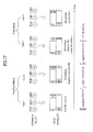
- FIG. 17 illustrates SR transmission according to a conventional joint-coded SR scheme.
- 3 DL Cells are shown.
- Cell#1 and Cell#2 indicate SCells and 'A' 'N', and 'D' indicates ACK, NACK, and DTX, respectively.
- Case 1 and Case 2 indicate non-PCell fallback states because ACK/NACK states of the SCells are not all NACK or DTX.
- Case 3 and Case 4 indicate PCell fallback states because ACK/NACK states of the SCells are all NACK or DTX.
- the operation of a UE for each case is as follows.
- Case 1 the UE transmits ACK/NACK information for a plurality of cells using a non-PCell fallback scheme in a non-SR subframe.
- the UE transmits a plurality of joint-coded ACK/NACK information using an explicitly indicated ACK/NACK LTE-A PUCCH (e.g. E-PUCCH) resource (e.g. resource of No. 1).
- the explicit resource for ACK/NACK transmission may be indicated using the ARI value shown in Table 4 and, in FIG. 17 , the ARI may be provided using a TPC field in PDCCH DCI of Cell#1 and/or Cell#2.
- the same ARI value is provided in a plurality of SCells.
- a TPC field of a PCell PDCCH is used to control the transmit power of a PUCCH for ACK/NACK transmission according to original use purpose thereof.
- Case 2 the UE transmits ACK/NACK information for a plurality of cells using a non-PCell fallback scheme in an SR subframe.
- ACK/NACK information and a one-bit value (SR indication information) indicating a negative/positive SR may be joint-coded together and then transmitted using the explicit ACK/NACK LTE-A PUCCH resource (e.g. resource of No. 1).
- the SR indication information may be set to 1 for the positive SR and may be set to 0 for the negative SR.
- the SR indication information may be added to the front/end of the ACK/NACK information and may be joint-coded with the ACK/NACK information.
- the ACK/NACK information and SR indication information are transmitted through the explicit ACK/NACK LTE-A PUCCH resource (e.g. resource of No. 1) irrespective of whether the SR subframe is a positive or negative SR. Therefore, an SR LTE-A PUCCH resource is not needed in the SR subframe.
- the explicit ACK/NACK LTE-A PUCCH resource e.g. resource of No. 1
- Case 3 the UE transmits ACK/NACK information for a PDSCH (or SPS release PDCCH of a PCell) corresponding to a PCell PDCCH using a PCell fallback scheme in an SR subframe (negative SR) or a non-SR subframe.
- ACK/NACK information is transmitted using an implicit LTE PUCCH resource (e.g. LTE PUCCH format 1a/1b resource) (e.g. resource of No. 2) linked with the PCell PDCCH.
- the implicit LTE PUCCH resource is linked with the smallest CCE index for the PCell PDCCH (e.g. refer to Equation 1).
- Case 4 the UE transmits ACK/NACK information for a PDSCH (or SPS release PDCCH of a PCell) corresponding to a PCell PDCCH using the PCell fallback scheme in the SR subframe (positive SR).
- ACK/NACK information is transmitted through an ACK/NACK LTE PUCCH resource (e.g. resource of No. 2) in the case of a negative SR and through an SR LTE PUCCH resource (e.g. resource of No. 3) in the case of a positive SR.
- the ACK/NACK information is transmitted through the explicitly indicated SR LTE PUCCH resource (e.g. resource of No. 3).
- the SR LTE PUCCH resource may be semi-statically reserved through higher-layer signaling (e.g. RRC signaling).
- FIG. 18 illustrates SR transmission using a joint-coded SR scheme according to an embodiment of the present invention.
- 3 DL Cells are shown.
- Cell#1 and Cell#2 indicate SCells and 'A', 'N', and 'D' indicate ACK, NACK, and DTX, respectively.
- Cases 1, 2, and 3 are the same as Cases 1, 3, and 2 of FIG. 17 described above.
- Case 4 satisfies a PCell fallback condition because the ACK/NACK states of SCells are all NACK or DTX.
- application of the PCell fallback scheme is limited according to the present invention.
- the present method shows the case in which application of the PCell fallback scheme is unconditionally limited when the ACK/NACK transmission event occurs in the SR subframe. Namely, in the SR subframe, ACK/NACK and SR are unconditionally joint-coded according to the joint-coded SR scheme irrespective of whether PCell fallback is applied and irrespective of a positive/negative SR and then are transmitted using a pre-configured ACK/NACK PUCCH resource.
- ACK/NACK information and a one-bit value (SR indication information) indicating the negative/positive SR may be joint-coded together and then transmitted using the explicit ACK/NACK LTE-A PUCCH resource (e.g. resource of No. 1) in the SR subframe. Therefore, as opposed to a conventional method, resources can be efficiently used because it is not necessary to reserve an LTE PUCCH resource for SR in the SR subframe in preparation for PCell fallback.
- FIG. 19 illustrates SR transmission using a joint-coded SR scheme according to another embodiment of the present invention.
- 3 DL Cells are shown.
- 'A', 'N', and 'D' indicate ACK, NACK, and DTX, respectively.
- Cell#1 and Cell#2 indicate SCells. Cases 1 and 3 are the same as Cases 1 and 2 of FIG. 17 described above.
- Cases 2 and 4 satisfy a PCell fallback condition because the ACK/NACK states of SCells are all NACK or DTX.
- application of the PCell fallback scheme is conditionally limited according to the present invention. Specifically, application of the PCell fallback scheme is limited in the case of a positive SR in the SR subframe.
- ACK/NACK and SR are unconditionally joint-coded irrespective of whether PCell fallback is applied and are transmitted using a pre-configured ACK/NACK PUCCH resource.
- ACK/NACK and SR are unconditionally joint-coded and transmitted using the pre-configured ACK/NACK PUCCH resource.
- ACK/NACK is transmitted using an implicitly indicated PUCCH resource.
- ACK/NACK information is transmitted using an implicit ACK/NACK LTE PUCCH (e.g. PUCCH format 1a/1b) resource (e.g. resource of No. 2) according to the PCell fallback scheme (Case 4).
- ACK/NACK information and one-bit SR indication information are joint-coded together and then are transmitted using the ACK/NACK LTE-A PUCCH resource (e.g. resource of No. 1) according to the joint-coded SR scheme (Case 2).
- the joint-coded SR scheme (Case 2).
- it is necessary to semi-statically pre-configure/pre-fix the explicit ACK/NACK LTE-A PUCCH resource to be used in the SR subframe e.g.
- the explicit ACK/NACK LTE-A PUCCH resource pre-indicated for the SR subframe and the explicit LTE-A PUCCH resource indicated by a TPC field of an SCell PDCCH may coexist.
- the UE transmit ACK/NACK using the explicit ACK/NACK LTE-A PUCCH resource pre-configured/pre-fixed for the SR subframe in a similar way to the above description.
- the TPC of the SCell PDCCH transmitted in the DL subframe k-n may have a scheduling restriction so as that an ARI value indicates the above-described pre-fixed explicit ACK/NACK LTE-A PUCCH resource.
- the UE may assume that the ARI value of the SCell PDCCH is identical to the ARI value indicating the pre-fixed explicit ACK/NACK LTE-A PUCCH resource.
- the UE may perform the following operations.
- Option 1 the UE may disregard the ARI value of the SCell PDCCH.
- the UE may use the ARI value of the SCell PDCCH as CRC for PDCCH error check. Accordingly, if the ARI value of the SCell PDCCH is different from the ARI value indicating the pre-fixed explicit ACK/NACK LTE-A PUCCH resource, the UE judges that the SCell PDCCH has an error and may not perform decoding of a PDSCH indicated by the SCell PDCCH.
- the UE does not interpret a value of the TPC field of the SCell PDCCH (of the SR subframe) as an ARI and may use the value to control the transmit power of the PUCCH according to an original use purpose.
- FIG. 20 illustrates a BS and a UE which are applicable to an embodiment of the present invention. If a wireless communication system includes a relay, communication over a backhaul link is performed between the BS and the relay and communication over an access link is performed between the relay and the UE. Accordingly, the BS and UE shown in FIG. 20 may be replaced with the relay according to circumstance.
- a wireless communication system includes a BS 110 and a UE 120.
- the BS 110 includes a processor 112, a memory 114, and a Radio Frequency (RF) unit 116.
- the processor 112 may be configured to implement the procedures and/or methods proposed in the present invention.
- the memory 114 is connected to the processor 112 and stores information related to operation of the processor 112.
- the RF unit 116 is connected to the processor 112 and transmits and/or receives radio signals.
- the UE 120 includes a processor 122, a memory 124, and an RF unit 126.
- the processor 122 may be configured to implement the procedures and/or methods proposed in the present invention.
- the memory 124 is connected to the processor 122 and stores information related to operation of the processor 122.
- the RF unit 126 is connected to the processor 122 and transmits and/or receives radio signals.
- the BS 110 and/or the UE 120 may have a single antenna or multiple antennas.
- a specific operation described as being performed by the BS may be performed by an upper node of the BS.
- various operations performed for communication with the UE may be performed by the BS, or network nodes other than the BS.
- the term BS may be replaced with the term fixed station, Node B, eNode B (eNB), access point, etc.
- UE may be replaced with the term Mobile Station (MS), Mobile Subscriber Station (MSS), etc.
- the embodiments of the present invention may be achieved by various means, for example, hardware, firmware, software, or a combination thereof.
- the exemplary embodiments of the present invention may be achieved by one or more Application Specific Integrated Circuits (ASICs), Digital Signal Processors (DSPs), Digital Signal Processing Devices (DSPDs), Programmable Logic Devices (PLDs), Field Programmable Gate Arrays (FPGAs), processors, controllers, microcontrollers, microprocessors, etc.
- ASICs Application Specific Integrated Circuits
- DSPs Digital Signal Processors
- DSPDs Digital Signal Processing Devices
- PLDs Programmable Logic Devices
- FPGAs Field Programmable Gate Arrays
- processors controllers, microcontrollers, microprocessors, etc.
- the exemplary embodiments of the present invention may be achieved by a module, a procedure, a function, etc. performing the above-described functions or operations.
- Software code may be stored in a memory unit and executed by a processor.
- the memory unit may be located at the interior or exterior of the processor and may transmit and receive data to and from the processor via various known means.
- the present invention may be used for a wireless communication device such as a UE, a relay, and a BS.
Landscapes
- Engineering & Computer Science (AREA)
- Signal Processing (AREA)
- Computer Networks & Wireless Communication (AREA)
- Quality & Reliability (AREA)
- Mobile Radio Communication Systems (AREA)
Applications Claiming Priority (2)
| Application Number | Priority Date | Filing Date | Title |
|---|---|---|---|
| US36785810P | 2010-07-26 | 2010-07-26 | |
| PCT/KR2011/005496 WO2012015216A2 (fr) | 2010-07-26 | 2011-07-26 | Procédé et dispositif de transmission d'informations de commande |
Publications (3)
| Publication Number | Publication Date |
|---|---|
| EP2600549A2 true EP2600549A2 (fr) | 2013-06-05 |
| EP2600549A4 EP2600549A4 (fr) | 2016-11-30 |
| EP2600549B1 EP2600549B1 (fr) | 2019-09-04 |
Family
ID=45530591
Family Applications (1)
| Application Number | Title | Priority Date | Filing Date |
|---|---|---|---|
| EP11812746.3A Active EP2600549B1 (fr) | 2010-07-26 | 2011-07-26 | Procédé et dispositif de transmission d'informations de commande |
Country Status (4)
| Country | Link |
|---|---|
| US (2) | US9084243B2 (fr) |
| EP (1) | EP2600549B1 (fr) |
| CN (1) | CN103026649B (fr) |
| WO (1) | WO2012015216A2 (fr) |
Cited By (3)
| Publication number | Priority date | Publication date | Assignee | Title |
|---|---|---|---|---|
| EP2835920A4 (fr) * | 2012-04-05 | 2016-04-27 | Lg Electronics Inc | Procédé et appareil d'agrégation de porteuses dans des systèmes de communication sans fil |
| EP2547058A4 (fr) * | 2010-03-10 | 2017-04-19 | LG Electronics Inc. | Procédé et appareil de transmission d'informations de commande de liaison montante dans système de communication sans fil |
| WO2019053165A1 (fr) * | 2017-09-15 | 2019-03-21 | Telefonaktiebolaget Lm Ericsson (Publ) | Techniques de modulation dépendant du taux de codage |
Families Citing this family (28)
| Publication number | Priority date | Publication date | Assignee | Title |
|---|---|---|---|---|
| US9042357B2 (en) * | 2010-07-26 | 2015-05-26 | Lg Electronics Inc. | Method and apparatus for transmitting uplink control information in a wireless communication system |
| WO2012015216A2 (fr) * | 2010-07-26 | 2012-02-02 | 엘지전자 주식회사 | Procédé et dispositif de transmission d'informations de commande |
| WO2012050342A2 (fr) * | 2010-10-12 | 2012-04-19 | 엘지전자 주식회사 | Procédé et dispositif pour transmettre des informations de commande dans un système de communication sans fil |
| US10051622B2 (en) * | 2011-03-11 | 2018-08-14 | Lg Electronics Inc. | Method for setting dynamic subframe in wireless communication system and device therefor |
| JP5927661B2 (ja) * | 2011-08-12 | 2016-06-01 | シャープ株式会社 | 端末装置、基地局装置、集積回路および通信方法 |
| CN105227266B (zh) * | 2012-01-12 | 2019-06-14 | 华为技术有限公司 | 传输上行控制信息的方法、用户设备和基站 |
| US20130195027A1 (en) * | 2012-01-30 | 2013-08-01 | Qualcomm Incorporated | Method and Apparatus for Channel Fallback in Enhanced Cell Forward Access Channel Dedicated Channel |
| EP3324562B1 (fr) * | 2012-02-29 | 2021-09-29 | Samsung Electronics Co., Ltd. | Procédé et appareil d'émission-réception de canal associé à un terminal supportant une transmission semi-duplex dans un système de communication mobile |
| CN103733709B (zh) | 2012-05-11 | 2018-08-07 | 太阳专利信托公司 | 终端装置和发送方法 |
| US9615379B2 (en) * | 2012-10-30 | 2017-04-04 | Telefonaktiebolaget Lm Ericson (Publ) | Scheduling request transmission method and apparatus for decoupled downlink-uplink |
| ES2764401T3 (es) * | 2013-08-01 | 2020-06-03 | Huawei Tech Co Ltd | Método y dispositivo para configurar recursos de transmisión de datos |
| JP6446743B2 (ja) * | 2013-08-05 | 2019-01-09 | シャープ株式会社 | 端末、基地局、および、通信方法 |
| EP3192204B8 (fr) * | 2014-09-10 | 2020-02-19 | Telefonaktiebolaget LM Ericsson (publ) | Noeud d'accès radio, terminal de communication, et procédés exécutés dans celui-ci |
| CN111447687B (zh) * | 2014-12-31 | 2024-04-12 | 华为技术有限公司 | 一种用户设备、接入网设备和反馈信息发送和接收方法 |
| US10455525B2 (en) * | 2015-01-28 | 2019-10-22 | Lg Electronics Inc. | Method for transmitting control information, and apparatus therefor |
| CN107534537B (zh) * | 2015-03-09 | 2020-03-13 | 康卡斯特有线通信有限责任公司 | 用于资源选择的调度请求 |
| EP3335508B1 (fr) * | 2015-08-13 | 2024-09-25 | Apple Inc. | Adaptation du seuil de détection d'énergie pour accès assisté sous licence d'un lte dans une bande sans licence |
| US10218474B2 (en) * | 2015-09-02 | 2019-02-26 | Htc Corporation | Device and method of handling scheduling request transmission |
| CN112910607A (zh) * | 2016-01-11 | 2021-06-04 | 中兴通讯股份有限公司 | 上行控制信息的发送方法及装置 |
| US10624125B2 (en) * | 2016-10-26 | 2020-04-14 | Qualcomm Incorporated | Techniques for semi-autonomously scheduling an uplink transmission in a shared radio frequency spectrum band |
| US10616916B2 (en) * | 2017-05-31 | 2020-04-07 | Kt Corporation | Methods for multiplexing scheduling request information and HARQ ACK/NACK information while transmitting and receiving PUCCH and apparatuses thereof |
| JP6968263B2 (ja) * | 2017-08-11 | 2021-11-17 | 中▲興▼通▲訊▼股▲ふぇん▼有限公司Zte Corporation | 無線通信におけるリソース配分のための方法および装置 |
| BR112020004360A2 (pt) * | 2017-09-08 | 2020-09-08 | Huawei Technologies Co., Ltd. | método de transmissão de sinal, aparelho relacionado, e sistema |
| US11356987B2 (en) * | 2017-09-30 | 2022-06-07 | Samsung Electronics Co., Ltd. | Method and equipment for transmitting uplink control information and setting uplink time advance |
| US11251880B2 (en) | 2018-07-19 | 2022-02-15 | Futurewei Technologies, Inc. | CA power measurement |
| CN111435847B (zh) * | 2019-01-11 | 2022-07-12 | 华为技术有限公司 | 传输信息的方法和装置 |
| CN112889230A (zh) * | 2019-09-30 | 2021-06-01 | Oppo广东移动通信有限公司 | 上行控制信息的传输方法及装置 |
| US20230276524A1 (en) * | 2022-02-25 | 2023-08-31 | Hong Kong Applied Science And Technology Research Institute Co., Ltd. | Method and Device for Detecting Partial Discontinuous Transmission (DTX) Using Bits Reconstruction |
Family Cites Families (13)
| Publication number | Priority date | Publication date | Assignee | Title |
|---|---|---|---|---|
| US7042858B1 (en) | 2002-03-22 | 2006-05-09 | Jianglei Ma | Soft handoff for OFDM |
| KR100956494B1 (ko) * | 2007-06-14 | 2010-05-07 | 엘지전자 주식회사 | 제어신호 전송 방법 |
| JP5038060B2 (ja) * | 2007-08-14 | 2012-10-03 | 株式会社エヌ・ティ・ティ・ドコモ | 移動通信システム、基地局装置、ユーザ装置及び方法 |
| US8848620B2 (en) | 2008-02-04 | 2014-09-30 | Qualcomm Incorporated | Simultaneous transmission of acknowledgement, channel quality indicator and scheduling request |
| US8121082B2 (en) * | 2008-02-05 | 2012-02-21 | Nokia Siemens Networks Oy | DTX detection when ACK/NACK is transmitted with scheduling request |
| US8345605B2 (en) * | 2008-02-21 | 2013-01-01 | Texas Instruments Incorporated | Transmission of bundled feedback in wireless networks |
| KR20100052646A (ko) * | 2008-11-11 | 2010-05-20 | 삼성전자주식회사 | 반송파 결합을 지원하는 셀룰러 무선통신시스템을 위한 하향링크 전송전력 분산 방법 및 장치 |
| KR20100058398A (ko) * | 2008-11-24 | 2010-06-03 | 엘지전자 주식회사 | 무선 통신 시스템에서 참조신호 전송 방법 |
| US8295253B2 (en) * | 2009-02-05 | 2012-10-23 | Qualcomm Incorporated | Efficient ACK transmission for uplink semi-persistent scheduling release in LTE |
| US20110205981A1 (en) * | 2009-08-13 | 2011-08-25 | Changsoo Koo | Multiplexing uplink l1/l2 control and data |
| RU2557164C2 (ru) * | 2009-10-01 | 2015-07-20 | Интердиджитал Пэйтент Холдингз, Инк. | Передача управляющих данных восходящей линии связи |
| CN201967138U (zh) * | 2009-11-19 | 2011-09-07 | 交互数字专利控股公司 | 无线发射/接收单元 |
| WO2012015216A2 (fr) * | 2010-07-26 | 2012-02-02 | 엘지전자 주식회사 | Procédé et dispositif de transmission d'informations de commande |
-
2011
- 2011-07-26 WO PCT/KR2011/005496 patent/WO2012015216A2/fr active Application Filing
- 2011-07-26 EP EP11812746.3A patent/EP2600549B1/fr active Active
- 2011-07-26 CN CN201180036347.6A patent/CN103026649B/zh active Active
- 2011-07-26 US US13/809,826 patent/US9084243B2/en active Active
-
2015
- 2015-06-19 US US14/745,022 patent/US9756620B2/en active Active
Cited By (10)
| Publication number | Priority date | Publication date | Assignee | Title |
|---|---|---|---|---|
| EP2547058A4 (fr) * | 2010-03-10 | 2017-04-19 | LG Electronics Inc. | Procédé et appareil de transmission d'informations de commande de liaison montante dans système de communication sans fil |
| EP2835920A4 (fr) * | 2012-04-05 | 2016-04-27 | Lg Electronics Inc | Procédé et appareil d'agrégation de porteuses dans des systèmes de communication sans fil |
| US9462586B2 (en) | 2012-04-05 | 2016-10-04 | Lg Electronics Inc. | Method and device for aggregating carriers in wireless communication system |
| US9462587B2 (en) | 2012-04-05 | 2016-10-04 | Lg Electronics Inc. | Method and apparatus for aggregating carriers in wireless communication systems |
| US9743409B2 (en) | 2012-04-05 | 2017-08-22 | Lg Electronics Inc. | Method and apparatus for aggregating carriers in wireless communication systems |
| US10039106B2 (en) | 2012-04-05 | 2018-07-31 | Lg Electronics Inc. | Method and apparatus for aggregating carriers in wireless communication systems |
| US10448402B2 (en) | 2012-04-05 | 2019-10-15 | Lg Electronics Inc. | Method and apparatus for aggregating carriers in wireless communication systems |
| US10887883B2 (en) | 2012-04-05 | 2021-01-05 | Lg Electronics Inc. | Method and apparatus for aggregating carriers in wireless communication systems |
| WO2019053165A1 (fr) * | 2017-09-15 | 2019-03-21 | Telefonaktiebolaget Lm Ericsson (Publ) | Techniques de modulation dépendant du taux de codage |
| US11817947B2 (en) | 2017-09-15 | 2023-11-14 | Telefonaktiebolaget Lm Ericsson (Publ) | Code-rate-dependent modulation techniques |
Also Published As
| Publication number | Publication date |
|---|---|
| CN103026649B (zh) | 2017-04-12 |
| EP2600549A4 (fr) | 2016-11-30 |
| WO2012015216A3 (fr) | 2012-04-19 |
| US9756620B2 (en) | 2017-09-05 |
| US9084243B2 (en) | 2015-07-14 |
| WO2012015216A2 (fr) | 2012-02-02 |
| CN103026649A (zh) | 2013-04-03 |
| US20130114556A1 (en) | 2013-05-09 |
| EP2600549B1 (fr) | 2019-09-04 |
| US20150289259A1 (en) | 2015-10-08 |
Similar Documents
| Publication | Publication Date | Title |
|---|---|---|
| US9756620B2 (en) | Method and device for transmitting control information | |
| US9800394B2 (en) | Method and apparatus for transmitting control information | |
| EP2600580B1 (fr) | Procédé et dispositif de transmission d'informations de commande | |
| US9736820B2 (en) | Method and device for transmitting control information | |
| EP3547586B1 (fr) | Procédé et appareil de transmission d'informations de commande | |
| US8976751B2 (en) | Method for transmitting control information and apparatus for same | |
| EP2453605B1 (fr) | Procédé de transmission d'informations de commande et dispositif correspondant | |
| US9078252B2 (en) | Method and apparatus for transmitting control information | |
| KR101979848B1 (ko) | 제어 정보를 전송하는 방법 및 이를 위한 장치 | |
| US9113457B2 (en) | Method and apparatus for transmitting control information | |
| EP3923497B1 (fr) | Procédé de transmission d'informations de commande et appareil correspondant | |
| US20130322391A1 (en) | Method and apparatus for transmitting uplink control information in a wireless communication system | |
| US20140056184A1 (en) | Method for transmitting control information and apparatus for same |
Legal Events
| Date | Code | Title | Description |
|---|---|---|---|
| PUAI | Public reference made under article 153(3) epc to a published international application that has entered the european phase |
Free format text: ORIGINAL CODE: 0009012 |
|
| 17P | Request for examination filed |
Effective date: 20130218 |
|
| AK | Designated contracting states |
Kind code of ref document: A2 Designated state(s): AL AT BE BG CH CY CZ DE DK EE ES FI FR GB GR HR HU IE IS IT LI LT LU LV MC MK MT NL NO PL PT RO RS SE SI SK SM TR |
|
| DAX | Request for extension of the european patent (deleted) | ||
| A4 | Supplementary search report drawn up and despatched |
Effective date: 20161028 |
|
| RIC1 | Information provided on ipc code assigned before grant |
Ipc: H04L 1/18 20060101ALI20161024BHEP Ipc: H04J 11/00 20060101AFI20161024BHEP Ipc: H04L 1/16 20060101ALI20161024BHEP Ipc: H04L 1/00 20060101ALI20161024BHEP Ipc: H04B 7/26 20060101ALI20161024BHEP Ipc: H04W 72/00 20090101ALI20161024BHEP |
|
| REG | Reference to a national code |
Ref country code: DE Ref legal event code: R079 Ref document number: 602011061852 Country of ref document: DE Free format text: PREVIOUS MAIN CLASS: H04J0011000000 Ipc: H04L0001000000 |
|
| GRAP | Despatch of communication of intention to grant a patent |
Free format text: ORIGINAL CODE: EPIDOSNIGR1 |
|
| STAA | Information on the status of an ep patent application or granted ep patent |
Free format text: STATUS: GRANT OF PATENT IS INTENDED |
|
| RIC1 | Information provided on ipc code assigned before grant |
Ipc: H04L 1/18 20060101ALI20190219BHEP Ipc: H04L 1/16 20060101ALI20190219BHEP Ipc: H04L 5/00 20060101ALI20190219BHEP Ipc: H04W 72/04 20090101ALI20190219BHEP Ipc: H04L 1/00 20060101AFI20190219BHEP |
|
| INTG | Intention to grant announced |
Effective date: 20190318 |
|
| GRAS | Grant fee paid |
Free format text: ORIGINAL CODE: EPIDOSNIGR3 |
|
| GRAA | (expected) grant |
Free format text: ORIGINAL CODE: 0009210 |
|
| STAA | Information on the status of an ep patent application or granted ep patent |
Free format text: STATUS: THE PATENT HAS BEEN GRANTED |
|
| AK | Designated contracting states |
Kind code of ref document: B1 Designated state(s): AL AT BE BG CH CY CZ DE DK EE ES FI FR GB GR HR HU IE IS IT LI LT LU LV MC MK MT NL NO PL PT RO RS SE SI SK SM TR |
|
| REG | Reference to a national code |
Ref country code: GB Ref legal event code: FG4D |
|
| REG | Reference to a national code |
Ref country code: CH Ref legal event code: EP |
|
| REG | Reference to a national code |
Ref country code: AT Ref legal event code: REF Ref document number: 1176859 Country of ref document: AT Kind code of ref document: T Effective date: 20190915 |
|
| REG | Reference to a national code |
Ref country code: DE Ref legal event code: R096 Ref document number: 602011061852 Country of ref document: DE |
|
| REG | Reference to a national code |
Ref country code: IE Ref legal event code: FG4D |
|
| REG | Reference to a national code |
Ref country code: NL Ref legal event code: FP |
|
| REG | Reference to a national code |
Ref country code: LT Ref legal event code: MG4D |
|
| PG25 | Lapsed in a contracting state [announced via postgrant information from national office to epo] |
Ref country code: NO Free format text: LAPSE BECAUSE OF FAILURE TO SUBMIT A TRANSLATION OF THE DESCRIPTION OR TO PAY THE FEE WITHIN THE PRESCRIBED TIME-LIMIT Effective date: 20191204 Ref country code: BG Free format text: LAPSE BECAUSE OF FAILURE TO SUBMIT A TRANSLATION OF THE DESCRIPTION OR TO PAY THE FEE WITHIN THE PRESCRIBED TIME-LIMIT Effective date: 20191204 Ref country code: SE Free format text: LAPSE BECAUSE OF FAILURE TO SUBMIT A TRANSLATION OF THE DESCRIPTION OR TO PAY THE FEE WITHIN THE PRESCRIBED TIME-LIMIT Effective date: 20190904 Ref country code: LT Free format text: LAPSE BECAUSE OF FAILURE TO SUBMIT A TRANSLATION OF THE DESCRIPTION OR TO PAY THE FEE WITHIN THE PRESCRIBED TIME-LIMIT Effective date: 20190904 Ref country code: FI Free format text: LAPSE BECAUSE OF FAILURE TO SUBMIT A TRANSLATION OF THE DESCRIPTION OR TO PAY THE FEE WITHIN THE PRESCRIBED TIME-LIMIT Effective date: 20190904 Ref country code: HR Free format text: LAPSE BECAUSE OF FAILURE TO SUBMIT A TRANSLATION OF THE DESCRIPTION OR TO PAY THE FEE WITHIN THE PRESCRIBED TIME-LIMIT Effective date: 20190904 |
|
| PG25 | Lapsed in a contracting state [announced via postgrant information from national office to epo] |
Ref country code: ES Free format text: LAPSE BECAUSE OF FAILURE TO SUBMIT A TRANSLATION OF THE DESCRIPTION OR TO PAY THE FEE WITHIN THE PRESCRIBED TIME-LIMIT Effective date: 20190904 Ref country code: GR Free format text: LAPSE BECAUSE OF FAILURE TO SUBMIT A TRANSLATION OF THE DESCRIPTION OR TO PAY THE FEE WITHIN THE PRESCRIBED TIME-LIMIT Effective date: 20191205 Ref country code: AL Free format text: LAPSE BECAUSE OF FAILURE TO SUBMIT A TRANSLATION OF THE DESCRIPTION OR TO PAY THE FEE WITHIN THE PRESCRIBED TIME-LIMIT Effective date: 20190904 Ref country code: LV Free format text: LAPSE BECAUSE OF FAILURE TO SUBMIT A TRANSLATION OF THE DESCRIPTION OR TO PAY THE FEE WITHIN THE PRESCRIBED TIME-LIMIT Effective date: 20190904 Ref country code: RS Free format text: LAPSE BECAUSE OF FAILURE TO SUBMIT A TRANSLATION OF THE DESCRIPTION OR TO PAY THE FEE WITHIN THE PRESCRIBED TIME-LIMIT Effective date: 20190904 |
|
| REG | Reference to a national code |
Ref country code: AT Ref legal event code: MK05 Ref document number: 1176859 Country of ref document: AT Kind code of ref document: T Effective date: 20190904 |
|
| PG25 | Lapsed in a contracting state [announced via postgrant information from national office to epo] |
Ref country code: PT Free format text: LAPSE BECAUSE OF FAILURE TO SUBMIT A TRANSLATION OF THE DESCRIPTION OR TO PAY THE FEE WITHIN THE PRESCRIBED TIME-LIMIT Effective date: 20200106 Ref country code: PL Free format text: LAPSE BECAUSE OF FAILURE TO SUBMIT A TRANSLATION OF THE DESCRIPTION OR TO PAY THE FEE WITHIN THE PRESCRIBED TIME-LIMIT Effective date: 20190904 Ref country code: EE Free format text: LAPSE BECAUSE OF FAILURE TO SUBMIT A TRANSLATION OF THE DESCRIPTION OR TO PAY THE FEE WITHIN THE PRESCRIBED TIME-LIMIT Effective date: 20190904 Ref country code: AT Free format text: LAPSE BECAUSE OF FAILURE TO SUBMIT A TRANSLATION OF THE DESCRIPTION OR TO PAY THE FEE WITHIN THE PRESCRIBED TIME-LIMIT Effective date: 20190904 Ref country code: RO Free format text: LAPSE BECAUSE OF FAILURE TO SUBMIT A TRANSLATION OF THE DESCRIPTION OR TO PAY THE FEE WITHIN THE PRESCRIBED TIME-LIMIT Effective date: 20190904 |
|
| PG25 | Lapsed in a contracting state [announced via postgrant information from national office to epo] |
Ref country code: SK Free format text: LAPSE BECAUSE OF FAILURE TO SUBMIT A TRANSLATION OF THE DESCRIPTION OR TO PAY THE FEE WITHIN THE PRESCRIBED TIME-LIMIT Effective date: 20190904 Ref country code: CZ Free format text: LAPSE BECAUSE OF FAILURE TO SUBMIT A TRANSLATION OF THE DESCRIPTION OR TO PAY THE FEE WITHIN THE PRESCRIBED TIME-LIMIT Effective date: 20190904 Ref country code: SM Free format text: LAPSE BECAUSE OF FAILURE TO SUBMIT A TRANSLATION OF THE DESCRIPTION OR TO PAY THE FEE WITHIN THE PRESCRIBED TIME-LIMIT Effective date: 20190904 Ref country code: IS Free format text: LAPSE BECAUSE OF FAILURE TO SUBMIT A TRANSLATION OF THE DESCRIPTION OR TO PAY THE FEE WITHIN THE PRESCRIBED TIME-LIMIT Effective date: 20200224 |
|
| REG | Reference to a national code |
Ref country code: DE Ref legal event code: R097 Ref document number: 602011061852 Country of ref document: DE |
|
| PLBE | No opposition filed within time limit |
Free format text: ORIGINAL CODE: 0009261 |
|
| STAA | Information on the status of an ep patent application or granted ep patent |
Free format text: STATUS: NO OPPOSITION FILED WITHIN TIME LIMIT |
|
| PG2D | Information on lapse in contracting state deleted |
Ref country code: IS |
|
| PG25 | Lapsed in a contracting state [announced via postgrant information from national office to epo] |
Ref country code: DK Free format text: LAPSE BECAUSE OF FAILURE TO SUBMIT A TRANSLATION OF THE DESCRIPTION OR TO PAY THE FEE WITHIN THE PRESCRIBED TIME-LIMIT Effective date: 20190904 Ref country code: IS Free format text: LAPSE BECAUSE OF FAILURE TO SUBMIT A TRANSLATION OF THE DESCRIPTION OR TO PAY THE FEE WITHIN THE PRESCRIBED TIME-LIMIT Effective date: 20200105 |
|
| 26N | No opposition filed |
Effective date: 20200605 |
|
| PG25 | Lapsed in a contracting state [announced via postgrant information from national office to epo] |
Ref country code: SI Free format text: LAPSE BECAUSE OF FAILURE TO SUBMIT A TRANSLATION OF THE DESCRIPTION OR TO PAY THE FEE WITHIN THE PRESCRIBED TIME-LIMIT Effective date: 20190904 |
|
| PG25 | Lapsed in a contracting state [announced via postgrant information from national office to epo] |
Ref country code: MC Free format text: LAPSE BECAUSE OF FAILURE TO SUBMIT A TRANSLATION OF THE DESCRIPTION OR TO PAY THE FEE WITHIN THE PRESCRIBED TIME-LIMIT Effective date: 20190904 |
|
| REG | Reference to a national code |
Ref country code: CH Ref legal event code: PL |
|
| REG | Reference to a national code |
Ref country code: BE Ref legal event code: MM Effective date: 20200731 |
|
| PG25 | Lapsed in a contracting state [announced via postgrant information from national office to epo] |
Ref country code: LU Free format text: LAPSE BECAUSE OF NON-PAYMENT OF DUE FEES Effective date: 20200726 Ref country code: LI Free format text: LAPSE BECAUSE OF NON-PAYMENT OF DUE FEES Effective date: 20200731 Ref country code: CH Free format text: LAPSE BECAUSE OF NON-PAYMENT OF DUE FEES Effective date: 20200731 |
|
| PG25 | Lapsed in a contracting state [announced via postgrant information from national office to epo] |
Ref country code: BE Free format text: LAPSE BECAUSE OF NON-PAYMENT OF DUE FEES Effective date: 20200731 |
|
| PG25 | Lapsed in a contracting state [announced via postgrant information from national office to epo] |
Ref country code: IE Free format text: LAPSE BECAUSE OF NON-PAYMENT OF DUE FEES Effective date: 20200726 |
|
| PG25 | Lapsed in a contracting state [announced via postgrant information from national office to epo] |
Ref country code: TR Free format text: LAPSE BECAUSE OF FAILURE TO SUBMIT A TRANSLATION OF THE DESCRIPTION OR TO PAY THE FEE WITHIN THE PRESCRIBED TIME-LIMIT Effective date: 20190904 Ref country code: MT Free format text: LAPSE BECAUSE OF FAILURE TO SUBMIT A TRANSLATION OF THE DESCRIPTION OR TO PAY THE FEE WITHIN THE PRESCRIBED TIME-LIMIT Effective date: 20190904 Ref country code: CY Free format text: LAPSE BECAUSE OF FAILURE TO SUBMIT A TRANSLATION OF THE DESCRIPTION OR TO PAY THE FEE WITHIN THE PRESCRIBED TIME-LIMIT Effective date: 20190904 |
|
| PG25 | Lapsed in a contracting state [announced via postgrant information from national office to epo] |
Ref country code: MK Free format text: LAPSE BECAUSE OF FAILURE TO SUBMIT A TRANSLATION OF THE DESCRIPTION OR TO PAY THE FEE WITHIN THE PRESCRIBED TIME-LIMIT Effective date: 20190904 |
|
| P01 | Opt-out of the competence of the unified patent court (upc) registered |
Effective date: 20230524 |
|
| PGFP | Annual fee paid to national office [announced via postgrant information from national office to epo] |
Ref country code: IT Payment date: 20230608 Year of fee payment: 13 |
|
| PGFP | Annual fee paid to national office [announced via postgrant information from national office to epo] |
Ref country code: DE Payment date: 20230607 Year of fee payment: 13 |
|
| PGFP | Annual fee paid to national office [announced via postgrant information from national office to epo] |
Ref country code: GB Payment date: 20240604 Year of fee payment: 14 |
|
| PGFP | Annual fee paid to national office [announced via postgrant information from national office to epo] |
Ref country code: NL Payment date: 20240604 Year of fee payment: 14 |
|
| PGFP | Annual fee paid to national office [announced via postgrant information from national office to epo] |
Ref country code: FR Payment date: 20240605 Year of fee payment: 14 |