EP2600546A1 - Method and Related Network Element Providing Delay Measurement in an Optical Transport Network - Google Patents
Method and Related Network Element Providing Delay Measurement in an Optical Transport Network Download PDFInfo
- Publication number
- EP2600546A1 EP2600546A1 EP11306605.4A EP11306605A EP2600546A1 EP 2600546 A1 EP2600546 A1 EP 2600546A1 EP 11306605 A EP11306605 A EP 11306605A EP 2600546 A1 EP2600546 A1 EP 2600546A1
- Authority
- EP
- European Patent Office
- Prior art keywords
- delay measurement
- network node
- path
- value
- data unit
- Prior art date
- Legal status (The legal status is an assumption and is not a legal conclusion. Google has not performed a legal analysis and makes no representation as to the accuracy of the status listed.)
- Withdrawn
Links
- 238000005259 measurement Methods 0.000 title claims abstract description 90
- 238000000034 method Methods 0.000 title claims description 10
- 230000003287 optical effect Effects 0.000 title description 16
- 238000003780 insertion Methods 0.000 claims abstract description 47
- 230000037431 insertion Effects 0.000 claims abstract description 47
- 230000004044 response Effects 0.000 claims abstract description 7
- 238000001514 detection method Methods 0.000 claims abstract description 5
- 238000000691 measurement method Methods 0.000 claims abstract description 3
- 238000004891 communication Methods 0.000 claims 1
- 230000002457 bidirectional effect Effects 0.000 description 7
- 238000012544 monitoring process Methods 0.000 description 5
- 238000012360 testing method Methods 0.000 description 4
- 238000013500 data storage Methods 0.000 description 2
- 230000001934 delay Effects 0.000 description 2
- 230000007704 transition Effects 0.000 description 2
- 230000005540 biological transmission Effects 0.000 description 1
- 238000012512 characterization method Methods 0.000 description 1
- 238000010586 diagram Methods 0.000 description 1
- 239000000835 fiber Substances 0.000 description 1
- 230000000977 initiatory effect Effects 0.000 description 1
- 239000011159 matrix material Substances 0.000 description 1
- 230000015654 memory Effects 0.000 description 1
- 239000013307 optical fiber Substances 0.000 description 1
- 238000012546 transfer Methods 0.000 description 1
- 230000001960 triggered effect Effects 0.000 description 1
Images

Classifications
-
- H—ELECTRICITY
- H04—ELECTRIC COMMUNICATION TECHNIQUE
- H04J—MULTIPLEX COMMUNICATION
- H04J3/00—Time-division multiplex systems
- H04J3/02—Details
- H04J3/06—Synchronising arrangements
- H04J3/0635—Clock or time synchronisation in a network
- H04J3/0682—Clock or time synchronisation in a network by delay compensation, e.g. by compensation of propagation delay or variations thereof, by ranging
-
- H—ELECTRICITY
- H04—ELECTRIC COMMUNICATION TECHNIQUE
- H04B—TRANSMISSION
- H04B10/00—Transmission systems employing electromagnetic waves other than radio-waves, e.g. infrared, visible or ultraviolet light, or employing corpuscular radiation, e.g. quantum communication
- H04B10/07—Arrangements for monitoring or testing transmission systems; Arrangements for fault measurement of transmission systems
- H04B10/075—Arrangements for monitoring or testing transmission systems; Arrangements for fault measurement of transmission systems using an in-service signal
- H04B10/079—Arrangements for monitoring or testing transmission systems; Arrangements for fault measurement of transmission systems using an in-service signal using measurements of the data signal
- H04B10/0795—Performance monitoring; Measurement of transmission parameters
-
- H—ELECTRICITY
- H04—ELECTRIC COMMUNICATION TECHNIQUE
- H04J—MULTIPLEX COMMUNICATION
- H04J3/00—Time-division multiplex systems
- H04J3/16—Time-division multiplex systems in which the time allocation to individual channels within a transmission cycle is variable, e.g. to accommodate varying complexity of signals, to vary number of channels transmitted
- H04J3/1605—Fixed allocated frame structures
- H04J3/1652—Optical Transport Network [OTN]
Definitions
- the present invention relates to the field of telecommunications and more particularly to a method and related network element for providing delay measurement in an optical transport network.
- network elements are physically interconnected through optical fiber links.
- Optical transport signals transmitted over the links are structured into consecutive frames, which repeat with a predefined frame rate.
- a connection for the transmission of data signals from end to end through an optical network is referred to as a path and represented by a multiplex unit repeatedly contained in each subsequent frame, such as for example an Optical Data Unit of size k (ODUk) for the Optical Transport Network according to ITU-T G.709.
- An ODUk has a payload and an overhead portion.
- Tandem Connection A segment of a path is referred to as a Tandem Connection and exists, when established, for monitoring purposes and has its own Tandem Connection Monitoring (TCM) overhead field in the ODUk overhead.
- TCM Tandem Connection Monitoring
- the ITU recommendation G.709 defines in chapters 15.8.2.1.6 for a path and 15.8.2.2.8 for a path segment a delay measurement using predefined overhead bytes in the ODUk overhead, with separate bits being defined for path delay measurement and for path segment delay measurement.
- a delay measurement signal consists of a constant value that is inverted at the beginning of a two-way delay measurement test. The new value of the delay measurement signal is maintained until the start of the next delay measurement test.
- the originating network node inserts the inverted delay measurement signal into a defined subfield of the ODUk overhead and sends it to the far-end network node.
- the far-end network node upon detection of an inversion of the delay measurement signal in the defined subfield, loops back the inverted delay measurement signal towards the originating network node.
- the originating network node measures the number of frame periods between the moment the delay measurement signal value is inverted and the moment this inverted delay measurement signal value is received back from the far-end network node.
- the delay measurement signal can only be inserted at a specific location within the frame overhead. Since the signals that travel on a bidirectional link in opposite directions are asynchronous and have no fixed phase relationship of their frame phases, the far end node, when it detects a delay measurement signal, has to wait for the specific overhead location until it can invert the delay measurement signal in reverse direction. This causes a low granularity and high jitter of the measured delay value. For an ODU0, this translates into an imprecision of up to 100 ⁇ sec, corresponding 20km fiber length. It is hence an object to provide an improved delay measurement with a higher precision and lower jitter.
- An originating network node inserts a delay measurement request signal into an overhead subfield of a first data unit and transmits the first data unit over the path or path segment to a far-end network node as part of framed transport signals.
- the far-end network node upon detection of the delay measurement request, inserts a delay measurement reply signal into an overhead subfield of a second data unit and transmits the second data unit back to the originating network node using framed transport signals in reverse direction.
- This second data unit represents the backward direction of the same path P, as the first data unit represents the forward direction of the same bidirectional path P.
- the originating network node determines a time difference between insertion of the delay measurement request signal and receipt of the delay measurement reply signal.
- the far-end network node further determines an insertion time value indicative of a time difference between receipt of the delay measurement request signal and insertion of the delay measurement reply signal in reverse direction and communicates the insertion time value back to the originating network node.
- the originating network node determines a delay value for the path or path segment from the determined response time difference and the received insertion time value.
- FIG. 1 The principle of a loop back delay measurement is shown schematically in figure 1 .
- Two network elements NE1, NE2 are connected over a bidirectional path P.
- Path P is a sequence of optical links and may lead through a number of intermediate network elements, which are not shown for the sake of simplicity.
- the path is represented by an optical data unit ODUk.
- Such optical data units are transported in multiplexed form within a framed transport signal, which contains consecutive transport frames that repeat with a predefined, fixed frame rate.
- the transport frames are termed Optical Transport Unit of size k (OTUk).
- the optical data units can be for example an ODU0 that repeats approximately every 100 ⁇ sec (more precisely every 98,4 ⁇ sec according to ITU-T recommendation G.709, table 7-4).
- Each ODUk has an overhead section which includes a path monitoring (PM) field as described in ITU-T G.709 chapter 15.8.2.1 and figure 15-13.
- the PM field contains a subfield for path delay measurement (DMp).
- network element NE1 starts a delay measurement by inserting a request signal REQ into the delay measurement subfield.
- network element NE2 replies to the requested path measurement by inserting a reply message REP into the delay measurement subfield of the next ODUk in reverse direction.
- Network element NE1 measures the time difference between inserting the request message REQ and receipt of the reply message REP.
- the DMp signal consists of a constant value (0 or 1) that is inverted at the beginning of a two-way delay measurement test.
- the transition from 0 ⁇ 1 in the sequence ...0000011111..., or the transition from 1 ⁇ 0 in the sequence ... 1111100000... represents the path delay measurement start point and corresponds to the request message REQ in figure 1 .
- the new value of the DMp signal is maintained until the start of the next delay measurement test.
- This DMp signal is inserted by the DMp originating network element NE1 and sent to the far-end network element NE2.
- This far-end network element NE2 loops back the inverted DMp signal towards the originating network element NE1.
- the looped-back, inverted DMp signal corresponds to the reply message REP in figure 1 .
- the originating network element NE1 measures the number of frame periods between the moment the DMp signal value is inverted and the moment this inverted DMp signal value is received back from the far-end network element NE2 to determine a round trip delay.
- an inversion of the DMp signal in reverse direction can be done only when the appropriate ODUk/ODUkT overhead position is sent out in backward direction, which can take up to 100 ⁇ sec for an ODU0. This causes a relatively low granularity of the delay measurement and high jitter of up to 100 ⁇ sec.
- the looping back network element NE2 Since the looping back network element NE2 knows the relative phase difference between forward and backward ODUk frames at the time the inversion is detected in forward direction, it can compute the time needed until the inversion is inserted into the backward direction.
- network element NE2 sends in addition to or as part of the reply message REP a value indicating the time between reception of the inversion in forward direction and insertion of the inversion into reverse direction.
- This value can be for example a one byte value, which specifies the insertion time in n times 0,5 ⁇ sec, allowing to specify any time between 0 and 128 ⁇ sec with 0,5 ⁇ sec granularity.
- the value n is a two byte value which indicates the insertion time with a granularity of in n times 0,1 ⁇ sec.
- the value that indicates the insertion time can in principle be sent through any available channel.
- the value can use a reserved field in the ODU overhead, which is available for proprietary or future use.
- the DM subfield has a length of one bit per ODU, separately for path and for path segment delay measurements, and repeats every ODU.
- the DM subfields from consecutive ODUs can be used for the transport of the insertion time value.
- the proposed protocol is backward compatible in all mixed scenarios of network elements supporting and not supporting the protocol amendment:
- FIG. 2 shows schematically the insertion time for three measurement cycles.
- Network node NE2 receives frame F1 with the DMp bit inverted, indicating a request for a delay measurement. The receipt of the inverted DMp bit starts the determination of the insertion time. The next frame in reverse direction RF1 is sent at a time t1 thereafter and network element NE2 inverts the DMp byte of RF1 accordingly. The insertion time t1 is communicated to the originating network element NE1, hence.
- network element NE2 receives another frame F2 having its DMp byte inverted again, thus triggering a second delay measurement. Due to the asynchronous nature of the two directions of bidirectional paths in optical signals, the frame phase of the next frame in reverse direction RF2 has become larger, now. The insertion time t2 until the next DMp can be inverted in reverse direction is communicated again to originating network node NE1.
- network node NE2 receives a frame F3 with its DMp byte inverted again.
- the last frame RF3a has just been sent, so that the invertion in reverse direction can only be made in the next frame RF3b.
- the insertion time t3 is now close to the duration of one frame length, i.e. close to 100 ⁇ sec for an ODU0.
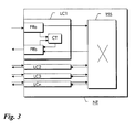
- FIG 3 shows an embodiment for a network node NE capable of supporting the above described delay measurement.
- the network node NE has a number of line cards LC1-LCn for optical transport signals and a switch matrix TSS capable of switching optical data units ODUk in time and space domain between any of the line cards LC1-LCn.
- Line cards contain input port and corresponding output port for a bidirectional link.
- Line card LC1 is shown exemplarily in more detail. It contains a framer FRa for received signals and a framer FRb for transmit signals.
- a start/stop counter CT is used to determine the insertion time for delay measurement signals.
- a trigger is sent from framer FRa to start counter CT.
- the DMp byte in the next transmit frame will be inverted by framer FRb.
- framer FRb gives a second trigger to stop counter CT.
- the count value of counter CT determines the insertion time, which will be inserted by framer FRb 256 frames later in reverse direction towards the initiating network node.
- Counter CT can have the same count granularity that is used to indicate the insertion time and can then be directly used as insertion time value. Otherwise, it must be scaled to the appropriate granularity of the insertion time value.
- the insertion delay can be determined as the relative frame phase between frames in receive and transmit directions.
- the start/stop counter can therefore be triggered also through other overhead bytes of the ODUk of which the delay is measured. Due to the consecutive nature of frames in a framed transport signal , it is also possible to use as insertion time the relative frame phase of the previous frame.
- the delay measurement can be implemented with conventional network nodes using the controllers residing on the respective line cards for controlling functionality of just these line cards.
- the delay measurement can also be implemented using a central controller or a shelf controller of the network nodes, or in cooperation between two or more controllers of the network nodes.
- the described method allows more precise measurement of delays in OTN networks, with greatly reduced measurement jitter and improved granularity.
- the resulting improvements can avoid route flapping in dynamic networks with latency based routing, plus improved options to characterize delay properties of network elements and their components.
- the high precision delay measurement will also enable use of OTN paths for mobile backhauling between remote radio equipment and radio equipment control using the Common Public Radio Interface (CPRI) defined through by the CPRI industry consortium, which requires tight delay control.
- CPRI Common Public Radio Interface
- the above described delay measurement can also be used for simplified calibration and characterization of network element delay properties, including FEC implementations, transfer delays through equipment components such as mappers, switching matrices etc.
- program storage devices e.g., digital data storage media, which are machine or computer readable and encode machine-executable or computer-executable programs of instructions, wherein said instructions perform some or all of the steps of said above-described methods.
- the program storage devices may be, e.g., digital memories, magnetic storage media such as a magnetic disks and magnetic tapes, hard drives, or optically readable digital data storage media.
- the embodiments are also intended to cover computers programmed to perform said steps of the above-described methods.
Landscapes
- Engineering & Computer Science (AREA)
- Computer Networks & Wireless Communication (AREA)
- Signal Processing (AREA)
- Physics & Mathematics (AREA)
- Electromagnetism (AREA)
- Data Exchanges In Wide-Area Networks (AREA)
Abstract
Description
- The present invention relates to the field of telecommunications and more particularly to a method and related network element for providing delay measurement in an optical transport network.
- In an optical network, network elements are physically interconnected through optical fiber links. Optical transport signals transmitted over the links are structured into consecutive frames, which repeat with a predefined frame rate.
- A connection for the transmission of data signals from end to end through an optical network is referred to as a path and represented by a multiplex unit repeatedly contained in each subsequent frame, such as for example an Optical Data Unit of size k (ODUk) for the Optical Transport Network according to ITU-T G.709. An ODUk has a payload and an overhead portion.
- A segment of a path is referred to as a Tandem Connection and exists, when established, for monitoring purposes and has its own Tandem Connection Monitoring (TCM) overhead field in the ODUk overhead.
- The ITU recommendation G.709 defines in chapters 15.8.2.1.6 for a path and 15.8.2.2.8 for a path segment a delay measurement using predefined overhead bytes in the ODUk overhead, with separate bits being defined for path delay measurement and for path segment delay measurement. A delay measurement signal consists of a constant value that is inverted at the beginning of a two-way delay measurement test. The new value of the delay measurement signal is maintained until the start of the next delay measurement test.
- To carry out a delay measurement, the originating network node inserts the inverted delay measurement signal into a defined subfield of the ODUk overhead and sends it to the far-end network node. The far-end network node upon detection of an inversion of the delay measurement signal in the defined subfield, loops back the inverted delay measurement signal towards the originating network node. The originating network node measures the number of frame periods between the moment the delay measurement signal value is inverted and the moment this inverted delay measurement signal value is received back from the far-end network node.
- According to the delay measurement defined in ITU-T G.709, the delay measurement signal can only be inserted at a specific location within the frame overhead. Since the signals that travel on a bidirectional link in opposite directions are asynchronous and have no fixed phase relationship of their frame phases, the far end node, when it detects a delay measurement signal, has to wait for the specific overhead location until it can invert the delay measurement signal in reverse direction. This causes a low granularity and high jitter of the measured delay value. For an ODU0, this translates into an imprecision of up to 100 µsec, corresponding 20km fiber length. It is hence an object to provide an improved delay measurement with a higher precision and lower jitter.
- These and other objects that appear below are achieved by delay measurement method of a path or path segment through a transport network and a corresponding network node for performing the delay measurement. An originating network node inserts a delay measurement request signal into an overhead subfield of a first data unit and transmits the first data unit over the path or path segment to a far-end network node as part of framed transport signals. The far-end network node, upon detection of the delay measurement request, inserts a delay measurement reply signal into an overhead subfield of a second data unit and transmits the second data unit back to the originating network node using framed transport signals in reverse direction. This second data unit represents the backward direction of the same path P, as the first data unit represents the forward direction of the same bidirectional path P. The originating network node determines a time difference between insertion of the delay measurement request signal and receipt of the delay measurement reply signal. The far-end network node further determines an insertion time value indicative of a time difference between receipt of the delay measurement request signal and insertion of the delay measurement reply signal in reverse direction and communicates the insertion time value back to the originating network node. The originating network node then determines a delay value for the path or path segment from the determined response time difference and the received insertion time value.
- Preferred embodiments of the present invention will now be described with reference to the accompanying drawings in which
- figure 1
- shows the principle of a loop back delay measurement along a bidirectional path through an optical network;
- figure 2
- shows different values for an insertion delay between transport frames in opposite directions; and
- figure 3
- shows a block diagram of a network element implementing the delay measurement.
- The principle of a loop back delay measurement is shown schematically in
figure 1 . Two network elements NE1, NE2 are connected over a bidirectional path P. Path P is a sequence of optical links and may lead through a number of intermediate network elements, which are not shown for the sake of simplicity. The path is represented by an optical data unit ODUk. Such optical data units are transported in multiplexed form within a framed transport signal, which contains consecutive transport frames that repeat with a predefined, fixed frame rate. The transport frames are termed Optical Transport Unit of size k (OTUk). The optical data units can be for example an ODU0 that repeats approximately every 100 µsec (more precisely every 98,4 µsec according to ITU-T recommendation G.709, table 7-4). - Each ODUk has an overhead section which includes a path monitoring (PM) field as described in ITU-T G.709 chapter 15.8.2.1 and figure 15-13. The PM field contains a subfield for path delay measurement (DMp).
- It is assumed in
figure 1 that network element NE1 starts a delay measurement by inserting a request signal REQ into the delay measurement subfield. Upon receipt, network element NE2 replies to the requested path measurement by inserting a reply message REP into the delay measurement subfield of the next ODUk in reverse direction. Network element NE1 measures the time difference between inserting the request message REQ and receipt of the reply message REP. - According to G.709, the DMp signal consists of a constant value (0 or 1) that is inverted at the beginning of a two-way delay measurement test. The transition from 0→1 in the sequence ...0000011111..., or the transition from 1→0 in the sequence ... 1111100000... represents the path delay measurement start point and corresponds to the request message REQ in
figure 1 . The new value of the DMp signal is maintained until the start of the next delay measurement test. - This DMp signal is inserted by the DMp originating network element NE1 and sent to the far-end network element NE2. This far-end network element NE2 loops back the inverted DMp signal towards the originating network element NE1. The looped-back, inverted DMp signal corresponds to the reply message REP in
figure 1 . - The originating network element NE1 measures the number of frame periods between the moment the DMp signal value is inverted and the moment this inverted DMp signal value is received back from the far-end network element NE2 to determine a round trip delay.
- Since bidirectional paths are typically symmetric in the two directions, the round trip delay equals twice the path delay. For other applications, only the total round trip delay as such is needed, so that theoretically possible asymmetries are not relevant.
- Apparently, an inversion of the DMp signal in reverse direction can be done only when the appropriate ODUk/ODUkT overhead position is sent out in backward direction, which can take up to 100 µsec for an ODU0. This causes a relatively low granularity of the delay measurement and high jitter of up to 100 µsec.
- Since the looping back network element NE2 knows the relative phase difference between forward and backward ODUk frames at the time the inversion is detected in forward direction, it can compute the time needed until the inversion is inserted into the backward direction.
- Therefore, according to the present embodiment, network element NE2 sends in addition to or as part of the reply message REP a value indicating the time between reception of the inversion in forward direction and insertion of the inversion into reverse direction.
- This value can be for example a one byte value, which specifies the insertion time in n times 0,5 µsec, allowing to specify any time between 0 and 128 µsec with 0,5 µsec granularity. In the preferred embodiment, however, the value n is a two byte value which indicates the insertion time with a granularity of in n times 0,1 µsec.
- The value that indicates the insertion time can in principle be sent through any available channel. For example, the value can use a reserved field in the ODU overhead, which is available for proprietary or future use. However, it is preferable to re-use the existing DM subfield for this purpose. The DM subfield has a length of one bit per ODU, separately for path and for path segment delay measurements, and repeats every ODU. Thus, the DM subfields from consecutive ODUs can be used for the transport of the insertion time value.
- In order to ensure backwards compatibility, the following changes to the existing delay measurement protocol in the DM subfield are proposed:
- No change of protocol in forward direction, i.e. towards the looping NE.
- In backward direction
- the inverted pattern is sent as usual for 256 bits constantly (other values than 256 could be chosen as long as the value is fixed),
- followed by the two byte value indicating the time between reception of the inversion in forward direction and insertion of the inversion into backward direction (specified in units of 0,1 µsec),
- followed by a one-byte checksum of the previous byte to ensure reliability against bit errors,
- followed by the constant inverted pattern identical to the first 256 bits after inversion.
- The proposed protocol is backward compatible in all mixed scenarios of network elements supporting and not supporting the protocol amendment:
- In case the triggering network element does not support this feature it simply ignores the two byte time value and following checksum inserted by the looping back network element, thus giving a delay measurement with current G.709 precision.
- In case the looping back network element does not support this feature it does not insert the time value and checksum. This is detected by the triggering network element based on checksum mismatch, so it will not use the time value and provide again a measurement result with current G.709 precision. In addition, it can indicate to the user of the delay measurement that the measurement result has today's imprecision constraints.
-
Figure 2 shows schematically the insertion time for three measurement cycles. Network node NE2 receives frame F1 with the DMp bit inverted, indicating a request for a delay measurement. The receipt of the inverted DMp bit starts the determination of the insertion time. The next frame in reverse direction RF1 is sent at a time t1 thereafter and network element NE2 inverts the DMp byte of RF1 accordingly. The insertion time t1 is communicated to the originating network element NE1, hence. - Some time later, network element NE2 receives another frame F2 having its DMp byte inverted again, thus triggering a second delay measurement. Due to the asynchronous nature of the two directions of bidirectional paths in optical signals, the frame phase of the next frame in reverse direction RF2 has become larger, now. The insertion time t2 until the next DMp can be inverted in reverse direction is communicated again to originating network node NE1.
- Even some time later, network node NE2 receives a frame F3 with its DMp byte inverted again. In reverse direction, the last frame RF3a has just been sent, so that the invertion in reverse direction can only be made in the next frame RF3b. The insertion time t3 is now close to the duration of one frame length, i.e. close to 100 µsec for an ODU0.
-
Figure 3 shows an embodiment for a network node NE capable of supporting the above described delay measurement. The network node NE has a number of line cards LC1-LCn for optical transport signals and a switch matrix TSS capable of switching optical data units ODUk in time and space domain between any of the line cards LC1-LCn. Line cards contain input port and corresponding output port for a bidirectional link. - Line card LC1 is shown exemplarily in more detail. It contains a framer FRa for received signals and a framer FRb for transmit signals. A start/stop counter CT is used to determine the insertion time for delay measurement signals. When an ODUk is received which has its DMp byte inverted, a trigger is sent from framer FRa to start counter CT. As a consequence, the DMp byte in the next transmit frame will be inverted by framer FRb. When this happens, framer FRb gives a second trigger to stop counter CT. The count value of counter CT determines the insertion time, which will be inserted by framer FRb 256 frames later in reverse direction towards the initiating network node.
- Counter CT can have the same count granularity that is used to indicate the insertion time and can then be directly used as insertion time value. Otherwise, it must be scaled to the appropriate granularity of the insertion time value.
- While the present embodiment uses the delay measurement subfield DMp of the path monitoring field, the same can be applied also to the delay measurement subfield DMti, i=1 to 6, of any of the six tandem connection monitoring overhead fields TCMi, i=1 to 6 within the ODUk overhead, see ITU-T G.709 chapter 15.8.2.2.
- Since the delay measurement subfield is always in the same position within each subsequent frame, the insertion delay can be determined as the relative frame phase between frames in receive and transmit directions. The start/stop counter can therefore be triggered also through other overhead bytes of the ODUk of which the delay is measured. Due to the consecutive nature of frames in a framed transport signal , it is also possible to use as insertion time the relative frame phase of the previous frame.
- The delay measurement can be implemented with conventional network nodes using the controllers residing on the respective line cards for controlling functionality of just these line cards. Alternatively, the delay measurement can also be implemented using a central controller or a shelf controller of the network nodes, or in cooperation between two or more controllers of the network nodes.
- The described method allows more precise measurement of delays in OTN networks, with greatly reduced measurement jitter and improved granularity. The resulting improvements can avoid route flapping in dynamic networks with latency based routing, plus improved options to characterize delay properties of network elements and their components.
- The high precision delay measurement will also enable use of OTN paths for mobile backhauling between remote radio equipment and radio equipment control using the Common Public Radio Interface (CPRI) defined through by the CPRI industry consortium, which requires tight delay control.
- The above described delay measurement can also be used for simplified calibration and characterization of network element delay properties, including FEC implementations, transfer delays through equipment components such as mappers, switching matrices etc.
- The description and drawings merely illustrate the principles of the invention. It will thus be appreciated that those skilled in the art will be able to devise various arrangements that, although not explicitly described or shown herein, embody the principles of the invention and are included within its spirit and scope. Furthermore, all examples recited herein are principally intended expressly to be only for pedagogical purposes to aid the reader in understanding the principles of the invention and the concepts contributed by the inventors to furthering the art, and are to be construed as being without limitation to such specifically recited examples and conditions. Moreover, all statements herein reciting principles, aspects, and embodiments of the invention, as well as specific examples thereof, are intended to encompass equivalents thereof.
- A person of skill in the art would readily recognize that steps of various above-described methods can be performed by programmed computers. Herein, some embodiments are also intended to cover program storage devices, e.g., digital data storage media, which are machine or computer readable and encode machine-executable or computer-executable programs of instructions, wherein said instructions perform some or all of the steps of said above-described methods. The program storage devices may be, e.g., digital memories, magnetic storage media such as a magnetic disks and magnetic tapes, hard drives, or optically readable digital data storage media. The embodiments are also intended to cover computers programmed to perform said steps of the above-described methods.
Claims (10)
- A delay measurement method of a path (P) or path segment through a transport network, comprising- at an originating network node (N1) inserting a delay measurement request signal (REQ) into an overhead subfield of a first data unit and transmitting said first data unit over said path (P) or path segment to a far-end network node (NE2) as part of framed transport signals;- at said far-end network node (NE2), upon detection of said delay measurement request (REQ), inserting a delay measurement reply signal (REP) into an overhead subfield of a second data unit and transmitting said second data unit back to said originating network node (NE1) using framed transport signals in reverse direction;- at said originating network node (NE1) determining a response time difference between the insertion of said delay measurement request signal (REQ) and receipt of said delay measurement reply signal (REP);further comprising:- at said far-end network node (NE2), determining an insertion time value indicative of a time difference (t1, t2, t3) between receipt of said delay measurement request signal (REQ) and insertion of said delay measurement reply signal (REP) in reverse direction and communication said insertion time value to said originating network node; and- at said originating network node (NE1) determining a delay value for said path (P) or path segment from said determined response time difference and said received insertion time value.
- A method according to claim 1, wherein a constant value is transmitted in said overhead subfield of subsequent data units and wherein to transmit said delay measurement request signal or said delay measurement reply signal, said constant value is inverted.
- A method according to claim 2, wherein said far-end network node (NE2) sends the inverted constant value for a predefined number of subsequent data units followed by one or more data units carrying said insertion time value in said overhead subfield.
- A method according to claim 3, wherein said far-end network node (NE2) after insertion of said time value sends a checksum value in said overhead subfield of a subsequent data unit.
- A method according to claim 1, wherein said insertion time value is determined as a relative frame phase between transport frames in receive (F1, F2; F3) and transmit (RF1, RF2, RFb) direction.
- A network node (NE1) for a transport network, comprising at least one input and one output for receiving and transmitting, respectively, framed transport signals carrying one or more data units; wherein said network node (NE1) is adapted to perform a delay measurement of a path (P) or path segment by- inserting a delay measurement request signal (REQ) into an overhead subfield of a first data unit and transmitting said first data unit as part of a framed transport signal at said output;- receiving at said input a framed transport signal in reverse direction transporting a second data unit having within an overhead subfield a delay measurement reply signal (REP);- determining a response time difference between the insertion of said delay measurement request signal (REQ) and receipt of said delay measurement reply signal (REP);- receiving an insertion time value indicative of a time difference (t1, t2, t3) between a receipt of said delay measurement request signal (REQ) and an insertion of said delay measurement reply signal (REP) at a remote network node (NE2); and- determining a delay value for said path (P) or path segment from said determined response time difference and said received insertion time value.
- A network node (NE1) according to claim 6 being adapted to detect when no insertion time value is received and if so, to determine said value for said path or path segment from said determined response time difference, only.
- A network node (NE1) according to claim 7 being adapted to detect a missing insertion time value by means of a checksum check.
- A network node (NE1) according to claim 7 being adapted to provide in the case of a missing insertion time value along with said delay value an indication that said delay value is of a lower precision.
- A network node (NE2) for a transport network, comprising at least one input and one output for receiving and transmitting, respectively, framed transport signals carrying one or more data units; wherein said network node (NE2) is adapted to support a delay measurement of a path (P) or path segment by- receiving at said input a framed transport signal transporting a first data unit having within an overhead subfield a delay measurement request signal (REQ);- upon detection of said delay measurement request signal (REQ), inserting a delay measurement reply signal (REP) into an overhead subfield of a second data unit and transmitting said second data unit at said output as part of a framed transport signal in reverse direction;- determining an insertion time value indicative of a time difference (t1, t2, t3) between receipt of said delay measurement request signal (REQ) and insertion of said delay measurement reply signal (REP) in reverse direction and communicating said insertion time value to an originating network node (NE1).
Priority Applications (6)
| Application Number | Priority Date | Filing Date | Title |
|---|---|---|---|
| EP11306605.4A EP2600546A1 (en) | 2011-12-02 | 2011-12-02 | Method and Related Network Element Providing Delay Measurement in an Optical Transport Network |
| KR1020147017618A KR20140105789A (en) | 2011-12-02 | 2012-10-17 | Method and related network element providing delay measurement in an optical transport network |
| JP2014543819A JP5833253B2 (en) | 2011-12-02 | 2012-10-17 | Method and related network element for providing delay measurement of an optical transmission network |
| US14/356,303 US20140270754A1 (en) | 2011-12-02 | 2012-10-17 | Method and related network element providing delay measurement in an optical transport network |
| CN201280058119.3A CN103959687A (en) | 2011-12-02 | 2012-10-17 | Method and related network element providing delay measurement in an optical transport network |
| PCT/EP2012/070564 WO2013079255A1 (en) | 2011-12-02 | 2012-10-17 | Method and related network element providing delay measurement in an optical transport network |
Applications Claiming Priority (1)
| Application Number | Priority Date | Filing Date | Title |
|---|---|---|---|
| EP11306605.4A EP2600546A1 (en) | 2011-12-02 | 2011-12-02 | Method and Related Network Element Providing Delay Measurement in an Optical Transport Network |
Publications (1)
| Publication Number | Publication Date |
|---|---|
| EP2600546A1 true EP2600546A1 (en) | 2013-06-05 |
Family
ID=47022700
Family Applications (1)
| Application Number | Title | Priority Date | Filing Date |
|---|---|---|---|
| EP11306605.4A Withdrawn EP2600546A1 (en) | 2011-12-02 | 2011-12-02 | Method and Related Network Element Providing Delay Measurement in an Optical Transport Network |
Country Status (6)
| Country | Link |
|---|---|
| US (1) | US20140270754A1 (en) |
| EP (1) | EP2600546A1 (en) |
| JP (1) | JP5833253B2 (en) |
| KR (1) | KR20140105789A (en) |
| CN (1) | CN103959687A (en) |
| WO (1) | WO2013079255A1 (en) |
Cited By (4)
| Publication number | Priority date | Publication date | Assignee | Title |
|---|---|---|---|---|
| CN105515908A (en) * | 2015-12-10 | 2016-04-20 | 中国航空工业集团公司西安航空计算技术研究所 | AFDX photoelectric conversion time delay test method |
| CN105553544A (en) * | 2015-12-08 | 2016-05-04 | 中国航空工业集团公司西安航空计算技术研究所 | AFDX photoelectric converter testing method |
| EP3082281A4 (en) * | 2013-12-13 | 2016-10-26 | Zte Corp | METHOD FOR TRANSMISSION DELAY MEASUREMENT OF OPTICAL TRANSPORT NETWORK DEVICE AND SOURCE OTN DEVICE |
| CN109005476A (en) * | 2018-08-01 | 2018-12-14 | 贵州电网有限责任公司 | OTN routing optimization method is netted by province based on OSNR |
Families Citing this family (10)
| Publication number | Priority date | Publication date | Assignee | Title |
|---|---|---|---|---|
| US9473261B1 (en) | 2013-08-29 | 2016-10-18 | Microsemi Storage Solutions (U.S.), Inc. | System and method to achieve datapath latency symmetry through an OTN wrapper |
| CN106031134A (en) * | 2014-02-26 | 2016-10-12 | 三菱电机株式会社 | Light transport system and delay measurement method |
| KR101693415B1 (en) * | 2015-02-23 | 2017-01-05 | 충북대학교 산학협력단 | Running Measuring Device and Running Measuring Method with Correction of Time-Delay using Backward Running |
| JP6101306B2 (en) * | 2015-06-05 | 2017-03-22 | 日本電信電話株式会社 | Optical transmission apparatus and optical transmission method |
| CN111052632A (en) * | 2017-09-07 | 2020-04-21 | 华为技术有限公司 | A method, device and system for time delay measurement in an optical transport network |
| US10892967B2 (en) * | 2018-12-21 | 2021-01-12 | Cisco Technology, Inc. | End-to-end path delay measurements in a network |
| CN110649964B (en) * | 2019-11-14 | 2024-01-16 | 桂林聚联科技有限公司 | Method for measuring optical fiber time delay |
| US11431425B2 (en) * | 2020-09-24 | 2022-08-30 | Corning Research & Development Corporation | Measuring an end-to-end delay(s) in a distributed communications system |
| EP4427361A1 (en) * | 2021-11-04 | 2024-09-11 | Telefonaktiebolaget LM Ericsson (publ) | Optical fiber link delay measurement |
| US12261641B2 (en) | 2022-11-18 | 2025-03-25 | Cisco Technology, Inc. | Delay measurement for hybrid packet and optical transport networks |
Family Cites Families (13)
| Publication number | Priority date | Publication date | Assignee | Title |
|---|---|---|---|---|
| US20050058081A1 (en) * | 2003-09-16 | 2005-03-17 | Elliott Brig Barnum | Systems and methods for measuring the distance between devices |
| US7475272B2 (en) * | 2005-09-09 | 2009-01-06 | International Business Machines Corporation | Method for calculating clock offset and skew |
| JP2007089065A (en) * | 2005-09-26 | 2007-04-05 | Mitsubishi Electric Corp | Point / multipoint optical transmission system and master station apparatus |
| US7577169B1 (en) * | 2005-11-30 | 2009-08-18 | The United States Of America As Represented By The Secretary Of The Navy | Time stamping |
| US7809027B2 (en) * | 2006-09-25 | 2010-10-05 | Futurewei Technologies, Inc. | Network clock synchronization floating window and window delineation |
| US8295310B2 (en) * | 2006-09-25 | 2012-10-23 | Futurewei Technologies, Inc. | Inter-packet gap network clock synchronization |
| US8121111B2 (en) * | 2007-03-29 | 2012-02-21 | Verizon Patent And Licensing Inc. | Method and system for measuring latency |
| CN101330374B (en) * | 2007-06-18 | 2012-11-14 | 大唐移动通信设备有限公司 | Method and system for synchronizing clock of transmission network as well as subordinate clock side entity |
| JP2011087173A (en) * | 2009-10-16 | 2011-04-28 | Fujitsu Telecom Networks Ltd | Pon system and position monitoring control method |
| US9485050B2 (en) * | 2009-12-08 | 2016-11-01 | Treq Labs, Inc. | Subchannel photonic routing, switching and protection with simplified upgrades of WDM optical networks |
| US8880684B2 (en) * | 2010-07-23 | 2014-11-04 | Broadcom Corporation | Method and system for measuring individual network round-trip delays in IP gateways |
| US9608755B2 (en) * | 2011-02-23 | 2017-03-28 | Ciena Corporation | Network element clock synchronization systems and methods using optical transport network delay measurement |
| CN102098155B (en) * | 2011-03-18 | 2013-11-13 | 北京国智恒电力管理科技有限公司 | Method for realizing sub-microsecond synchronization accuracy based on PTP (Precision Time Protocol) |
-
2011
- 2011-12-02 EP EP11306605.4A patent/EP2600546A1/en not_active Withdrawn
-
2012
- 2012-10-17 KR KR1020147017618A patent/KR20140105789A/en not_active Withdrawn
- 2012-10-17 JP JP2014543819A patent/JP5833253B2/en not_active Expired - Fee Related
- 2012-10-17 WO PCT/EP2012/070564 patent/WO2013079255A1/en not_active Ceased
- 2012-10-17 CN CN201280058119.3A patent/CN103959687A/en active Pending
- 2012-10-17 US US14/356,303 patent/US20140270754A1/en not_active Abandoned
Non-Patent Citations (2)
| Title |
|---|
| FREIBERGER M ET AL: "Demonstration of a novel method for real-time network latency measurements in the optical transport network using G.709 overhead", OPTICAL FIBER COMMUNICATION - INCUDES POST DEADLINE PAPERS, 2009. OFC 2009. CONFERENCE ON, IEEE, PISCATAWAY, NJ, USA, 22 March 2009 (2009-03-22), pages 1 - 3, XP031467628, ISBN: 978-1-4244-2606-5 * |
| JONGYOON SHIN ETRI KOREA (REPUBLIC OF): "Enhanced delay measurement for OTN;C 1705", ITU-T DRAFTS ; STUDY PERIOD 2009-2012, INTERNATIONAL TELECOMMUNICATION UNION, GENEVA ; CH, vol. Study Group 15 ; 11/15, 21 November 2011 (2011-11-21), pages 1 - 4, XP017568678 * |
Cited By (5)
| Publication number | Priority date | Publication date | Assignee | Title |
|---|---|---|---|---|
| EP3082281A4 (en) * | 2013-12-13 | 2016-10-26 | Zte Corp | METHOD FOR TRANSMISSION DELAY MEASUREMENT OF OPTICAL TRANSPORT NETWORK DEVICE AND SOURCE OTN DEVICE |
| US10361938B2 (en) | 2013-12-13 | 2019-07-23 | Zte Corporation | Method for measuring transmission delay of optical transport network device and source OTN device |
| CN105553544A (en) * | 2015-12-08 | 2016-05-04 | 中国航空工业集团公司西安航空计算技术研究所 | AFDX photoelectric converter testing method |
| CN105515908A (en) * | 2015-12-10 | 2016-04-20 | 中国航空工业集团公司西安航空计算技术研究所 | AFDX photoelectric conversion time delay test method |
| CN109005476A (en) * | 2018-08-01 | 2018-12-14 | 贵州电网有限责任公司 | OTN routing optimization method is netted by province based on OSNR |
Also Published As
| Publication number | Publication date |
|---|---|
| KR20140105789A (en) | 2014-09-02 |
| US20140270754A1 (en) | 2014-09-18 |
| WO2013079255A1 (en) | 2013-06-06 |
| CN103959687A (en) | 2014-07-30 |
| JP5833253B2 (en) | 2015-12-16 |
| JP2015504639A (en) | 2015-02-12 |
Similar Documents
| Publication | Publication Date | Title |
|---|---|---|
| EP2600546A1 (en) | Method and Related Network Element Providing Delay Measurement in an Optical Transport Network | |
| EP3531588B1 (en) | Method and device for building flexible ethernet group | |
| KR101481396B1 (en) | Method for synchronizing master and slave clocks of packet-switched network with aggregated connections between nodes, and associated synchronization devices | |
| CN103155488B (en) | Delay measurements system and delay measuring method and delay measurements equipment and delay measurements program | |
| JP6519162B2 (en) | Transmission system, transmission time difference measurement method in transmission system, and node | |
| EP2495918A1 (en) | Method, system and node device for establishing label switch path | |
| US11223422B2 (en) | Method and apparatus for processing ethernet data in optical network, and system | |
| EP2254276A1 (en) | Method for signalling of data transmission path properties to a non-OAM observent client | |
| CN110100397B (en) | Delay measurement method and site | |
| US9054824B2 (en) | Inter-frame gap controller, traffic transmitter, transmission apparatus and inter-frame gap control method | |
| JP2014212407A (en) | Transmission device and path switching method | |
| CN109565344B (en) | System and method for determining propagation delay | |
| JP2012527808A5 (en) | ||
| EP2630752B1 (en) | Layer one path delay compensation | |
| CN111052632A (en) | A method, device and system for time delay measurement in an optical transport network | |
| CN114844804B (en) | Network measurement method, system, electronic device and computer readable storage medium | |
| CN105656587B (en) | A method and apparatus for realizing time slot synchronization | |
| CN106031134A (en) | Light transport system and delay measurement method | |
| EP3130184A1 (en) | Methods and nodes for transmission of a synchronous data over packet data network | |
| JP4412068B2 (en) | Uninterruptible switching system, uninterruptible switching method, and communication station used therefor | |
| US8848720B2 (en) | Method and apparatus for determining propagation delay in a network | |
| US20180234315A1 (en) | Data division unit, communication device, communication system, data division method, and storage medium having data division program stored therein | |
| KR20130056820A (en) | Apparatus and method for measuring delay |
Legal Events
| Date | Code | Title | Description |
|---|---|---|---|
| PUAI | Public reference made under article 153(3) epc to a published international application that has entered the european phase |
Free format text: ORIGINAL CODE: 0009012 |
|
| AK | Designated contracting states |
Kind code of ref document: A1 Designated state(s): AL AT BE BG CH CY CZ DE DK EE ES FI FR GB GR HR HU IE IS IT LI LT LU LV MC MK MT NL NO PL PT RO RS SE SI SK SM TR |
|
| AX | Request for extension of the european patent |
Extension state: BA ME |
|
| 111Z | Information provided on other rights and legal means of execution |
Free format text: AL AT BE BG CH CY CZ DE DK EE ES FI FR GB GR HR HU IE IS IT LI LT LU LV MC MK MT NL NO PL PT RO RS SE SI SK SM TR Effective date: 20130410 |
|
| 17P | Request for examination filed |
Effective date: 20131126 |
|
| RBV | Designated contracting states (corrected) |
Designated state(s): AL AT BE BG CH CY CZ DE DK EE ES FI FR GB GR HR HU IE IS IT LI LT LU LV MC MK MT NL NO PL PT RO RS SE SI SK SM TR |
|
| RAP1 | Party data changed (applicant data changed or rights of an application transferred) |
Owner name: ALCATEL LUCENT |
|
| D11X | Information provided on other rights and legal means of execution (deleted) | ||
| STAA | Information on the status of an ep patent application or granted ep patent |
Free format text: STATUS: THE APPLICATION HAS BEEN WITHDRAWN |
|
| 18W | Application withdrawn |
Effective date: 20160901 |