EP2600495A1 - Cooling conduits provided in a stack of stator segments - Google Patents
Cooling conduits provided in a stack of stator segments Download PDFInfo
- Publication number
- EP2600495A1 EP2600495A1 EP11191729.0A EP11191729A EP2600495A1 EP 2600495 A1 EP2600495 A1 EP 2600495A1 EP 11191729 A EP11191729 A EP 11191729A EP 2600495 A1 EP2600495 A1 EP 2600495A1
- Authority
- EP
- European Patent Office
- Prior art keywords
- plate
- opening
- plural
- circumferential
- shape
- Prior art date
- Legal status (The legal status is an assumption and is not a legal conclusion. Google has not performed a legal analysis and makes no representation as to the accuracy of the status listed.)
- Granted
Links
Images



Classifications
-
- H—ELECTRICITY
- H02—GENERATION; CONVERSION OR DISTRIBUTION OF ELECTRIC POWER
- H02K—DYNAMO-ELECTRIC MACHINES
- H02K1/00—Details of the magnetic circuit
- H02K1/06—Details of the magnetic circuit characterised by the shape, form or construction
- H02K1/12—Stationary parts of the magnetic circuit
- H02K1/20—Stationary parts of the magnetic circuit with channels or ducts for flow of cooling medium
-
- H—ELECTRICITY
- H02—GENERATION; CONVERSION OR DISTRIBUTION OF ELECTRIC POWER
- H02K—DYNAMO-ELECTRIC MACHINES
- H02K1/00—Details of the magnetic circuit
- H02K1/06—Details of the magnetic circuit characterised by the shape, form or construction
- H02K1/12—Stationary parts of the magnetic circuit
- H02K1/16—Stator cores with slots for windings
-
- H—ELECTRICITY
- H02—GENERATION; CONVERSION OR DISTRIBUTION OF ELECTRIC POWER
- H02K—DYNAMO-ELECTRIC MACHINES
- H02K1/00—Details of the magnetic circuit
- H02K1/06—Details of the magnetic circuit characterised by the shape, form or construction
- H02K1/12—Stationary parts of the magnetic circuit
- H02K1/14—Stator cores with salient poles
- H02K1/146—Stator cores with salient poles consisting of a generally annular yoke with salient poles
- H02K1/148—Sectional cores
Definitions
- the present invention relates to an arrangement for an electrical machine, in particular to a stator segment, wherein a cooling conduct system is provided within the arrangement, wherein the arrangement is formed by stacking a plurality of plates.
- a stator for an electrical machine such as a generator or a motor, may comprise an annular structure for holding plural coils using protrusions or teeth of the stator extending radially inwards or outwards.
- the stator may be made of material with high magnetic permeability to focus magnetic field lines within the material of the stator, when a current flows through the coils supported by the stator support structure.
- Radially inwards or radially outwards a rotor may be arranged comprising a plurality of permanent or electro magnets such that an air gap is formed between ends of the teeth of the stator construction and end of the magnets of the rotor.
- stator construction in particular for large power generators, may require cooling. It is conventionally known to cool a stator structure by air cooling and by liquid cooling.
- Document DE 10 2009 009 819 A1 discloses a packet of stator metal pieces for an electrical machine having plural cooling channels and cooling openings, wherein the cooling openings are radially and/or tangentially offset relative to each other in adjacent stator metal pieces.
- an arrangement, in particular stator segment, for an electric machine comprising: a stack of at least three (or between 100 and 10,000) of a plurality of plates having main planar (flat) surfaces, the surfaces extending in a circumferential direction to a larger extent than in a radial direction, wherein the plurality of plates comprises at least a first plate having a first through opening of a first shape, and a second plate having a second through opening of a second shape different from the first shape, wherein the at least three plates are bounded (in particular glued and/or laminated) at their main surfaces to form the stack such that a cooling conduit is formed inside the stack by at least partial overlap of the first through opening and the second through opening, wherein cooling fluid is guidable within the cooling conduit at least in the circumferential direction.
- the arrangement for the electric machine may for example be or comprise a stator or a stator segment spanning a particular circumferential range, such as spanning an angle range between 5° and 360°, in particular between 20° and 70°, in particular 30° or 60°.
- the electric machine may for example be or comprise an electric generator.
- the plates of the stack may be glued together or laminated together, wherein the plate may be stacked at their main planar surfaces such that boundary curves of the main planar surfaces align with each other (or are flush with each other).
- the plates may be stacked and laminated on top of each other (in particular electrically isolated from each other) in the axial direction perpendicular to the main planar surfaces of the plates.
- the plates may comprise iron or steel to provide an appropriate magnetic permeability for focusing magnetic field lines within the stack.
- the stack may be or may have been subjected to a pressure treatment (in particular exerting pressure perpendicular to main planar surfaces) and may be subjected or may have been subjected to a heat treatment within an oven to cure or crosslink glue or an adhesive placed between the plates at their respective main planar surfaces.
- a pressure treatment in particular exerting pressure perpendicular to main planar surfaces
- a heat treatment within an oven to cure or crosslink glue or an adhesive placed between the plates at their respective main planar surfaces.
- the plates having been assembled into the stack may be electrically isolated from each other.
- Each of the plates may have a much larger extension or extent or dimension or size in the circumferential direction and also in the radial direction than in a thickness direction, wherein the thickness direction is perpendicular to the main planar surfaces.
- the first through opening may comprise a round or circular shape and may be provided to establish a portion of a cooling conduit, wherein this portion of the cooling conduit provided by the first through openings may allow the cooling fluid to flow along an axial direction being perpendicular to the main planar surfaces of the plates.
- the first plate may in particular have exclusively one first through opening or may have a first through opening and another first through opening, wherein the first through opening and the other first through opening may be provided at opposite circumferential ends of the first plate.
- the second plate may have a same outer boundary as the first plate, such that when stacked on top of each other the outer boundary (line or curve) of the first plate matches or aligns with the outer boundary of the second plate.
- the second through opening may have a larger extent than the first through opening, in particular being at least 50 times to 200 times as large as the first through opening.
- the cooling conduit Upon stacking and/or laminating and/or gluing the at least three plates on top of each other the cooling conduit is formed inside the stack such that cooling fluid introduced into the cooling conduit is confined within the cooling conduit such that it is prohibited to run out of or leave the cooling conduit except at an entry port or an exit port (which may in particular provided by the first through opening and/or another first through opening contained within the first plate).
- the partial overlap of the first through opening and the second through opening allows a propagation of the cooling fluid (in particular cooling air or cooling liquid) at least partially in the axial direction, in order to reach from a plate to another plate stacked on top of this plate.
- the cooling channel is shaped by the shape of the first through opening and/or the second through opening such that the cooling fluid is conductable within the cooling conduit at least in the circumferential direction.
- the stack may for example comprise 200 to 10,000 plates, in particular between 1,000 and 5,000 plates.
- the thickness of the plates may amount to between 0.1 mm and 4 mm, in particular to between 0.5 mm and 2 mm, further in particular about 0.65 mm.
- the thickness of the stack in the axial direction may amount to between 0.2 m and 4 m, in particular to between 0.5 m and 3 m, in particular to about 2 m.
- a stator may be assembled having a radius between 0.5 m and 12 m, in particular between 3 m and 5 m, further in particular being around 4 m.
- the stator may be a generator stator having radially outwards protruding teeth and being adapted to operate together with an outer rotor.
- each plate comprises plural protrusions protruding radially (in particular outwards) for providing, when the stack is formed, plural teeth and slots alternating in the circumferential direction, wherein in particular a radial extent of the protrusions amounts to between 1/50 to 1/3, in particular between 1/20 and 1/5, of an extent of the plate in the circumferential direction.
- the plural protrusions may have a rectangular shape, at least approximately.
- Each plate may further comprise a circumferentially extending base from which the plural protrusions extend radially (in particular outwards). Thereby, plural coils may be supported by the laminated stack in order to provide a complete stator segment for an electric generator.
- the first plate has the first through opening, in particular provided to form an entry port for the cooling liquid, arranged at a first circumferential end of the first plate.
- cooling fluid in particular cooling air and/or cooling liquid
- cooling conduit may be introduced in the or into the cooling conduit from one circumferential end of the first plate via the first through opening of the first plate.
- an entry connector for connecting the entry port to a cooling tubing may be provided at the entry port of the first plate.
- the first plate may not contain or comprise any other opening in order to securely seal the cooling fluid from flowing out of the cooling conduit.
- the first plate has another first through opening, in particular provided to form an exit port for the cooling liquid, of the first plate, arranged at another circumferential end of the first plate.
- a first plate having a first through opening and another first through opening is used to form the stack one of the through openings may be blocked.
- a first plate having only one first through opening may be provided or used, wherein a bottom first plate and a top first plate may be switched in orientation such as to provide the entry port at a first circumferential end of the stack and provide the exit port at a second circumferential end of the stack.
- the first shape is round, in particular circular.
- manufacturing the first through opening may be simplified.
- smooth flow of the cooling liquid or cooling fluid within the first through holes may be enabled, since by stacking plural first plates on top of each other essentially a tubular cooling conduit may be formed within the first plates.
- the tubular cooling conduit may have a circular cross-section corresponding to the first shape.
- the first shape may be oval or rectangular or quadratic.
- an extent in the circumferential direction of each of the plates amounts to between 1,000 times and 10,000 times of a thickness of the plate perpendicular to the main surface.
- the second through opening extends in the circumferential direction between 50% and 99% of a circumferential extent of the second plate.
- a main portion of the circumferential extent of the second plate may be recessed (within a particular radial range), to provide at least a portion of the second through opening.
- a portion of the second shape at a circumferential end of the second plate corresponds to at least a portion of the first shape.
- plural first plates may be stacked on top of each other, then plural second plates may be stacked on top of the plural first plate and then first plural first plates may be stacked on the plural second plate in order to form the stack.
- the second plate has another second through opening of the first shape arranged at another circumferential end of the second plate.
- the second through opening comprises plural radially extending opening portions at respective plural circumferential positions, in particular corresponding to the plural protrusions, wherein, in particular, an extent of the radially extending opening portions in the radial direction amounts to between 10 times and 100 times of an extent of the radially extending portions in the circumferential direction.
- the plural radially extending opening portions may allow cooling of teeth of the arrangement, when configured as a stator or a stator segment.
- the plural radially extending opening portions may allow flow of the cooling fluid along the radial direction and/or the axial direction, when plural second plates are stacked on top of each other.
- the cooling effect of the cooling liquid flowing radially outwards and axially may be improved.
- the plurality of plates comprises a third plate having a plurality of third through openings of a third shape different from the second shape, the third through openings being in particular arranged at plural circumferential positions, in particular corresponding to the positions of the plural protrusions, the third through openings being in particular arranged at a same radial position, in particular corresponding to radial end portions of the plural protrusions.
- the third through openings within the third plate may allow a flow of the cooling liquid along the axial direction in order to allow a continuous cooling fluid flow within the cooling conduit. Thereby, effective exchange of the cooling fluid may be achieved in order to improve the heat transfer rate from the arrangement which is to be cooled.
- the arrangement is adapted such that the cooling fluid flows along an axial direction within the first through opening and/or the other first through opening, and/or along the circumferential direction within a circumferential portion of the first through opening, and/or along the radial direction and/or the axial direction within the radially extending portions of the second through opening, and/or along the axial direction within the third through opening.
- the cooling fluid flows exclusively along the axial direction within the first through opening and/or the other first through opening.
- the cooling fluid flows exclusively in the axial direction within the third through opening.
- an arrangement comprised by stacking plural first plate, plural second plate, at least one third plate, a mirrored plurality of second plates and a plurality of first plates may be repeated to form an even thicker stack, wherein the cooling liquid or fluid alternately flows along the circumferential direction than flows opposite to the circumferential direction, than flows again in the circumferential direction and so force.
- the entry port and the exit port are provided at a same circumferential end of the first plates.
- the second plate has plural second through openings of the second shape arranged along plural circumferential positions of the second plate.
- the plural second through openings according to this embodiment may have a same size, in particular comprising a rectangular size or shape.
- the second plate may not comprise a through opening extending along the circumferential direction but may instead comprise plural relatively small through openings, in order to improve the stiffness, strength or stability of the second plate.
- the number of second through openings in the second plate may amount to between 0.5 to 2.0 times a number of protrusions comprised in the second plate. Thereby, a stability of the second plate may be improved.
- the plurality of plates comprises another second plate having a plurality of other second through openings of the second shape, wherein the other second plate has the plural other second through openings arranged along plural other circumferential positions of the other second plate, the plural other circumferential positions being circumferentially offset relative to the plural circumferential positions of the second plate, when the second plate and the other second plate are stacked to form the stack, wherein outer boundaries of the main surfaces of the second plate and the other second plate align.
- the second through openings are circumferentially and/or radially offset relative to the other second through openings.
- cooling fluid may propagate in an axial direction from a second through opening in a bottom second plate to another second through opening in a top other second plate.
- a flow of the cooling fluid is enabled in the axial direction and/or in the circumferential direction due to the circumferential extent of the second through openings and the other second through openings.
- the other second through openings may have a same shape as the second through openings. Thereby, a manufacturing of the second plate may be simplified.
- the cooling fluid may propagate according to a zigzag movement or a wave type movement such as to alternate the moving direction axially but consistently propagating along a same circumferential direction.
- the cooling liquid flows within the second through openings and the other second through openings in the circumferential direction and/or in a first axial direction and in a second axial direction opposite to the axial direction in an alternating manner.
- the axial direction may be represented by a first axial direction corresponding to for example a positive direction of the axial direction and a second axial direction corresponding for example to a negative direction of the axial direction.
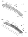
- Fig. 1 illustrates a first plate 100
- Fig. 2 illustrates a second plate 200
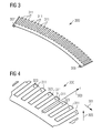
- Figs. 3 and 4 illustrate a third plate 300
- the first plate 100, the second plate 200 and the third plate 300 may be used to form an arrangement according to an embodiment of the present invention, in particular a stator segment for a generator, such as the stack 1000 illustrated in Fig. 10 .
- the first plate 100 illustrated in Fig. 1 forming a 60° sector of a circle extends in the circumferential direction 101 and also extends in the radial direction 103.
- a thickness of the plate 100 being measured perpendicular to the circumferential direction 101 and also perpendicular to the radial direction 103 may amount to about 0.65 mm, for example.
- the first plate 100 represents a 60° annular segment which together with the second plate 200 ( Fig. 2 ) and the third plate 300 ( Figs. 3 and 4 ) may form a stack 1000 ( Fig. 10 ) upon laminating a plurality of these plates, in order to form a stator segment spanning an angle interval of 60°.
- the axial direction is indicated by the arrow 105 in Figs. 1 to 4 .
- the first plate 100 comprises a first through opening 107 and another first through opening 109, wherein the first through opening 107 is arranged at a first circumferential end of the first plate 100 and the other first through opening 109 is arranged at the other circumferential end of the first plate 100.
- the first plate further comprises plural protrusions 111, which upon stacking plural plates on top of each other form plural teeth of the stator segment. Between the teeth 111 slots 113 will be formed upon stacking plural plates on top of each other.
- an entry port and/or an exit port may be formed, wherein upon stacking plural first plates on top of each other cooling fluid or liquid may propagate along the axial direction 105.
- the second plate 200 illustrated in Fig. 2 has a same outer boundary line as the first plate 100 illustrated in Fig. 1 .
- the second plate has a second through opening 215 which has a different shape than the first through opening of plate 100 illustrated in Fig. 1 .
- the second through opening 215 extends in the circumferential direction to an amount 1 which is about between 90% and 99% of an extent L of the second plate 200 in the circumferential direction 201.
- a portion 217 of the second through opening 215 corresponds to a portion of the first shape of the first through hole or through opening 107 of the first plate 100.
- liquid may propagate from the through opening 107 via the portion 217 into the second through opening 215 extending circumferentially.
- the cooling liquid or fluid may run along the circumferential direction 201.
- the second plate 200 illustrated in Fig. 2 comprises another second through opening 219 having the same shape as the shape of the first through opening 107 of the first plate 100, wherein the other second through opening is arranged at another circumferential end as the portion 217.
- the second through opening 215 comprises plural radially extending opening portions 221 and plural circumferential positions corresponding to the positions of the protrusions 111 or 211.
- the third plate 300 illustrated in Fig. 3 and in Fig. 4 has a same outer boundary line as the first plate 100 and the second plate 200 illustrated in Figs. 1 and 2 . Further, the third plate has two first through openings 307 and 309 at same positions as the first plate 100 has the first through openings 107 and 109. Further, as can be seen in the detailed view of Fig. 4 illustrating a portion of the third plate 300, the third plate 300 comprises a plurality of third through openings 323, which are arranged at plural circumferential positions corresponding to the positions of the plural protrusions 311. Thereby, the plural third through openings 323 are arranged at a same radial position r0. The plural third through openings 323 are provided to allow cooling liquid flow along the axial direction 305.
- Fig. 5 illustrates a method for assembling a stack of blades for providing a stator statement, in particular for a generator, according to an embodiment of the present invention.
- first plates 100 in particular five first plates 100, are stacked on top of each other.
- second step one or more, in particular three second plates 200 are stacked on top of the plural first plates.
- third plates 300 in particular one plate 300, is stacked on the plural second plates.
- mirrored second plates in particular three mirrored second plates, are stacked on top of the third plates.
- first plates 100 are stacked on top of the plural second plates.
- the mirrored second plate corresponds in shape to the second plate 200 but is in a different orientation obtained by rotating the second plate around the radial axis as indicated by reference 503 by an angle of 180°.
- a stack (such as stack 1000 illustrated in Fig. 10 ) may be formed which is bounded at the bottom and at the top by one or more first plates 100.
- an entry port 1007 for the cooling liquid may be provided and at the other of the first through opening an exit port 1009 of the cooling fluid may be provided, wherein the respective other first through opening may be blocked by a plug, for example.
- an entry tubing 525 and an exit tubing 527 are shown in Fig. 5 connecting to different first through openings of the first plates 100.
- the plural stacked first plates 100 will then allow fluid flow along the axial direction 505.
- the plural stacked second plates 200 will allow cooling fluid flow along the circumferential direction 501 and also along the radial direction 503 and partly also along the axial direction 505.
- the plural stacked third plates 300 will allow flow of the cooling fluid along the axial direction 503 within the end portions of the protrusions 511.
- the mirrored second plates 200 will allow fluid flow along the circumferential direction 501, the axial direction 503 and at least partially also along the axial direction 505.
- the plural first plates 100 will allow fluid flow along the axial direction 505 towards the exit port 509 which leads to the outlet tubing 527.
- Fig. 10 schematically illustrates an arrangement 1000 according to an embodiment of the present invention, which has been obtained by laminating a plurality of plates comprising the first plate 100, the second plate 200 and the third plate 300.
- the cooling fluid enters and at the exit port 1009 (the other through opening of the first plate 100) the cooling fluid exits the arrangement 1000.
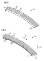
- Figs. 6, 7 and 8 illustrate a first plate, a second plate and another second plate, respectively, which may be utilized for assembling a stack to manufacture an arrangement according to an embodiment of the present invention.
- the first plate 600 illustrated in Fig. 6 corresponds to or is equal to the first plate 100 illustrated in Fig. 1 .
- the second plate 700 illustrated in Fig. 7 has a same outer boundary line as the first plate 600 illustrated in Fig. 6 and further comprises plural second through openings 715 which are arranged along the circumferential direction 701.
- the plural second through openings 715 have partly a rectangular size and are equally distributed across the circumferential width of the second plate 700.
- Further second through openings 714 are arranged which at least partially have a same size as the first through openings 607, 609 of the first plate 600.
- Fig. 8 illustrates another second plate 800 having a plurality of other second through openings 816 which have the same size as the plural second through openings 715 of the second plate 700 illustrated in Fig. 7 but which are circumferentially offset relative to the second through opening 715 of the second plate 700.
- the second through openings 715 do not align with the other second openings 816.
- a connection 718 between two adjacent second through openings 715 in the second plate 700 illustrated in Fig. 7
- Between the other second through openings 816 connections 820 are provided.
- an assembly 900 as is illustrated in Fig. 9 is created.
- the connections 820 of the other second plates 800 are circumferentially (along the direction 901) offset by an amount ⁇ relative to the connections 718 of the second plates 700 illustrated in Fig. 7 .
- the cooling liquid may propagate in a zigzag movement partially propagating along the circumferential direction 901 and partly performing a reciprocating movement along the axial direction 905.
- the arrangement illustrated in Fig. 10 may also be generated.
Landscapes
- Engineering & Computer Science (AREA)
- Power Engineering (AREA)
- Iron Core Of Rotating Electric Machines (AREA)
- Motor Or Generator Cooling System (AREA)
Abstract
Description
- The present invention relates to an arrangement for an electrical machine, in particular to a stator segment, wherein a cooling conduct system is provided within the arrangement, wherein the arrangement is formed by stacking a plurality of plates.
- A stator for an electrical machine, such as a generator or a motor, may comprise an annular structure for holding plural coils using protrusions or teeth of the stator extending radially inwards or outwards. The stator may be made of material with high magnetic permeability to focus magnetic field lines within the material of the stator, when a current flows through the coils supported by the stator support structure. Radially inwards or radially outwards a rotor may be arranged comprising a plurality of permanent or electro magnets such that an air gap is formed between ends of the teeth of the stator construction and end of the magnets of the rotor.
- During operation, the induction of an electric current in stator coils may produce excessive heat in the stator construction. Therefore, the stator construction, in particular for large power generators, may require cooling. It is conventionally known to cool a stator structure by air cooling and by liquid cooling.
- Document
DE 10 2009 009 819 A1 discloses a packet of stator metal pieces for an electrical machine having plural cooling channels and cooling openings, wherein the cooling openings are radially and/or tangentially offset relative to each other in adjacent stator metal pieces. - However, it has been observed that the conventional arrangements for an electric machine exhibit unsatisfactory properties regarding cooling the arrangement for the electric machine.
- There may be a need for an arrangement for an electric machine, in particular for a stator segment, wherein efficient cooling may be achieved and wherein furthermore manufacturing costs are reduced.
- This need may be met by the subject matter according to the independent claims. Advantageous embodiments of the present invention are described by the dependent claims.
- According to an embodiment of the present invention it is provided an arrangement, in particular stator segment, for an electric machine, the arrangement comprising: a stack of at least three (or between 100 and 10,000) of a plurality of plates having main planar (flat) surfaces, the surfaces extending in a circumferential direction to a larger extent than in a radial direction, wherein the plurality of plates comprises at least a first plate having a first through opening of a first shape, and a second plate having a second through opening of a second shape different from the first shape, wherein the at least three plates are bounded (in particular glued and/or laminated) at their main surfaces to form the stack such that a cooling conduit is formed inside the stack by at least partial overlap of the first through opening and the second through opening, wherein cooling fluid is guidable within the cooling conduit at least in the circumferential direction.
- The arrangement for the electric machine may for example be or comprise a stator or a stator segment spanning a particular circumferential range, such as spanning an angle range between 5° and 360°, in particular between 20° and 70°, in particular 30° or 60°. The electric machine may for example be or comprise an electric generator.
- The plates of the stack may be glued together or laminated together, wherein the plate may be stacked at their main planar surfaces such that boundary curves of the main planar surfaces align with each other (or are flush with each other). In particular, the plates may be stacked and laminated on top of each other (in particular electrically isolated from each other) in the axial direction perpendicular to the main planar surfaces of the plates. The plates may comprise iron or steel to provide an appropriate magnetic permeability for focusing magnetic field lines within the stack. The stack may be or may have been subjected to a pressure treatment (in particular exerting pressure perpendicular to main planar surfaces) and may be subjected or may have been subjected to a heat treatment within an oven to cure or crosslink glue or an adhesive placed between the plates at their respective main planar surfaces.
- The plates having been assembled into the stack may be electrically isolated from each other. Each of the plates may have a much larger extension or extent or dimension or size in the circumferential direction and also in the radial direction than in a thickness direction, wherein the thickness direction is perpendicular to the main planar surfaces.
- The first through opening may comprise a round or circular shape and may be provided to establish a portion of a cooling conduit, wherein this portion of the cooling conduit provided by the first through openings may allow the cooling fluid to flow along an axial direction being perpendicular to the main planar surfaces of the plates.
- The first plate may in particular have exclusively one first through opening or may have a first through opening and another first through opening, wherein the first through opening and the other first through opening may be provided at opposite circumferential ends of the first plate.
- The second plate may have a same outer boundary as the first plate, such that when stacked on top of each other the outer boundary (line or curve) of the first plate matches or aligns with the outer boundary of the second plate. The second through opening may have a larger extent than the first through opening, in particular being at least 50 times to 200 times as large as the first through opening.
- Upon stacking and/or laminating and/or gluing the at least three plates on top of each other the cooling conduit is formed inside the stack such that cooling fluid introduced into the cooling conduit is confined within the cooling conduit such that it is prohibited to run out of or leave the cooling conduit except at an entry port or an exit port (which may in particular provided by the first through opening and/or another first through opening contained within the first plate).
- The partial overlap of the first through opening and the second through opening allows a propagation of the cooling fluid (in particular cooling air or cooling liquid) at least partially in the axial direction, in order to reach from a plate to another plate stacked on top of this plate. Thereby, the cooling channel is shaped by the shape of the first through opening and/or the second through opening such that the cooling fluid is conductable within the cooling conduit at least in the circumferential direction.
- Thereby, an effective cooling of the arrangement for the electric machine may be achieved. Further, the arrangement for the electric machine may be easily manufactuable. The stack may for example comprise 200 to 10,000 plates, in particular between 1,000 and 5,000 plates. In particular, the thickness of the plates may amount to between 0.1 mm and 4 mm, in particular to between 0.5 mm and 2 mm, further in particular about 0.65 mm. The thickness of the stack in the axial direction may amount to between 0.2 m and 4 m, in particular to between 0.5 m and 3 m, in particular to about 2 m.
- From the stator segment formed by the laminated stack, a stator may be assembled having a radius between 0.5 m and 12 m, in particular between 3 m and 5 m, further in particular being around 4 m. In particular, the stator may be a generator stator having radially outwards protruding teeth and being adapted to operate together with an outer rotor.
- According to an embodiment of the present invention each plate comprises plural protrusions protruding radially (in particular outwards) for providing, when the stack is formed, plural teeth and slots alternating in the circumferential direction, wherein in particular a radial extent of the protrusions amounts to between 1/50 to 1/3, in particular between 1/20 and 1/5, of an extent of the plate in the circumferential direction.
- The plural protrusions may have a rectangular shape, at least approximately. Each plate may further comprise a circumferentially extending base from which the plural protrusions extend radially (in particular outwards). Thereby, plural coils may be supported by the laminated stack in order to provide a complete stator segment for an electric generator.
- According to an embodiment of the present invention the first plate has the first through opening, in particular provided to form an entry port for the cooling liquid, arranged at a first circumferential end of the first plate.
- Thereby, cooling fluid, in particular cooling air and/or cooling liquid, may be introduced in the or into the cooling conduit from one circumferential end of the first plate via the first through opening of the first plate. In particular, an entry connector for connecting the entry port to a cooling tubing may be provided at the entry port of the first plate. Thereby, convenient supply of the cooling fluid may be achieved.
- Further, beside the first through opening the first plate may not contain or comprise any other opening in order to securely seal the cooling fluid from flowing out of the cooling conduit.
- According to an embodiment of the present invention the first plate has another first through opening, in particular provided to form an exit port for the cooling liquid, of the first plate, arranged at another circumferential end of the first plate. When such a first plate having a first through opening and another first through opening is used to form the stack one of the through openings may be blocked. Alternatively, in order to assemble the stack having the cooling conduit inside, a first plate having only one first through opening may be provided or used, wherein a bottom first plate and a top first plate may be switched in orientation such as to provide the entry port at a first circumferential end of the stack and provide the exit port at a second circumferential end of the stack.
- According to an embodiment of the present invention the first shape is round, in particular circular. Thereby, manufacturing the first through opening may be simplified. Further, smooth flow of the cooling liquid or cooling fluid within the first through holes may be enabled, since by stacking plural first plates on top of each other essentially a tubular cooling conduit may be formed within the first plates. Thereby, the tubular cooling conduit may have a circular cross-section corresponding to the first shape. Alternatively, the first shape may be oval or rectangular or quadratic.
- According to an embodiment of the present invention an extent in the circumferential direction of each of the plates amounts to between 1,000 times and 10,000 times of a thickness of the plate perpendicular to the main surface. Thereby, vary thin plates may be employed to manufacture the arrangement for the electric machine, wherein manufacturing costs may be reduced. In particular, the thin plates may allow punching or stamping the first through opening and/or the second through opening through the different plates.
- According to an embodiment of the present invention the second through opening extends in the circumferential direction between 50% and 99% of a circumferential extent of the second plate. Thus, a main portion of the circumferential extent of the second plate may be recessed (within a particular radial range), to provide at least a portion of the second through opening. Thereby, in particular flow of the cooling fluid along the circumferential direction may be enabled for more effective cooling of the arrangement for the electric machine.
- According to an embodiment of the present invention a portion of the second shape at a circumferential end of the second plate corresponds to at least a portion of the first shape. Thereby, an overlap of the through opening in the adjacent first plate and second plate may be enabled, in order to allow cooling fluid flow from the first through opening in the first plate to the second through opening in the second plate adjacent to the first plate.
- In particular, plural first plates may be stacked on top of each other, then plural second plates may be stacked on top of the plural first plate and then first plural first plates may be stacked on the plural second plate in order to form the stack.
- According to an embodiment of the present invention the second plate has another second through opening of the first shape arranged at another circumferential end of the second plate. Thereby, when stacked on a first plate an overlap of the first through opening and the other second through opening is achievable, for allowing liquid flow along the axial direction.
- According to an embodiment of the present invention the second through opening comprises plural radially extending opening portions at respective plural circumferential positions, in particular corresponding to the plural protrusions, wherein, in particular, an extent of the radially extending opening portions in the radial direction amounts to between 10 times and 100 times of an extent of the radially extending portions in the circumferential direction.
- The plural radially extending opening portions may allow cooling of teeth of the arrangement, when configured as a stator or a stator segment. Thereby, in particular, the plural radially extending opening portions may allow flow of the cooling fluid along the radial direction and/or the axial direction, when plural second plates are stacked on top of each other. Thereby, the cooling effect of the cooling liquid flowing radially outwards and axially may be improved.
- According to an embodiment of the present invention the plurality of plates comprises a third plate having a plurality of third through openings of a third shape different from the second shape, the third through openings being in particular arranged at plural circumferential positions, in particular corresponding to the positions of the plural protrusions, the third through openings being in particular arranged at a same radial position, in particular corresponding to radial end portions of the plural protrusions.
- The third through openings within the third plate may allow a flow of the cooling liquid along the axial direction in order to allow a continuous cooling fluid flow within the cooling conduit. Thereby, effective exchange of the cooling fluid may be achieved in order to improve the heat transfer rate from the arrangement which is to be cooled.
- According to an embodiment of the present invention the arrangement is adapted such that the cooling fluid flows along an axial direction within the first through opening and/or the other first through opening, and/or along the circumferential direction within a circumferential portion of the first through opening, and/or along the radial direction and/or the axial direction within the radially extending portions of the second through opening, and/or along the axial direction within the third through opening.
- In particular, the cooling fluid flows exclusively along the axial direction within the first through opening and/or the other first through opening. In particular, the cooling fluid flows exclusively in the axial direction within the third through opening. Thereby, a smooth flow of the cooling fluid may be provided from the entry port to the exit port.
- In particular, an arrangement comprised by stacking plural first plate, plural second plate, at least one third plate, a mirrored plurality of second plates and a plurality of first plates may be repeated to form an even thicker stack, wherein the cooling liquid or fluid alternately flows along the circumferential direction than flows opposite to the circumferential direction, than flows again in the circumferential direction and so force.
- Thereby, it may also be enabled that the entry port and the exit port are provided at a same circumferential end of the first plates.
- According to an embodiment of the present invention the second plate has plural second through openings of the second shape arranged along plural circumferential positions of the second plate.
- The plural second through openings according to this embodiment may have a same size, in particular comprising a rectangular size or shape. Thus, according to this embodiment, the second plate may not comprise a through opening extending along the circumferential direction but may instead comprise plural relatively small through openings, in order to improve the stiffness, strength or stability of the second plate. The number of second through openings in the second plate may amount to between 0.5 to 2.0 times a number of protrusions comprised in the second plate. Thereby, a stability of the second plate may be improved.
- According to an embodiment of the present invention the plurality of plates comprises another second plate having a plurality of other second through openings of the second shape, wherein the other second plate has the plural other second through openings arranged along plural other circumferential positions of the other second plate, the plural other circumferential positions being circumferentially offset relative to the plural circumferential positions of the second plate, when the second plate and the other second plate are stacked to form the stack, wherein outer boundaries of the main surfaces of the second plate and the other second plate align.
- The second through openings are circumferentially and/or radially offset relative to the other second through openings. Thereby, it is enabled that cooling fluid may propagate in an axial direction from a second through opening in a bottom second plate to another second through opening in a top other second plate. Thereby, a flow of the cooling fluid is enabled in the axial direction and/or in the circumferential direction due to the circumferential extent of the second through openings and the other second through openings. In particular, the other second through openings may have a same shape as the second through openings. Thereby, a manufacturing of the second plate may be simplified.
- In particular, the cooling fluid may propagate according to a zigzag movement or a wave type movement such as to alternate the moving direction axially but consistently propagating along a same circumferential direction.
- According to an embodiment of the present invention the cooling liquid flows within the second through openings and the other second through openings in the circumferential direction and/or in a first axial direction and in a second axial direction opposite to the axial direction in an alternating manner.
- The axial direction may be represented by a first axial direction corresponding to for example a positive direction of the axial direction and a second axial direction corresponding for example to a negative direction of the axial direction. Thereby, an axially zigzag motion of the cooling fluid may be enabled for improving the cooling effectiveness.
- It has to be noted that embodiments of the invention have been described with reference to different subject matters. In particular, some embodiments have been described with reference to method type claims whereas other embodiments have been described with reference to apparatus type claims. However, a person skilled in the art will gather from the above and the following description that, unless other notified, in addition to any combination of features belonging to one type of subject matter also any combination between features relating to different subject matters, in particular between features of the method type claims and features of the apparatus type claims is considered as to be disclosed with this document.
- The aspects defined above and further aspects of the present invention are apparent from the examples of embodiment to be described hereinafter and are explained with reference to the examples of embodiment. The invention will be described in more detail hereinafter with reference to examples of embodiment but to which the invention is not limited.
- Embodiments of the present invention are now described with reference to the accompanying drawings. The invention is not restricted to the illustrated or described embodiments.
- The illustration in the drawings is in schematic form. It is noted that in different figures, similar or identical elements may be provided with the same reference signs or with reference signs, which are different from the corresponding reference signs only within the first digit.
-
Figs. 1 to 4 illustrate a first plate, a second plate and a third plate of an arrangement according to an embodiment of the present invention; -
Fig. 5 illustrates a way of stacking the three plates illustrated inFigures 1 to 4 according to an embodiment of the present invention, to form an arrangement according to an embodiment of the present invention; -
Figs. 6, 7 and8 illustrate a first, a second and another second plate for forming an arrangement according to another embodiment of the present invention; -
Fig. 9 illustrates a view of some second plates as illustrated inFig. 7 , and some other second plates as illustrated inFig. 8 , when stacked on top of each other; and -
Fig. 10 illustrates a stack according to an embodiment of the present invention, wherein the stack is formed by stacking a plurality of different plates. -
Fig. 1 illustrates afirst plate 100,Fig. 2 illustrates asecond plate 200 andFigs. 3 and 4 illustrate athird plate 300, wherein thefirst plate 100, thesecond plate 200 and thethird plate 300 may be used to form an arrangement according to an embodiment of the present invention, in particular a stator segment for a generator, such as thestack 1000 illustrated inFig. 10 . - The
first plate 100 illustrated inFig. 1 forming a 60° sector of a circle extends in thecircumferential direction 101 and also extends in theradial direction 103. A thickness of theplate 100 being measured perpendicular to thecircumferential direction 101 and also perpendicular to theradial direction 103 may amount to about 0.65 mm, for example. - The
first plate 100 represents a 60° annular segment which together with the second plate 200 (Fig. 2 ) and the third plate 300 (Figs. 3 and 4 ) may form a stack 1000 (Fig. 10 ) upon laminating a plurality of these plates, in order to form a stator segment spanning an angle interval of 60°. The axial direction is indicated by thearrow 105 inFigs. 1 to 4 . - The
first plate 100 comprises a first throughopening 107 and another first throughopening 109, wherein the first throughopening 107 is arranged at a first circumferential end of thefirst plate 100 and the other first throughopening 109 is arranged at the other circumferential end of thefirst plate 100. The first plate further comprisesplural protrusions 111, which upon stacking plural plates on top of each other form plural teeth of the stator segment. Between theteeth 111slots 113 will be formed upon stacking plural plates on top of each other. By the first throughopening 107 and the second through opening 109 an entry port and/or an exit port may be formed, wherein upon stacking plural first plates on top of each other cooling fluid or liquid may propagate along theaxial direction 105. - The
second plate 200 illustrated inFig. 2 has a same outer boundary line as thefirst plate 100 illustrated inFig. 1 . However, the second plate has a second through opening 215 which has a different shape than the first through opening ofplate 100 illustrated inFig. 1 . In particular, the second through opening 215 extends in the circumferential direction to an amount 1 which is about between 90% and 99% of an extent L of thesecond plate 200 in thecircumferential direction 201. - Further, a
portion 217 of the second through opening 215 corresponds to a portion of the first shape of the first through hole or throughopening 107 of thefirst plate 100. Thereby, liquid may propagate from the throughopening 107 via theportion 217 into the second through opening 215 extending circumferentially. Within the second through opening 215 the cooling liquid or fluid may run along thecircumferential direction 201. Further, thesecond plate 200 illustrated inFig. 2 comprises another second through opening 219 having the same shape as the shape of the first through opening 107 of thefirst plate 100, wherein the other second through opening is arranged at another circumferential end as theportion 217. - Further, the second through opening 215 comprises plural radially extending opening
portions 221 and plural circumferential positions corresponding to the positions of theprotrusions - The
third plate 300 illustrated inFig. 3 and inFig. 4 has a same outer boundary line as thefirst plate 100 and thesecond plate 200 illustrated inFigs. 1 and 2 . Further, the third plate has two first throughopenings first plate 100 has the first throughopenings Fig. 4 illustrating a portion of thethird plate 300, thethird plate 300 comprises a plurality of third throughopenings 323, which are arranged at plural circumferential positions corresponding to the positions of theplural protrusions 311. Thereby, the plural third throughopenings 323 are arranged at a same radial position r0. The plural third throughopenings 323 are provided to allow cooling liquid flow along theaxial direction 305. -
Fig. 5 illustrates a method for assembling a stack of blades for providing a stator statement, in particular for a generator, according to an embodiment of the present invention. In a first step one or morefirst plates 100, in particular fivefirst plates 100, are stacked on top of each other. In a second step one or more, in particular threesecond plates 200 are stacked on top of the plural first plates. In a third step one or morethird plates 300, in particular oneplate 300, is stacked on the plural second plates. In a fourth step one or more mirrored second plates, in particular three mirrored second plates, are stacked on top of the third plates. In a fifth step one or more, in particular fifteen,first plates 100 are stacked on top of the plural second plates. Thereby, the mirrored second plate corresponds in shape to thesecond plate 200 but is in a different orientation obtained by rotating the second plate around the radial axis as indicated byreference 503 by an angle of 180°. - Thereby, a stack (such as
stack 1000 illustrated inFig. 10 ) may be formed which is bounded at the bottom and at the top by one or morefirst plates 100. At one of the first throughopenings 107und 109 anentry port 1007 for the cooling liquid may be provided and at the other of the first through opening anexit port 1009 of the cooling fluid may be provided, wherein the respective other first through opening may be blocked by a plug, for example. Exemplarily, anentry tubing 525 and anexit tubing 527 are shown inFig. 5 connecting to different first through openings of thefirst plates 100. - The plural stacked
first plates 100 will then allow fluid flow along theaxial direction 505. The plural stackedsecond plates 200 will allow cooling fluid flow along thecircumferential direction 501 and also along theradial direction 503 and partly also along theaxial direction 505. The plural stackedthird plates 300 will allow flow of the cooling fluid along theaxial direction 503 within the end portions of theprotrusions 511. Also the mirroredsecond plates 200 will allow fluid flow along thecircumferential direction 501, theaxial direction 503 and at least partially also along theaxial direction 505. Finally, the pluralfirst plates 100 will allow fluid flow along theaxial direction 505 towards theexit port 509 which leads to theoutlet tubing 527. -
Fig. 10 schematically illustrates anarrangement 1000 according to an embodiment of the present invention, which has been obtained by laminating a plurality of plates comprising thefirst plate 100, thesecond plate 200 and thethird plate 300. At the entry port 1007 (the first through opening of the first plate 100) the cooling fluid enters and at the exit port 1009 (the other through opening of the first plate 100) the cooling fluid exits thearrangement 1000. -
Figs. 6, 7 and8 illustrate a first plate, a second plate and another second plate, respectively, which may be utilized for assembling a stack to manufacture an arrangement according to an embodiment of the present invention. - The
first plate 600 illustrated inFig. 6 corresponds to or is equal to thefirst plate 100 illustrated inFig. 1 . - The
second plate 700 illustrated inFig. 7 has a same outer boundary line as thefirst plate 600 illustrated inFig. 6 and further comprises plural second throughopenings 715 which are arranged along thecircumferential direction 701. The plural second throughopenings 715 have partly a rectangular size and are equally distributed across the circumferential width of thesecond plate 700. Further second throughopenings 714 are arranged which at least partially have a same size as the first throughopenings first plate 600. -
Fig. 8 illustrates anothersecond plate 800 having a plurality of other second throughopenings 816 which have the same size as the plural second throughopenings 715 of thesecond plate 700 illustrated inFig. 7 but which are circumferentially offset relative to the second through opening 715 of thesecond plate 700. Thus, when thesecond plate 700 is stacked on top of the othersecond plate 800 the second throughopenings 715 do not align with the othersecond openings 816. Instead, aconnection 718 between two adjacent second through openings 715 (in thesecond plate 700 illustrated inFig. 7 ) will lie above one of the other second throughopenings 816 without covering the one of the other through openings 816 (of the othersecond plate 800 illustrated inFig. 8 ). Between the other second throughopenings 816connections 820 are provided. - Upon stacking a plurality of the
second plate 700 and the other second plate 800 (alternately) anassembly 900 as is illustrated inFig. 9 is created. As can be seen fromFig. 9 theconnections 820 of the othersecond plates 800 are circumferentially (along the direction 901) offset by an amount Δ relative to theconnections 718 of thesecond plates 700 illustrated inFig. 7 . Thereby, the cooling liquid may propagate in a zigzag movement partially propagating along thecircumferential direction 901 and partly performing a reciprocating movement along the axial direction 905. When stacking the plates as illustrated inFigs. 6-8 the arrangement illustrated inFig. 10 may also be generated. - It should be noted that the term "comprising" does not exclude other elements or steps and "a" or "an" does not exclude a plurality. Also elements described in association with different embodiments may be combined. It should also be noted that reference signs in the claims should not be construed as limiting the scope of the claims.
Claims (15)
- Arrangement (1000), in particular stator segment, for an electric machine, the arrangement comprising:a stack (1000) of at least three of a plurality of plates having main planar surfaces, the surfaces extending in a circumferential direction (101) to a larger extent than in a radial direction (103), wherein the plurality of plates comprises at leasta first plate (100) having a first through opening (107, 109) of a first shape, anda second plate (200) having a second through opening (215) of a second shape different from the first shape,wherein the at least three plates are bounded at their main surfaces to form the stack such that a cooling conduit is formed inside the stack by at least partial overlap of the first through opening and the second through opening, wherein cooling fluid is guidable within the cooling conduit at least in the circumferential direction.
- Arrangement according to claim 1, wherein each plate comprises plural protrusions (111) protruding radially (outwards) for providing, when the stack is formed, plural teeth and slots (113) alternating in the circumferential direction, wherein in particular a radial extent of the protrusions amounts to between 1/50 to 1/3, in particular between 1/20 and 1/5, of an extent of the plate in the circumferential direction.
- Arrangement according to claim 1 or 2,
wherein the first plate has the first through opening (107), in particular provided to form an entry port (1007) for the cooling liquid, arranged at a first circumferential end of the first plate. - Arrangement according to one of the preceding claims,
wherein the first plate has another first through opening (109), in particular provided to form an exit port (1009) for the cooling liquid, of the first shape arranged at another circumferential end of the first plate. - Arrangement according to one of the preceding claims, first shape is round, in particular circular.
- Arrangement according to one of the preceding claims,
wherein an extent (L) in the circumferential direction amounts to between 1,000 times and 10,000 times of a thickness of the plate perpendicular to the main surface. - Arrangement according to one of the preceding claims,
wherein the second through opening (215) extends (1) in the circumferential direction between 50 % and 99 % of a circumferential extent (L) of the second plate. - Arrangement according to one of the preceding claims,
wherein a portion (217) of the second shape of the second through opening (215) at a circumferential end of the second plate corresponds to at least a portion of the first shape. - Arrangement according to one of the preceding claims,
wherein the second plate has another second through opening (219) of the first shape arranged at another circumferential end of the second plate. - Arrangement according to one of the preceding claims,
wherein the second through opening comprises plural radially extending opening portions (221) at respective plural circumferential positions, in particular corresponding to the plural protrusions (211), wherein, in particular, an extent of the radially extending opening portions in the radial direction amounts to between 10 times and 100 times of an extent of the radially extending portions in the circumferential direction. - Arrangement according to one of the preceding claims,
wherein the plurality of plates comprises a third plate (300) having a plurality of third through openings (323) of a third shape different from the second shape,
the third through openings being in particular arranged at plural circumferential positions, in particular corresponding to the positions of the plural protrusions (311),
the third through openings being in particular arranged at a same radial position (r0), in particular corresponding to radial end portions of the plural protrusions. - Arrangement according to one of the preceding claims, adapted such that the cooling fluid flows
along an axial direction (105) within the first through opening and/or the other first through opening, and/or
along the circumferential direction (101) within a circumferential portion of the first through opening, and/or
along the radial direction (103) and/or the axial direction within the radially extending portions of the second through opening, and/or
along the axial direction within the third through opening, - Arrangement according to one of claims 1 to 6,
wherein the second plate (700) has plural second through openings (715) of the second shape arranged along plural circumferential positions of the second plate. - Arrangement according to claim 13,
wherein the plurality of plates comprises another second plate (800) having a plurality of other second through openings (816) of the second shape, wherein the other second plate has the plural other second through openings arranged along plural other circumferential positions of the other second plate, the plural other circumferential positions being circumferentially offset (Δ) relative to the plural circumferential positions of the second plate, when the second plate and the other second plate are stacked to form the stack, wherein output boundaries of the main surfaces of the second plate and the other second plate align. - Arrangement according to claim 13 or 14,
wherein the cooling liquid flows within the second through openings and the other second through openings in the circumferential direction and/or in a first axial direction and in a second axial direction opposite to the axial direction in an alternating manner.
Priority Applications (2)
| Application Number | Priority Date | Filing Date | Title |
|---|---|---|---|
| EP11191729.0A EP2600495B1 (en) | 2011-12-02 | 2011-12-02 | Cooling conduits provided in a stack of stator segments |
| ES11191729.0T ES2644332T3 (en) | 2011-12-02 | 2011-12-02 | Cooling ducts provided in a stacking of stator segments |
Applications Claiming Priority (1)
| Application Number | Priority Date | Filing Date | Title |
|---|---|---|---|
| EP11191729.0A EP2600495B1 (en) | 2011-12-02 | 2011-12-02 | Cooling conduits provided in a stack of stator segments |
Publications (2)
| Publication Number | Publication Date |
|---|---|
| EP2600495A1 true EP2600495A1 (en) | 2013-06-05 |
| EP2600495B1 EP2600495B1 (en) | 2017-07-19 |
Family
ID=45098933
Family Applications (1)
| Application Number | Title | Priority Date | Filing Date |
|---|---|---|---|
| EP11191729.0A Not-in-force EP2600495B1 (en) | 2011-12-02 | 2011-12-02 | Cooling conduits provided in a stack of stator segments |
Country Status (2)
| Country | Link |
|---|---|
| EP (1) | EP2600495B1 (en) |
| ES (1) | ES2644332T3 (en) |
Cited By (2)
| Publication number | Priority date | Publication date | Assignee | Title |
|---|---|---|---|---|
| DE102016218457A1 (en) | 2015-09-30 | 2017-03-30 | Siemens Aktiengesellschaft | Generator preferably a wind turbine |
| CN112913115A (en) * | 2018-10-30 | 2021-06-04 | 西门子歌美飒可再生能源公司 | Electrical machine with a segmented stator or rotor |
Citations (6)
| Publication number | Priority date | Publication date | Assignee | Title |
|---|---|---|---|---|
| DE590588C (en) * | 1930-09-17 | 1934-01-06 | Aeg | Stand construction for radial ventilation of the stand teeth of electrical machines with stand iron layered from toothed sheets |
| DE2219964A1 (en) * | 1972-04-24 | 1973-10-31 | Siemens Ag | LIQUID-COOLED ELECTRIC MACHINE |
| DE102005021907A1 (en) * | 2005-05-12 | 2006-11-16 | Bayerische Motoren Werke Ag | Electric machine for e.g. vehicle, has discrete stator laminations with molding and/or recesses forming stator lamination core |
| EP2034588A2 (en) * | 2007-09-04 | 2009-03-11 | General Electric Company | Apparatus and Method for Cooling Rotor and Stator Motor Cores |
| DE102009009819A1 (en) | 2009-02-20 | 2010-08-26 | Sensor-Technik Wiedemann Gmbh | Laminated stator core for electrical machine, has cooling ducts formed in helical-shape and running in core around central axis by shifting arrangement of cooling holes that are formed in outer boundary region of stator plates |
| US20110285221A1 (en) * | 2010-05-21 | 2011-11-24 | Remy Technologies, L.L.C. | Stator Winding Assembly and Method |
-
2011
- 2011-12-02 EP EP11191729.0A patent/EP2600495B1/en not_active Not-in-force
- 2011-12-02 ES ES11191729.0T patent/ES2644332T3/en active Active
Patent Citations (6)
| Publication number | Priority date | Publication date | Assignee | Title |
|---|---|---|---|---|
| DE590588C (en) * | 1930-09-17 | 1934-01-06 | Aeg | Stand construction for radial ventilation of the stand teeth of electrical machines with stand iron layered from toothed sheets |
| DE2219964A1 (en) * | 1972-04-24 | 1973-10-31 | Siemens Ag | LIQUID-COOLED ELECTRIC MACHINE |
| DE102005021907A1 (en) * | 2005-05-12 | 2006-11-16 | Bayerische Motoren Werke Ag | Electric machine for e.g. vehicle, has discrete stator laminations with molding and/or recesses forming stator lamination core |
| EP2034588A2 (en) * | 2007-09-04 | 2009-03-11 | General Electric Company | Apparatus and Method for Cooling Rotor and Stator Motor Cores |
| DE102009009819A1 (en) | 2009-02-20 | 2010-08-26 | Sensor-Technik Wiedemann Gmbh | Laminated stator core for electrical machine, has cooling ducts formed in helical-shape and running in core around central axis by shifting arrangement of cooling holes that are formed in outer boundary region of stator plates |
| US20110285221A1 (en) * | 2010-05-21 | 2011-11-24 | Remy Technologies, L.L.C. | Stator Winding Assembly and Method |
Cited By (3)
| Publication number | Priority date | Publication date | Assignee | Title |
|---|---|---|---|---|
| DE102016218457A1 (en) | 2015-09-30 | 2017-03-30 | Siemens Aktiengesellschaft | Generator preferably a wind turbine |
| EP3151384A1 (en) | 2015-09-30 | 2017-04-05 | Siemens Aktiengesellschaft | Generator preferably of a wind turbine |
| CN112913115A (en) * | 2018-10-30 | 2021-06-04 | 西门子歌美飒可再生能源公司 | Electrical machine with a segmented stator or rotor |
Also Published As
| Publication number | Publication date |
|---|---|
| ES2644332T3 (en) | 2017-11-28 |
| EP2600495B1 (en) | 2017-07-19 |
Similar Documents
| Publication | Publication Date | Title |
|---|---|---|
| KR102625994B1 (en) | Electric motor having stator with laminations configured to form distinct cooling channels | |
| CN106059121B (en) | Stator for an electric machine | |
| US12136858B2 (en) | Axial flux machine | |
| JP7449592B2 (en) | Axial flux machine stator cooling mechanism | |
| EP2058926B1 (en) | Enhanced motor cooling system | |
| EP3151384B1 (en) | Generator preferably of a wind turbine | |
| CN104838564B (en) | Rotor for electric machine, electric machine and method for manufacturing electric machine | |
| CN103999328A (en) | Electrical machine | |
| CN104769817B (en) | motor | |
| US9735630B2 (en) | Cooling arrangement for an electrical machine | |
| EP2403107A1 (en) | Permanent magnet type rotary machine | |
| EP2658089B1 (en) | Stator cooling channel tolerant to localized blockage | |
| EP3793063A1 (en) | Stack of laminations for a stator having cooling channels | |
| EP2670026A1 (en) | Spacer-less air duct | |
| EP2600495A1 (en) | Cooling conduits provided in a stack of stator segments | |
| CN108471178A (en) | Stator core and motor, compressor with it | |
| JP2019110664A (en) | Cooling structure for stator | |
| JP2013162608A (en) | Motor | |
| CN119420063A (en) | Electric motor having a stator with laminations configured to form unique cooling channels | |
| US20130293043A1 (en) | Electro-mechanical rotating machine spacer block | |
| CN108832743A (en) | Rotor punching, rotor and rotor core and motor | |
| GB2499236A (en) | A cooling arrangement for an electrical machine | |
| CN222638239U (en) | Stator core, stator assembly and motor | |
| EP3654495A1 (en) | A stator of an electric machine | |
| JP6888514B2 (en) | Rotating machine rotor |
Legal Events
| Date | Code | Title | Description |
|---|---|---|---|
| PUAI | Public reference made under article 153(3) epc to a published international application that has entered the european phase |
Free format text: ORIGINAL CODE: 0009012 |
|
| AK | Designated contracting states |
Kind code of ref document: A1 Designated state(s): AL AT BE BG CH CY CZ DE DK EE ES FI FR GB GR HR HU IE IS IT LI LT LU LV MC MK MT NL NO PL PT RO RS SE SI SK SM TR |
|
| AX | Request for extension of the european patent |
Extension state: BA ME |
|
| 17P | Request for examination filed |
Effective date: 20130719 |
|
| RBV | Designated contracting states (corrected) |
Designated state(s): AL AT BE BG CH CY CZ DE DK EE ES FI FR GB GR HR HU IE IS IT LI LT LU LV MC MK MT NL NO PL PT RO RS SE SI SK SM TR |
|
| 17Q | First examination report despatched |
Effective date: 20140512 |
|
| GRAP | Despatch of communication of intention to grant a patent |
Free format text: ORIGINAL CODE: EPIDOSNIGR1 |
|
| RIC1 | Information provided on ipc code assigned before grant |
Ipc: H02K 1/16 20060101AFI20170131BHEP Ipc: H02K 1/14 20060101ALN20170131BHEP Ipc: H02K 1/20 20060101ALI20170131BHEP |
|
| INTG | Intention to grant announced |
Effective date: 20170216 |
|
| GRAS | Grant fee paid |
Free format text: ORIGINAL CODE: EPIDOSNIGR3 |
|
| GRAA | (expected) grant |
Free format text: ORIGINAL CODE: 0009210 |
|
| AK | Designated contracting states |
Kind code of ref document: B1 Designated state(s): AL AT BE BG CH CY CZ DE DK EE ES FI FR GB GR HR HU IE IS IT LI LT LU LV MC MK MT NL NO PL PT RO RS SE SI SK SM TR |
|
| REG | Reference to a national code |
Ref country code: GB Ref legal event code: FG4D |
|
| REG | Reference to a national code |
Ref country code: CH Ref legal event code: EP |
|
| REG | Reference to a national code |
Ref country code: IE Ref legal event code: FG4D |
|
| REG | Reference to a national code |
Ref country code: AT Ref legal event code: REF Ref document number: 911273 Country of ref document: AT Kind code of ref document: T Effective date: 20170815 |
|
| RAP2 | Party data changed (patent owner data changed or rights of a patent transferred) |
Owner name: SIEMENS AKTIENGESELLSCHAFT |
|
| REG | Reference to a national code |
Ref country code: DE Ref legal event code: R096 Ref document number: 602011039655 Country of ref document: DE |
|
| REG | Reference to a national code |
Ref country code: CH Ref legal event code: NV Representative=s name: SIEMENS SCHWEIZ AG, CH Ref country code: CH Ref legal event code: PCOW Free format text: NEW ADDRESS: WERNER-VON-SIEMENS-STRASSE 1, 80333 MUENCHEN (DE) |
|
| REG | Reference to a national code |
Ref country code: NL Ref legal event code: MP Effective date: 20170719 |
|
| REG | Reference to a national code |
Ref country code: ES Ref legal event code: FG2A Ref document number: 2644332 Country of ref document: ES Kind code of ref document: T3 Effective date: 20171128 |
|
| REG | Reference to a national code |
Ref country code: LT Ref legal event code: MG4D |
|
| REG | Reference to a national code |
Ref country code: FR Ref legal event code: PLFP Year of fee payment: 7 |
|
| REG | Reference to a national code |
Ref country code: AT Ref legal event code: MK05 Ref document number: 911273 Country of ref document: AT Kind code of ref document: T Effective date: 20170719 |
|
| PG25 | Lapsed in a contracting state [announced via postgrant information from national office to epo] |
Ref country code: LT Free format text: LAPSE BECAUSE OF FAILURE TO SUBMIT A TRANSLATION OF THE DESCRIPTION OR TO PAY THE FEE WITHIN THE PRESCRIBED TIME-LIMIT Effective date: 20170719 Ref country code: AT Free format text: LAPSE BECAUSE OF FAILURE TO SUBMIT A TRANSLATION OF THE DESCRIPTION OR TO PAY THE FEE WITHIN THE PRESCRIBED TIME-LIMIT Effective date: 20170719 Ref country code: HR Free format text: LAPSE BECAUSE OF FAILURE TO SUBMIT A TRANSLATION OF THE DESCRIPTION OR TO PAY THE FEE WITHIN THE PRESCRIBED TIME-LIMIT Effective date: 20170719 Ref country code: NO Free format text: LAPSE BECAUSE OF FAILURE TO SUBMIT A TRANSLATION OF THE DESCRIPTION OR TO PAY THE FEE WITHIN THE PRESCRIBED TIME-LIMIT Effective date: 20171019 Ref country code: FI Free format text: LAPSE BECAUSE OF FAILURE TO SUBMIT A TRANSLATION OF THE DESCRIPTION OR TO PAY THE FEE WITHIN THE PRESCRIBED TIME-LIMIT Effective date: 20170719 Ref country code: SE Free format text: LAPSE BECAUSE OF FAILURE TO SUBMIT A TRANSLATION OF THE DESCRIPTION OR TO PAY THE FEE WITHIN THE PRESCRIBED TIME-LIMIT Effective date: 20170719 Ref country code: NL Free format text: LAPSE BECAUSE OF FAILURE TO SUBMIT A TRANSLATION OF THE DESCRIPTION OR TO PAY THE FEE WITHIN THE PRESCRIBED TIME-LIMIT Effective date: 20170719 |
|
| PG25 | Lapsed in a contracting state [announced via postgrant information from national office to epo] |
Ref country code: LV Free format text: LAPSE BECAUSE OF FAILURE TO SUBMIT A TRANSLATION OF THE DESCRIPTION OR TO PAY THE FEE WITHIN THE PRESCRIBED TIME-LIMIT Effective date: 20170719 Ref country code: BG Free format text: LAPSE BECAUSE OF FAILURE TO SUBMIT A TRANSLATION OF THE DESCRIPTION OR TO PAY THE FEE WITHIN THE PRESCRIBED TIME-LIMIT Effective date: 20171019 Ref country code: PL Free format text: LAPSE BECAUSE OF FAILURE TO SUBMIT A TRANSLATION OF THE DESCRIPTION OR TO PAY THE FEE WITHIN THE PRESCRIBED TIME-LIMIT Effective date: 20170719 Ref country code: RS Free format text: LAPSE BECAUSE OF FAILURE TO SUBMIT A TRANSLATION OF THE DESCRIPTION OR TO PAY THE FEE WITHIN THE PRESCRIBED TIME-LIMIT Effective date: 20170719 Ref country code: GR Free format text: LAPSE BECAUSE OF FAILURE TO SUBMIT A TRANSLATION OF THE DESCRIPTION OR TO PAY THE FEE WITHIN THE PRESCRIBED TIME-LIMIT Effective date: 20171020 Ref country code: IS Free format text: LAPSE BECAUSE OF FAILURE TO SUBMIT A TRANSLATION OF THE DESCRIPTION OR TO PAY THE FEE WITHIN THE PRESCRIBED TIME-LIMIT Effective date: 20171119 |
|
| REG | Reference to a national code |
Ref country code: DE Ref legal event code: R097 Ref document number: 602011039655 Country of ref document: DE |
|
| PG25 | Lapsed in a contracting state [announced via postgrant information from national office to epo] |
Ref country code: RO Free format text: LAPSE BECAUSE OF FAILURE TO SUBMIT A TRANSLATION OF THE DESCRIPTION OR TO PAY THE FEE WITHIN THE PRESCRIBED TIME-LIMIT Effective date: 20170719 Ref country code: DK Free format text: LAPSE BECAUSE OF FAILURE TO SUBMIT A TRANSLATION OF THE DESCRIPTION OR TO PAY THE FEE WITHIN THE PRESCRIBED TIME-LIMIT Effective date: 20170719 Ref country code: CZ Free format text: LAPSE BECAUSE OF FAILURE TO SUBMIT A TRANSLATION OF THE DESCRIPTION OR TO PAY THE FEE WITHIN THE PRESCRIBED TIME-LIMIT Effective date: 20170719 |
|
| PLBE | No opposition filed within time limit |
Free format text: ORIGINAL CODE: 0009261 |
|
| STAA | Information on the status of an ep patent application or granted ep patent |
Free format text: STATUS: NO OPPOSITION FILED WITHIN TIME LIMIT |
|
| PG25 | Lapsed in a contracting state [announced via postgrant information from national office to epo] |
Ref country code: IT Free format text: LAPSE BECAUSE OF FAILURE TO SUBMIT A TRANSLATION OF THE DESCRIPTION OR TO PAY THE FEE WITHIN THE PRESCRIBED TIME-LIMIT Effective date: 20170719 Ref country code: SM Free format text: LAPSE BECAUSE OF FAILURE TO SUBMIT A TRANSLATION OF THE DESCRIPTION OR TO PAY THE FEE WITHIN THE PRESCRIBED TIME-LIMIT Effective date: 20170719 Ref country code: SK Free format text: LAPSE BECAUSE OF FAILURE TO SUBMIT A TRANSLATION OF THE DESCRIPTION OR TO PAY THE FEE WITHIN THE PRESCRIBED TIME-LIMIT Effective date: 20170719 Ref country code: EE Free format text: LAPSE BECAUSE OF FAILURE TO SUBMIT A TRANSLATION OF THE DESCRIPTION OR TO PAY THE FEE WITHIN THE PRESCRIBED TIME-LIMIT Effective date: 20170719 |
|
| 26N | No opposition filed |
Effective date: 20180420 |
|
| REG | Reference to a national code |
Ref country code: CH Ref legal event code: PL |
|
| PG25 | Lapsed in a contracting state [announced via postgrant information from national office to epo] |
Ref country code: SI Free format text: LAPSE BECAUSE OF FAILURE TO SUBMIT A TRANSLATION OF THE DESCRIPTION OR TO PAY THE FEE WITHIN THE PRESCRIBED TIME-LIMIT Effective date: 20170719 |
|
| REG | Reference to a national code |
Ref country code: IE Ref legal event code: MM4A |
|
| PG25 | Lapsed in a contracting state [announced via postgrant information from national office to epo] |
Ref country code: MT Free format text: LAPSE BECAUSE OF NON-PAYMENT OF DUE FEES Effective date: 20171202 Ref country code: LU Free format text: LAPSE BECAUSE OF NON-PAYMENT OF DUE FEES Effective date: 20171202 |
|
| REG | Reference to a national code |
Ref country code: BE Ref legal event code: MM Effective date: 20171231 |
|
| PG25 | Lapsed in a contracting state [announced via postgrant information from national office to epo] |
Ref country code: IE Free format text: LAPSE BECAUSE OF NON-PAYMENT OF DUE FEES Effective date: 20171202 |
|
| PG25 | Lapsed in a contracting state [announced via postgrant information from national office to epo] |
Ref country code: CH Free format text: LAPSE BECAUSE OF NON-PAYMENT OF DUE FEES Effective date: 20171231 Ref country code: LI Free format text: LAPSE BECAUSE OF NON-PAYMENT OF DUE FEES Effective date: 20171231 Ref country code: BE Free format text: LAPSE BECAUSE OF NON-PAYMENT OF DUE FEES Effective date: 20171231 |
|
| PG25 | Lapsed in a contracting state [announced via postgrant information from national office to epo] |
Ref country code: MC Free format text: LAPSE BECAUSE OF FAILURE TO SUBMIT A TRANSLATION OF THE DESCRIPTION OR TO PAY THE FEE WITHIN THE PRESCRIBED TIME-LIMIT Effective date: 20170719 Ref country code: HU Free format text: LAPSE BECAUSE OF FAILURE TO SUBMIT A TRANSLATION OF THE DESCRIPTION OR TO PAY THE FEE WITHIN THE PRESCRIBED TIME-LIMIT; INVALID AB INITIO Effective date: 20111202 |
|
| PG25 | Lapsed in a contracting state [announced via postgrant information from national office to epo] |
Ref country code: CY Free format text: LAPSE BECAUSE OF NON-PAYMENT OF DUE FEES Effective date: 20170719 |
|
| PG25 | Lapsed in a contracting state [announced via postgrant information from national office to epo] |
Ref country code: MK Free format text: LAPSE BECAUSE OF FAILURE TO SUBMIT A TRANSLATION OF THE DESCRIPTION OR TO PAY THE FEE WITHIN THE PRESCRIBED TIME-LIMIT Effective date: 20170719 |
|
| PG25 | Lapsed in a contracting state [announced via postgrant information from national office to epo] |
Ref country code: TR Free format text: LAPSE BECAUSE OF FAILURE TO SUBMIT A TRANSLATION OF THE DESCRIPTION OR TO PAY THE FEE WITHIN THE PRESCRIBED TIME-LIMIT Effective date: 20170719 |
|
| PG25 | Lapsed in a contracting state [announced via postgrant information from national office to epo] |
Ref country code: PT Free format text: LAPSE BECAUSE OF FAILURE TO SUBMIT A TRANSLATION OF THE DESCRIPTION OR TO PAY THE FEE WITHIN THE PRESCRIBED TIME-LIMIT Effective date: 20170719 |
|
| PG25 | Lapsed in a contracting state [announced via postgrant information from national office to epo] |
Ref country code: AL Free format text: LAPSE BECAUSE OF FAILURE TO SUBMIT A TRANSLATION OF THE DESCRIPTION OR TO PAY THE FEE WITHIN THE PRESCRIBED TIME-LIMIT Effective date: 20170719 |
|
| REG | Reference to a national code |
Ref country code: DE Ref legal event code: R081 Ref document number: 602011039655 Country of ref document: DE Owner name: FLENDER GMBH, DE Free format text: FORMER OWNER: SIEMENS AKTIENGESELLSCHAFT, 80333 MUENCHEN, DE |
|
| REG | Reference to a national code |
Ref country code: GB Ref legal event code: 732E Free format text: REGISTERED BETWEEN 20201210 AND 20201216 |
|
| REG | Reference to a national code |
Ref country code: ES Ref legal event code: PC2A Owner name: FLENDER GMBH Effective date: 20210223 |
|
| REG | Reference to a national code |
Ref country code: DE Ref legal event code: R082 Ref document number: 602011039655 Country of ref document: DE Representative=s name: MICHALSKI HUETTERMANN & PARTNER PATENTANWAELTE, DE |
|
| PGFP | Annual fee paid to national office [announced via postgrant information from national office to epo] |
Ref country code: GB Payment date: 20231220 Year of fee payment: 13 |
|
| PGFP | Annual fee paid to national office [announced via postgrant information from national office to epo] |
Ref country code: FR Payment date: 20231221 Year of fee payment: 13 Ref country code: DE Payment date: 20231214 Year of fee payment: 13 |
|
| PGFP | Annual fee paid to national office [announced via postgrant information from national office to epo] |
Ref country code: ES Payment date: 20240126 Year of fee payment: 13 |
|
| REG | Reference to a national code |
Ref country code: DE Ref legal event code: R119 Ref document number: 602011039655 Country of ref document: DE |
|
| GBPC | Gb: european patent ceased through non-payment of renewal fee |
Effective date: 20241202 |
|
| PG25 | Lapsed in a contracting state [announced via postgrant information from national office to epo] |
Ref country code: DE Free format text: LAPSE BECAUSE OF NON-PAYMENT OF DUE FEES Effective date: 20250701 |
|
| PG25 | Lapsed in a contracting state [announced via postgrant information from national office to epo] |
Ref country code: GB Free format text: LAPSE BECAUSE OF NON-PAYMENT OF DUE FEES Effective date: 20241202 |
|
| PG25 | Lapsed in a contracting state [announced via postgrant information from national office to epo] |
Ref country code: FR Free format text: LAPSE BECAUSE OF NON-PAYMENT OF DUE FEES Effective date: 20241231 |
|
| REG | Reference to a national code |
Ref country code: ES Ref legal event code: FD2A Effective date: 20260126 |
|
| PG25 | Lapsed in a contracting state [announced via postgrant information from national office to epo] |
Ref country code: ES Free format text: LAPSE BECAUSE OF NON-PAYMENT OF DUE FEES Effective date: 20241203 |