EP2600206A2 - Developer accommodating unit, process cartridge and electrophotographic image forming apparatus - Google Patents
Developer accommodating unit, process cartridge and electrophotographic image forming apparatus Download PDFInfo
- Publication number
- EP2600206A2 EP2600206A2 EP12191365.1A EP12191365A EP2600206A2 EP 2600206 A2 EP2600206 A2 EP 2600206A2 EP 12191365 A EP12191365 A EP 12191365A EP 2600206 A2 EP2600206 A2 EP 2600206A2
- Authority
- EP
- European Patent Office
- Prior art keywords
- unsealing
- developer
- developer accommodating
- frame
- unsealing member
- Prior art date
- Legal status (The legal status is an assumption and is not a legal conclusion. Google has not performed a legal analysis and makes no representation as to the accuracy of the status listed.)
- Granted
Links
Images


Classifications
-
- G—PHYSICS
- G03—PHOTOGRAPHY; CINEMATOGRAPHY; ANALOGOUS TECHNIQUES USING WAVES OTHER THAN OPTICAL WAVES; ELECTROGRAPHY; HOLOGRAPHY
- G03G—ELECTROGRAPHY; ELECTROPHOTOGRAPHY; MAGNETOGRAPHY
- G03G15/00—Apparatus for electrographic processes using a charge pattern
- G03G15/06—Apparatus for electrographic processes using a charge pattern for developing
- G03G15/08—Apparatus for electrographic processes using a charge pattern for developing using a solid developer, e.g. powder developer
- G03G15/0822—Arrangements for preparing, mixing, supplying or dispensing developer
- G03G15/0877—Arrangements for metering and dispensing developer from a developer cartridge into the development unit
- G03G15/0881—Sealing of developer cartridges
-
- G—PHYSICS
- G03—PHOTOGRAPHY; CINEMATOGRAPHY; ANALOGOUS TECHNIQUES USING WAVES OTHER THAN OPTICAL WAVES; ELECTROGRAPHY; HOLOGRAPHY
- G03G—ELECTROGRAPHY; ELECTROPHOTOGRAPHY; MAGNETOGRAPHY
- G03G15/00—Apparatus for electrographic processes using a charge pattern
- G03G15/06—Apparatus for electrographic processes using a charge pattern for developing
- G03G15/08—Apparatus for electrographic processes using a charge pattern for developing using a solid developer, e.g. powder developer
- G03G15/0822—Arrangements for preparing, mixing, supplying or dispensing developer
- G03G15/0877—Arrangements for metering and dispensing developer from a developer cartridge into the development unit
- G03G15/0881—Sealing of developer cartridges
- G03G15/0882—Sealing of developer cartridges by a peelable sealing film
-
- G—PHYSICS
- G03—PHOTOGRAPHY; CINEMATOGRAPHY; ANALOGOUS TECHNIQUES USING WAVES OTHER THAN OPTICAL WAVES; ELECTROGRAPHY; HOLOGRAPHY
- G03G—ELECTROGRAPHY; ELECTROPHOTOGRAPHY; MAGNETOGRAPHY
- G03G2215/00—Apparatus for electrophotographic processes
- G03G2215/06—Developing structures, details
- G03G2215/066—Toner cartridge or other attachable and detachable container for supplying developer material to replace the used material
- G03G2215/0687—Toner cartridge or other attachable and detachable container for supplying developer material to replace the used material using a peelable sealing film
Definitions
- the present invention relates to a developer accommodating unit, a process cartridge using the developer accommodating unit and an image forming apparatus using the process cartridge.
- the image forming apparatus forms an image on a recording material (medium) by using, e.g., an electrophotographic image forming process and may include, e.g., an electrophotographic copying machine, an electrophotographic printer (such as an LED printer or a laser beam printer), an electrophotographic facsimile machine and the like.
- the process cartridge is prepared by integrally assembling a photosensitive member and process means, such as a developing means, acting on the photosensitive member into a cartridge, which is detachably mountable to a main assembly of the electrophotographic image forming apparatus.
- the developer accommodating unit at least includes a flexibility container for accommodating a developer.
- a process cartridge type in which an electrophotographic photosensitive member and process means acting on the photosensitive member are integrally assembled into a cartridge and this cartridge is detachably mountable to a main assembly of the electrophotographic image forming apparatus is employed.
- an opening provided to a developer accommodating container 100 for accommodating a developer (toner, carrier, etc.) is sealed with a sealing member 101 constituted by a seal member or the like.
- a sealing member 101 constituted by a seal member or the like.
- a type in which a bonding portion 102 of the sealing member 101 is pulled off when used and thus the opening is unsealed (opened) to permit feeding of the developer has been widely used (Japanese Laid-Open Patent Application (JP-A) Hei 4-66980 , Figure 11).
- the sealing member 101 is automatically wound up in the image forming apparatus to permit unsealing.
- a mechanism for winding up the sealing member in recent years, downsizing of the cartridge is desired and therefore it is not easy to incorporate a driving shaft or the like with high accuracy.
- a principal object of the present invention is, when a mechanism for winding up and unsealing a sealing member for a developer accommodating container is incorporated, to facilitate assembling of associated members and to enable the assembling with high accuracy.
- a developer accommodating unit for accommodating a developer, comprising: a flexible developer accommodating container which accommodates the developer and is sealed with a sealing member at its opening for permitting discharge of the developer; a rotatable unsealing member for removing the sealing member from the opening; a drive transmission member for transmitting a rotational force to the unsealing member, wherein the drive transmission member is mounted at one of longitudinal end portions of the unsealing member and is rotatably assembled with a frame; and a supporting member for supporting the unsealing member when the unsealing member is assembled, wherein the supporting member includes a preventing portion for preventing the unsealing member from dropping from the supporting member in a state before the drive transmission member is assembled with the frame, and wherein in a state in which the drive transmission member is assembled with the frame, a gap between the unsealing member and the supporting member is larger than a gap between the drive transmission member and the frame, and the unsealing member is spaced from the supporting
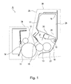
- Figure 1 is a principal sectional view of a process cartridge in an embodiment of the present invention.
- Figure 2 is a principal sectional view of an image forming apparatus in the embodiment of the present invention.
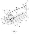
- Figure 3 is a perspective view of a developer accommodating container in the embodiment of the present invention.
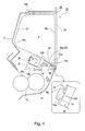
- Figure 4 is a sectional view of a developer accommodating unit in the embodiment of the present invention.
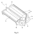
- Figure 5 is a perspective view of an outer appearance of the developer accommodating unit in the embodiment of the present invention.
- Parts (a) and (b) of Figure 6 are perspective sectional views of the developer accommodating unit in the embodiment of the present invention, wherein (a) shows a driving side and (b) shows a non-driving side.
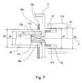
- Figure 7 is a sectional view of the developer accommodating unit at one longitudinal end portion (driving side).
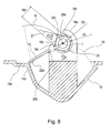
- Figure 8 is a sectional view of the neighborhood of a temporary shaft supporting portion in the embodiment of the present invention.
- Figure 9 is a perspective view for illustrating an assembling method of the developer accommodating unit in the embodiment of the present invention.
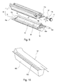
- Figure 10 is a perspective view for illustrating a conventional developer accommodating container.
- a developer accommodating container refers to at least a flexibility container and a sealing member for sealing an opening, provided to the sealing member, for permitting discharge of a developer.
- a developer accommodating unit includes at least the developer accommodating container and a frame for accommodating the developer accommodating container.
- Figure 1 is a principal sectional view of a process cartridge including the developer accommodating unit to which the present invention is applicable
- Figure 2 is a principal sectional view of an electrophotographic image forming apparatus to which the present invention is applicable.
- the process cartridge includes an image bearing member, which is an electrophotographic photosensitive member, and process means acting on the image bearing member and is detachably mountable to the image forming apparatus.
- the process means include a charging means for electrically charging a surface of the image bearing member, a developing device for forming an image on the image bearing member, and a cleaning means for removing a developer (toner, carrier, etc.) remaining on the image bearing member surface.
- the process cartridge A in this embodiment includes, as shown in Figure 1 , includes a photosensitive drum 11 as the image bearing member and includes, at a periphery of the photosensitive drum 11, a charging roller 12 as the charging means and a cleaner unit 24 including an elastic cleaning blade 14 as the cleaning means. Further, the process cartridge A includes a developer accommodating unit 25 including a first frame 17 and a second frame 18. The process cartridge A is prepared by integrally assembling the cleaner unit 24 and the developer accommodating unit 25, and is constituted so as to be detachably mountable to an image forming apparatus main assembly B as shown in Figure 2 .
- a developing device 38 includes a developing roller 13 as the developing means, a developing blade 15, a developer supplying roller 23, and a developer accommodating container 26 in which the developer is accommodated. The developing roller 13 and the developing blade 15 are supported by the first frame 17.
- the process cartridge A is, as shown in Figure 2 , mounted in the image forming apparatus main assembly B and is used for image formation.
- a sheet S is fed by a feeding roller 7 from a sheet cassette 6 mounted at a lower portion of the apparatus and in synchronism with this sheet feeding, the photosensitive drum 11 is selectively exposed to light by an exposure device 8 to form a latent image.
- the developer is supplied to the developing roller 13 (developer carrying member) by the developer supplying roller 23 having a sponge shape and is carried in a thin layer on the surface of the developing roller 13 by the developing blade 15.
- the developing roller 13 By applying a developing bias to the developing roller 13, the developer is supplied depending on the latent image and thus the latent image is developed into a developer image.
- This developer image is transferred onto the fed sheet S under bias voltage application to a transfer roller 9.
- the sheet S is conveyed to a fixing device 10, in which the image is fixed on the sheet S and then the sheet S is discharged to a discharge portion 3 at an upper portion of the apparatus.
- the developer accommodating unit 25 accommodated the developer to be supplied to the developing roller 13 depending on the image formation.
- the developer accommodating unit 25 in this embodiment includes the developer accommodating container 26 having flexibility in the frame.
- the developer accommodating unit 25 accommodates the developer in a developer bag 16, and a discharging portion 35 is sealed with a sealing member 19. Then, when used, the sealing member 19 is unsealed by an unsealing member 20, so that the developer is supplied to the developing roller 13.
- Figure3 is a perspective view of the developer accommodating container 26, as seen from a cross-sectional side, in a state in which the sealing member 20 is attached to the developer accommodating container 26, and
- Figure 4 is a sectional vie of the developer accommodating unit 25.
- the sectional view is illustrated along a plane passing through the unsealing member 20, an opening 35a and a portion-to-be-fixed 16d. Further, the sectional view is illustrated along a plane perpendicular to a rotation shaft of the unsealing member 20.
- the developer accommodating container 26 is constituted by a developer T, the developer bag 16 and the sealing member 19.
- the developer T is powder.
- the developer bag 16 of the developer accommodating container 26 is sealed with the sealing member 19 at the plurality of s 35a for permitting the discharge of the developer and includes an unshown filling opening for permitting the filling of the developer T.
- the filling opening is connected (joined) after the developer T is filled.
- the respective openings 35a and the filling opening of the developer accommodating container 26 in which the developer is applied is sealed and therefore the accommodated developer is not leaked out to the outside, so that the developer accommodating container 26 can be treated at a single unit.
- the sealing member 19 includes a portion-to-be-engaged 19b to be engaged with the unsealing member 20, thus being engageable with the unsealing member 20.
- the developer bag 16 accommodated the developer therein and has a bag-like shape which is deformable, and is provided with the plurality of openings 35a at the discharging portion 35 for permitting the discharge of the accommodated developer.
- the developer bag 16 includes developer bag fixing portions (portions-to-be-fixed) 16d and 16e to be fixed to the first frame 17 and the second frame 18.
- the developer bag 16 in this embodiment is constituted by bonding a sheet 16u which includes the discharging portion 35 and does not have air permeability (hereinafter, this sheet is referred to as a non-permeable sheet) and a sheet 16s which has the air permeability without causing the leakage of the developer (hereinafter, this sheet is referred to as a permeable sheet) to each other.
- a nonwoven fabric or the like formed of polyethylene telephthalate (PET), polyethylene (PE), polypropylene (PP) or the like in a thickness of 0.03 - 0.15 mm may preferably be used. Further, even when the material for the permeable sheet 16s is not the nonwoven fabric, a material having minute holes which is smaller in diameter than the powder such as the developer may also be used.
- a material for the developer bag 16 other than the permeable sheet 16s As a material for the developer bag 16 other than the permeable sheet 16s, a material having flexibility so as to improve efficiency during the discharge of the developer may preferably be used. Further, the material for the permeable sheet 16s may also have flexibility.
- the reason why the air permeability is imparted to the developer bag 16 as described above is that the developer bag 16 can meet states during manufacturing, during transportation until a user uses the cartridge A, and during storage. That is, the reason for the state during the manufacturing is that the developer bag 16 is made deformable and reducible in order to facilitate assembling the developer bag 16 with the frames 17 and 18. Further, the reason for the states during the transportation and during the storage is that the developer bag 16 can meet a change (difference) in air pressure between the inside and outside of the developer bag 16 during the transportation and during the storage of the process cartridge A.
- the difference in air pressure between the inside and outside of the developer bag 16 is generated in the case where the developer bag 16 is in a lower air-pressure environment during the transportation or the like than during the manufacturing or in the case where the developer bag 16 is stored at a higher temperature than during the manufacturing. For that reason, by expansion of the developer bag 16, there is a possibility that parts contacting the developer bag 16 are deformed or broken. Therefore, there is a need to control the air pressure and the temperature during the transportation and during the storage, so that facilitates for that purpose are required and a cost is increased. However, problems caused due to the difference in air pressure between the inside and outside of the developer bag 16 can be solved by partly imparting the air permeability to the developer bag 16.
- the developer bag 16 include the developer discharge portion 35 consisting of the plurality of openings 35a for permitting the discharge of the developer therein and the connecting portion 35b for connecting the plurality of openings 35a. Further, the discharge portion 35 is continuously surrounded by a welded bonding portion 22 to be unsealably bonded, so that the developer accommodated in the developer bag 16 is sealed with the sealing member 19.
- the bonding portion 22 has a rectangular shape consisting of two lines extending in a long direction (direction FR) and two lines extending in a short direction (direction E) so as to surround the discharge portion 35 and therefore the bonding portion 22 enables the sealing of the discharge portion 35.
- a bonding portion which is first unsealed is referred to as a first bonding portion 22a and a bonding portion which is unsealed later is referred to as a second bonding portion 22b.
- a bonding portion closer to a fold-back portion 19d is the first bonding portion 22a.
- a bonding portion opposing the first bonding portion 22a via the opening 35a is the second bonding portion 22b.
- an unsealing direction is a direction E in Figure 4 .
- the unsealing is effected by moving the sealing member 19 in a direction D, of the first bonding portion 22a and the second bonding portion 22b opposing to each other via the opening 35a, the first bonding portion 22a is first unsealed (peeled).
- a direction directed from the first bonding portion 22a to be first unsealed toward the second bonding portion 22b is the unsealing direction E.
- the plurality of openings 35a and the plurality of connecting portions 35b are alternately disposed along the direction FR perpendicular to the unsealing direction E. Further, the sealing member 19 is configured to be wound up by rotating the unsealing member 20 but the direction FR is the same direction as an axis (axial line) of the rotation shaft of the unsealing member 20.
- the openings 35a By disposing the openings 35a as described above, the developer is easily supplied, during the discharge thereof, to the developing roller 13 over the entire longitudinal direction without being localized. Further, the discharge portion 35 where the plurality of openings 35a are disposed is long in the developing roller FR and short in the direction E and therefore a distance required for the unsealing is shorter than that when the sealing member 19 is unsealed in the long direction FR, so that a time required for the unsealing can be shortened.
- the openings 35a are disposed so as to open downward with respect to the direction of gravitation in order to easily discharge the accommodated developer in the attitude during image formation.
- the above-described developer bag 16 is, as shown in Figures 3 and 4 , fixed inside the first frame 17 and the second frame 18 by two fixing portions 16d and 16e.
- the sealing member 19 covers the opening 35 of the developer bag 16 before use of the contact A to confine the developer in the developer bag 16.
- the sealing member 19 is wound up by the unsealing member 20, so that the openings 35a are exposed.
- the sealing member 19 is constituted by a sheet-like member including a sealing portion 19a for covering (sealing) the discharge portion 35 of the developer bag 16, a portion-to-be-engaged 19b to be fixed (engaged) with the unsealing member 20, and a sealing member connecting portion 19c which connects the sealing portion 19a and the portion-to-be-engaged 19b.
- the sheet member is formed of a laminate material having a sealant layer which exhibits an easy-unsealing property, and a base material therefor is polyethylene telephthalate (PET), polyethylene, polypropylene or the like.
- PET polyethylene telephthalate
- a thickness of the sheet member may appropriately be set in a range of 0.03 - 0.15 mm.
- the sealing portion 19a refers to a region where the sealing member 19 seals the plurality of openings 35a and connecting portions 35b of the developer bag 16. By the sealing portion 19a, the developer is prevented from being leaked from the inside of the developer bag 16 until before use of the process cartridge A.
- the sealing member 19 has a free end portion in one end side thereof with respect to the unsealing direction E and at the free end portion, the portion-to-be-engaged 19b to be engaged with the unsealing member 20 for winding up the sealing member 19 is provided.
- the sealing member connecting portion 19c is a portion for transmitting a force so as to pull off the bonding portion 22 by receiving the force from the unsealing member 20.
- fixing between the sealing member 19 and the unsealing member 20 is, in this embodiment, made by ultrasonic caulking similarly as in the case of the first fixing portion 16d.
- the fixing may also be made by welding, ultrasonic welding, bonding, insertion between the frames, hooking by a hole and a projection, or the like similarly as a means for fixing the first fixing portion 16d and the second fixing portion 16e.
- the unsealing member 20 pulls off the sealing member 19 from the developer bag 16 by applying a force to the sealing member 19 to move the sealing member 19.
- the unsealing member 20 has a rectangular shaft shape, and its length is slightly shorter than a distance from one longitudinal inner wall of a developing (device) frame 44 to another longitudinal inner wall of the developing frame 44. Both ends of the unsealing member 20 are rotatably supported by the second frame 18. On one surface of the rectangular shaft of the unsealing member 20, the portion-to-be-engaged 19c of the sealing member 19 is engaged and fixed. Then, the unsealing member 20 is rotated to wind up the sealing member 19, thus pulling off the sealing member 19 from the developer bag 16.
- Figure 5 is a perspective view of an outer appearance of the developer accommodating unit 25
- (a) of Figure 6 is a perspective sectional view of the developer accommodating unit 25 at one longitudinal end portion (driving side)
- (b) of Figure 6 is a perspective sectional view of the developer accommodating unit 25 at another longitudinal end portion (non-driving side).
- the developer accommodating unit 25 accommodates, as shown in Figure 5 , the developer accommodating container 26 in the single developing frame 44 constituted by integrally connecting the first frame 17, which supports the developing roller 13 and the developing blade 15, with the second frame 18.
- the developing roller 13 is rotatably supported by the first frame 17 at its longitudinal ends.
- a developing gear 42 is mounted integrally to the developing roller 13 at a longitudinal end portion of the developing roller 13.
- an input gear 43 engageable with an unshown driving force applying portion provided in the apparatus main assembly B is rotatably supported by the first frame 17 at a longitudinal end portion of the first frame 17.
- the input gear 43 is provided at a position where it is engaged with the developing gear 42.
- a driving shaft 41 which is a drive transmission member for transmitting a driving force for unsealing the developer accommodating container 26 is provided.
- the driving shaft 41 is, as shown in (a) of Figure 6 , rotatably and positionally supported, at its portion-to-be-supported 41d, by a driving shaft supporting portion 17a provided at one longitudinal end portion of the first frame 17.
- the driving shaft 41 is provided with a gear portion 41a. Further, as shown in Figure 5 , a stepped gear 46 is rotatably mounted to the first frame 17, and with the stepped gear 46, the gear portion 41a of the driving shaft 41 and the input gear 43 are engaged. As a result, the driving force of the input gear 43 is transmitted to the driving shaft 41 via the stepped gear 46.
- the longitudinal end portion (side) where the driving shaft 41 is provided is referred to as the driving side and its opposite side is referred to as the non-driving side.
- a D-cut hole-like portion-to-be-engaged 20a for being engaged with the driving shaft 41 is formed.
- the driving shaft 41 is provided with a projection-shaped engaging portion 41b having a D-cut cross-sectional shape which is the same as the shape of the portion-to-be-engaged 20a.
- the engaging portion 41b is engaged with the portion-to-be-engaged 20a, so that the driving shaft 41 is locked integrally with the unsealing member 20 and thus the driving shaft 41 and the unsealing member 20 are integrally rotatable.
- the driving shaft 41 is rotatably and positionally supported, at its portion-to-be-supported 41d, by the driving shaft supporting portion 17a of the first frame 17, so that the unsealing member 20 is positioned at a predetermined position of the first frame 17.
- a shaft sealing member 47 ( Figure 7 ) having elasticity is provided, so that leakage of the developer from the engaging portion of the driving shaft 41 is prevented.
- a shaft end portion 20b of the unsealing member 20 in the non-driving side is, as shown in (b) of Figure 6 , rotatably supported by being interposed between a shaft end supporting portion 17b of the first frame 17 and a shaft end supporting portion 18c of the second frame 18.
- the shaft end supporting portion 18c of the second frame 18 has an arcuate cut-away shape which is slightly larger than an outer diameter of the shaft end portion 20b, and an arcuate open portion 18f is formed in a shape which is slightly narrower than the outer diameter of the shaft end portion 20b.
- the shaft end supporting portion 17c of the first frame 17 has an arcuate U-character groove shape which is slightly larger than the outer diameter of the shaft end portion 20b, and its arcuate portion is formed so as to overlap with the arcuate open portion 18f of the shaft end supporting portion 18c of the second frame 18 as seen from an axial direction of the unsealing member 20.
- the portion-to-be-fixed 16d of the developer bag 16 is fixed to the fixing portion 18a of the second frame 18 and therefore a force is exerted on the first bonding portion 22a in the arrow direction, so that the first bonding portion 22a is peeled first.
- the welded portion at longitudinal end portions is peeled and thus the unsealing is advanced in the arrow E direction, so that the openings 35a are exposed and the second bonding portion 22b is finally peeled to complete the unsealing.
- an urging member 21 for urging the developer bag 16 is provided downstream of the portion-to-be-engaged 19b of the sealing member 19 with respect to the rotational direction C.
- the urging member 21 is a flexibility sheet extending in the longitudinal direction in a length which is slightly shorter than the distance between the both of the inner walls of the developing frame 44.
- the developer accommodating container 26 is assembled with the second frame 18 with respect to a radial direction of rotation of the unsealing member 20 (direction directed from a front side to a rear side in (a) of Figure 6 ), and then the portion-to-be-fixed 16d is mounted to the fixing portion 18a of the second frame 18.
- the unsealing member 20 is mounted to the second frame 18.
- the unsealing member is mounted by being temporarily supported by a temporary shaft supporting portion 18e which is a supporting member provided to the second frame 18.
- Figure 7 is a sectional view of the developer accommodating container 26 at one longitudinal end portion (driving side)
- Figure 8 is a sectional view of the neighborhood of the temporary shaft supporting portion 18e
- Figure 9 is a perspective view showing a step of incorporating the developer accommodating container 26 into the developing frame 44.
- a driving-side shaft end portion 20c of the unsealing member 20 has a circular shape in cross section.
- the temporary shaft supporting portion 18e having an inner diameter D2 which is slightly larger than an outer diameter d2 of the shaft end portion 20c of the unsealing member 20 is provided coaxially with a rotation center axis L of the unsealing member 20.
- the temporary shaft supporting portion 18e is provided with an open portion 18d having a width which is slightly smaller than the outer diameter d2 of the shaft end portion 20c of the unsealing member 20.
- the direction of the open portion 18d is such that the open portion 18d is open along a circumference R with the fold-back portion 19d of the sealing member 19 as a center axis (the first bonding portion 22a since the bonding portion 22 is folded back substantially at the first bonding portion 22a in this embodiment).
- the unsealing member 20 is engaged with the temporary shaft supporting portion 18e through the open portion 18d.
- the sealing member 19 is erroneously peeled from the first bonding portion 22a.
- the open portion 18d is configured to be directed in the above-described direction and thus the unsealing member 20 can be engaged with the temporary shaft supporting portion 18e along the circumference R, so that the allowance of the length of the sealing member 19 can be minimized.
- the open portion 18d is configured to have a width which is slightly smaller than the outer diameter d2 of the shaft end portion 20c of the unsealing member 20.
- the temporary shaft supporting portion 18e is provided with a preventing portion 18h for preventing the assembled unsealing member 20 from dropping from the temporary shaft supporting portion 18e.
- the open portion 18d is configured to be elastically deformed by a pressing force when the unsealing member 20 is assembled but not to be elastically deformed by a force to the extent of a repelling force, described below, when the unsealing member 20 is contacted to the developer bag 16.
- the unsealing member 20 when the unsealing member 20 is assembled with the temporary shaft supporting portion 18e, the unsealing member 20 is contacted to the developer bag 16 and therefore the unsealing member 20 receives, by the flexibility developer bag 16, a force for pushing back the unsealing member 20 in a direction indicated by an arrow P in Figure 8 . Further, the sealing member 19 is assembled in a state in which it is folded from the first bonding portion 22a and therefore a force for restoring the sealing member 19 to an original elongated shape. As a result, the unsealing member 20 receives a force in a direction indicated by an arrow Q in Figure 8 by the above-described restoring force of the sealing member 19.
- the open portion 18d is configured to be narrower than the outer diameter of the shaft end portion 20c, so that the preventing portion 18h for preventing the unsealing member 20 from dropping from the supporting member is formed. For this reason, when the shaft end portion 20c of the unsealing member 20 is once completely engaged with the temporary shaft supporting portion 18e, even under application of the above-described forces in the arrow P and Q directions, the unsealing member is prevented from dropping due to disengagement.
- the first frame 17 is welded with the second frame 18, thus being integrally assembled as the developing frame 44.
- the developing frame 44 accommodates therein the developer accommodating container 26 and the unsealing member 20.
- the driving shaft 41 is inserted together with the shaft sealing member 47 from the longitudinal direction (arrow V direction in Figure 9 ) toward the driving shaft supporting portion 17a.
- the portion-to-be-engaged 20a of the unsealing member 20 is, by the constitution of the temporary shaft supporting portion 18e, in stand-by inside the developing frame 44 in a range of gap between the outer diameter d2 of the unsealing member 20 and the inner diameter D2 of the temporary shaft supporting portion 18e as shown in Figure 8 .
- an end portion of the driving shaft 41 (engagement start-side end portion) has a tapered surface 41c as shown in Figure 7 . Further, also an end portion of the portion-to-be-engaged 20a of the unsealing member 20 (engagement start-side end portion) has a tapered surface 20e.
- a size (radial length of the tapered surface) t1 of the tapered surface 41c of the driving shaft 41 and a size T1 of the tapered surface 20e of the portion-to-be-engaged 20a are set so that the sum the sizes of both of the tapered surfaces is larger than an engagement gap between the outer diameter d2 of the unsealing member 20 and the inner diameter D2 of the temporary shaft supporting portion 18e, i.e., 2 x (T1+t1) > (D2-d2).
- the respective diameters are set so that a difference (D2-d2) between the outer diameter d2 of the shaft end portion of the unsealing member 20 and the inner diameter D2 of the temporary shaft supporting portion 18e is larger than a difference (D1-d1) between an outer diameter d1 of the portion-to-be-supported 41d of the driving shaft 41 and an inner diameter D1 of the driving shaft supporting portion 17a.
- the diameters are constituted so that the gap between the unsealing member 20 and the temporary shaft supporting portion 18e is larger than the engagement gap between the portion-to-be-supported 41c of the driving shaft 41 and the driving shaft supporting portion 17a, i.e., (D1-d1) > (D2-d2).
- the driving shaft 41 when the driving shaft 41 is rotatably assembled with the first frame 17, the shaft end portion 20c of the unsealing member 20 is spaced from the temporary shaft supporting portion 18e. Further, the driving shaft 41 integrated with the unsealing member 20 is positioned by the engagement between the portion-to-be-supported 41c of the driving shaft 41 and the driving shaft supporting portion 17a.
- the assembling of the unsealing member 20 becomes easy. Further, it is possible to prevent that the unsealing member 20 is moved inside the developing frame 44 due to impact or the like during assembling or transportation before the driving shaft 41 is incorporated into the unsealing member 20 and thus the engagement of the unsealing member 20 with the driving shaft 41 cannot be effected.
- a developer accommodating unit includes a flexible developer accommodating container sealed with a sealing member at its developer discharging opening; a rotatable unsealing member for removing the sealing member from the opening; a drive transmission member for transmitting a rotational force to the unsealing member, wherein the drive transmission member is mounted at one longitudinal end portion of the unsealing member and is rotatably assembled with a frame; and a supporting member for supporting the unsealing member when the unsealing member is assembled.
- the supporting member includes a preventing portion for preventing the unsealing member from dropping from the supporting member.
- a gap between the unsealing member and the supporting member is larger than a gap between the drive transmission member and the frame.
- the unsealing member is spaced from the supporting member.
Landscapes
- Physics & Mathematics (AREA)
- General Physics & Mathematics (AREA)
- Dry Development In Electrophotography (AREA)
Abstract
Description
- The present invention relates to a developer accommodating unit, a process cartridge using the developer accommodating unit and an image forming apparatus using the process cartridge.
- The image forming apparatus forms an image on a recording material (medium) by using, e.g., an electrophotographic image forming process and may include, e.g., an electrophotographic copying machine, an electrophotographic printer (such as an LED printer or a laser beam printer), an electrophotographic facsimile machine and the like.
- Further, the process cartridge is prepared by integrally assembling a photosensitive member and process means, such as a developing means, acting on the photosensitive member into a cartridge, which is detachably mountable to a main assembly of the electrophotographic image forming apparatus.
- Further, the developer accommodating unit at least includes a flexibility container for accommodating a developer.
- In a conventional electrophotographic image forming apparatus using the electrophotographic image forming process, a process cartridge type in which an electrophotographic photosensitive member and process means acting on the photosensitive member are integrally assembled into a cartridge and this cartridge is detachably mountable to a main assembly of the electrophotographic image forming apparatus is employed.
- In such a process cartridge, as shown in
Figure 10 , an opening provided to adeveloper accommodating container 100 for accommodating a developer (toner, carrier, etc.) is sealed with a sealingmember 101 constituted by a seal member or the like. A type in which abonding portion 102 of the sealingmember 101 is pulled off when used and thus the opening is unsealed (opened) to permit feeding of the developer has been widely used (Japanese Laid-Open Patent Application (JP-A)Hei 4-66980 - Further, a process cartridge in which the
developer accommodating container 100 is made deformable in order to solve a problem that the developer is scattered in the process cartridge in a developer filling step during manufacturing of the process cartridge has been devised (JP-A Hei 4-66980 - For the above-described developer accommodating container, it would be considered that the sealing
member 101 is automatically wound up in the image forming apparatus to permit unsealing. However, for that purpose, there is a need to incorporate, into the image forming apparatus, a mechanism for winding up the sealing member, but in recent years, downsizing of the cartridge is desired and therefore it is not easy to incorporate a driving shaft or the like with high accuracy. - The present invention has been accomplished in view of the above-described circumstances. A principal object of the present invention is, when a mechanism for winding up and unsealing a sealing member for a developer accommodating container is incorporated, to facilitate assembling of associated members and to enable the assembling with high accuracy.
- According to an aspect of the present invention, there is provided a developer accommodating unit for accommodating a developer, comprising: a flexible developer accommodating container which accommodates the developer and is sealed with a sealing member at its opening for permitting discharge of the developer; a rotatable unsealing member for removing the sealing member from the opening; a drive transmission member for transmitting a rotational force to the unsealing member, wherein the drive transmission member is mounted at one of longitudinal end portions of the unsealing member and is rotatably assembled with a frame; and a supporting member for supporting the unsealing member when the unsealing member is assembled, wherein the supporting member includes a preventing portion for preventing the unsealing member from dropping from the supporting member in a state before the drive transmission member is assembled with the frame, and wherein in a state in which the drive transmission member is assembled with the frame, a gap between the unsealing member and the supporting member is larger than a gap between the drive transmission member and the frame, and the unsealing member is spaced from the supporting member.
- These and other objects, features and advantages of the present invention will become more apparent upon a consideration of the following description of the preferred embodiments of the present invention taken in conjunction with the accompanying drawings.
-
Figure 1 is a principal sectional view of a process cartridge in an embodiment of the present invention. -
Figure 2 is a principal sectional view of an image forming apparatus in the embodiment of the present invention. -
Figure 3 is a perspective view of a developer accommodating container in the embodiment of the present invention. -
Figure 4 is a sectional view of a developer accommodating unit in the embodiment of the present invention. -
Figure 5 is a perspective view of an outer appearance of the developer accommodating unit in the embodiment of the present invention. - Parts (a) and (b) of
Figure 6 are perspective sectional views of the developer accommodating unit in the embodiment of the present invention, wherein (a) shows a driving side and (b) shows a non-driving side. -
Figure 7 is a sectional view of the developer accommodating unit at one longitudinal end portion (driving side). -
Figure 8 is a sectional view of the neighborhood of a temporary shaft supporting portion in the embodiment of the present invention. -
Figure 9 is a perspective view for illustrating an assembling method of the developer accommodating unit in the embodiment of the present invention. -
Figure 10 is a perspective view for illustrating a conventional developer accommodating container. - In the following description, a developer accommodating container refers to at least a flexibility container and a sealing member for sealing an opening, provided to the sealing member, for permitting discharge of a developer. A developer accommodating unit includes at least the developer accommodating container and a frame for accommodating the developer accommodating container.
-
Figure 1 is a principal sectional view of a process cartridge including the developer accommodating unit to which the present invention is applicable, andFigure 2 is a principal sectional view of an electrophotographic image forming apparatus to which the present invention is applicable. - The process cartridge includes an image bearing member, which is an electrophotographic photosensitive member, and process means acting on the image bearing member and is detachably mountable to the image forming apparatus. Examples of the process means include a charging means for electrically charging a surface of the image bearing member, a developing device for forming an image on the image bearing member, and a cleaning means for removing a developer (toner, carrier, etc.) remaining on the image bearing member surface.
- The process cartridge A in this embodiment includes, as shown in
Figure 1 , includes aphotosensitive drum 11 as the image bearing member and includes, at a periphery of thephotosensitive drum 11, acharging roller 12 as the charging means and acleaner unit 24 including anelastic cleaning blade 14 as the cleaning means. Further, the process cartridge A includes adeveloper accommodating unit 25 including afirst frame 17 and asecond frame 18. The process cartridge A is prepared by integrally assembling thecleaner unit 24 and thedeveloper accommodating unit 25, and is constituted so as to be detachably mountable to an image forming apparatus main assembly B as shown inFigure 2 . A developingdevice 38 includes a developingroller 13 as the developing means, a developingblade 15, adeveloper supplying roller 23, and adeveloper accommodating container 26 in which the developer is accommodated. The developingroller 13 and the developingblade 15 are supported by thefirst frame 17. - The process cartridge A is, as shown in
Figure 2 , mounted in the image forming apparatus main assembly B and is used for image formation. In the image formation, a sheet S is fed by afeeding roller 7 from asheet cassette 6 mounted at a lower portion of the apparatus and in synchronism with this sheet feeding, thephotosensitive drum 11 is selectively exposed to light by anexposure device 8 to form a latent image. The developer is supplied to the developing roller 13 (developer carrying member) by thedeveloper supplying roller 23 having a sponge shape and is carried in a thin layer on the surface of the developingroller 13 by the developingblade 15. By applying a developing bias to the developingroller 13, the developer is supplied depending on the latent image and thus the latent image is developed into a developer image. This developer image is transferred onto the fed sheet S under bias voltage application to atransfer roller 9. The sheet S is conveyed to afixing device 10, in which the image is fixed on the sheet S and then the sheet S is discharged to adischarge portion 3 at an upper portion of the apparatus. - The
developer accommodating unit 25 accommodated the developer to be supplied to the developingroller 13 depending on the image formation. Thedeveloper accommodating unit 25 in this embodiment includes thedeveloper accommodating container 26 having flexibility in the frame. Thedeveloper accommodating unit 25 accommodates the developer in adeveloper bag 16, and adischarging portion 35 is sealed with a sealingmember 19. Then, when used, the sealingmember 19 is unsealed by anunsealing member 20, so that the developer is supplied to the developingroller 13. - Next, a structure of the
developer accommodating container 26 will be described with reference toFigures 3 and4 .Figure3 is a perspective view of thedeveloper accommodating container 26, as seen from a cross-sectional side, in a state in which the sealingmember 20 is attached to thedeveloper accommodating container 26, andFigure 4 is a sectional vie of thedeveloper accommodating unit 25. The sectional view is illustrated along a plane passing through theunsealing member 20, an opening 35a and a portion-to-be-fixed 16d. Further, the sectional view is illustrated along a plane perpendicular to a rotation shaft of theunsealing member 20. - As shown in
Figure 3 , thedeveloper accommodating container 26 is constituted by a developer T, thedeveloper bag 16 and the sealingmember 19. The developer T is powder. - The
developer bag 16 of thedeveloper accommodating container 26 is sealed with the sealingmember 19 at the plurality ofs 35a for permitting the discharge of the developer and includes an unshown filling opening for permitting the filling of the developer T. The filling opening is connected (joined) after the developer T is filled. Thus, therespective openings 35a and the filling opening of thedeveloper accommodating container 26 in which the developer is applied is sealed and therefore the accommodated developer is not leaked out to the outside, so that thedeveloper accommodating container 26 can be treated at a single unit. Further, as shown inFigure 3 , the sealingmember 19 includes a portion-to-be-engaged 19b to be engaged with theunsealing member 20, thus being engageable with theunsealing member 20. - As shown in
Figures 3 and4 , thedeveloper bag 16 accommodated the developer therein and has a bag-like shape which is deformable, and is provided with the plurality ofopenings 35a at thedischarging portion 35 for permitting the discharge of the accommodated developer. - Further, the
developer bag 16 includes developer bag fixing portions (portions-to-be-fixed) 16d and 16e to be fixed to thefirst frame 17 and thesecond frame 18. - The
developer bag 16 in this embodiment is constituted by bonding asheet 16u which includes the dischargingportion 35 and does not have air permeability (hereinafter, this sheet is referred to as a non-permeable sheet) and asheet 16s which has the air permeability without causing the leakage of the developer (hereinafter, this sheet is referred to as a permeable sheet) to each other. - As a material for the
permeable sheet 16s, a nonwoven fabric or the like formed of polyethylene telephthalate (PET), polyethylene (PE), polypropylene (PP) or the like in a thickness of 0.03 - 0.15 mm may preferably be used. Further, even when the material for thepermeable sheet 16s is not the nonwoven fabric, a material having minute holes which is smaller in diameter than the powder such as the developer may also be used. - As a material for the
developer bag 16 other than thepermeable sheet 16s, a material having flexibility so as to improve efficiency during the discharge of the developer may preferably be used. Further, the material for thepermeable sheet 16s may also have flexibility. - The reason why the air permeability is imparted to the
developer bag 16 as described above is that thedeveloper bag 16 can meet states during manufacturing, during transportation until a user uses the cartridge A, and during storage. That is, the reason for the state during the manufacturing is that thedeveloper bag 16 is made deformable and reducible in order to facilitate assembling thedeveloper bag 16 with theframes developer bag 16 can meet a change (difference) in air pressure between the inside and outside of thedeveloper bag 16 during the transportation and during the storage of the process cartridge A. The difference in air pressure between the inside and outside of thedeveloper bag 16 is generated in the case where thedeveloper bag 16 is in a lower air-pressure environment during the transportation or the like than during the manufacturing or in the case where thedeveloper bag 16 is stored at a higher temperature than during the manufacturing. For that reason, by expansion of thedeveloper bag 16, there is a possibility that parts contacting thedeveloper bag 16 are deformed or broken. Therefore, there is a need to control the air pressure and the temperature during the transportation and during the storage, so that facilitates for that purpose are required and a cost is increased. However, problems caused due to the difference in air pressure between the inside and outside of thedeveloper bag 16 can be solved by partly imparting the air permeability to thedeveloper bag 16. - As shown in
Figure 3 , thedeveloper bag 16 include thedeveloper discharge portion 35 consisting of the plurality ofopenings 35a for permitting the discharge of the developer therein and the connectingportion 35b for connecting the plurality ofopenings 35a. Further, thedischarge portion 35 is continuously surrounded by a weldedbonding portion 22 to be unsealably bonded, so that the developer accommodated in thedeveloper bag 16 is sealed with the sealingmember 19. - The
bonding portion 22 has a rectangular shape consisting of two lines extending in a long direction (direction FR) and two lines extending in a short direction (direction E) so as to surround thedischarge portion 35 and therefore thebonding portion 22 enables the sealing of thedischarge portion 35. - Here, of the two lines of the welded
bonding portion 22 extending in the long direction (direction FR), a bonding portion which is first unsealed is referred to as afirst bonding portion 22a and a bonding portion which is unsealed later is referred to as asecond bonding portion 22b. In this embodiment, as shown inFigure 4 , in the case where thebonding portion 22 is viewed along the surface of the sealingmember 19, a bonding portion closer to a fold-back portion 19d is thefirst bonding portion 22a. Further, a bonding portion opposing thefirst bonding portion 22a via theopening 35a is thesecond bonding portion 22b. - In this embodiment, an unsealing direction is a direction E in
Figure 4 . In the case where the unsealing is effected by moving the sealingmember 19 in a direction D, of thefirst bonding portion 22a and thesecond bonding portion 22b opposing to each other via theopening 35a, thefirst bonding portion 22a is first unsealed (peeled). Thus, a direction directed from thefirst bonding portion 22a to be first unsealed toward thesecond bonding portion 22b is the unsealing direction E. - The plurality of
openings 35a and the plurality of connectingportions 35b are alternately disposed along the direction FR perpendicular to the unsealing direction E. Further, the sealingmember 19 is configured to be wound up by rotating the unsealingmember 20 but the direction FR is the same direction as an axis (axial line) of the rotation shaft of the unsealingmember 20. - By disposing the
openings 35a as described above, the developer is easily supplied, during the discharge thereof, to the developingroller 13 over the entire longitudinal direction without being localized. Further, thedischarge portion 35 where the plurality ofopenings 35a are disposed is long in the developing roller FR and short in the direction E and therefore a distance required for the unsealing is shorter than that when the sealingmember 19 is unsealed in the long direction FR, so that a time required for the unsealing can be shortened. - Further, in an attitude during image formation, the
openings 35a are disposed so as to open downward with respect to the direction of gravitation in order to easily discharge the accommodated developer in the attitude during image formation. - The above-described
developer bag 16 is, as shown inFigures 3 and4 , fixed inside thefirst frame 17 and thesecond frame 18 by two fixingportions - As shown in
Figures 3 and4 , the sealingmember 19 covers theopening 35 of thedeveloper bag 16 before use of the contact A to confine the developer in thedeveloper bag 16. The sealingmember 19 is wound up by the unsealingmember 20, so that theopenings 35a are exposed. The sealingmember 19 is constituted by a sheet-like member including a sealingportion 19a for covering (sealing) thedischarge portion 35 of thedeveloper bag 16, a portion-to-be-engaged 19b to be fixed (engaged) with the unsealingmember 20, and a sealingmember connecting portion 19c which connects the sealingportion 19a and the portion-to-be-engaged 19b. The sheet member is formed of a laminate material having a sealant layer which exhibits an easy-unsealing property, and a base material therefor is polyethylene telephthalate (PET), polyethylene, polypropylene or the like. A thickness of the sheet member may appropriately be set in a range of 0.03 - 0.15 mm. - The sealing
portion 19a refers to a region where the sealingmember 19 seals the plurality ofopenings 35a and connectingportions 35b of thedeveloper bag 16. By the sealingportion 19a, the developer is prevented from being leaked from the inside of thedeveloper bag 16 until before use of the process cartridge A. The sealingmember 19 has a free end portion in one end side thereof with respect to the unsealing direction E and at the free end portion, the portion-to-be-engaged 19b to be engaged with the unsealingmember 20 for winding up the sealingmember 19 is provided. - Of the sealing
member 19, a portion for connecting thebonding portion 22 and the portion-to-be-engaged 19b is the sealingmember connecting portion 19c. The sealingmember connecting portion 19c is a portion for transmitting a force so as to pull off thebonding portion 22 by receiving the force from the unsealingmember 20. - Further, fixing between the sealing
member 19 and the unsealingmember 20 is, in this embodiment, made by ultrasonic caulking similarly as in the case of thefirst fixing portion 16d. Other than the ultrasonic caulking, the fixing may also be made by welding, ultrasonic welding, bonding, insertion between the frames, hooking by a hole and a projection, or the like similarly as a means for fixing thefirst fixing portion 16d and thesecond fixing portion 16e. - The unsealing
member 20 pulls off the sealingmember 19 from thedeveloper bag 16 by applying a force to the sealingmember 19 to move the sealingmember 19. The unsealingmember 20 has a rectangular shaft shape, and its length is slightly shorter than a distance from one longitudinal inner wall of a developing (device)frame 44 to another longitudinal inner wall of the developingframe 44. Both ends of the unsealingmember 20 are rotatably supported by thesecond frame 18. On one surface of the rectangular shaft of the unsealingmember 20, the portion-to-be-engaged 19c of the sealingmember 19 is engaged and fixed. Then, the unsealingmember 20 is rotated to wind up the sealingmember 19, thus pulling off the sealingmember 19 from thedeveloper bag 16. - Next, a drive transmission constitution of the
developer accommodating unit 25 will be described with reference toFigures 5 and6 .Figure 5 is a perspective view of an outer appearance of thedeveloper accommodating unit 25, (a) ofFigure 6 is a perspective sectional view of thedeveloper accommodating unit 25 at one longitudinal end portion (driving side), and (b) ofFigure 6 is a perspective sectional view of thedeveloper accommodating unit 25 at another longitudinal end portion (non-driving side). - The
developer accommodating unit 25 accommodates, as shown inFigure 5 , thedeveloper accommodating container 26 in the single developingframe 44 constituted by integrally connecting thefirst frame 17, which supports the developingroller 13 and the developingblade 15, with thesecond frame 18. - The developing
roller 13 is rotatably supported by thefirst frame 17 at its longitudinal ends. A developinggear 42 is mounted integrally to the developingroller 13 at a longitudinal end portion of the developingroller 13. Further, aninput gear 43 engageable with an unshown driving force applying portion provided in the apparatus main assembly B is rotatably supported by thefirst frame 17 at a longitudinal end portion of thefirst frame 17. Theinput gear 43 is provided at a position where it is engaged with the developinggear 42. Further, a drivingshaft 41 which is a drive transmission member for transmitting a driving force for unsealing thedeveloper accommodating container 26 is provided. The drivingshaft 41 is, as shown in (a) ofFigure 6 , rotatably and positionally supported, at its portion-to-be-supported 41d, by a drivingshaft supporting portion 17a provided at one longitudinal end portion of thefirst frame 17. - The driving
shaft 41 is provided with agear portion 41a. Further, as shown inFigure 5 , a steppedgear 46 is rotatably mounted to thefirst frame 17, and with the steppedgear 46, thegear portion 41a of the drivingshaft 41 and theinput gear 43 are engaged. As a result, the driving force of theinput gear 43 is transmitted to the drivingshaft 41 via the steppedgear 46. Incidentally, in the following description, the longitudinal end portion (side) where the drivingshaft 41 is provided is referred to as the driving side and its opposite side is referred to as the non-driving side. - In the driving-side longitudinal end portion of the unsealing
member 20, a D-cut hole-like portion-to-be-engaged 20a for being engaged with the drivingshaft 41 is formed. On the other hand, the drivingshaft 41 is provided with a projection-shapedengaging portion 41b having a D-cut cross-sectional shape which is the same as the shape of the portion-to-be-engaged 20a. The engagingportion 41b is engaged with the portion-to-be-engaged 20a, so that the drivingshaft 41 is locked integrally with the unsealingmember 20 and thus the drivingshaft 41 and the unsealingmember 20 are integrally rotatable. - Further, the driving
shaft 41 is rotatably and positionally supported, at its portion-to-be-supported 41d, by the drivingshaft supporting portion 17a of thefirst frame 17, so that the unsealingmember 20 is positioned at a predetermined position of thefirst frame 17. - Further, between the driving
shaft 41 and the drivingshaft supporting portion 17a for supporting the drivingshaft 41, a shaft sealing member 47 (Figure 7 ) having elasticity is provided, so that leakage of the developer from the engaging portion of the drivingshaft 41 is prevented. - On the other hand, a
shaft end portion 20b of the unsealingmember 20 in the non-driving side is, as shown in (b) ofFigure 6 , rotatably supported by being interposed between a shaftend supporting portion 17b of thefirst frame 17 and a shaftend supporting portion 18c of thesecond frame 18. The shaftend supporting portion 18c of thesecond frame 18 has an arcuate cut-away shape which is slightly larger than an outer diameter of theshaft end portion 20b, and an arcuateopen portion 18f is formed in a shape which is slightly narrower than the outer diameter of theshaft end portion 20b. On the other hand, the shaft end supporting portion 17c of thefirst frame 17 has an arcuate U-character groove shape which is slightly larger than the outer diameter of theshaft end portion 20b, and its arcuate portion is formed so as to overlap with the arcuateopen portion 18f of the shaftend supporting portion 18c of thesecond frame 18 as seen from an axial direction of the unsealingmember 20. - Next, the unsealing of the
developer accommodating container 26 will be described with reference toFigures 3 and4 . When the driving force is inputted from the apparatus main assembly B to theinput gear 43, the driving force is transmitted to the drivingshaft 41 via the steppedgear 46, so that the rotational force is transmitted to the unsealingmember 20 provided integrally with the drivingshaft 41 and thus the unsealingmember 20 is rotated in a direction indicated by an arrow C inFigure 4 . With this rotation, the unsealingmember 19 fixed on the sealingmember 19 is pulled in the arrow D direction. Here, the portion-to-be-fixed 16d of thedeveloper bag 16 is fixed to the fixingportion 18a of thesecond frame 18 and therefore a force is exerted on thefirst bonding portion 22a in the arrow direction, so that thefirst bonding portion 22a is peeled first. As the rotation of the unsealingmember 20 is advanced, the welded portion at longitudinal end portions is peeled and thus the unsealing is advanced in the arrow E direction, so that theopenings 35a are exposed and thesecond bonding portion 22b is finally peeled to complete the unsealing. - On the unsealing
member 20, an urgingmember 21 for urging thedeveloper bag 16 is provided downstream of the portion-to-be-engaged 19b of the sealingmember 19 with respect to the rotational direction C. The urgingmember 21 is a flexibility sheet extending in the longitudinal direction in a length which is slightly shorter than the distance between the both of the inner walls of the developingframe 44. When the unsealingmember 20 is rotated, the urgingmember 21 is rotated while externally urging thedeveloper bag 16. By this operation, the developer T in thedeveloper accommodating container 26 is pushed toward theopenings 35a and thus is discharged through theopenings 35a. Further, in this embodiment, the urgingmember 21 has the function of stirring the developer discharged from thedeveloper accommodating container 26 and also has the function of feeding, toward the developingroller 13, the developer discharged from thedeveloper accommodating container 26. - Next, a step of assembling the
developer accommodating container 26, to which the unsealingmember 20 is mounted, with the developingframe 44 will be described. First, the sealingmember 19 is bonded and then the developer T is filled in thedeveloper bag 16 where thedischarge portion 35 is sealed with the sealingmember 19, so that thedeveloper accommodating container 26 is prepared. Then, the unsealingmember 20 is engaged with the portion-to-be-engaged 19b of the sealingmember 19 to integrally assembling thedeveloper bag 16, the sealingmember 19 and the unsealingmember 20, thus preparing thedeveloper accommodating container 26 shown inFigure 3 . - The
developer accommodating container 26 is assembled with thesecond frame 18 with respect to a radial direction of rotation of the unsealing member 20 (direction directed from a front side to a rear side in (a) ofFigure 6 ), and then the portion-to-be-fixed 16d is mounted to the fixingportion 18a of thesecond frame 18. - After the
developer accommodating container 26 is assembled with thesecond frame 18, the unsealingmember 20 is mounted to thesecond frame 18. At this time, in this embodiment, the unsealing member is mounted by being temporarily supported by a temporaryshaft supporting portion 18e which is a supporting member provided to thesecond frame 18. - A structure of the temporary
shaft supporting portion 18e will be described with reference toFigures 7 ,8 and9 .Figure 7 is a sectional view of thedeveloper accommodating container 26 at one longitudinal end portion (driving side),Figure 8 is a sectional view of the neighborhood of the temporaryshaft supporting portion 18e, andFigure 9 is a perspective view showing a step of incorporating thedeveloper accommodating container 26 into the developingframe 44. - As shown in
Figure 8 , a driving-sideshaft end portion 20c of the unsealingmember 20 has a circular shape in cross section. On the other hand, at an inner driving-side end portion of thesecond frame 18, the temporaryshaft supporting portion 18e having an inner diameter D2 which is slightly larger than an outer diameter d2 of theshaft end portion 20c of the unsealingmember 20 is provided coaxially with a rotation center axis L of the unsealingmember 20. The temporaryshaft supporting portion 18e is provided with anopen portion 18d having a width which is slightly smaller than the outer diameter d2 of theshaft end portion 20c of the unsealingmember 20. The direction of theopen portion 18d is such that theopen portion 18d is open along a circumference R with the fold-back portion 19d of the sealingmember 19 as a center axis (thefirst bonding portion 22a since thebonding portion 22 is folded back substantially at thefirst bonding portion 22a in this embodiment). - After the portion-to-be-fixed 16d of the
developer bag 16 is mounted to the fixingportion 18a of thesecond frame 18, the unsealingmember 20 is engaged with the temporaryshaft supporting portion 18e through theopen portion 18d. At that time, when tension is exerted on the sealingmember 19, there is a possibility that the sealingmember 19 is erroneously peeled from thefirst bonding portion 22a. For that reason, there is a need to provide a length from thefirst bonding portion 22a of the sealingmember 19 to the portion-to-be-engaged 19b of the sealingmember 20 with an allowance to some extent. However, in this embodiment, theopen portion 18d is configured to be directed in the above-described direction and thus the unsealingmember 20 can be engaged with the temporaryshaft supporting portion 18e along the circumference R, so that the allowance of the length of the sealingmember 19 can be minimized. - Further, the
open portion 18d is configured to have a width which is slightly smaller than the outer diameter d2 of theshaft end portion 20c of the unsealingmember 20. As a result, the temporaryshaft supporting portion 18e is provided with a preventingportion 18h for preventing the assembled unsealingmember 20 from dropping from the temporaryshaft supporting portion 18e. When theshaft end portion 20c is engaged with the temporaryshaft supporting portion 18e, theopen portion 18d is elastically deformed until its width is equal to the outer diameter d2 of theshaft end portion 20e and then when theshaft end portion 20c is completely engaged, theopen portion 18d is elastically restored, so that the engagement is completed. - Incidentally, the
open portion 18d is configured to be elastically deformed by a pressing force when the unsealingmember 20 is assembled but not to be elastically deformed by a force to the extent of a repelling force, described below, when the unsealingmember 20 is contacted to thedeveloper bag 16. - In this embodiment, when the unsealing
member 20 is assembled with the temporaryshaft supporting portion 18e, the unsealingmember 20 is contacted to thedeveloper bag 16 and therefore the unsealingmember 20 receives, by theflexibility developer bag 16, a force for pushing back the unsealingmember 20 in a direction indicated by an arrow P inFigure 8 . Further, the sealingmember 19 is assembled in a state in which it is folded from thefirst bonding portion 22a and therefore a force for restoring the sealingmember 19 to an original elongated shape. As a result, the unsealingmember 20 receives a force in a direction indicated by an arrow Q inFigure 8 by the above-described restoring force of the sealingmember 19. - However, as described above, the
open portion 18d is configured to be narrower than the outer diameter of theshaft end portion 20c, so that the preventingportion 18h for preventing the unsealingmember 20 from dropping from the supporting member is formed. For this reason, when theshaft end portion 20c of the unsealingmember 20 is once completely engaged with the temporaryshaft supporting portion 18e, even under application of the above-described forces in the arrow P and Q directions, the unsealing member is prevented from dropping due to disengagement. - After the unsealing
member 20 is engaged with the temporaryshaft supporting portion 18e as described above, as shown inFigure 9 , thefirst frame 17 is welded with thesecond frame 18, thus being integrally assembled as the developingframe 44. In this way, the developingframe 44 accommodates therein thedeveloper accommodating container 26 and the unsealingmember 20. - Thereafter, the driving
shaft 41 is inserted together with theshaft sealing member 47 from the longitudinal direction (arrow V direction inFigure 9 ) toward the drivingshaft supporting portion 17a. At this time, the portion-to-be-engaged 20a of the unsealingmember 20 is, by the constitution of the temporaryshaft supporting portion 18e, in stand-by inside the developingframe 44 in a range of gap between the outer diameter d2 of the unsealingmember 20 and the inner diameter D2 of the temporaryshaft supporting portion 18e as shown inFigure 8 . - In this embodiment, an end portion of the driving shaft 41 (engagement start-side end portion) has a tapered
surface 41c as shown inFigure 7 . Further, also an end portion of the portion-to-be-engaged 20a of the unsealing member 20 (engagement start-side end portion) has a taperedsurface 20e. Here, a size (radial length of the tapered surface) t1 of the taperedsurface 41c of the drivingshaft 41 and a size T1 of the taperedsurface 20e of the portion-to-be-engaged 20a are set so that the sum the sizes of both of the tapered surfaces is larger than an engagement gap between the outer diameter d2 of the unsealingmember 20 and the inner diameter D2 of the temporaryshaft supporting portion 18e, i.e., 2 x (T1+t1) > (D2-d2). - By employing such a constitution, in a state in which an outer peripheral portion of the
shaft end portion 20c of the unsealingmember 20 is contacted to and supported by an inner peripheral portion of the temporaryshaft supporting portion 18e, when the engagingportion 41b of the drivingshaft 41 is gradually inserted into the portion-to-be-engaged 20a of the unsealingmember 20, the taperedsurface 41c of the drivingshaft 41 is guided by the taperedsurface 20e of the unsealingmember 20. For this reason, the engagingportion 41b of the drivingshaft 41 is inserted into and engaged with the portion-to-be-engaged 20a of the unsealingmember 20, and the same time, the portion-to-be-supported 41d of the drivingshaft 41 is engaged with the drivingshaft supporting portion 17a of thefirst frame 17. - Here, in this embodiment, as shown in
Figure 7 , the respective diameters are set so that a difference (D2-d2) between the outer diameter d2 of the shaft end portion of the unsealingmember 20 and the inner diameter D2 of the temporaryshaft supporting portion 18e is larger than a difference (D1-d1) between an outer diameter d1 of the portion-to-be-supported 41d of the drivingshaft 41 and an inner diameter D1 of the drivingshaft supporting portion 17a. That is, in a state in which the drivingshaft 41 is assembled with thefirst frame 17, the diameters are constituted so that the gap between the unsealingmember 20 and the temporaryshaft supporting portion 18e is larger than the engagement gap between the portion-to-be-supported 41c of the drivingshaft 41 and the drivingshaft supporting portion 17a, i.e., (D1-d1) > (D2-d2). - As a result, when the driving
shaft 41 is rotatably assembled with thefirst frame 17, theshaft end portion 20c of the unsealingmember 20 is spaced from the temporaryshaft supporting portion 18e. Further, the drivingshaft 41 integrated with the unsealingmember 20 is positioned by the engagement between the portion-to-be-supported 41c of the drivingshaft 41 and the drivingshaft supporting portion 17a. - By providing the temporary
shaft supporting portion 18e as described above and then by assembling the unsealingmember 20 within the frame by using the temporaryshaft supporting portion 18e, the assembling of the unsealingmember 20 becomes easy. Further, it is possible to prevent that the unsealingmember 20 is moved inside the developingframe 44 due to impact or the like during assembling or transportation before the drivingshaft 41 is incorporated into the unsealingmember 20 and thus the engagement of the unsealingmember 20 with the drivingshaft 41 cannot be effected. - While the invention has been described with reference to the structures disclosed herein, it is not confined to the details set forth and this application is intended to cover such modifications or changes as may come within the purpose of the improvements or the scope of the following claims.
A developer accommodating unit includes a flexible developer accommodating container sealed with a sealing member at its developer discharging opening; a rotatable unsealing member for removing the sealing member from the opening; a drive transmission member for transmitting a rotational force to the unsealing member, wherein the drive transmission member is mounted at one longitudinal end portion of the unsealing member and is rotatably assembled with a frame; and a supporting member for supporting the unsealing member when the unsealing member is assembled. The supporting member includes a preventing portion for preventing the unsealing member from dropping from the supporting member. In a state in which the drive transmission member is assembled with the frame, a gap between the unsealing member and the supporting member is larger than a gap between the drive transmission member and the frame. The unsealing member is spaced from the supporting member.
Claims (6)
- A developer accommodating unit for accommodating a developer, comprising:a flexible developer accommodating container which accommodates the developer and is sealed with a sealing member at its opening for permitting discharge of the developer;a rotatable unsealing member for removing the sealing member from the opening;a drive transmission member for transmitting a rotational force to said unsealing member, wherein said drive transmission member is mounted at one of longitudinal end portions of said unsealing member and is rotatably assembled with a frame; anda supporting member for supporting said unsealing member when said unsealing member is assembled,wherein said supporting member includes a preventing portion for preventing said unsealing member from dropping from said supporting member in a state before said drive transmission member is assembled with the frame, andwherein in a state in which said drive transmission member is assembled with the frame, a gap between said unsealing member and said supporting member is larger than a gap between said drive transmission member and the frame, and said unsealing member is spaced from said supporting member.
- A developer accommodating unit according to Claim 1, wherein said preventing portion prevents said unsealing member from dropping from said sealing member by a repelling force received by said unsealing member when said unsealing member contacts said developer accommodating container.
- A developer accommodating unit according to Claim 1 or 2, wherein said unsealing member includes an engaging portion at one of its longitudinal end portions and said drive transmission member includes a portion-to-be-engaged engageable with said engaging portion,
wherein each of engagement start end portions of said engaging portion and said portion-to-be-engaged is tapered, and
wherein a sum of the tapered engagement start end portions is set so as to be larger than the gap between said unsealing member and said sealing member. - A developer accommodating unit according to any one of Claims 1 - 3, wherein in a state in which said developer accommodating container and said unsealing member are assembled with the frame, said sealing member is folded back between said developer accommodating container and said unsealing member and said sealing member is provided with an open portion, for permitting assembling of said unsealing member, which is open upward along a circumference with a portion, as a center of the circumference, where the sealing member is folded back.
- A process cartridge detachably mountable to a main assembly of an image forming apparatus, comprising:a developer accommodating unit according to any one of Claims 1 - 4; andan electrophotographic photosensitive member integrally assembled with said developer accommodating unit.
- An electrophotographic image forming apparatus, comprising:a process cartridge according to Claim 5.
Applications Claiming Priority (1)
| Application Number | Priority Date | Filing Date | Title |
|---|---|---|---|
| JP2011260187A JP5911275B2 (en) | 2011-11-29 | 2011-11-29 | Developer storage unit, developing device, process cartridge, electrophotographic image forming apparatus |
Publications (3)
| Publication Number | Publication Date |
|---|---|
| EP2600206A2 true EP2600206A2 (en) | 2013-06-05 |
| EP2600206A3 EP2600206A3 (en) | 2014-07-02 |
| EP2600206B1 EP2600206B1 (en) | 2020-01-08 |
Family
ID=47143691
Family Applications (1)
| Application Number | Title | Priority Date | Filing Date |
|---|---|---|---|
| EP12191365.1A Active EP2600206B1 (en) | 2011-11-29 | 2012-11-06 | Developer accommodating unit, process cartridge and electrophotographic image forming apparatus |
Country Status (4)
| Country | Link |
|---|---|
| US (1) | US8867955B2 (en) |
| EP (1) | EP2600206B1 (en) |
| JP (1) | JP5911275B2 (en) |
| CN (1) | CN103135407B (en) |
Cited By (3)
| Publication number | Priority date | Publication date | Assignee | Title |
|---|---|---|---|---|
| CN105549358A (en) * | 2014-10-27 | 2016-05-04 | 佳能株式会社 | Remanufacturing method of developer accommodating unit |
| EP3026498A1 (en) * | 2014-10-27 | 2016-06-01 | Canon Kabushiki Kaisha | Remanufacturing method of developer accommodating unit |
| US9575434B2 (en) | 2014-10-27 | 2017-02-21 | Canon Kabushiki Kaisha | Remanufacturing method of developer accommodating unit |
Families Citing this family (38)
| Publication number | Priority date | Publication date | Assignee | Title |
|---|---|---|---|---|
| JP5420025B2 (en) | 2011-07-14 | 2014-02-19 | キヤノン株式会社 | Developer storage unit, process cartridge, electrophotographic image forming apparatus |
| EP2733543B1 (en) | 2011-07-14 | 2020-04-15 | Canon Kabushiki Kaisha | Developer storage container, process cartridge, and electrophotographic image forming device |
| JP5420026B2 (en) | 2011-07-14 | 2014-02-19 | キヤノン株式会社 | Developer storage container, developer storage unit, process cartridge, electrophotographic image forming apparatus |
| CN103688224B (en) | 2011-07-14 | 2017-10-31 | 佳能株式会社 | Developer-containing unit, handle box and electrophotographic image forming |
| US8867966B2 (en) * | 2011-12-30 | 2014-10-21 | Lexmark International, Inc. | Toner cartridge for use in an image forming device |
| JP6053404B2 (en) | 2012-06-15 | 2016-12-27 | キヤノン株式会社 | Developer storage unit, developing device, process cartridge, electrophotographic image forming apparatus |
| JP6157078B2 (en) | 2012-09-04 | 2017-07-05 | キヤノン株式会社 | Developing unit, process cartridge, and image forming apparatus |
| JP5693678B2 (en) | 2012-09-10 | 2015-04-01 | キヤノン株式会社 | Developer storage container, developer storage unit, process cartridge, image forming apparatus |
| JP6066841B2 (en) | 2012-09-10 | 2017-01-25 | キヤノン株式会社 | Developing cartridge, process cartridge, and image forming apparatus |
| JP6116162B2 (en) | 2012-09-10 | 2017-04-19 | キヤノン株式会社 | Developer storage unit, developing device, process cartridge, and image forming apparatus |
| JP5980061B2 (en) | 2012-09-11 | 2016-08-31 | キヤノン株式会社 | Developer container, process cartridge, and image forming apparatus |
| JP2014056025A (en) | 2012-09-11 | 2014-03-27 | Canon Inc | Developer storage container, process cartridge, and image forming apparatus |
| JP6120730B2 (en) | 2012-09-13 | 2017-04-26 | キヤノン株式会社 | Developer storage unit, process cartridge, image forming apparatus |
| JP6245932B2 (en) | 2012-11-06 | 2017-12-13 | キヤノン株式会社 | Cartridge, developing cartridge, process cartridge, and image forming apparatus |
| JP6202820B2 (en) | 2013-01-11 | 2017-09-27 | キヤノン株式会社 | Developer storage unit, developing device, process cartridge, and image forming apparatus |
| JP6116253B2 (en) | 2013-01-11 | 2017-04-19 | キヤノン株式会社 | Developer storage unit, developing device, process cartridge, and image forming apparatus including the same |
| JP6112971B2 (en) | 2013-01-11 | 2017-04-12 | キヤノン株式会社 | Developer container, developing device, process cartridge, electrophotographic image forming apparatus |
| JP6116254B2 (en) | 2013-01-11 | 2017-04-19 | キヤノン株式会社 | Developer storage unit, developing device, process cartridge, image forming apparatus |
| JP6282149B2 (en) | 2013-06-05 | 2018-02-21 | キヤノン株式会社 | Developer storage unit, developing device, process cartridge, and image forming apparatus |
| JP2015028594A (en) * | 2013-06-24 | 2015-02-12 | キヤノン株式会社 | Cartridge, process cartridge, and image forming apparatus |
| JP6173069B2 (en) | 2013-06-27 | 2017-08-02 | キヤノン株式会社 | Developer container, developer cartridge, process cartridge, and image forming apparatus |
| CN105143992B (en) * | 2014-01-23 | 2019-06-14 | 京瓷办公信息系统株式会社 | Developer accommodating container and image forming apparatus including the developer accommodating container |
| JP6381222B2 (en) * | 2014-02-18 | 2018-08-29 | キヤノン株式会社 | Developer storage unit and manufacturing method thereof, developing device, process cartridge, and image forming apparatus |
| JP6138181B2 (en) | 2014-04-15 | 2017-05-31 | キヤノン株式会社 | Resin molded product and cartridge used for image forming apparatus, method for manufacturing movable member used for image forming apparatus, and method for manufacturing cartridge |
| JP6406928B2 (en) * | 2014-08-29 | 2018-10-17 | キヤノン株式会社 | Developer container, developer storage unit, process cartridge, and image forming apparatus |
| KR102859791B1 (en) | 2015-02-27 | 2025-09-12 | 캐논 가부시끼가이샤 | Drum unit, cartridge and electrophotographic image forming apparatus |
| JP6402822B2 (en) * | 2015-03-06 | 2018-10-10 | 京セラドキュメントソリューションズ株式会社 | Developer container and image forming apparatus including the same |
| JP7013113B2 (en) | 2015-06-30 | 2022-01-31 | キヤノン株式会社 | Sealing members, units and image forming devices |
| WO2017033599A1 (en) * | 2015-08-26 | 2017-03-02 | 京セラドキュメントソリューションズ株式会社 | Developer container, and image forming device equipped with same |
| WO2017142099A1 (en) | 2016-02-18 | 2017-08-24 | Canon Kabushiki Kaisha | Cartridge and image forming apparatus |
| JP6752596B2 (en) * | 2016-03-14 | 2020-09-09 | キヤノン株式会社 | Developer container, cartridge, and image forming equipment |
| KR102128342B1 (en) | 2016-07-04 | 2020-07-08 | 캐논 가부시끼가이샤 | Reproduction method for developing device |
| US9946199B1 (en) | 2016-09-23 | 2018-04-17 | Clover Technologies Group, Llc | System and method of filling a toner container |
| US10162288B2 (en) | 2016-09-23 | 2018-12-25 | Clover Technologies Group, Llc | System and method of remanufacturing a toner container |
| JP2019179072A (en) * | 2018-03-30 | 2019-10-17 | キヤノン株式会社 | Developer container, developing device, and process cartridge |
| JP2019179070A (en) | 2018-03-30 | 2019-10-17 | キヤノン株式会社 | Developer storage container, developing device, and process cartridge |
| CN114730148B (en) | 2019-09-17 | 2025-03-11 | 佳能株式会社 | Developer supply device and imaging device |
| JP7757033B2 (en) | 2020-12-17 | 2025-10-21 | キヤノン株式会社 | Developer supply device and image forming apparatus |
Citations (1)
| Publication number | Priority date | Publication date | Assignee | Title |
|---|---|---|---|---|
| JPH0466980A (en) | 1990-07-04 | 1992-03-03 | Canon Inc | developer supply device |
Family Cites Families (42)
| Publication number | Priority date | Publication date | Assignee | Title |
|---|---|---|---|---|
| JP3105064B2 (en) | 1992-02-25 | 2000-10-30 | キヤノン株式会社 | Developer supply mechanism |
| JP3165729B2 (en) | 1992-03-23 | 2001-05-14 | キヤノン株式会社 | Developing device and process cartridge |
| DE69434930T2 (en) | 1993-07-14 | 2007-06-28 | Canon K.K. | Seal, process unit recycling process and image forming apparatus |
| US5742877A (en) | 1995-03-07 | 1998-04-21 | Mita Industrial Co.,Ltd. | Toner cartridge sealing film retaining configuration |
| JP3138726B2 (en) | 1995-03-07 | 2001-02-26 | 京セラミタ株式会社 | Toner cartridge |
| JPH09212065A (en) * | 1996-02-05 | 1997-08-15 | Canon Inc | Process cartridge and image forming apparatus |
| JPH10222041A (en) | 1996-12-03 | 1998-08-21 | Canon Inc | Process cartridge and electrophotographic image forming apparatus |
| JP3363727B2 (en) | 1996-12-12 | 2003-01-08 | キヤノン株式会社 | Process cartridge, electrophotographic image forming apparatus, process cartridge assembling method, and waste toner container assembling method |
| JPH10228224A (en) | 1997-02-14 | 1998-08-25 | Canon Inc | Process cartridge and electrophotographic image forming apparatus |
| JPH10228223A (en) | 1997-02-14 | 1998-08-25 | Canon Inc | Process cartridge and electrophotographic image forming apparatus |
| JP3745111B2 (en) | 1997-03-18 | 2006-02-15 | キヤノン株式会社 | Coupling member, process cartridge, and process cartridge assembly method |
| US6122458A (en) * | 1997-11-12 | 2000-09-19 | Minolta Co., Ltd. | Replaceable developer supplying device and replaceable imaging cartridge for an image forming device |
| JP2000019841A (en) | 1998-07-02 | 2000-01-21 | Canon Inc | Developing device and process cartridge |
| JP2000098729A (en) | 1998-09-22 | 2000-04-07 | Canon Inc | Developing device, process cartridge, electrophotographic image forming device |
| JP2000098855A (en) | 1998-09-24 | 2000-04-07 | Canon Inc | Process cartridge and electrophotographic image forming apparatus |
| JP2000098809A (en) | 1998-09-24 | 2000-04-07 | Canon Inc | Electrophotographic photosensitive drum, process cartridge, and electrophotographic image forming apparatus |
| JP2000131945A (en) | 1998-10-26 | 2000-05-12 | Canon Inc | Developing device and process cartridge |
| JP2000155458A (en) | 1998-11-18 | 2000-06-06 | Canon Inc | Toner supply container |
| JP3372932B2 (en) | 1999-05-20 | 2003-02-04 | キヤノン株式会社 | Process cartridge and electrophotographic image forming apparatus |
| US6549736B2 (en) | 2000-01-19 | 2003-04-15 | Canon Kabushiki Kaisha | Process cartridge, engaging member therefor and method for mounting developing roller and magnet |
| JP2002006609A (en) * | 2000-06-26 | 2002-01-11 | Canon Inc | Toner seal member, developing cartridge, process cartridge, and electrophotographic image forming apparatus |
| JP2002055517A (en) * | 2000-08-09 | 2002-02-20 | Katsuragawa Electric Co Ltd | Developing device |
| JP3432208B2 (en) | 2000-11-17 | 2003-08-04 | キヤノン株式会社 | Process cartridge, electrophotographic image forming apparatus, and cartridge mounting method |
| JP3566697B2 (en) | 2001-02-09 | 2004-09-15 | キヤノン株式会社 | Process cartridge, electrophotographic image forming apparatus, and separation mechanism |
| JP3840063B2 (en) | 2001-04-27 | 2006-11-01 | キヤノン株式会社 | Process cartridge |
| JP3542569B2 (en) | 2001-04-27 | 2004-07-14 | キヤノン株式会社 | Process cartridge remanufacturing method |
| JP3564080B2 (en) | 2001-04-27 | 2004-09-08 | キヤノン株式会社 | Process cartridge remanufacturing method |
| US6834173B2 (en) | 2001-11-05 | 2004-12-21 | Canon Kabushiki Kaisha | Image-forming-apparatus process cartridge having a locking portion to prevent the cartridge from disengaging from the image forming apparatus and an image forming apparatus mounting such a cartridge |
| JP3684209B2 (en) | 2002-05-31 | 2005-08-17 | キヤノン株式会社 | Cartridge and electrophotographic image forming apparatus |
| US6947687B2 (en) | 2002-06-07 | 2005-09-20 | Canon Kabushiki Kaisha | Cartridge having locking portion for locking cartridge with an image forming apparatus and releasing portion to release the locking portion, and image forming apparatus having such a cartridge |
| JP3542588B2 (en) | 2002-09-30 | 2004-07-14 | キヤノン株式会社 | Developing cartridge, mounting method of one end side cover, mounting method of other end side cover, and electrophotographic image forming apparatus |
| JP3809412B2 (en) | 2002-09-30 | 2006-08-16 | キヤノン株式会社 | Developing cartridge and electrophotographic image forming apparatus |
| JP3745327B2 (en) | 2002-09-30 | 2006-02-15 | キヤノン株式会社 | Process cartridge remanufacturing method |
| JP4110143B2 (en) | 2004-01-30 | 2008-07-02 | キヤノン株式会社 | Electrophotographic image forming apparatus, unit detachable from electrophotographic image forming apparatus, and process cartridge |
| JP4378299B2 (en) | 2004-02-20 | 2009-12-02 | キヤノン株式会社 | Process cartridge and electrophotographic image forming apparatus |
| JP4617122B2 (en) | 2004-09-08 | 2011-01-19 | キヤノン株式会社 | Developer transport member, developing device, and process cartridge |
| JP4040636B2 (en) | 2005-03-24 | 2008-01-30 | キヤノン株式会社 | Process cartridge and electrophotographic image forming apparatus |
| JP3920901B2 (en) | 2006-01-23 | 2007-05-30 | 株式会社リコー | Developing device and image forming apparatus |
| JP2008134483A (en) * | 2006-11-29 | 2008-06-12 | Kyocera Mita Corp | Toner supply device |
| JP5404169B2 (en) * | 2008-05-27 | 2014-01-29 | キヤノン株式会社 | Winding member, cartridge, and cartridge assembling method |
| JP2011123348A (en) | 2009-12-11 | 2011-06-23 | Canon Inc | Process cartridge and method for disassembling process cartridge |
| JP5697420B2 (en) | 2010-01-13 | 2015-04-08 | キヤノン株式会社 | Cartridge and image forming apparatus |
-
2011
- 2011-11-29 JP JP2011260187A patent/JP5911275B2/en active Active
-
2012
- 2012-11-06 EP EP12191365.1A patent/EP2600206B1/en active Active
- 2012-11-16 US US13/679,165 patent/US8867955B2/en active Active
- 2012-11-26 CN CN201210485238.9A patent/CN103135407B/en active Active
Patent Citations (1)
| Publication number | Priority date | Publication date | Assignee | Title |
|---|---|---|---|---|
| JPH0466980A (en) | 1990-07-04 | 1992-03-03 | Canon Inc | developer supply device |
Cited By (8)
| Publication number | Priority date | Publication date | Assignee | Title |
|---|---|---|---|---|
| CN105549358A (en) * | 2014-10-27 | 2016-05-04 | 佳能株式会社 | Remanufacturing method of developer accommodating unit |
| EP3026498A1 (en) * | 2014-10-27 | 2016-06-01 | Canon Kabushiki Kaisha | Remanufacturing method of developer accommodating unit |
| EP3026497A1 (en) * | 2014-10-27 | 2016-06-01 | Canon Kabushiki Kaisha | Remanufacturing method of developer accommodating unit |
| US9465321B2 (en) | 2014-10-27 | 2016-10-11 | Canon Kabushiki Kaisha | Remanufacturing method of developer accommodating unit |
| US9535372B2 (en) | 2014-10-27 | 2017-01-03 | Canon Kabushiki Kaisha | Remanufacturing method of developer accommodating unit |
| US9575434B2 (en) | 2014-10-27 | 2017-02-21 | Canon Kabushiki Kaisha | Remanufacturing method of developer accommodating unit |
| CN105549358B (en) * | 2014-10-27 | 2019-11-22 | 佳能株式会社 | Remanufacturing method of developer containing unit |
| EP4220303A1 (en) * | 2014-10-27 | 2023-08-02 | Canon Kabushiki Kaisha | Remanufacturing method of developer accommodating unit |
Also Published As
| Publication number | Publication date |
|---|---|
| US8867955B2 (en) | 2014-10-21 |
| EP2600206A3 (en) | 2014-07-02 |
| EP2600206B1 (en) | 2020-01-08 |
| US20130136489A1 (en) | 2013-05-30 |
| CN103135407B (en) | 2015-05-27 |
| JP5911275B2 (en) | 2016-04-27 |
| CN103135407A (en) | 2013-06-05 |
| JP2013114037A (en) | 2013-06-10 |
Similar Documents
| Publication | Publication Date | Title |
|---|---|---|
| US8867955B2 (en) | Developer accommodating unit, process cartridge and electrophotographic image forming apparatus | |
| US10620567B2 (en) | Developer accommodating unit, process cartridge and electrophotographic image forming apparatus | |
| US10162289B2 (en) | Developer accommodating container, developer accommodating unit, process cartridge, electrophotographic image forming apparatus | |
| US9529304B2 (en) | Developer accommodating unit, process cartridge, and electrophotographic image forming apparatus | |
| US9091963B2 (en) | Developing device, cartridge and electrophotographic image forming apparatus | |
| US9285707B2 (en) | Developer accommodating unit with a urging member for urging a flexible member | |
| US9213263B2 (en) | Flexible developer accommodating container with unsealable openings | |
| US9310717B2 (en) | Developer accommodating container, developing device, process cartridge and image forming apparatus | |
| US9341983B2 (en) | Developer accommodating unit, developing device, process cartridge and image forming apparatus | |
| US8958726B2 (en) | Developer accommodating container, process cartridge and electrophotographic image forming apparatus |
Legal Events
| Date | Code | Title | Description |
|---|---|---|---|
| PUAI | Public reference made under article 153(3) epc to a published international application that has entered the european phase |
Free format text: ORIGINAL CODE: 0009012 |
|
| AK | Designated contracting states |
Kind code of ref document: A2 Designated state(s): AL AT BE BG CH CY CZ DE DK EE ES FI FR GB GR HR HU IE IS IT LI LT LU LV MC MK MT NL NO PL PT RO RS SE SI SK SM TR |
|
| AX | Request for extension of the european patent |
Extension state: BA ME |
|
| PUAL | Search report despatched |
Free format text: ORIGINAL CODE: 0009013 |
|
| AK | Designated contracting states |
Kind code of ref document: A3 Designated state(s): AL AT BE BG CH CY CZ DE DK EE ES FI FR GB GR HR HU IE IS IT LI LT LU LV MC MK MT NL NO PL PT RO RS SE SI SK SM TR |
|
| AX | Request for extension of the european patent |
Extension state: BA ME |
|
| RIC1 | Information provided on ipc code assigned before grant |
Ipc: G03G 15/08 20060101AFI20140526BHEP |
|
| 17P | Request for examination filed |
Effective date: 20150105 |
|
| RBV | Designated contracting states (corrected) |
Designated state(s): AL AT BE BG CH CY CZ DE DK EE ES FI FR GB GR HR HU IE IS IT LI LT LU LV MC MK MT NL NO PL PT RO RS SE SI SK SM TR |
|
| STAA | Information on the status of an ep patent application or granted ep patent |
Free format text: STATUS: EXAMINATION IS IN PROGRESS |
|
| 17Q | First examination report despatched |
Effective date: 20171212 |
|
| GRAP | Despatch of communication of intention to grant a patent |
Free format text: ORIGINAL CODE: EPIDOSNIGR1 |
|
| STAA | Information on the status of an ep patent application or granted ep patent |
Free format text: STATUS: GRANT OF PATENT IS INTENDED |
|
| INTG | Intention to grant announced |
Effective date: 20190708 |
|
| RIN1 | Information on inventor provided before grant (corrected) |
Inventor name: MATSUSHITA, MASAAKI Inventor name: MATSUZAKI,, HIROOMI Inventor name: YAMAGUCHI, KOJI Inventor name: MATSUMURA, JUNICHI |
|
| GRAS | Grant fee paid |
Free format text: ORIGINAL CODE: EPIDOSNIGR3 |
|
| GRAA | (expected) grant |
Free format text: ORIGINAL CODE: 0009210 |
|
| STAA | Information on the status of an ep patent application or granted ep patent |
Free format text: STATUS: THE PATENT HAS BEEN GRANTED |
|
| AK | Designated contracting states |
Kind code of ref document: B1 Designated state(s): AL AT BE BG CH CY CZ DE DK EE ES FI FR GB GR HR HU IE IS IT LI LT LU LV MC MK MT NL NO PL PT RO RS SE SI SK SM TR |
|
| REG | Reference to a national code |
Ref country code: GB Ref legal event code: FG4D |
|
| REG | Reference to a national code |
Ref country code: CH Ref legal event code: EP |
|
| REG | Reference to a national code |
Ref country code: DE Ref legal event code: R096 Ref document number: 602012067065 Country of ref document: DE |
|
| REG | Reference to a national code |
Ref country code: IE Ref legal event code: FG4D |
|
| REG | Reference to a national code |
Ref country code: AT Ref legal event code: REF Ref document number: 1223449 Country of ref document: AT Kind code of ref document: T Effective date: 20200215 |
|
| REG | Reference to a national code |
Ref country code: NL Ref legal event code: MP Effective date: 20200108 |
|
| REG | Reference to a national code |
Ref country code: LT Ref legal event code: MG4D |
|
| PG25 | Lapsed in a contracting state [announced via postgrant information from national office to epo] |
Ref country code: RS Free format text: LAPSE BECAUSE OF FAILURE TO SUBMIT A TRANSLATION OF THE DESCRIPTION OR TO PAY THE FEE WITHIN THE PRESCRIBED TIME-LIMIT Effective date: 20200108 Ref country code: NL Free format text: LAPSE BECAUSE OF FAILURE TO SUBMIT A TRANSLATION OF THE DESCRIPTION OR TO PAY THE FEE WITHIN THE PRESCRIBED TIME-LIMIT Effective date: 20200108 Ref country code: LT Free format text: LAPSE BECAUSE OF FAILURE TO SUBMIT A TRANSLATION OF THE DESCRIPTION OR TO PAY THE FEE WITHIN THE PRESCRIBED TIME-LIMIT Effective date: 20200108 Ref country code: FI Free format text: LAPSE BECAUSE OF FAILURE TO SUBMIT A TRANSLATION OF THE DESCRIPTION OR TO PAY THE FEE WITHIN THE PRESCRIBED TIME-LIMIT Effective date: 20200108 Ref country code: NO Free format text: LAPSE BECAUSE OF FAILURE TO SUBMIT A TRANSLATION OF THE DESCRIPTION OR TO PAY THE FEE WITHIN THE PRESCRIBED TIME-LIMIT Effective date: 20200408 Ref country code: PT Free format text: LAPSE BECAUSE OF FAILURE TO SUBMIT A TRANSLATION OF THE DESCRIPTION OR TO PAY THE FEE WITHIN THE PRESCRIBED TIME-LIMIT Effective date: 20200531 |
|
| PG25 | Lapsed in a contracting state [announced via postgrant information from national office to epo] |
Ref country code: LV Free format text: LAPSE BECAUSE OF FAILURE TO SUBMIT A TRANSLATION OF THE DESCRIPTION OR TO PAY THE FEE WITHIN THE PRESCRIBED TIME-LIMIT Effective date: 20200108 Ref country code: SE Free format text: LAPSE BECAUSE OF FAILURE TO SUBMIT A TRANSLATION OF THE DESCRIPTION OR TO PAY THE FEE WITHIN THE PRESCRIBED TIME-LIMIT Effective date: 20200108 Ref country code: HR Free format text: LAPSE BECAUSE OF FAILURE TO SUBMIT A TRANSLATION OF THE DESCRIPTION OR TO PAY THE FEE WITHIN THE PRESCRIBED TIME-LIMIT Effective date: 20200108 Ref country code: GR Free format text: LAPSE BECAUSE OF FAILURE TO SUBMIT A TRANSLATION OF THE DESCRIPTION OR TO PAY THE FEE WITHIN THE PRESCRIBED TIME-LIMIT Effective date: 20200409 Ref country code: IS Free format text: LAPSE BECAUSE OF FAILURE TO SUBMIT A TRANSLATION OF THE DESCRIPTION OR TO PAY THE FEE WITHIN THE PRESCRIBED TIME-LIMIT Effective date: 20200508 Ref country code: BG Free format text: LAPSE BECAUSE OF FAILURE TO SUBMIT A TRANSLATION OF THE DESCRIPTION OR TO PAY THE FEE WITHIN THE PRESCRIBED TIME-LIMIT Effective date: 20200408 |
|
| REG | Reference to a national code |
Ref country code: DE Ref legal event code: R097 Ref document number: 602012067065 Country of ref document: DE |
|
| PG25 | Lapsed in a contracting state [announced via postgrant information from national office to epo] |
Ref country code: RO Free format text: LAPSE BECAUSE OF FAILURE TO SUBMIT A TRANSLATION OF THE DESCRIPTION OR TO PAY THE FEE WITHIN THE PRESCRIBED TIME-LIMIT Effective date: 20200108 Ref country code: CZ Free format text: LAPSE BECAUSE OF FAILURE TO SUBMIT A TRANSLATION OF THE DESCRIPTION OR TO PAY THE FEE WITHIN THE PRESCRIBED TIME-LIMIT Effective date: 20200108 Ref country code: SK Free format text: LAPSE BECAUSE OF FAILURE TO SUBMIT A TRANSLATION OF THE DESCRIPTION OR TO PAY THE FEE WITHIN THE PRESCRIBED TIME-LIMIT Effective date: 20200108 Ref country code: ES Free format text: LAPSE BECAUSE OF FAILURE TO SUBMIT A TRANSLATION OF THE DESCRIPTION OR TO PAY THE FEE WITHIN THE PRESCRIBED TIME-LIMIT Effective date: 20200108 Ref country code: SM Free format text: LAPSE BECAUSE OF FAILURE TO SUBMIT A TRANSLATION OF THE DESCRIPTION OR TO PAY THE FEE WITHIN THE PRESCRIBED TIME-LIMIT Effective date: 20200108 Ref country code: EE Free format text: LAPSE BECAUSE OF FAILURE TO SUBMIT A TRANSLATION OF THE DESCRIPTION OR TO PAY THE FEE WITHIN THE PRESCRIBED TIME-LIMIT Effective date: 20200108 Ref country code: DK Free format text: LAPSE BECAUSE OF FAILURE TO SUBMIT A TRANSLATION OF THE DESCRIPTION OR TO PAY THE FEE WITHIN THE PRESCRIBED TIME-LIMIT Effective date: 20200108 |
|
| PLBE | No opposition filed within time limit |
Free format text: ORIGINAL CODE: 0009261 |
|
| STAA | Information on the status of an ep patent application or granted ep patent |
Free format text: STATUS: NO OPPOSITION FILED WITHIN TIME LIMIT |
|
| REG | Reference to a national code |
Ref country code: AT Ref legal event code: MK05 Ref document number: 1223449 Country of ref document: AT Kind code of ref document: T Effective date: 20200108 |
|
| 26N | No opposition filed |
Effective date: 20201009 |
|
| PG25 | Lapsed in a contracting state [announced via postgrant information from national office to epo] |
Ref country code: AT Free format text: LAPSE BECAUSE OF FAILURE TO SUBMIT A TRANSLATION OF THE DESCRIPTION OR TO PAY THE FEE WITHIN THE PRESCRIBED TIME-LIMIT Effective date: 20200108 Ref country code: IT Free format text: LAPSE BECAUSE OF FAILURE TO SUBMIT A TRANSLATION OF THE DESCRIPTION OR TO PAY THE FEE WITHIN THE PRESCRIBED TIME-LIMIT Effective date: 20200108 |
|
| PG25 | Lapsed in a contracting state [announced via postgrant information from national office to epo] |
Ref country code: SI Free format text: LAPSE BECAUSE OF FAILURE TO SUBMIT A TRANSLATION OF THE DESCRIPTION OR TO PAY THE FEE WITHIN THE PRESCRIBED TIME-LIMIT Effective date: 20200108 Ref country code: PL Free format text: LAPSE BECAUSE OF FAILURE TO SUBMIT A TRANSLATION OF THE DESCRIPTION OR TO PAY THE FEE WITHIN THE PRESCRIBED TIME-LIMIT Effective date: 20200108 |
|
| PG25 | Lapsed in a contracting state [announced via postgrant information from national office to epo] |
Ref country code: MC Free format text: LAPSE BECAUSE OF FAILURE TO SUBMIT A TRANSLATION OF THE DESCRIPTION OR TO PAY THE FEE WITHIN THE PRESCRIBED TIME-LIMIT Effective date: 20200108 |
|
| REG | Reference to a national code |
Ref country code: CH Ref legal event code: PL |
|
| PG25 | Lapsed in a contracting state [announced via postgrant information from national office to epo] |
Ref country code: LU Free format text: LAPSE BECAUSE OF NON-PAYMENT OF DUE FEES Effective date: 20201106 |
|
| REG | Reference to a national code |
Ref country code: BE Ref legal event code: MM Effective date: 20201130 |
|
| PG25 | Lapsed in a contracting state [announced via postgrant information from national office to epo] |
Ref country code: LI Free format text: LAPSE BECAUSE OF NON-PAYMENT OF DUE FEES Effective date: 20201130 Ref country code: CH Free format text: LAPSE BECAUSE OF NON-PAYMENT OF DUE FEES Effective date: 20201130 |
|
| PG25 | Lapsed in a contracting state [announced via postgrant information from national office to epo] |
Ref country code: IE Free format text: LAPSE BECAUSE OF NON-PAYMENT OF DUE FEES Effective date: 20201106 |
|
| PG25 | Lapsed in a contracting state [announced via postgrant information from national office to epo] |
Ref country code: TR Free format text: LAPSE BECAUSE OF FAILURE TO SUBMIT A TRANSLATION OF THE DESCRIPTION OR TO PAY THE FEE WITHIN THE PRESCRIBED TIME-LIMIT Effective date: 20200108 Ref country code: MT Free format text: LAPSE BECAUSE OF FAILURE TO SUBMIT A TRANSLATION OF THE DESCRIPTION OR TO PAY THE FEE WITHIN THE PRESCRIBED TIME-LIMIT Effective date: 20200108 Ref country code: CY Free format text: LAPSE BECAUSE OF FAILURE TO SUBMIT A TRANSLATION OF THE DESCRIPTION OR TO PAY THE FEE WITHIN THE PRESCRIBED TIME-LIMIT Effective date: 20200108 |
|
| PG25 | Lapsed in a contracting state [announced via postgrant information from national office to epo] |
Ref country code: MK Free format text: LAPSE BECAUSE OF FAILURE TO SUBMIT A TRANSLATION OF THE DESCRIPTION OR TO PAY THE FEE WITHIN THE PRESCRIBED TIME-LIMIT Effective date: 20200108 Ref country code: AL Free format text: LAPSE BECAUSE OF FAILURE TO SUBMIT A TRANSLATION OF THE DESCRIPTION OR TO PAY THE FEE WITHIN THE PRESCRIBED TIME-LIMIT Effective date: 20200108 |
|
| PG25 | Lapsed in a contracting state [announced via postgrant information from national office to epo] |
Ref country code: BE Free format text: LAPSE BECAUSE OF NON-PAYMENT OF DUE FEES Effective date: 20201130 |
|
| PGFP | Annual fee paid to national office [announced via postgrant information from national office to epo] |
Ref country code: DE Payment date: 20251022 Year of fee payment: 14 |
|
| PGFP | Annual fee paid to national office [announced via postgrant information from national office to epo] |
Ref country code: GB Payment date: 20251022 Year of fee payment: 14 |
|
| PGFP | Annual fee paid to national office [announced via postgrant information from national office to epo] |
Ref country code: FR Payment date: 20251022 Year of fee payment: 14 |