EP2600166A2 - Dispositif de détection radar - Google Patents
Dispositif de détection radar Download PDFInfo
- Publication number
- EP2600166A2 EP2600166A2 EP12382367.6A EP12382367A EP2600166A2 EP 2600166 A2 EP2600166 A2 EP 2600166A2 EP 12382367 A EP12382367 A EP 12382367A EP 2600166 A2 EP2600166 A2 EP 2600166A2
- Authority
- EP
- European Patent Office
- Prior art keywords
- radar detector
- base
- detector device
- horn
- parts
- Prior art date
- Legal status (The legal status is an assumption and is not a legal conclusion. Google has not performed a legal analysis and makes no representation as to the accuracy of the status listed.)
- Withdrawn
Links
- 239000000853 adhesive Substances 0.000 claims description 2
- 230000001070 adhesive effect Effects 0.000 claims description 2
- 239000004020 conductor Substances 0.000 claims description 2
- 238000004381 surface treatment Methods 0.000 claims description 2
- 125000006850 spacer group Chemical group 0.000 claims 1
- 238000001514 detection method Methods 0.000 abstract description 10
- 230000004308 accommodation Effects 0.000 description 2
- 230000015556 catabolic process Effects 0.000 description 1
- 230000000295 complement effect Effects 0.000 description 1
- 230000008878 coupling Effects 0.000 description 1
- 238000010168 coupling process Methods 0.000 description 1
- 238000005859 coupling reaction Methods 0.000 description 1
- 230000000694 effects Effects 0.000 description 1
- 238000003754 machining Methods 0.000 description 1
- 239000002184 metal Substances 0.000 description 1
- 238000005457 optimization Methods 0.000 description 1
- 230000007115 recruitment Effects 0.000 description 1
- 230000035945 sensitivity Effects 0.000 description 1
- 238000000926 separation method Methods 0.000 description 1
- 239000007787 solid Substances 0.000 description 1
- 238000001228 spectrum Methods 0.000 description 1
Images


Classifications
-
- G—PHYSICS
- G01—MEASURING; TESTING
- G01S—RADIO DIRECTION-FINDING; RADIO NAVIGATION; DETERMINING DISTANCE OR VELOCITY BY USE OF RADIO WAVES; LOCATING OR PRESENCE-DETECTING BY USE OF THE REFLECTION OR RERADIATION OF RADIO WAVES; ANALOGOUS ARRANGEMENTS USING OTHER WAVES
- G01S7/00—Details of systems according to groups G01S13/00, G01S15/00, G01S17/00
- G01S7/02—Details of systems according to groups G01S13/00, G01S15/00, G01S17/00 of systems according to group G01S13/00
- G01S7/021—Auxiliary means for detecting or identifying radar signals or the like, e.g. radar jamming signals
- G01S7/022—Road traffic radar detectors
-
- H—ELECTRICITY
- H01—ELECTRIC ELEMENTS
- H01Q—ANTENNAS, i.e. RADIO AERIALS
- H01Q13/00—Waveguide horns or mouths; Slot antennas; Leaky-waveguide antennas; Equivalent structures causing radiation along the transmission path of a guided wave
- H01Q13/02—Waveguide horns
- H01Q13/0283—Apparatus or processes specially provided for manufacturing horns
Definitions
- the present invention is confined (included) within the scope of devices for detection of radar and more precisely from their constructive characteristics.
- ES 1069118 U Another detector of radar as described in the Spanish Utility Model is known is ES 1069118 U that it is compact, do not have a horn of recruitment of sufficient dimensions that achieve a high level of uptake, being large and bulky weight.
- ES 1068228 U Another radar sensor device is described in the Model of utility is ES 1068228 U , which is manufactured from a prismatic solid metal piece that by recess gets conform a hollow Horn-shaped, a filter and a central cavity in which sits the detection device electronics.
- the set is a very heavy and bulky, set where addition is necessary to mount an adapter that shaped hollow pyramidal body arranged between a curved wave guide and the antenna itself or electronics of the assembly on the other hand, other aspect susceptible of improvement is that waveguide does not have a signal channeler, used to increase the network bandwidth.
- the detector object of the invention is lighter, less bulky, where housing is active part of the detection circuit, where the signal channeler of waveguide contact directly with the input of the receiver circuit, developing a radar detector for these purposes as described below and reflected in its essentiality in the first claim.
- the present invention relates to a radar detection device that prevents the output of radiofrequency from the local oscillator and internal intermediate frequencies toward the outside of the device, to prevent detection of the device by other receivers aimed at this.
- the detector consists of four parts assembled and formed together forming a closed set that does not emit radio frequencies to the outside, consisting of two half horns, a riser (piece intermediate) and a base or closure of the set, that docked on the edges of the two horns mean hosting inside the base.
- the two half horns are designed in a manner such that have defined among other things, a waveguide with a signal channeler or conduit of signals, and a series of resonant cavities in its lower part.
- the radar detector incorporates a conductive surface treatment and electric conductive adhesive between the perimeter edge of the lower base of the two parts that make up the horn and the top edge of the base of the detector, to avoid the possibility of leakage of radiofrequency energy.
- Two top pieces attached define a horn-shaped antenna which is situated between the signal input to the receiver circuit and abroad, in order to receive the signal from radar to detect.
- receiving horn-shaped cavity and the electronic detector includes a waveguide to prevent the passage of any frequency below which the detector is designed.
- the waveguide includes a filter that allows entry to the receiver of the frequencies that have been detected in the detector without attenuation, and which prevents the RF output from the opening of the antenna outside.
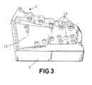
- the radar detector device object of the invention comprising two pieces (1.1) and (1.2) that make up the antenna in the form of a horn(1), a base (2) , inside which a middle part (3), a first (4) prepared integrated circuit board sits between the base of the horn shaped antenna (1) and the middle (intermediate) piece (riser) (3), and a second integrated circuit board disposed between the riser (3) and (2) base, as you can see in detail in Figure 4 .
- the two-piece (1.1), (1.2) are flattened and fix each other through a series of holes (1.3) performed on the workpiece (1.2) and through which passes about securing and locking screws, as shown in Figure 3
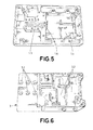
- the detector consists of an antenna in the form of horn made up of two parts (1.1) and (1.2) attached and secured, and which also defines a waveguide (1.7) where there is defined a specific design for a certain frequency filter (1.6) later said waveguide (1.7) continued on the underside of the pieces (1.1) and (1.2) attached, as you can see in Figure 5 , where you can see waveguide (1.9) in the central part there is a ridge (1.4), feature that other detectors filters do not have, and also the signal channeler presents is a length of the longest length of the used so far, and allows their direct contact with the track of the integrated circuit board. Also, you can see in Figure 5 , a series of resonant cavities and stages of reception (1.5) separators.
- the waveguide (1.7) includes an iris type filter (1.6), posts or plates, with double frequency, allowing the RF signal input in the device receiving bands without attenuation (bands K:24.125 Ghz Ka:33.7 - 36 GHz), attenuating the remaining frequencies, especially those of the internal local oscillator and the product of mixing with the intermediate frequencies.
- This differential characteristic is very important, since it is derive significant advantages of use and service, on the one hand, gets a smaller sensor size and weight, in addition to having a waveguide that allows to have a signal channeler and also has a significant length, allows the direct contact with the integrated circuit boar. it greatly improves the sensitivity of the detector.
Landscapes
- Engineering & Computer Science (AREA)
- Radar, Positioning & Navigation (AREA)
- Remote Sensing (AREA)
- Computer Networks & Wireless Communication (AREA)
- Physics & Mathematics (AREA)
- General Physics & Mathematics (AREA)
- Manufacturing & Machinery (AREA)
- Radar Systems Or Details Thereof (AREA)
- Waveguide Aerials (AREA)
Applications Claiming Priority (1)
| Application Number | Priority Date | Filing Date | Title |
|---|---|---|---|
| ES201131247U ES1076477Y (es) | 2011-12-01 | 2011-12-01 | Detector de radares |
Publications (2)
| Publication Number | Publication Date |
|---|---|
| EP2600166A2 true EP2600166A2 (fr) | 2013-06-05 |
| EP2600166A3 EP2600166A3 (fr) | 2014-05-07 |
Family
ID=45786927
Family Applications (1)
| Application Number | Title | Priority Date | Filing Date |
|---|---|---|---|
| EP12382367.6A Withdrawn EP2600166A3 (fr) | 2011-12-01 | 2012-09-19 | Dispositif de détection radar |
Country Status (2)
| Country | Link |
|---|---|
| EP (1) | EP2600166A3 (fr) |
| ES (1) | ES1076477Y (fr) |
Citations (3)
| Publication number | Priority date | Publication date | Assignee | Title |
|---|---|---|---|---|
| ES1046079U (es) | 2000-04-25 | 2000-11-01 | Cachaza Eusebio Bonjoch | Soporte para display de un detector comercial de radar. |
| ES1068228U (es) | 2008-06-06 | 2008-09-16 | Jose Luis Marina Moreno | Filtro amplificador para antenas de radar. |
| ES1069118U (es) | 2008-11-10 | 2009-02-01 | Demac, S.A. | Carcasa para un dispositivo detector de radares. |
Family Cites Families (3)
| Publication number | Priority date | Publication date | Assignee | Title |
|---|---|---|---|---|
| CA1187602A (fr) * | 1984-01-06 | 1985-05-21 | B.E.L.-Tronics Limited | Antenne cornet et melangeur pour detecteurs radar a microondes |
| JP3229564B2 (ja) * | 1997-06-10 | 2001-11-19 | ユピテル工業株式会社 | マイクロ波検出器 |
| US7388537B2 (en) * | 2005-10-14 | 2008-06-17 | Escort Inc. | Radar detector with reduced emissions |
-
2011
- 2011-12-01 ES ES201131247U patent/ES1076477Y/es not_active Expired - Fee Related
-
2012
- 2012-09-19 EP EP12382367.6A patent/EP2600166A3/fr not_active Withdrawn
Patent Citations (3)
| Publication number | Priority date | Publication date | Assignee | Title |
|---|---|---|---|---|
| ES1046079U (es) | 2000-04-25 | 2000-11-01 | Cachaza Eusebio Bonjoch | Soporte para display de un detector comercial de radar. |
| ES1068228U (es) | 2008-06-06 | 2008-09-16 | Jose Luis Marina Moreno | Filtro amplificador para antenas de radar. |
| ES1069118U (es) | 2008-11-10 | 2009-02-01 | Demac, S.A. | Carcasa para un dispositivo detector de radares. |
Also Published As
| Publication number | Publication date |
|---|---|
| EP2600166A3 (fr) | 2014-05-07 |
| ES1076477U (es) | 2012-03-14 |
| ES1076477Y (es) | 2012-06-08 |
Similar Documents
| Publication | Publication Date | Title |
|---|---|---|
| EP3571768B1 (fr) | Antenne cadre à détection de proximité intégrée | |
| EP2631672B1 (fr) | Structure d'altimètre de radar d'aéronef | |
| EP1438702A4 (fr) | Analyseur de trafic de vehicules | |
| US9640873B2 (en) | Radar device for a motor vehicle, securing device for a radar apparatus and method for manufacturing an absorption element for a radar apparatus | |
| US9341509B2 (en) | Frequency modulation continuous wave radar level meter and signal-tracking and phase-locking method for the same | |
| FI3378392T3 (fi) | Laitteistoja neurologisen tilan arviointiiin sähkömagneettisilla signaaleilla | |
| US20120194125A1 (en) | Contactless power transmission device | |
| WO2012128127A1 (fr) | Dispositif de télécommunication haute fréquence | |
| US12332371B2 (en) | Electronic radar device | |
| JP2005340730A (ja) | 電波吸収体 | |
| EP2600166A2 (fr) | Dispositif de détection radar | |
| KR20180092134A (ko) | 저주파 노이즈를 억제할 수 있는 구조를 갖는 레이더 | |
| CN106159395B (zh) | 腔体滤波器、双工器和射频拉远设备 | |
| EP1612754B1 (fr) | Avertisseur de danger | |
| CN207184464U (zh) | 一种3mm微波低噪声直检接收前端组件 | |
| US20200014108A1 (en) | Antenna device | |
| US20220021097A1 (en) | Active Waveguide Transition and RF Signal Communication System | |
| KR100975951B1 (ko) | 레이더 검출기의 혼 안테나 구조 | |
| CN223193407U (zh) | 检测仪的电控模块及检测仪 | |
| CN215008522U (zh) | 一种基于s波段谐波雷达射频接收端腔体滤波器 | |
| CN202651324U (zh) | 介质谐振腔带通滤波器 | |
| Kashiyama et al. | An RF Distance Sensor Utilizing Harmonic Signal from Rectenna for Power-Controlled Wireless Power Transmission System to Wearable Devices | |
| CN210693908U (zh) | 一种超小型超外差接收机腔体安装结构 | |
| CN204130701U (zh) | 双频卫星讯号接收装置 | |
| KR102034171B1 (ko) | 휴대 가능한 전자정보 장치의 운용 방법 |
Legal Events
| Date | Code | Title | Description |
|---|---|---|---|
| PUAI | Public reference made under article 153(3) epc to a published international application that has entered the european phase |
Free format text: ORIGINAL CODE: 0009012 |
|
| AK | Designated contracting states |
Kind code of ref document: A2 Designated state(s): AL AT BE BG CH CY CZ DE DK EE ES FI FR GB GR HR HU IE IS IT LI LT LU LV MC MK MT NL NO PL PT RO RS SE SI SK SM TR |
|
| AX | Request for extension of the european patent |
Extension state: BA ME |
|
| PUAL | Search report despatched |
Free format text: ORIGINAL CODE: 0009013 |
|
| AK | Designated contracting states |
Kind code of ref document: A3 Designated state(s): AL AT BE BG CH CY CZ DE DK EE ES FI FR GB GR HR HU IE IS IT LI LT LU LV MC MK MT NL NO PL PT RO RS SE SI SK SM TR |
|
| AX | Request for extension of the european patent |
Extension state: BA ME |
|
| RIC1 | Information provided on ipc code assigned before grant |
Ipc: H01Q 13/02 20060101ALI20140402BHEP Ipc: G01S 7/02 20060101AFI20140402BHEP |
|
| STAA | Information on the status of an ep patent application or granted ep patent |
Free format text: STATUS: THE APPLICATION IS DEEMED TO BE WITHDRAWN |
|
| 18D | Application deemed to be withdrawn |
Effective date: 20141108 |