EP2600136B1 - Apparatus and method for testing blow-out panels - Google Patents
Apparatus and method for testing blow-out panels Download PDFInfo
- Publication number
- EP2600136B1 EP2600136B1 EP12195098.4A EP12195098A EP2600136B1 EP 2600136 B1 EP2600136 B1 EP 2600136B1 EP 12195098 A EP12195098 A EP 12195098A EP 2600136 B1 EP2600136 B1 EP 2600136B1
- Authority
- EP
- European Patent Office
- Prior art keywords
- opening
- door
- chambers
- housing
- panel
- Prior art date
- Legal status (The legal status is an assumption and is not a legal conclusion. Google has not performed a legal analysis and makes no representation as to the accuracy of the status listed.)
- Active
Links
Images
Classifications
-
- G—PHYSICS
- G01—MEASURING; TESTING
- G01M—TESTING STATIC OR DYNAMIC BALANCE OF MACHINES OR STRUCTURES; TESTING OF STRUCTURES OR APPARATUS, NOT OTHERWISE PROVIDED FOR
- G01M99/00—Subject matter not provided for in other groups of this subclass
- G01M99/008—Subject matter not provided for in other groups of this subclass by doing functionality tests
-
- G—PHYSICS
- G01—MEASURING; TESTING
- G01M—TESTING STATIC OR DYNAMIC BALANCE OF MACHINES OR STRUCTURES; TESTING OF STRUCTURES OR APPARATUS, NOT OTHERWISE PROVIDED FOR
- G01M7/00—Vibration-testing of structures; Shock-testing of structures
- G01M7/08—Shock-testing
-
- G—PHYSICS
- G01—MEASURING; TESTING
- G01N—INVESTIGATING OR ANALYSING MATERIALS BY DETERMINING THEIR CHEMICAL OR PHYSICAL PROPERTIES
- G01N3/00—Investigating strength properties of solid materials by application of mechanical stress
- G01N3/08—Investigating strength properties of solid materials by application of mechanical stress by applying steady tensile or compressive forces
- G01N3/10—Investigating strength properties of solid materials by application of mechanical stress by applying steady tensile or compressive forces generated by pneumatic or hydraulic pressure
- G01N3/12—Pressure testing
-
- G—PHYSICS
- G01—MEASURING; TESTING
- G01N—INVESTIGATING OR ANALYSING MATERIALS BY DETERMINING THEIR CHEMICAL OR PHYSICAL PROPERTIES
- G01N3/00—Investigating strength properties of solid materials by application of mechanical stress
- G01N3/30—Investigating strength properties of solid materials by application of mechanical stress by applying a single impulsive force, e.g. by falling weight
-
- G—PHYSICS
- G01—MEASURING; TESTING
- G01N—INVESTIGATING OR ANALYSING MATERIALS BY DETERMINING THEIR CHEMICAL OR PHYSICAL PROPERTIES
- G01N2203/00—Investigating strength properties of solid materials by application of mechanical stress
- G01N2203/02—Details not specific for a particular testing method
- G01N2203/026—Specifications of the specimen
- G01N2203/0262—Shape of the specimen
- G01N2203/0278—Thin specimens
- G01N2203/0282—Two dimensional, e.g. tapes, webs, sheets, strips, disks or membranes
Definitions
- the present invention relates to a test apparatus and a method for testing blow-out panels.
- pressurized civil aircraft are equipped with special systems aiming at reducing pressure peaks which are generated in the event of a rapid decompression and which may weaken the fuselage structure.
- Such systems include blow-out panels that open at a certain value of differential pressure. The qualification and/or certification of the system is done through testing.
- blow-out panels are applied on decompression apertures in bulkheads separating two different environments. Should an excessive and potentially harmful pressure difference occur on the two opposite sides of the bulkhead, for example because of a gash in the fuselage, the blow-out panels are opened. This allows for a load compensation due to the pressure difference and prevent the entire bulkhead in which the panel is mounted from collapsing.
- blow-out panels are mounted on the floor, separating the Cargo Compartment Area and the EE-Bay Area. By tearing open, they prevent the floor from collapsing in the event of rapid decompression in one of the two environments. In other applications blow-out panels are mounted on the door that divides the cockpit from the cargo area, or on the bulkhead that separates the upper deck from the main deck.
- tests on blow-out panels were mainly carried out with rather complex and expensive equipment.
- Such equipment typically makes use of a test cylinder of large size, about 5-6 m long with a diameter of about 60 cm, inside which a vacuum is created by means of a vacuum machine.
- the panel to be tested is mounted adjacent to one of the end walls of the cylinder.
- the differential between the atmospheric pressure of the external environment and the vacuum in the cylinder causes the panel to break.
- the performance of the panel during its opening is studied by analyzing frames taken with a high speed digital camera.
- Rupture testing apparatus designed to test panels of various kinds, are known for example from US 5 424 634 , US 2 525 345 , EP 1 443 317 , US 3 600 940 and US 5 992 242 .
- the devices disclosed in these publications generally cause a test panel to break due to progressive and gradual application of pressure in one of two contiguous chambers located on opposite sides of the panel.
- the chambers are located within a housing and communicate directly with one another through an inner aperture which is closable by applying a panel thereupon. At least one of the two chambers communicates with a pressurized air inlet.
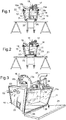
- the testing apparatus comprises an outer housing 10, of rigid material, preferably metal, inside which there are defined two contiguous inner chambers 11, 12, separated by a partition 13.
- the partition has an internal aperture 14 which may be closed by applying thereto a blow-out panel P to be tested. Blow-out panels are known in the art and therefore need not be described in detail herein.
- the partition 13 and the inner aperture 14, as well as those of the housing 10, are not essential for implementing the invention.
- the partition 13 in order to reduce the overall size of the apparatus and retain the panel adequately on the aperture 14, the partition 13 is configured as a flat frame which extends within the housing 10.
- the housing 10 is a box-like housing having an overall prismatic shape with a rectangular base, two vertical side walls, a top wall, a bottom wall and two opposite openable sides, vertical or inclined, as described in the following.
- the partition or frame 13 lies, in this example, in a vertical plane.
- the two chambers 11, 12 are in fluid communication with each other through an external connecting pipe comprising two tubular portions 15a, 15b which project each from a respective chamber 11, 12, and are mutually connected by means of a valve 16.
- the valve 16 serves to selectively establish or close a fluid communication between the two inner chambers 11, 12 through the connecting duct 15a, 15b.
- One of the two chambers, in this example chamber 11, is connected directly to a source of pressurized air, for example a blower or a compressor (not shown), via a pressurized air inlet 17.
- At least one of the two chambers 11, 12 may be put into communication with the outside through an opening 11a ( Figure 3 ) which is formed in an outer wall of the housing 10 and is hermetically closable.
- both chambers 11, 12 may be opened on the outside through a respective opening (only the opening 11a is visible in Figure 3 ).
- the openings may be located in two outer walls, in this example in two opposite walls, of the housing 10.
- Each opening is hermetically closable by a respective door 21, 22 which, when opened, puts the respective internal chamber 11, 12 in fluid communication with an outer ambient under atmospheric pressure.
- Each door 21, 22 may be associated with a respective quick opening device, selectively controllable to cause one of the two doors to open quickly.
- the quick opening device may include a latch mechanism 18, 19 associated with a quick release control 18a, 19a.
- two bolt mechanisms 18, 19 are provided, each driven open by a respective control 18a, 19b, preferably a pneumatic control.
- the communication valve 16 between the two chambers is opened. Activating the blower, the two chambers are pressurized through the inlet 17. Upon reaching a predetermined pressure level inside the chambers, the communication valve 16 is closed. Subsequently, by acting on the pneumatic control associated with one of two latch mechanisms, the operator opens one of the two doors 21 or 22, instantaneously bringing the pressure in one of the two chambers to atmospheric pressure, in this example chamber 11. The pressure within chamber 12, and the sudden decompression in only one of the two chambers results in a corresponding pressure differential between the two chambers which, depending on the size and strength of the panel P being tested, causes an opening/cracking in the panel P separating the environments of the two chambers.
- the doors of the apparatus are associated with thrust elements 24, which act between the outer body 10 and each door 21, 22, urging the doors towards their open positions.
- the thrust elements 24 are helical springs that remain elastically compressed, in contrast to their elastic force, by the respective doors when these are locked in the closed position by the latch mechanisms. Due to the spring members, upon unlocking the latch, the spring of the door which is unlocked releases instantly, thus favoring a quick opening of the door.
- these are preferably hinged at the bottom to the housing 10 with hinges or pivots 25, 26 along horizontal hinge axes.
- the openings 11a setting the inner chambers in communication with the outside and which are closed by doors 21, 22, are inclined with respect to a vertical plane, so that the top of the opening protrudes outwardly with respect to the lower part of the opening where the horizontal hinge axes are located. In this way, the unlocking of a selected latch leaves its door free to open by gravity, tilting downwards and outwards of the housing 10 ( Figures 2 and 3 ).
- the opening or breakage of the panel P being tested is monitored via pressure sensors schematically indicated S1-S3 which permits the measurement of the pressure in both chambers and the pressure differential between them.
- the pressure sensors are preferably mounted on the outside of the housing 10, and may include a first sensor S1 for measuring the pressure in chamber 11, a second sensor S2 for measuring the pressure in chamber 12, and a third sensor S3 that measures the pressure difference between the chambers 11 and 12.
- the pressure sensors are connected pneumatically to the chambers through pressure taps PR1, PR2 provided on the housing 10 and hoses with fast-coupling connectors.
- a system of microswitches may be used to measure the opening time of the panel being tested.
- Preferably four microswitches (not shown) are used, arranged in pairs.
- a first pair may be mounted in abutment on the panel P in a position in which it closes the inner aperture 14.
- the first pair of microswitches may be used to determine the instant in which the panel starts to move under the effect of the pressure difference applied on its opposite sides.
- the second pair of microswitches may be positioned at a predefined distance from the panel, in the opening direction, and allows to define the instant when the panel intercepts the switches after covering the predefined distance. The time interval between these two instants represents the opening time of the panel.
- a high-speed digital camera may be used to photograph the test through a window 23. The apparatus allows to measure both the value of the minimum pressure difference that causes the panel to open and the opening speed. It should be noted that the present invention is not limited by the choice of the type or mode of application of the pressure sensors and the microswitches, which may
- the door (21 or 22) which opens to cause breakage of the panel P is selected depending on the direction in which the rupture is desired, that is, in collaboration with the pressure gradient that is created on opening the chosen door.
- the panel P being tested is first constrained against one side of the partition 13, and then the door of the chamber towards which it is envisaged that the panel should break is opened.
- the panel inside the apparatus may be secured in other ways, taking care to close the two chambers substantially in an airtight manner relative to one another by a partition wall, and that part of the partition wall is constituted by the panel being tested, the two opposite faces of which are each directly facing a respective one of the chambers.
- the provision of two opening doors is beneficial because it allows to perform tests in a bidirectional mode without having to move the panel being tested.
- the advantages of being able to carry out tests in a bidirectional mode can be appreciated in cases where the test panels being tested are designed so that they can break in either direction, foreseeing that the event of rapid decompression may either occur in chamber 11 or in chamber 12.
- the door 21 of chamber 11 and, in a second test session, the door 22 of chamber 12 without having to remove the panel being tested and fit it back on its opposite side, as is necessary with conventional test equipment.
- the apparatus according to the present invention closely replicates the physical nature of the phenomenon reproducing the so-called “Sudden Decompression", since the sudden opening of one of the two doors (21 or 22) instantaneously reduces the pressure in the relative chamber down to the atmospheric pressure, whereas with conventional apparatus the simulation of the phenomenon is limited by the rate at which it is possible to create a vacuum (or decompression) in a chamber and thereby to provide the pressure difference able to break the panel being tested.
- the opening 11a has an width comparable to the size of the housing 10. In other embodiments, the opening 11a may be smaller.
- the opening 11 may have a size comparable to that of the panel being tested test, or even smaller, for example with an area of the order of a few tens of square centimeters. The broadness of the opening must not be so that it causes a gradual pressure drop in the inner chamber that is being opened. A large opening also facilitates manual access to the partition 13 and makes it easy to apply or fix the panel to be tested over the inner aperture 14.
- a further advantage accomplished by the apparatus according to the invention is the ability to reach values of differential pressure much higher than those that are achievable with conventional apparatus, the only limit being set by the sealing capability of the pressurizable chambers 11, 12.
- the maximum pressure differential with respect to the external environment may reach the value of approximately 1 bar.
- the apparatus of this disclosure is economical, compact and simple, which allows manufacturers to perform complex tests on-sites both in development and certification/qualification which would otherwise be outsourced.
Landscapes
- Physics & Mathematics (AREA)
- General Physics & Mathematics (AREA)
- General Health & Medical Sciences (AREA)
- Chemical & Material Sciences (AREA)
- Analytical Chemistry (AREA)
- Biochemistry (AREA)
- Life Sciences & Earth Sciences (AREA)
- Health & Medical Sciences (AREA)
- Immunology (AREA)
- Pathology (AREA)
- Examining Or Testing Airtightness (AREA)
- Investigating Strength Of Materials By Application Of Mechanical Stress (AREA)
- Preparation Of Clay, And Manufacture Of Mixtures Containing Clay Or Cement (AREA)
- Curing Cements, Concrete, And Artificial Stone (AREA)
Applications Claiming Priority (1)
| Application Number | Priority Date | Filing Date | Title |
|---|---|---|---|
| IT001099A ITTO20111099A1 (it) | 2011-11-30 | 2011-11-30 | Apparecchiatura di prova per pannelli di decompressione rapida. |
Publications (2)
| Publication Number | Publication Date |
|---|---|
| EP2600136A1 EP2600136A1 (en) | 2013-06-05 |
| EP2600136B1 true EP2600136B1 (en) | 2018-06-13 |
Family
ID=45420855
Family Applications (1)
| Application Number | Title | Priority Date | Filing Date |
|---|---|---|---|
| EP12195098.4A Active EP2600136B1 (en) | 2011-11-30 | 2012-11-30 | Apparatus and method for testing blow-out panels |
Country Status (4)
| Country | Link |
|---|---|
| US (1) | US8701478B2 (it) |
| EP (1) | EP2600136B1 (it) |
| ES (1) | ES2686931T3 (it) |
| IT (1) | ITTO20111099A1 (it) |
Families Citing this family (3)
| Publication number | Priority date | Publication date | Assignee | Title |
|---|---|---|---|---|
| DE102016201807A1 (de) * | 2016-02-05 | 2017-08-10 | Airbus Operations Gmbh | Strukturtestanordnung und Verfahren zur Durchführung von Strukturtests |
| CN106501071B (zh) * | 2016-11-29 | 2019-01-04 | 中国民航大学 | 一种简单的机身蒙皮均布增压疲劳实验机及其模拟方法 |
| CN114813363A (zh) * | 2021-11-12 | 2022-07-29 | 重庆翔源制冷设备股份有限公司 | 钢构板件及精密仪器承受准静压测试装置 |
Family Cites Families (14)
| Publication number | Priority date | Publication date | Assignee | Title |
|---|---|---|---|---|
| US2525345A (en) * | 1948-05-20 | 1950-10-10 | Perkins & Son Inc B F | Machine for rupturing paper and the like for testing purposes |
| US2826063A (en) * | 1954-08-23 | 1958-03-11 | Perkins & Son Inc B F | Hydraulic rupture testing machine |
| US2907200A (en) * | 1956-02-14 | 1959-10-06 | Aaron G Roberts | Apparatus for measuring abrasion resistance |
| US3580050A (en) * | 1969-05-19 | 1971-05-25 | Paul H R Waldron | Testing device for stretchable sheet materials under simultaneous distortion in three dimensions |
| US3600940A (en) * | 1969-06-09 | 1971-08-24 | Cady E J & Co | Automatic burst tester |
| US3875789A (en) * | 1974-03-26 | 1975-04-08 | American Can Co | Apparatus for testing end closures |
| US3958448A (en) * | 1974-10-10 | 1976-05-25 | Aluminum Company Of America | Test apparatus for pressurized container and method |
| US4282744A (en) * | 1979-11-02 | 1981-08-11 | Western Electric Co., Inc. | Leak testing hermetically sealed electronic articles |
| US4395917A (en) * | 1981-10-26 | 1983-08-02 | Libbey-Owens-Ford Company | Apparatus for testing glass |
| US4715215A (en) * | 1985-04-25 | 1987-12-29 | The Aro Corporation | Method and apparatus for testing the fluid-tight sealed integrity of a hermetically-sealed package in a rapidly-stabilized environment |
| US4967602A (en) * | 1989-05-03 | 1990-11-06 | Measurex Corporation | Pneumatic strength tester for sheet materials |
| US5424634A (en) * | 1994-02-18 | 1995-06-13 | International Business Machines Corporation | Non-destructive flex testing method and means |
| US5992242A (en) * | 1998-05-04 | 1999-11-30 | Lsi Logic Corporation | Silicon wafer or die strength test fixture using high pressure fluid |
| GB0302297D0 (en) * | 2003-01-31 | 2003-03-05 | United Biscuits Ltd | Flour and Dough Evaluation Apparatus |
-
2011
- 2011-11-30 IT IT001099A patent/ITTO20111099A1/it unknown
-
2012
- 2012-11-30 US US13/689,834 patent/US8701478B2/en active Active
- 2012-11-30 ES ES12195098.4T patent/ES2686931T3/es active Active
- 2012-11-30 EP EP12195098.4A patent/EP2600136B1/en active Active
Non-Patent Citations (1)
| Title |
|---|
| None * |
Also Published As
| Publication number | Publication date |
|---|---|
| US8701478B2 (en) | 2014-04-22 |
| ES2686931T3 (es) | 2018-10-22 |
| EP2600136A1 (en) | 2013-06-05 |
| ITTO20111099A1 (it) | 2013-05-31 |
| US20130133414A1 (en) | 2013-05-30 |
Similar Documents
| Publication | Publication Date | Title |
|---|---|---|
| EP2600136B1 (en) | Apparatus and method for testing blow-out panels | |
| JPH10513256A (ja) | 可変容積テスト・チャンバ | |
| US20040094670A1 (en) | Pressure responsive blowout latch with reservoir | |
| US10399660B2 (en) | Decompression panel assembly and methods of assembling the same | |
| EP2799837B1 (en) | Pressure test containment vessel | |
| CA2962033C (en) | Fire suppression system | |
| EP3743329B1 (en) | Modular, palletized system for a deployable sensor | |
| US10279887B2 (en) | Decompression panel assembly and methods of assembling the same | |
| EP3208491B1 (en) | Load relief tie rod | |
| EP3020636B1 (en) | Self-dampening tie-rod | |
| CA2489598C (en) | Pressure responsive blowout latch with reservoir | |
| US6871821B2 (en) | Cockpit door of aircraft | |
| EP1856498B1 (en) | Pressure-difference warning system | |
| CN112240857B (zh) | 一种地下管廊内燃气舱防火墙抗闪爆冲击的模拟试验装置 | |
| US20220404181A1 (en) | Transportable testing arrangement | |
| CN115571374B (zh) | 一种多极爆炸减压模拟装置 | |
| CA2717911C (en) | Rapid decompression detection system and method | |
| JP2005028117A (ja) | 圧力室のためのラッチ・システム及び方法 | |
| US7891607B2 (en) | Pressure sensor device | |
| JPH04351936A (ja) | 容器の強度試験方法および装置 | |
| CN211418335U (zh) | 卫星运输箱 | |
| RU2376206C1 (ru) | Система открытия аварийного выхода | |
| US20250002149A1 (en) | Venting systems and methods for an internal cabin of an aircraft | |
| CA2964252C (en) | Decompression panel assembly and methods of assembling the same | |
| Pratt | Rapid decompression of pressurized aircraft fuselages |
Legal Events
| Date | Code | Title | Description |
|---|---|---|---|
| PUAI | Public reference made under article 153(3) epc to a published international application that has entered the european phase |
Free format text: ORIGINAL CODE: 0009012 |
|
| AK | Designated contracting states |
Kind code of ref document: A1 Designated state(s): AL AT BE BG CH CY CZ DE DK EE ES FI FR GB GR HR HU IE IS IT LI LT LU LV MC MK MT NL NO PL PT RO RS SE SI SK SM TR |
|
| AX | Request for extension of the european patent |
Extension state: BA ME |
|
| 17P | Request for examination filed |
Effective date: 20131107 |
|
| RBV | Designated contracting states (corrected) |
Designated state(s): AL AT BE BG CH CY CZ DE DK EE ES FI FR GB GR HR HU IE IS IT LI LT LU LV MC MK MT NL NO PL PT RO RS SE SI SK SM TR |
|
| GRAP | Despatch of communication of intention to grant a patent |
Free format text: ORIGINAL CODE: EPIDOSNIGR1 |
|
| INTG | Intention to grant announced |
Effective date: 20171211 |
|
| GRAS | Grant fee paid |
Free format text: ORIGINAL CODE: EPIDOSNIGR3 |
|
| GRAA | (expected) grant |
Free format text: ORIGINAL CODE: 0009210 |
|
| RIN1 | Information on inventor provided before grant (corrected) |
Inventor name: CUOMO, SALVATORE Inventor name: DE MAIO, BIAGIO Inventor name: COVINO, IGINO Inventor name: CAPONE, GRAZIANO Inventor name: RAINONE, FRANCESCO |
|
| RAP1 | Party data changed (applicant data changed or rights of an application transferred) |
Owner name: LEONARDO S.P.A. |
|
| AK | Designated contracting states |
Kind code of ref document: B1 Designated state(s): AL AT BE BG CH CY CZ DE DK EE ES FI FR GB GR HR HU IE IS IT LI LT LU LV MC MK MT NL NO PL PT RO RS SE SI SK SM TR |
|
| REG | Reference to a national code |
Ref country code: GB Ref legal event code: FG4D |
|
| REG | Reference to a national code |
Ref country code: CH Ref legal event code: EP Ref country code: AT Ref legal event code: REF Ref document number: 1008987 Country of ref document: AT Kind code of ref document: T Effective date: 20180615 |
|
| REG | Reference to a national code |
Ref country code: IE Ref legal event code: FG4D |
|
| REG | Reference to a national code |
Ref country code: DE Ref legal event code: R096 Ref document number: 602012047379 Country of ref document: DE |
|
| REG | Reference to a national code |
Ref country code: NL Ref legal event code: MP Effective date: 20180613 |
|
| REG | Reference to a national code |
Ref country code: ES Ref legal event code: FG2A Ref document number: 2686931 Country of ref document: ES Kind code of ref document: T3 Effective date: 20181022 |
|
| REG | Reference to a national code |
Ref country code: LT Ref legal event code: MG4D |
|
| PG25 | Lapsed in a contracting state [announced via postgrant information from national office to epo] |
Ref country code: NO Free format text: LAPSE BECAUSE OF FAILURE TO SUBMIT A TRANSLATION OF THE DESCRIPTION OR TO PAY THE FEE WITHIN THE PRESCRIBED TIME-LIMIT Effective date: 20180913 Ref country code: BG Free format text: LAPSE BECAUSE OF FAILURE TO SUBMIT A TRANSLATION OF THE DESCRIPTION OR TO PAY THE FEE WITHIN THE PRESCRIBED TIME-LIMIT Effective date: 20180913 Ref country code: CY Free format text: LAPSE BECAUSE OF FAILURE TO SUBMIT A TRANSLATION OF THE DESCRIPTION OR TO PAY THE FEE WITHIN THE PRESCRIBED TIME-LIMIT Effective date: 20180613 Ref country code: SE Free format text: LAPSE BECAUSE OF FAILURE TO SUBMIT A TRANSLATION OF THE DESCRIPTION OR TO PAY THE FEE WITHIN THE PRESCRIBED TIME-LIMIT Effective date: 20180613 Ref country code: FI Free format text: LAPSE BECAUSE OF FAILURE TO SUBMIT A TRANSLATION OF THE DESCRIPTION OR TO PAY THE FEE WITHIN THE PRESCRIBED TIME-LIMIT Effective date: 20180613 Ref country code: LT Free format text: LAPSE BECAUSE OF FAILURE TO SUBMIT A TRANSLATION OF THE DESCRIPTION OR TO PAY THE FEE WITHIN THE PRESCRIBED TIME-LIMIT Effective date: 20180613 |
|
| PG25 | Lapsed in a contracting state [announced via postgrant information from national office to epo] |
Ref country code: LV Free format text: LAPSE BECAUSE OF FAILURE TO SUBMIT A TRANSLATION OF THE DESCRIPTION OR TO PAY THE FEE WITHIN THE PRESCRIBED TIME-LIMIT Effective date: 20180613 Ref country code: HR Free format text: LAPSE BECAUSE OF FAILURE TO SUBMIT A TRANSLATION OF THE DESCRIPTION OR TO PAY THE FEE WITHIN THE PRESCRIBED TIME-LIMIT Effective date: 20180613 Ref country code: GR Free format text: LAPSE BECAUSE OF FAILURE TO SUBMIT A TRANSLATION OF THE DESCRIPTION OR TO PAY THE FEE WITHIN THE PRESCRIBED TIME-LIMIT Effective date: 20180914 Ref country code: RS Free format text: LAPSE BECAUSE OF FAILURE TO SUBMIT A TRANSLATION OF THE DESCRIPTION OR TO PAY THE FEE WITHIN THE PRESCRIBED TIME-LIMIT Effective date: 20180613 |
|
| REG | Reference to a national code |
Ref country code: AT Ref legal event code: MK05 Ref document number: 1008987 Country of ref document: AT Kind code of ref document: T Effective date: 20180613 |
|
| PG25 | Lapsed in a contracting state [announced via postgrant information from national office to epo] |
Ref country code: NL Free format text: LAPSE BECAUSE OF FAILURE TO SUBMIT A TRANSLATION OF THE DESCRIPTION OR TO PAY THE FEE WITHIN THE PRESCRIBED TIME-LIMIT Effective date: 20180613 |
|
| PG25 | Lapsed in a contracting state [announced via postgrant information from national office to epo] |
Ref country code: EE Free format text: LAPSE BECAUSE OF FAILURE TO SUBMIT A TRANSLATION OF THE DESCRIPTION OR TO PAY THE FEE WITHIN THE PRESCRIBED TIME-LIMIT Effective date: 20180613 Ref country code: PL Free format text: LAPSE BECAUSE OF FAILURE TO SUBMIT A TRANSLATION OF THE DESCRIPTION OR TO PAY THE FEE WITHIN THE PRESCRIBED TIME-LIMIT Effective date: 20180613 Ref country code: IS Free format text: LAPSE BECAUSE OF FAILURE TO SUBMIT A TRANSLATION OF THE DESCRIPTION OR TO PAY THE FEE WITHIN THE PRESCRIBED TIME-LIMIT Effective date: 20181013 Ref country code: RO Free format text: LAPSE BECAUSE OF FAILURE TO SUBMIT A TRANSLATION OF THE DESCRIPTION OR TO PAY THE FEE WITHIN THE PRESCRIBED TIME-LIMIT Effective date: 20180613 Ref country code: AT Free format text: LAPSE BECAUSE OF FAILURE TO SUBMIT A TRANSLATION OF THE DESCRIPTION OR TO PAY THE FEE WITHIN THE PRESCRIBED TIME-LIMIT Effective date: 20180613 Ref country code: CZ Free format text: LAPSE BECAUSE OF FAILURE TO SUBMIT A TRANSLATION OF THE DESCRIPTION OR TO PAY THE FEE WITHIN THE PRESCRIBED TIME-LIMIT Effective date: 20180613 Ref country code: SK Free format text: LAPSE BECAUSE OF FAILURE TO SUBMIT A TRANSLATION OF THE DESCRIPTION OR TO PAY THE FEE WITHIN THE PRESCRIBED TIME-LIMIT Effective date: 20180613 |
|
| PG25 | Lapsed in a contracting state [announced via postgrant information from national office to epo] |
Ref country code: SM Free format text: LAPSE BECAUSE OF FAILURE TO SUBMIT A TRANSLATION OF THE DESCRIPTION OR TO PAY THE FEE WITHIN THE PRESCRIBED TIME-LIMIT Effective date: 20180613 |
|
| REG | Reference to a national code |
Ref country code: DE Ref legal event code: R097 Ref document number: 602012047379 Country of ref document: DE |
|
| PLBE | No opposition filed within time limit |
Free format text: ORIGINAL CODE: 0009261 |
|
| STAA | Information on the status of an ep patent application or granted ep patent |
Free format text: STATUS: NO OPPOSITION FILED WITHIN TIME LIMIT |
|
| 26N | No opposition filed |
Effective date: 20190314 |
|
| PG25 | Lapsed in a contracting state [announced via postgrant information from national office to epo] |
Ref country code: SI Free format text: LAPSE BECAUSE OF FAILURE TO SUBMIT A TRANSLATION OF THE DESCRIPTION OR TO PAY THE FEE WITHIN THE PRESCRIBED TIME-LIMIT Effective date: 20180613 Ref country code: DK Free format text: LAPSE BECAUSE OF FAILURE TO SUBMIT A TRANSLATION OF THE DESCRIPTION OR TO PAY THE FEE WITHIN THE PRESCRIBED TIME-LIMIT Effective date: 20180613 |
|
| REG | Reference to a national code |
Ref country code: CH Ref legal event code: PL |
|
| PG25 | Lapsed in a contracting state [announced via postgrant information from national office to epo] |
Ref country code: LU Free format text: LAPSE BECAUSE OF NON-PAYMENT OF DUE FEES Effective date: 20181130 Ref country code: MC Free format text: LAPSE BECAUSE OF FAILURE TO SUBMIT A TRANSLATION OF THE DESCRIPTION OR TO PAY THE FEE WITHIN THE PRESCRIBED TIME-LIMIT Effective date: 20180613 |
|
| REG | Reference to a national code |
Ref country code: BE Ref legal event code: MM Effective date: 20181130 |
|
| REG | Reference to a national code |
Ref country code: IE Ref legal event code: MM4A |
|
| PG25 | Lapsed in a contracting state [announced via postgrant information from national office to epo] |
Ref country code: CH Free format text: LAPSE BECAUSE OF NON-PAYMENT OF DUE FEES Effective date: 20181130 Ref country code: LI Free format text: LAPSE BECAUSE OF NON-PAYMENT OF DUE FEES Effective date: 20181130 |
|
| PG25 | Lapsed in a contracting state [announced via postgrant information from national office to epo] |
Ref country code: IE Free format text: LAPSE BECAUSE OF NON-PAYMENT OF DUE FEES Effective date: 20181130 |
|
| PG25 | Lapsed in a contracting state [announced via postgrant information from national office to epo] |
Ref country code: BE Free format text: LAPSE BECAUSE OF NON-PAYMENT OF DUE FEES Effective date: 20181130 Ref country code: AL Free format text: LAPSE BECAUSE OF FAILURE TO SUBMIT A TRANSLATION OF THE DESCRIPTION OR TO PAY THE FEE WITHIN THE PRESCRIBED TIME-LIMIT Effective date: 20180613 |
|
| PG25 | Lapsed in a contracting state [announced via postgrant information from national office to epo] |
Ref country code: MT Free format text: LAPSE BECAUSE OF NON-PAYMENT OF DUE FEES Effective date: 20181130 |
|
| PG25 | Lapsed in a contracting state [announced via postgrant information from national office to epo] |
Ref country code: TR Free format text: LAPSE BECAUSE OF FAILURE TO SUBMIT A TRANSLATION OF THE DESCRIPTION OR TO PAY THE FEE WITHIN THE PRESCRIBED TIME-LIMIT Effective date: 20180613 |
|
| PG25 | Lapsed in a contracting state [announced via postgrant information from national office to epo] |
Ref country code: PT Free format text: LAPSE BECAUSE OF FAILURE TO SUBMIT A TRANSLATION OF THE DESCRIPTION OR TO PAY THE FEE WITHIN THE PRESCRIBED TIME-LIMIT Effective date: 20180613 |
|
| PG25 | Lapsed in a contracting state [announced via postgrant information from national office to epo] |
Ref country code: HU Free format text: LAPSE BECAUSE OF FAILURE TO SUBMIT A TRANSLATION OF THE DESCRIPTION OR TO PAY THE FEE WITHIN THE PRESCRIBED TIME-LIMIT; INVALID AB INITIO Effective date: 20121130 Ref country code: MK Free format text: LAPSE BECAUSE OF NON-PAYMENT OF DUE FEES Effective date: 20180613 |
|
| PGFP | Annual fee paid to national office [announced via postgrant information from national office to epo] |
Ref country code: DE Payment date: 20251128 Year of fee payment: 14 |
|
| PGFP | Annual fee paid to national office [announced via postgrant information from national office to epo] |
Ref country code: GB Payment date: 20251127 Year of fee payment: 14 |
|
| PGFP | Annual fee paid to national office [announced via postgrant information from national office to epo] |
Ref country code: IT Payment date: 20251119 Year of fee payment: 14 |
|
| PGFP | Annual fee paid to national office [announced via postgrant information from national office to epo] |
Ref country code: FR Payment date: 20251125 Year of fee payment: 14 |
|
| PGFP | Annual fee paid to national office [announced via postgrant information from national office to epo] |
Ref country code: ES Payment date: 20251201 Year of fee payment: 14 |