EP2599926A1 - Sanitary cleaning device - Google Patents
Sanitary cleaning device Download PDFInfo
- Publication number
- EP2599926A1 EP2599926A1 EP11812536.8A EP11812536A EP2599926A1 EP 2599926 A1 EP2599926 A1 EP 2599926A1 EP 11812536 A EP11812536 A EP 11812536A EP 2599926 A1 EP2599926 A1 EP 2599926A1
- Authority
- EP
- European Patent Office
- Prior art keywords
- water
- electrolytic cell
- flow channel
- nozzle
- strainer
- Prior art date
- Legal status (The legal status is an assumption and is not a legal conclusion. Google has not performed a legal analysis and makes no representation as to the accuracy of the status listed.)
- Granted
Links
Images




Classifications
-
- E—FIXED CONSTRUCTIONS
- E03—WATER SUPPLY; SEWERAGE
- E03D—WATER-CLOSETS OR URINALS WITH FLUSHING DEVICES; FLUSHING VALVES THEREFOR
- E03D9/00—Sanitary or other accessories for lavatories ; Devices for cleaning or disinfecting the toilet room or the toilet bowl; Devices for eliminating smells
- E03D9/08—Devices in the bowl producing upwardly-directed sprays; Modifications of the bowl for use with such devices ; Bidets; Combinations of bowls with urinals or bidets; Hot-air or other devices mounted in or on the bowl, urinal or bidet for cleaning or disinfecting
-
- E—FIXED CONSTRUCTIONS
- E03—WATER SUPPLY; SEWERAGE
- E03D—WATER-CLOSETS OR URINALS WITH FLUSHING DEVICES; FLUSHING VALVES THEREFOR
- E03D9/00—Sanitary or other accessories for lavatories ; Devices for cleaning or disinfecting the toilet room or the toilet bowl; Devices for eliminating smells
- E03D9/005—Devices adding disinfecting or deodorising agents to the bowl
Definitions
- a seventh invention is the sanitary washing apparatus of the first invention wherein the strainer is provided attachably and rem ovably.
- a eighth invention is the sanitary washing apparatus of the second invention wherein the strainer is provided attachably and removably.
- a eleventh invention is the sanitary washing apparatus of the ninth invention wherein the strainer is fixed to a fixing portion of the flow channel, and a surface energy of the fixing portion is greater than the surface energy of the strainer.
- a twelfth invention is the sanitary washing apparatus of the tenth invention wherein the strainer is fixed to a fixing portion of the flow channel, and a surface energy of the fixing portion is greater than the surface energy of the strainer.
- An electrolytic cell unit (an electrolytic cell) 450 that is capable of producing sterilizing water is provided downstream of the warm water heater 441.
- the nozzle 473 and the flow channel 20 downstream of the electrolytic cell unit 450 are sterilized by the sterilizing water produced by the electrolytic cell unit 450.
- the control unit 405 does not provide the current to the anode plate 454 and the cathode plate 455 of the electrolytic cell unit 450, the central body of the nozzle 473 is physically washed by the water squirted from the water discharge unit 479.
- the control unit 405 starts the flow of current to the electrolytic cell unit 450 and causes the electrolytic cell unit 450 to produce the sterilizing water (timing t109). Also, the control unit 405 stops the flow of current to the warm water heater 441 or reduces the current amount to the warm water heater 441 (timing t109).
- reducing the current amount is taken to be the reduction of the current amount such that the temperature of the water heated by the warm water heater 441 is a temperature that is lower than the set value of the warm water temperature when executing the body wash.
- the set value of the warm water temperature when executing the body wash is, for example, about 30 to 40 °C.
- the control unit 405 starts the flow of current to the electrolytic cell unit 450 after replacing the warm water of the electrolytic cell unit 450 with water that is unheated by opening the solenoid valve 431 to discharge the warm water of the electrolytic cell unit 450. Therefore, the warm water inside the electrolytic cell unit 450 is replaced with water that is unheated when the control unit 405 starts the flow of current to the electrolytic cell unit 450. Thereby, the increase of the production of the scale can be suppressed.
- the scale becomes easy to produce at the electrolytic cell unit 450 and the heat exchanger unit 440. Therefore, to suppress the increase of the production of the scale and suppress the decrease of the production efficiency of the hypochlorous acid, it is necessary to suppress the increase of the production of the scale in the electrolytic cell unit 450 and the heat exchanger unit 440.
- the flow of the electrolyzed water having the high pH is subjected to flow channel resistance at the connection portion 600a (the contraction portion) of the vacuum breaker 600 that has the diameter that is smaller than the inner diameter of the flexible tube C; and the electrolyzed water is mixed.
- the reaction of Formula (3) progresses, the growth of the scale having the micro scale pieces that were suspended in the electrolyzed water as nuclei is promoted; and the scale occurs at the connection portion 600a vicinity. It is considered that the micro scale pieces occur when reversing the polarities of the electrodes of the electrolytic cell unit 450 and are discharged from the electrolytic cell unit 450.
- the position of the strainer S prefferably be proximal to the downstream side of the connection portion 600a where the mixing is sufficiently performed and the unbalanced pH subsides. I n the case where the strainer S is disposed inside the flow channel where the pH is in the unbalanced state, there is a risk that the scale may be produced on the downstream side of the strainer S; and sufficient effects cannot be expected.
- control unit 405 does not provide the current to the electrolytic cell unit 450 and does not cause the electrolytic cell unit 450 to produce the sterilizing water. Also, the control unit 405 causes the warm water heater 441 to heat the water by setting the warm water heater 441 to the "pre-wash mode, the main wash mode, and the post-wash mode.” Therefore, the portion of the water discharge ports 474 is washed by the warm water that the water discharge ports 474 themselves discharge.
- the control unit 405 switches the flow rate switch valve 471 and the flow channel switch valve 472 from the “origin” to "SC” and makes it possible to discharge from all of the water discharge ports 474 for the "bottom wash” and the "bidet wash” (timing t216). Further, the control unit 405 opens the solenoid valve 431 (timing t216).
- the control unit 405 stops the flow of current to the warm water heater 441 or reduces the current amount to the warm water heater 441 when starting the flow of current to the electrolytic cell unit 450, causing the electrolytic cell unit 450 to produce the sterilizing water, and sterilizing the nozzle 473. Therefore, when the control unit 405 starts the flow of current to the electrolytic cell unit 450, the water inside the electrolytic cell unit 450 is water that is unheated. Or, when the control unit 405 starts the flow of current to the electrolytic cell unit 450, the warm water inside the electrolytic cell unit 450 is replaced with water that is unheated. Thereby, the increase of the production of the scale can be suppressed.
Landscapes
- Health & Medical Sciences (AREA)
- Public Health (AREA)
- Epidemiology (AREA)
- Life Sciences & Earth Sciences (AREA)
- Engineering & Computer Science (AREA)
- Hydrology & Water Resources (AREA)
- Water Supply & Treatment (AREA)
- Molecular Biology (AREA)
- Bidet-Like Cleaning Device And Other Flush Toilet Accessories (AREA)
Abstract
Description
- An aspect of the invention generally relates to a sanitary washing apparatus and specifically relates to a sanitary washing apparatus that uses water to wash the "bottom" and the like of a user sitting on a western-style sit-down toilet.
- A washing nozzle configured to wash the body such as the "bottom" and the like of a user sitting on a toilet seat squirts wash water onto the body in the state in which at least a portion of the washing nozzle is exposed (advanced) outside a casing to which prescribed functional parts such as the washing nozzle, a warm water tank, etc., are mounted. Therefore, there is a risk that liquid waste and/or solid waste may adhere to the washing nozzle. Conversely, there exist sanitary washing apparatuses to rinse away and remove the liquid waste and/or the solid waste adhered to the washing nozzle prior to and after performing the body wash. Thereby, the washing nozzle is kept clean.
- However, even in the case where the liquid waste and/or the solid waste adhered to the washing nozzle are rinsed away, there are cases where bacteria propagates on the washing nozzle over time in humid environments such as that of the toilet room. More specifically, there is a risk that, for example, bacteria such as methylobacterium called pink slime and the like and black mold, etc., that occur on the bowl face and the like of the toilet may adhere to the washing nozzle; and the bacteria may propagate on the washing nozzle. Then, for example, in the case where bacteria called biofilms and the like and collections of secretions of the bacteria (slime and black dirt) form due to the propagation of the bacteria, it becomes difficult to remove such biofilms in a normal nozzle wash such as that described above.
- Conversely, there is a private part cleansing apparatus in which an electrolytic cell is included as a nozzle wash production unit (Patent Document 1). In the private part cleansing apparatus according to
Patent Document 1 , in the case where service water is used as the wash water, chlorine included in the service water undergoes a chemical change into hypochlorous acid due to electrolysis and can perform cleaning as an acidic chemical liquid. Therefore, effective cleaning of particularly the dirt due to ammonia, etc., is possible. - In such a case, it is more favorable for the electrolytic cell to be provided at a portion more proximal to the nozzle to efficiently utilize the wash water produced by the electrolytic cell. Therefore, there is a private part cleansing apparatus in which the electrolytic cell is provided in the flow channel downstream of the warm water tank (Patent Document 2). In the private part cleansing apparatus according to the
Patent Document 2, electrolyzed water is produced by warm water being electrolyzed inside the electrolytic cell. Then, a nozzle wash unit squirts the warm water as the wash water onto the bottom wash nozzle and the bidet wash nozzle. - However, when the electrolyzed water is produced by the warm water being electrolyzed, calcium carbonate and the like such as so-called "scale," etc., are produced easily. It is problematic when the scale adheres to the electrodes of the electrolytic cell because the production capability of the electrolyzed water decreases.
- Conversely, the private part cleansing apparatus according to
Patent Document 2 causes the polarity of the voltage applied to the electrodes to reverse to remove the scale. Similarly, there is a control apparatus of an electrolytic cell that includes a polarity switch unit configured to switch the polarities of the anode side and the cathode side of the electrodes of the electrolytic cell (Patent Document 3). According to the private part cleansing apparatus and the control apparatus of the electrolytic cell according toPatent Documents - However, in a sanitary washing apparatus having a relatively narrow flow channel, there is a risk that the flow channel may clog due to the scale that peels from the electrodes.
-
- [Patent Citation 1]
JP 3487447 - [Patent Citation 2]
JP 2005-155098 A - [Patent Citation 3]
JP H10-34156 A - The invention was made based on the relevant problems and is directed to provide a sanitary washing apparatus that can suppress clogging due to the scale of the flow channel.
- According to an aspect of the invention, a sanitary washing apparatus, characterized by: a nozzle having a water discharge port, the nozzle being configured to wash a body of a user by squirting water from the water discharge port; a flow channel configured to guide water supplied from a water supply source toward the water discharge port; an electrolytic cell provided at an intermediate portion of the flow channel, the electrolytic cell being capable of producing sterilizing water; and a nozzle wash unit configured to wash or sterilize the nozzle with the sterilizing water produced by the electrolytic cell, a contraction portion being formed downstream from the electrolytic cell, a flow channel cross-sectional area being smaller at the contraction portion than upstream from the electrolytic cell, a strainer being disposed in the flow channel further downstream from the contraction portion.
-
- [
Fig. 1 ]
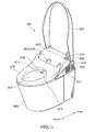
FIG. 1 is a schematic perspective view showing a toilet apparatus including a sanitary washing apparatus according to an embodiment of the invention. - [
Fig. 2 ]
FIG. 2 is a block diagram showing relevant components of the sanitary washing apparatus according to the embodiment. - [
Fig. 3 ]
FIG. 3 is a schematic perspective view showing a specific example of a nozzle unit of the embodiment. - [
Fig. 4 ]
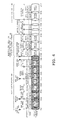
FIG. 4 is a conceptual schematic view showing the schematic of the operations and the state of the flow channel of the sanitary washing apparatus according to the embodiment. - [
Fig. 5 ]
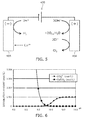
FIG. 5 is a schematic plan view describing the scale produced in the electrolytic cell unit of the embodiment. - [
Fig. 6 ]
FIG. 6 is a graph showing the change of the dissolution amounts of carbonate ions and calcium carbonate based on the change of the pH. - [
Fig. 7 ]
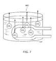
FIG. 7 is a schematic plan view describing the scale produced in the heat exchanger unit of the embodiment. - [
Fig. 8 ]
FIG. 8 is a graph showing the change of the dissolution amount of the calcium carbonate based on the temperature change. - [
Fig. 9 ]
FIG. 9 is a schematic view showing the flow channel downstream from the electrolytic cell. - [
Fig. 10 ]
FIG. 10 is a schematic partially enlarged view ofFIG. 9 . - [
Fig. 11 ]
FIG. 11 is a timing chart showing a specific example of the operations of the sanitary washing apparatus according to the embodiment. - A first invention is a sanitary washing apparatus characterized by: a nozzle having a water discharge port, the nozzle being configured to wash a body of a user by squirting water from the water discharge port; a flow channel configured to guide water supplied from a water supply source toward the water discharge port; an electrolytic cell provided at an intermediate portion of the flow channel, the electrolytic cell being capable of producing sterilizing water; and a nozzle wash unit configured to wash or sterilize the nozzle with the sterilizing water produced by the electrolytic cell, a contraction portion being formed downstream from the electrolytic cell, a flow channel cross-sectional area being smaller at the contraction portion than upstream from the electrolytic cell, a strainer being disposed further downstream from the contraction portion.
- According to the sanitary washing apparatus, clogging of the flow channel due to scale downstream from the strainer can be suppressed because the strainer captures, of course, the scale discharged from the electrolytic cell but also captures scale by the contraction portion being formed in a region of unstable electrolyzed water discharged from the electrolytic cell where there is a risk that the scale may precipitate and by the precipitation of the scale and growth of the scale being deliberately induced by turbulence of the flow occurring due to the contraction portion.
- Inside the electrolytic cell, although the pH (the "pay-hah") on the cathode side is high due to the electrolysis of the service water and the state at the electrode surface is a state in which the scale forms easily, the state at a water region slightly separated from the electrode surface also is a state in which the pH is high. Although the electrolyzed water discharged from the electrolytic cell flows down the flow channel, the state of the pH is a high and unstable state at the flow region just outside the electrolytic cell; and therefore, it may be conjectured that there is a risk that scale may precipitate and/or small pieces of scale, etc., produced by the electrolytic cell may grow. It may be conjectured that such precipitation and/or growth of the scale occurs due to the flow of the electrolyzed water that flows out from the electrolytic cell becoming turbulent. Therefore, it is possible to suppress unforeseen scale precipitation and growth on the downstream side of the strainer by reducing the diameter of the flow channel, deliberately precipitating the scale at the reduced-diameter portion, and capturing the scale with the strainer.
- A second invention is A sanitary washing apparatus, characterized by: a nozzle disposed at a toilet upper portion, the nozzle having a water discharge port, the nozzle being configured to discharge water from the water discharge port toward a bowl face of the toilet; a flow channel configured to guide water supplied from a water supply source toward the water discharge port; an electrolytic cell provided at an intermediate portion of the flow channel, the electrolytic cell being capable of producing sterilizing water; and a bowl wash unit configured to wash or sterilize the bowl face with the sterilizing water produced by the electrolytic cell, a contraction portion being formed downstream from the electrolytic cell, a flow channel cross-sectional area being smaller at the contraction portion than upstream from the electrolytic cell, a strainer being disposed in the flow channel further downstream from the contraction portion.
- According to the sanitary washing apparatus, the clogging of the flow channel due to the scale downstream from the strainer can be suppressed because the strainer captures, of course, the scale discharged from the electrolytic cell but also captures scale by the contraction portion being formed in a region of the unstable electrolyzed water discharged from the electrolytic cell where there is a risk that the scale may precipitate and by the precipitation of the scale and growth of the scale being deliberately promoted by the turbulence of the flow occurring due to the contraction portion.
- Inside the electrolytic cell, although the pH ("pay-hah") on the cathode side is high due to the electrolysis of the service water and the state at the electrode surface is a state in which the scale forms easily, the state at a water region slightly separated from the electrode surface also is a state in which the pH is high. Although the electrolyzed water discharged from the electrolytic cell flows down the flow channel, the state of the pH is a high and unstable state at the flow region just outside the electrolytic cell; and therefore, it may be conjectured that there is a risk that scale may precipitate and/or small pieces of scale, etc., produced by the electrolytic cell may grow. It may be conjectured that such precipitation and/or growth of the scale occurs due to the flow of the electrolyzed water that flows out from the electrolytic cell becoming turbulent. Therefore, it is possible to suppress unforeseen scale precipitation and growth on the downstream side of the strainer by reducing the diameter of the flow channel, deliberately precipitating the scale at the reduced-diameter portion, and capturing the scale with the strainer.
- A third invention is the sanitary washing apparatus of the first invention wherein the contraction portion is formed a prescribed spacing from an outlet unit of the electrolytic cell.
A fourth invention is the sanitary washing apparatus of the second invention wherein the contraction portion is formed a prescribed spacing from an outlet unit of the electrolytic cell. - According to these sanitary washing apparatuses, the outlet unit of the electrolytic cell has a relatively narrow flow channel; therefore, in the case where the contraction portion is formed proximally to the outlet unit, there is a risk that the scale that is precipitated and grown may deposit at the outlet vicinity and lead to clogging of the outlet unit; and therefore, it is possible to effectively capture the scale that is precipitated and grown with the strainer by the contraction portion being a prescribed spacing from the outlet unit; and the clogging of the flow channel can be suppressed.
- A fifth invention is the sanitary washing apparatus of the first invention wherein the flow channel on an outlet side of the electrolytic cell is an outlet unit, a diameter of the flow channel being greater at the outlet unit than upstream from the electrolytic cell.
A sixth invention is the sanitary washing apparatus of the second invention wherein the flow channel on an outlet side of the electrolytic cell is an outlet unit, a diameter of the flow channel being greater at the outlet unit than upstream from the electrolytic cell. - According to these sanitary washing apparatuses, it is possible to discharge the unstable electrolyzed water discharged from the electrolytic cell such that the turbulence does not occur as much as possible in the water that flows to the contraction portion formed on the downstream side; and the risk of the clogging at the electrolytic cell outlet unit portion where the flowing water becomes turbulent relatively easily can be suppressed.
- A seventh invention is the sanitary washing apparatus of the first invention wherein the strainer is provided attachably and rem ovably.
A eighth invention is the sanitary washing apparatus of the second invention wherein the strainer is provided attachably and removably. - According to these sanitary washing apparatuses, the strainer is attachable and removable; and therefore, the loss of the washing sensation due to the flow rate decrease when washing the body of the user can be suppressed by reducing the flow channel resistance at the strainer by regularly removing the scale that is captured.
- A ninth invention is the sanitary washing apparatus of the first invention wherein the strainer is formed of a material having a low surface energy.
A tenth invention is the sanitary washing apparatus of the second invention wherein the strainer is formed of a material having a low surface energy. - According to these sanitary washing apparatuses, the scale particles supplemented by the strainer do not adhere easily; and therefore, the clogging of the strainer due to the particles supplemented by the strainer sticking, the particle growth having the scale particles as nuclei and/or the deposit of the scale particles that subsequently flow by can be prevented as much as possible.
- A eleventh invention is the sanitary washing apparatus of the ninth invention wherein the strainer is fixed to a fixing portion of the flow channel, and a surface energy of the fixing portion is greater than the surface energy of the strainer.
A twelfth invention is the sanitary washing apparatus of the tenth invention wherein the strainer is fixed to a fixing portion of the flow channel, and a surface energy of the fixing portion is greater than the surface energy of the strainer. - According to these sanitary washing apparatuses, the scale moves easily toward the fixing portion existing around the strainer and having a surface energy greater than that of the strainer; and therefore, the physical clogging of the central portion of the flow channel also can be suppressed. In particular, in the case where a surface energy high enough for the scale to be adhered is utilized, fine scale can be supplemented around the strainer such that passage through the mesh of the strainer is possible; and therefore, the risk of the fine scale coalescing and enlarging on the downstream side can be suppressed.
- A thirteenth invention is the sanitary washing apparatus of the first invention wherein the strainer has a mesh configuration capable of passing particles having no risk of clogging the flow channel downstream.
A fourteenth invention is the sanitary washing apparatus of the second invention wherein the strainer has a mesh configuration capable of passing particles having no risk of clogging the flow channel downstream. - According to these sanitary washing apparatuses, the risk of the strainer being clogged can be suppressed because the particles that do not need to be supplemented by the strainer flow downstream and are discharged.
- An embodiment of the invention will now be described with reference to the drawings. In the drawings, similar components are marked with like reference numerals, and a detailed description is omitted as appropriate.
-
FIG. 1 is a schematic perspective view showing a toilet apparatus including a sanitary washing apparatus according to an embodiment of the invention. -
FIG. 2 is a block diagram showing relevant components of the sanitary washing apparatus according to the embodiment. -
FIG. 2 shows the relevant components of both the water channel system and the electrical system. - The toilet apparatus shown in
FIG. 1 includes a western-style sit-down toilet (for convenience of description hereinbelow, called sim ply the "toilet") 800 and asanitary washing apparatus 100 provided on the western-style sit-downtoilet 800. Thesanitary washing apparatus 100 includes acasing 400, atoilet seat 200, and atoilet lid 300. Thetoilet seat 200 is pivotally supported openably and closeably with respect to thecasing 400; and thetoilet lid 300 is pivotally supported openably and closeably with respect to thecasing 400. - A body wash functional unit and the like that realize the washing of a "bottom" and the like of the user sitting on the
toilet seat 200 are built into the interior of thecasing 400. Also, for example, a seat contact detection sensor (a human body detection unit) 404 configured to detect the user sitting on thetoilet seat 200 is provided in thecasing 400. In the case where the seatcontact detection sensor 404 detects the user sitting on thetoilet seat 200, a washing nozzle (for convenience of description hereinbelow, called simply the "nozzle") 473 can be caused to advance into abowl 801 of thetoilet 800 when the user operates, for example, anoperation unit 500 such as a remote control, etc. In thesanitary washing apparatus 100 shown inFIG. 1 , thenozzle 473 is shown in the state of being advanced into thebowl 801. - One or multiple
water discharge ports 474 are provided in the tip portion of thenozzle 473. Then, thenozzle 473 can wash the "bottom" and the like of the user sitting on thetoilet seat 200 by squirting water from thewater discharge ports 474 provided in the tip portion. - More specifically, the
sanitary washing apparatus 100 according to the embodiment includes aflow channel 20 configured to guide water supplied from awater supply source 10 such as a service water line, a water storage tank, etc., to thewater discharge ports 474 of thenozzle 473 as shown inFIG. 2 . Asolenoid valve 431 is provided on the upstream side of theflow channel 20. Thesolenoid valve 431 is an openable and closable solenoid valve that controls the supply of the water based on a command from acontrol unit 405 provided in the interior of thecasing 400. Theflow channel 20 is taken to be the secondary side downstream from thesolenoid valve 431. - A heat exchanger unit (a heating unit) 440 is provided downstream of the
solenoid valve 431. Theheat exchanger unit 440 includes awarm water heater 441. Thewarm water heater 441 heats the water that is supplied to be the prescribed warm water. A not-shown incoming water thermistor is provided on the upstream side of thewarm water heater 441 ; and a not-shown warm water thermistor is provided on the downstream side of thewarm water heater 441. The warm water temperature can be set by, for example, the user operating theoperation unit 500. - An electrolytic cell unit (an electrolytic cell) 450 that is capable of producing sterilizing water is provided downstream of the
warm water heater 441. Thenozzle 473 and theflow channel 20 downstream of theelectrolytic cell unit 450 are sterilized by the sterilizing water produced by theelectrolytic cell unit 450. - I n the flow channel downstream of the
electrolytic cell unit 450, a contraction portion that has a smaller flow channel cross-sectional area is formed; and a strainer S is disposed further downstream from the contraction portion. Theelectrolytic cell unit 450, the reduced-diameter portion, and the strainer S are described below. - A
pressure modulation device 460 is provided downstream of theelectrolytic cell unit 450. Thepressure modulation device 460 can provide a pulsatory motion to the flow of the water inside theflow channel 20 and can provide a pulsatory motion to the water discharged from thewater discharge ports 474 of thenozzle 473. However, in the invention, it is not always necessary to provide thepressure modulation device 460. - A flow
rate switch valve 471, which adjusts the water force (the flow rate), and a flowchannel switch valve 472, which performs the opening and closing and/or the switching of the supply water to thenozzle 473 and/or a nozzle wash chamber (a nozzle wash unit) 478, are provided downstream of thepressure modulation device 460. The flowrate switch valve 471 and the flowchannel switch valve 472 may be provided as one unit. Continuing, thenozzle 473 is provided downstream of the flowrate switch valve 471 and the flowchannel switch valve 472. A dedicated nozzle configured to discharge the sterilizing water from the flowchannel switch valve 472 to thebowl 801 face of thetoilet 800 may be formed. - The
nozzle 473 can advance and retreat inside thebowl 801 of thetoilet 800 by receiving a drive force from anozzle motor 476. That is, thenozzle motor 476 can cause thenozzle 473 to advance and retreat based on a command from thecontrol unit 405.
Then, thecontrol unit 405 is supplied with electrical power from apower supply circuit 401 and can control the operations of thesolenoid valve 431, thewarm water heater 441 , theelectrolytic cell unit 450, the flowrate switch valve 471 , the flowchannel switch valve 472, and thenozzle motor 476 based on signals from a room entrance detection sensor (a human body detection unit) 402 that detects the user entering the toilet room, a human body detection sensor (a human body detection unit) 403 that detects the user in front of thetoilet seat 200, the seatcontact detection sensor 404 that detects the user seated on thetoilet seat 200, theoperation unit 500, etc. - The seat
contact detection sensor 404 can detect a user seated on thetoilet seat 200 or a human body existing above thetoilet seat 200 right before the user is seated on thetoilet seat 200. I n other words, the seatcontact detection sensor 404 can detect not only a user seated on thetoilet seat 200 but also a user existing above thetoilet seat 200. For example, an infrared transmitting-and-receiving distance sensor and the like can be used as such a seatcontact detection sensor 404. - The human
body detection sensor 403 can detect the user in front of thetoilet 800, that is, the user existing at a position frontward of thetoilet seat 200 and distal to thetoilet seat 200. That is, the humanbody detection sensor 403 can detect a user that has entered the toilet room and is approaching thetoilet seat 200. For example, an infrared transmitting-and-receiving distance sensor and the like can be used as such a humanbody detection sensor 403. - The room
entrance detection sensor 402 can detect the user directly after opening the door of the toilet room and entering the toilet room or the user existing in front of the door to enter the toilet room. That is, the roomentrance detection sensor 402 can detect not only a user that has entered the toilet room but also a user before entering the toilet room, that is, a user existing in front of the door outside the toilet room. A pyroelectric sensor, a microwave sensor such as a doppler sensor, and the like can be used as such a roomentrance detection sensor 402. In the case where a sensor utilizing the doppler effect of microwaves, a sensor configured to transmit a microwave and detect the object to be detected based on the amplitude (the strength) of the reflected microwave, or the like is used, it is possible to detect the existence of the user through the door of the toilet room. That is, the user can be detected before entering the toilet room. - I n the toilet apparatus shown in
FIG. 1 , a recessedportion 409 is made in the upper face of thecasing 400; and the roomentrance detection sensor 402 is provided such that a portion of the roomentrance detection sensor 402 is sunk into the recessedportion 409. The roomentrance detection sensor 402 detects the room entrance of the user via atransmissive window 310 provided at the base portion vicinity of thetoilet lid 300 in the state in which thetoilet lid 300 is closed. Then, for example, when the roomentrance detection sensor 402 detects the user, thecontrol unit 405 can automatically open thetoilet lid 300 based on the detection result of the roomentrance detection sensor 402. The seatcontact detection sensor 404 and the humanbody detection sensor 403 are provided at the central portion of the front of thecasing 400. However, the disposition methods of the seatcontact detection sensor 404, the humanbody detection sensor 403, and the roomentrance detection sensor 402 are not limited thereto and may be modified appropriately. - Various mechanisms such as a "warm air drying function" that dries the "bottom" and the like of the user sitting on the
toilet seat 200 by blowing warm air toward the "bottom" and the like of the user, a "deodorizing unit," a "room heating unit," etc., may be appropriately provided in thecasing 400. In such a case, anexhaust port 407 from the deodorizing unit and anoutlet 408 from the room heating unit may be appropriately provided in the side face of thecasing 400. However, in the invention, it is not always necessary to provide sanitary washing functional units and other additional functional units. -
FIG. 3 is a schematic perspective view showing a specific example of a nozzle unit of the embodiment.
As shown inFIG. 3 , anozzle unit 470 of the embodiment includes amount 475 as a base, thenozzle 473 supported by themount 475, and thenozzle motor 476 configured to move thenozzle 473. As in arrow A shown inFIG. 3 , thenozzle 473 is provided slidably with respect to themount 475 by the drive force transmitted from thenozzle motor 476 via atransmission member 477 such as a belt, etc. In other words, thenozzle 473 can move straight in the axial direction (the advance/retreat direction) of thenozzle 473 itself. Then, thenozzle 473 can move advanceably and retreatably with respect to thecasing 400 and themount 475. - The
nozzle wash chamber 478 is provided in thenozzle unit 470 of the embodiment. Thenozzle wash chamber 478 is fixed with respect to themount 475 and can sterilize or wash the outer circumferential surface (the central body) of thenozzle 473 by squirting sterilizing water or water from awater discharge unit 479 provided in the interior of thenozzle wash chamber 478. In other words, in the case where thecontrol unit 405 produces the sterilizing water by providing the current to an anode plate 454 (referring toFIG. 5 ) and a cathode plate 455 (referring toFIG. 5 ) of theelectrolytic cell unit 450, the central body of thenozzle 473 is sterilized by the sterilizing water squirted from thewater discharge unit 479. On the other hand, in the case where thecontrol unit 405 does not provide the current to theanode plate 454 and thecathode plate 455 of theelectrolytic cell unit 450, the central body of thenozzle 473 is physically washed by the water squirted from thewater discharge unit 479. - More specifically, the portion of the
water discharge ports 474 of thenozzle 473 is substantially contained inside thenozzle wash chamber 478 in the state in which thenozzle 473 is stored in thecasing 400. Therefore, thenozzle wash chamber 478 can sterilize or wash the portion of thewater discharge ports 474 of thenozzle 473 in the stored state by squirting the sterilizing water or the water from thewater discharge unit 479 provided in the interior of thenozzle wash chamber 478. Also, thenozzle wash chamber 478 can sterilize or wash not only the portion of thewater discharge ports 474 but also the outer circumferential surface of other portions by squirting the water or the sterilizing water from thewater discharge unit 479 when thenozzle 473 advance and retreats. - The
nozzle 473 of the embodiment can sterilize or wash the portion of thewater discharge ports 474 by discharging the sterilizing water or the water from thewater discharge ports 474 of thenozzle 473 itself in the state in which thenozzle 473 is stored in thecasing 400. Further, the sterilizing water or the water discharged from thewater discharge ports 474 of thenozzle 473 comes into contact with the portion of thewater discharge ports 474 by being reflected by the inner wall of thenozzle wash chamber 478 because the portion of thewater discharge ports 474 of thenozzle 473 is substantially contained inside thenozzle wash chamber 478 in the state in which thenozzle 473 is stored in thecasing 400. Therefore, the portion of thewater discharge ports 474 of thenozzle 473 is sterilized or washed also by the sterilizing water or the water reflected by the inner wall of thenozzle wash chamber 478. -
FIG. 4 is a conceptual schematic view showing the schematic of the operations and the state of the flow channel of the sanitary washing apparatus according to the embodiment.
The state of the flow channel shown inFIG. 4 is the state of the interior of theflow channel 20 downstream of theelectrolytic cell unit 450. - As described below in regard to
FIG. 5 , theelectrolytic cell unit 450 can electrolyze the service water flowing through the space (the flow channel) between theanode plate 454 and thecathode plate 455 by the control of the flow of current from thecontrol unit 405. The electrolyzed water in theelectrolytic cell unit 450 changes into a liquid that includes hypochlorous acid. - Here, the sterilizing water produced in the
electrolytic cell unit 450 may be a solution including metal ions such as silver ions, copper ions, etc. Or, the sterilizing water produced in theelectrolytic cell unit 450 may be a solution including electrolytic chlorine, ozone, etc. Or, the sterilizing water produced in theelectrolytic cell unit 450 may be acidic water or alkaline water. Among these, the solution including hypochlorous acid has a stronger sterilizing power. Hereinbelow, the case where the sterilizing water produced in theelectrolytic cell unit 450 is a solution including hypochlorous acid is described as an example.
The hypochlorous acid functions as a sterilizing component; and the solution including the hypochlorous acid, i.e., the sterilizing water, can sterilize by efficiently removing or decomposing dirt due to ammonia and the like. In the specification of the application herein, "sterilizing water" refers to a solution that includes more sterilizing components such as hypochlorous acid and the like than does service water (also referred to as simply "water"). - Here, when the
electrolytic cell unit 450 electrolyzes the service water to produce the solution including the hypochlorous acid, i.e., the sterilizing water, scale such as calcium carbonate (CaCO3), etc., is produced. The scale is produced by, for example, calcium ions (Ca2+) that are dissolved in the water bonding with carbonate ions (CO3 2-) that occur from carbonic acid (H2CO3). In the case where the scale is produced and adheres to the surfaces of theanode plate 454 and thecathode plate 455 of theelectrolytic cell unit 450, there is a risk that the production efficiency of the hypochlorous acid may decrease. - As a result of investigations, the inventor discovered that the pH (the "pay-hah:" the hydrogen ion concentration) of the electrolyzed water discharged from the electrolytic cell is in a high state, and scale is produced and grows after the discharge. This is elaborated later.
- Because the scale is produced easily as the temperature of the water when the electrolysis is being performed increases, in the embodiment, the
control unit 405 executes a control to stop the flow of current to thewarm water heater 441 or reduce the current amount to thewarm water heater 441 when providing the current to theelectrolytic cell unit 450. The schematic of the operations of thesanitary washing apparatus 100 according to the embodiment will now be described with reference toFIG. 4 . - First, when the seat
contact detection sensor 404 detects the user seated on thetoilet seat 200, thecontrol unit 405 opens thesolenoid valve 431 to supply the tap water to the flow channel 20 (timing t101). At this time, thesanitary washing apparatus 100 causes thewarm water heater 441 to operate. Therefore, the water inside theflow channel 20 is discharged into thetoilet 800bowl 801 and is replaced with the warm water heated by thewarm water heater 441. That is, thecontrol unit 405 causes thewarm water heater 441 to operate and starts the warm water preparation in which the water is discharged from the water discharge ports 474 (timing t101). The implementation time of the warm water preparation is, for example, about 6 to 15 seconds. In the specification of the application, "tap water" includes not only cold water but also heated warm water. - Continuing, when the user presses a not-shown "bottom wash switch" provided in the operation unit 500 (timing t102), the
control unit 405 receives a signal to execute the body wash. Then, thecontrol unit 405 first executes a "pre-wash" using the tap water (timing t102 to t103). More specifically, thecontrol unit 405 discharges the tap water from all of the multiplewater discharge ports 474 to wash thewater discharge ports 474 by controlling the flowrate switch valve 471 and the flowchannel switch valve 472. At this time, thecontrol unit 405 does not provide the current to theelectrolytic cell unit 450 and does not cause theelectrolytic cell unit 450 to produce the sterilizing water. Therefore, the portion of the multiplewater discharge ports 474 is physically washed by the tap water that thewater discharge ports 474 themselves discharge (including the tap water reflected by the inner wall of the nozzle wash chamber 478). The implementation time of the pre-wash is, for example, about 2 to 7 seconds. - Then, the
control unit 405 causes thenozzle 473 to advance into thebowl 801 while squirting the tap water from thewater discharge unit 479 provided in thenozzle wash chamber 478 by controlling the flowrate switch valve 471 and the flowchannel switch valve 472. Therefore, the central body of thenozzle 473 is washed with the tap water squirted from the water discharge unit 479 (timing t103 to t104). At this time as well, thecontrol unit 405 does not provide the current to theelectrolytic cell unit 450 and does not cause theelectrolytic cell unit 450 to produce the sterilizing water. Therefore, the central body of thenozzle 473 is physically washed by the tap water squirted from thewater discharge unit 479. The advance time of thenozzle 473 is, for example, about 1.2 to 2.5 seconds. - Continuing, the
control unit 405 washes the "bottom" of the user seated on thetoilet seat 200 by squirting the tap water from thewater discharge ports 474 for the "bottom wash" by controlling the flowrate switch valve 471 and the flow channel switch valve 472 (timing t104 to t105). At this time, thecontrol unit 405 does not provide the current to theelectrolytic cell unit 450 and does not cause theelectrolytic cell unit 450 to produce the sterilizing water. Therefore, the sterilizing water is not squirted onto the body of the user. Also, because thewarm water heater 441 is operated, the body of the user is washed with the warm water heated by thewarm water heater 441. - Then, when the user uses the
operation unit 500 to press a not-shown "stop switch" (timing t105), thecontrol unit 405 executes a pressure relief control (timing t105 to t106). Then, thecontrol unit 405 stores thenozzle 473 inside thecasing 400 while squirting the tap water from thewater discharge unit 479 provided in thenozzle wash chamber 478 by controlling the flowrate switch valve 471 and the flow channel switch valve 472 (timing t106 to t107). That is, similarly to when the nozzle advances, thecontrol unit 405 physically washes the central body of thenozzle 473 using the tap water squirted from thewater discharge unit 479. The storage time of thenozzle 473 is, for example, about 1.2 to 2.5 seconds. - Continuing, the
control unit 405 discharges the tap water from all of the multiplewater discharge ports 474 to execute a "post-wash" of thewater discharge ports 474 by controlling the flowrate switch valve 471 and the flowchannel switch valve 472 in the state in which thenozzle 473 is stored in the casing 400 (timing t107 to t108). At this time, thecontrol unit 405 does not provide the current to theelectrolytic cell unit 450 and does not cause theelectrolytic cell unit 450 to produce the sterilizing water. Therefore, the portion of the multiplewater discharge ports 474 is physically washed by the tap water that thewater discharge ports 474 themselves discharge (including the tap water reflected by the inner wall of the nozzle wash chamber 478). The implementation time of the pre-wash is, for example, about 3 seconds. - Then, when a prescribed amount of time (here, for example, about 25 seconds) has elapsed from when the seat
contact detection sensor 404 no longer detects the user seated on thetoilet seat 200, thecontrol unit 405 starts the flow of current to theelectrolytic cell unit 450 and causes theelectrolytic cell unit 450 to produce the sterilizing water (timing t109). Also, thecontrol unit 405 stops the flow of current to thewarm water heater 441 or reduces the current amount to the warm water heater 441 (timing t109). Here, in the specification of the application, "reducing the current amount" is taken to be the reduction of the current amount such that the temperature of the water heated by thewarm water heater 441 is a temperature that is lower than the set value of the warm water temperature when executing the body wash. The set value of the warm water temperature when executing the body wash is, for example, about 30 to 40 °C. - When the
control unit 405 starts the flow of current to theelectrolytic cell unit 450, in the case where there is warm water inside theelectrolytic cell unit 450, thecontrol unit 405 starts the flow of current to theelectrolytic cell unit 450 after the warm water of theelectrolytic cell unit 450 is discharged by thesolenoid valve 431 being opened and is replaced with water that is unheated. - Further, the
control unit 405 opens thesolenoid valve 431 to supply the sterilizing water to theflow channel 20 that is downstream of the electrolytic cell unit 450 (timing t109). Thereby, theflow channel 20 that is downstream of theelectrolytic cell unit 450 is sterilized by the sterilizing water. Thecontrol unit 405 executes a "pre-sterilization" of thewater discharge ports 474 by discharging the sterilizing water from all of the multiplewater discharge ports 474 by controlling the flowrate switch valve 471 and the flow channel switch valve 472 (timing t109 to t110). Therefore, the portion of the multiplewater discharge ports 474 is sterilized by the sterilizing water that thewater discharge ports 474 themselves discharge (including the sterilizing water reflected by the inner wall of the nozzle wash chamber 478). The implementation time of the pre-sterilization is, for example, about 3 seconds. - Continuing, the
control unit 405 causes thenozzle 473 to advance into thebowl 801 while squirting the sterilizing water from thewater discharge unit 479 provided in thenozzle wash chamber 478 by controlling the flowrate switch valve 471 and the flowchannel switch valve 472, and subsequently stores thenozzle 473 in the casing 400 (timing t110 to t111). That is, thecontrol unit 405 performs a "central body wash" of thenozzle 473 using the sterilizing water squirted from the water discharge unit 479 (timing t110 to t111). Thereby, the central body of thenozzle 473 and the interior of theflow channel 20 that is downstream of theelectrolytic cell unit 450 are sterilized by the sterilizing water. The implementation time of the central body wash using the sterilizing water is, for example, about 5 seconds. - Then, the
control unit 405 discharges the sterilizing water from all of the multiplewater discharge ports 474 to execute a "post-sterilization" of thewater discharge ports 474 by controlling the flowrate switch valve 471 and the flowchannel switch valve 472 in the state in which thenozzle 473 is stored in the casing 400 (timing t111 to t112). Therefore, the portion of the multiplewater discharge ports 474 is sterilized by the sterilizing water that thewater discharge ports 474 themselves discharge (including the sterilizing water reflected by the inner wall of the nozzle wash chamber 478). The implementation time of the post-sterilization is, for example, about 3 seconds. - Continuing, the
control unit 405 closes thesolenoid valve 431, subsequently closes the flowchannel switch valve 472, and maintains the sterilizing water produced by theelectrolytic cell unit 450 in the interior of theflow channel 20 for a prescribed amount of time (timing t112 to t113). Thereby, the interior of theflow channel 20 can be sterilized after the user executes the "bottom wash." Here, the prescribed amount of time is, for example, about 60 minutes. Thus, thesanitary washing apparatus 100 according to the embodiment can more reliably sterilize the bacteria that survives in the interior of theflow channel 20 because the sterilizing water in the interior of theflow channel 20 is maintained for a longer time. - Then, after the prescribed amount of time has elapsed, the
control unit 405 performs a "water drainage" (timing t113 to t114). That is, thecontrol unit 405 empties the interior of theflow channel 20 by draining the sterilizing water of the interior of theflow channel 20. The implementation time of the "water drainage" is, for example, about 30 seconds. Thus, the sterilizing water becoming a source of nutrients for the bacteria can be suppressed even in the case where the sterilizing power of the sterilizing water decreases over time because thesanitary washing apparatus 100 according to the embodiment empties the interior of theflow channel 20 by draining the sterilizing water of the interior of theflow channel 20 after maintaining the sterilizing water in the interior of theflow channel 20 for the prescribed amount of time. - Continuing, similarly to the operations relating to timing t112 to t113 described above, the
control unit 405 maintains the sterilizing water produced by theelectrolytic cell unit 450 in the interior of theflow channel 20 for a prescribed amount of time (timing t114 to t115).
Then, after a prescribed amount of time (here, e.g., about 8 hours) has elapsed from when thesanitary washing apparatus 100 was used last, similarly to the operations relating to timing t109 to t110 and timing t111 to t112 described above, thecontrol unit 405 executes the "pre-sterilization" and the "post-sterilization" (timing t115 to t116 and timing t116 to t117). - When sterilizing the
nozzle 473 by starting the flow of current to theelectrolytic cell unit 450 to cause theelectrolytic cell unit 450 to produce the sterilizing water, thecontrol unit 405 according to the embodiment stops the flow of current to thewarm water heater 441 or reduces the current amount to thewarm water heater 441. Therefore, the water inside theelectrolytic cell unit 450 is water that is unheated when thecontrol unit 405 starts the flow of current to theelectrolytic cell unit 450. Or, in the case where there is warm water inside theelectrolytic cell unit 450 when thecontrol unit 405 starts the flow of current to theelectrolytic cell unit 450, thecontrol unit 405 starts the flow of current to theelectrolytic cell unit 450 after replacing the warm water of theelectrolytic cell unit 450 with water that is unheated by opening thesolenoid valve 431 to discharge the warm water of theelectrolytic cell unit 450. Therefore, the warm water inside theelectrolytic cell unit 450 is replaced with water that is unheated when thecontrol unit 405 starts the flow of current to theelectrolytic cell unit 450. Thereby, the increase of the production of the scale can be suppressed. - There are cases where the
control unit 405 provides the current to the warm water heater 441 (performs an ON/OFF control of the warm water heater 441) to increase the water temperature when the water temperature becomes a prescribed temperature (e.g., about 6 °C) or less to prevent the water inside theflow channel 20, theelectrolytic cell unit 450, etc., from freezing even in the case where thecontrol unit 405 reduces the current amount to thewarm water heater 441. In such a case as well, the current amount for preventing freezing is a current amount such that the temperature of the water heated by thewarm water heater 441 is a temperature that is lower than the set value of the warm water temperature when executing the body wash. Therefore, in such a case as well, the increase of the production of the scale can be suppressed. That is, in the specification of the application, "providing the current to thewarm water heater 441 when preventing freezing" is included in the scope of "reducing the current amount." - The sterilization is not performed at the temperature of the water for washing the body of the next user after the user has risen from the
toilet seat 200 and/or left the toilet room, etc.; and thecontrol unit 405 reduces the current amount of thewarm water heater 441 to a current amount such that the temperature of the water heated by thewarm water heater 441 is a temperature that is lower than the set value of the warm water temperature when executing the body wash. Therefore, thenozzle 473 can be sterilized using sterilizing water having a temperature that is lower than the set value of the temperature of the water of the body wash. Thereby, the increase of the production of the scale can be suppressed. - After the seat
contact detection sensor 404 no longer detects the user seated on thetoilet seat 200, thecontrol unit 405 starts the flow of current to theelectrolytic cell unit 450 to cause theelectrolytic cell unit 450 to produce the sterilizing water. Therefore, it is unnecessary to consider the utilization of the body wash by the user; and it is unnecessary to maintain warm water inside theflow channel 20. Thereby, thecontrol unit 405 can cause the sterilizing water to be produced in the state in which the flow of current to thewarm water heater 441 is stopped. - There are cases where the warm water heated by the
warm water heater 441 is left inside theflow channel 20 by considering the case where thesanitary washing apparatus 100 is utilized directly after the user has risen from thetoilet seat 200. In such a case as well, in the embodiment, thecontrol unit 405 starts the flow of current to theelectrolytic cell unit 450 to cause theelectrolytic cell unit 450 to produce the sterilizing water after the prescribed amount of time has elapsed from when the seatcontact detection sensor 404 no longer detects the user seated on thetoilet seat 200. Therefore, thecontrol unit 405 can cause thenozzle 473 to be sterilized after the user has reliably risen from thetoilet seat 200. - Although the case where the
nozzle 473 is sterilized using the sterilizing water after the seatcontact detection sensor 404 no longer detects the user seated on thetoilet seat 200 is described as an example in the operations shown inFIG. 4 , this is not limited only thereto. Thecontrol unit 405 may cause thenozzle 473 to be sterilized with the sterilizing water after the humanbody detection sensor 403 or the roomentrance detection sensor 402 no longer detects the user. In such a case as well, thecontrol unit 405 can stop the flow of current to thewarm water heater 441 or reduce the current amount to thewarm water heater 441, and cause theelectrolytic cell unit 450 to produce the sterilizing water. Then, the increase of the production of the scale can be suppressed. -
FIG. 5 is a schematic plan view describing the scale produced in the electrolytic cell unit of the embodiment.
FIG. 6 is a graph showing the change of the dissolution amounts of carbonate ions (CO3 2-) and calcium carbonate (CaCO3) based on the change of the pH. - As shown in
FIG. 5 , theelectrolytic cell unit 450 includes theanode plate 454 and thecathode plate 455 in the interior of theelectrolytic cell unit 450 and can electrolyze the service water flowing through the space (the flow channel) between theanode plate 454 and thecathode plate 455 by the control of the flow of current from thecontrol unit 405. At this time, the reaction shown in Formula (1) occurs at thecathode plate 455.
H+ + e- → 1/2H2 ↑ (1)
- Therefore, the acid (H+) is consumed at the
cathode plate 455; and the pH proximal to thecathode plate 455 increases. When the pH increases, as shown inFIG. 6 , the dissolution amount of the carbonate ions (CO3 2-) increases. As the pH increases, the carbonic acid (H2CO3) releases hydrogen ions (H+) and produces carbonate ions (CO3 2-); and the reaction shown in Formula (2) occurs. Then, the carbonate ions (CO3 2-) that occur bond to the calcium ions (Ca2+) existing inside the service water; and the reaction of Formula (3) occurs. That is, as shown inFIG. 6 , the increase of the pH causes calcium carbonate (CaCO3: scale) production (precipitation due to the solubility decrease).
H2CO3 → 2H+ + CO3 2- (2)
Ca2+ + CO3 2- → CaCO3 (3)
- On the other hand, the reaction shown in Formula (4) occurs at the
anode plate 454. The service water includes chlorine ions (Cl-). These chlorine ions are included in water sources (e.g., groundwater, the water of dams, and the water of rivers, etc.) as common salt (NaCl) and calcium chloride (CaCl2). Therefore, the reaction shown in Formula (5) occurs.
2OH- → 2e- + H2O + 1/2O2 ↑ (4)
Cl- → e- + 1/2Cl2 (5)
- The chlorine that occurs in Formula (5) does not easily exist as bubbles; and almost all of the chlorine dissolves in the water. Therefore, for the chlorine that occurs in Formula (5), the reaction shown in Formula (6) occurs. Thus, hypochlorous acid (HClO) is produced by electrolyzing the chlorine ions. As a result, the electrolyzed water in the
electrolytic cell unit 450 changes into a liquid including hypochlorous acid. Because alkali (OH-) is consumed at theanode plate 454, the pH proximal to theanode plate 454 decreases.
Cl2 + H2O → HClO + H+ + Cl- (6)
-
FIG. 7 is a schematic plan view describing the scale produced in the heat exchanger unit of the embodiment.
FIG. 8 is a graph showing the change of the dissolution amount of the calcium carbonate based on the temperature change. - For example, when the water temperature inside the
heat exchanger unit 440 increases due to thecontrol unit 405 starting the flow of current to theelectrolytic cell unit 450, the carbonic acid does not easily dissolve in the water and is released into the air as oxygen dioxide (CO2). In such a case, the pH proximal to thewarm water heater 441 increases. Therefore, as described above in regard toFIG. 5 and FIG. 6 , the scale becomes easy to produce. As shown inFIG. 8 , the dissolution amount of the calcium carbonate decreases when the water temperature increases. That is, the calcium carbonate is not dissolved easily in the water when the water temperature increases. Therefore, the scale is produced easily or precipitates easily when the water temperature increases. - This is similar for the
electrolytic cell unit 450 as well as theheat exchanger unit 440. That is, in the case where the water having a higher temperature is supplied to theelectrolytic cell unit 450 and theelectrolytic cell unit 450 electrolyzes the water having the higher temperature, the scale is produced easily or precipitates easily. - Thus, when the temperature of the water increases, the scale becomes easy to produce at the
electrolytic cell unit 450 and theheat exchanger unit 440. Therefore, to suppress the increase of the production of the scale and suppress the decrease of the production efficiency of the hypochlorous acid, it is necessary to suppress the increase of the production of the scale in theelectrolytic cell unit 450 and theheat exchanger unit 440. - Conversely, according to the embodiment, the
control unit 405 stops the flow of current to thewarm water heater 441 or reduces the current amount to thewarm water heater 441 when starting the flow of current to theelectrolytic cell unit 450. Therefore, the increase of the temperature of the water inside theelectrolytic cell unit 450 and theheat exchanger unit 440 can be suppressed when theelectrolytic cell unit 450 produces the sterilizing water. Thereby, the increase of the production of the scale in theelectrolytic cell unit 450 and theheat exchanger unit 440 can be suppressed. - The scale production from the electrolyzed water that is electrolyzed by the
electrolytic cell unit 450 and discharged from the electrolytic cell, and the strainer S that captures the scale will now be described based onFIG. 9 . -
FIG. 9 is a schematic view showing the flow channel downstream from the electrolytic cell.
I nFIG. 9 , a flexible tube C such as a silicone tube, etc., is fitted around and connected to anoutlet unit 450a of theelectrolytic cell unit 450. Thereference numeral 600 is a vacuum breaker provided such that the water of the downstream side does not flow backward toward the upstream side; and the flexible tube C is fitted around and connected to aconnection portion 600a of the vacuum breaker. Because the inner diameter of theconnection portion 600a (the contraction portion) is a diameter that is smaller than the flexible tube inner diameter, the flow channel resistance is higher at theconnection portion 600a than upstream; and turbulence of the flow occurs. Further, the strainer S and afloat valve 600b are disposed on the downstream side of theconnection portion 600a; and the downstream side of theconnection portion 600a branches into theflow channel 20 toward thenozzle 473 and into a discharge flow channel that discharges the overflow water of the vacuum breaker. The discharge flow channel discharges into the bowl of the toilet. - The operations of the embodiment will now be described.
For the electrolyzed water that is electrolyzed by theelectrolytic cell unit 450 and discharged from theelectrolytic cell unit 450, the pH increases on the cathode side and the pH decreases on the anode side inside theelectrolytic cell unit 450 as described above. Thus, although the pH inside the electrolytic cell unit is in an unbalanced state, the electrolyzed water discharged from theelectrolytic cell unit 450 is still in the unbalanced state. The state directly after being discharged from theelectrolytic cell unit 450 is almost always a state in which the pH is high (the pH is about 10). Although the electrolyzed water having the high pH reaches thevacuum breaker 600 by passing through the flexible tube C, the electrolyzed water inside the flexible tube C maintains the unbalanced state and remains substantially in the state of the pH discharged from theelectrolytic cell unit 450 without flow channel resistance. As shown inFIG. 6 , the state in which the pH is high is suitable as the condition at which the scale is produced. - The flow of the electrolyzed water having the high pH is subjected to flow channel resistance at the
connection portion 600a (the contraction portion) of thevacuum breaker 600 that has the diameter that is smaller than the inner diameter of the flexible tube C; and the electrolyzed water is mixed. Thereby, the carbonate ions (CO3 2-) that were dissolved bond easily to the calcium ions (Ca2+) existing inside the service water; and the reaction of Formula (3) recited above occurs. As the reaction of Formula (3) progresses, the growth of the scale having the micro scale pieces that were suspended in the electrolyzed water as nuclei is promoted; and the scale occurs at theconnection portion 600a vicinity. It is considered that the micro scale pieces occur when reversing the polarities of the electrodes of theelectrolytic cell unit 450 and are discharged from theelectrolytic cell unit 450. - Although the scale that is produced and the electrolyzed water flow downstream, the strainer S is disposed further downstream of the
connection portion 600a; and therefore, the scale that is produced is captured by the strainer S. The unbalanced state of the pH is eliminated by using theconnection portion 600a to cause flow channel resistance to occur to mix the electrolyzed water; and therefore, the pH of the downstream side of the strainer S becomes low; and the production of the scale is suppressed. Therefore, the scale clogging can be suppressed at the pressure modulation device, the flow channel switch valve, and the nozzle that are disposed downstream of thevacuum breaker 600 and for which the flow channel has a reduced diameter. Of course, relatively large scale pieces that are discharged from theelectrolytic cell unit 450 also are capturable at the strainer S. - It is desirable for the position of the strainer S to be proximal to the downstream side of the
connection portion 600a where the mixing is sufficiently performed and the unbalanced pH subsides. I n the case where the strainer S is disposed inside the flow channel where the pH is in the unbalanced state, there is a risk that the scale may be produced on the downstream side of the strainer S; and sufficient effects cannot be expected. - As the strainer S recited above, a strainer having a mesh configuration formed of a metal such as stainless steel, etc., and/or a resin can be favorably utilized. Although the size of the mesh is appropriately set by considering the flow channel resistance and the size of the scale to be captured such that the clogging of the flow channel on the downstream side can be avoided, about 18 to 80 mesh can be favorably utilized.
- For the strainer S, a material having a small surface energy, particularly a fluorocarbon resin, a silicone resin, polypropylene, polyethylene, polystyrene, etc., is desirable. The scale pieces do not easily stick to the strainer S that includes the material having the small surface energy. Therefore, it is desirable because the scale pieces that are smaller than the mesh size are not supplemented by the strainer S and flow toward the downstream side; and therefore, the clogging of the strainer due to the scale can be prevented as much as possible. In particular, many of the scale pieces that occur when deliberately precipitating the scale and growing the scale by the contraction portion have a small size. Therefore, the clogging due to the small scale pieces sticking and gradually growing can be effectively avoided. Also, because the scale pieces that are larger than the mesh size do not easily stick to the strainer, these scale pieces do not easily become starting points of the growth of the scale. Therefore, similarly, the clogging of the strainer due to the scale can be suppressed.
-
FIG. 10 is a schematic partially enlarged view ofFIG. 9 and describes the fixed state of the strainer S. The strainer S includes the mesh portion of a resin S1 and a fixing edge portion S2. The fixing edge portion S2 is disposed on astrainer fixing portion 600c and asupport portion 600d formed in the inner wall of thevacuum breaker 600 so as not to move by the water pressure of the upstream side. For the strainer that is fixed, because the surface energy of the mesh portion S1 is smaller than that of the material of thevacuum breaker 600 and smaller than that of the fixing edge portion S2 of the strainer S, the scale that does not pass through the mesh tends to move outward from the center of the strainer S (thestrainer fixing portion 600c andsupport portion 600d directions). Therefore, it is possible to suppress the flow channel resistance of the strainer S as much as possible. - When disposing the strainer S, the strainer S may be attachable and removable such that the scale that is captured can be cleaned regularly.
- There is a possibility that the production of the scale and clogging may be caused at the flow channel of the
outlet unit 450a because flow channel resistance easily occurs by the flow channel being bent or the flow channel diameter decreasing. Therefore, the inner diameter of the flow channel is larger at theoutlet unit 450a than upstream of theoutlet unit 450a to suppress the flow channel resistance at theoutlet unit 450a vicinity as much as possible; and thereby, the production of the scale is deliberately induced at the contraction portion formed downstream of theoutlet unit 450a; and the production of unforeseen scale from the electrolyzed water that flows downstream can be suppressed. -
FIG. 11 is a timing chart showing a specific example of the operations of the sanitary washing apparatus according to the embodiment.
First, when the seatcontact detection sensor 404 detects the user seated on the toilet seat 200 (timing t201), thecontrol unit 405 switches the flowrate switch valve 471 and the flowchannel switch valve 472 from the "origin" to "SC (self-cleaning)" and makes it possible to discharge from all of thewater discharge ports 474 for the "bottom wash" and the "bidet wash." The flow rate (the water amount) at this time is, for example, about 450 cc/minute. - Continuing, when the switching of the flow
rate switch valve 471 and the flowchannel switch valve 472 is completed (timing t202), thecontrol unit 405 opens thesolenoid valve 431 and sets thewarm water heater 441 to a "water dump mode." Thereby, the cold water inside theflow channel 20 is drained; and the warm water preparation is performed again. Then, when the warm water preparation is completed, thecontrol unit 405 closes thesolenoid valve 431 and switches the flowrate switch valve 471 and the flowchannel switch valve 472 from "SC" to the "origin (bypass 1)" (timing t203). Further, thecontrol unit 405 performs a setting modification of thewarm water heater 441 from the "water dump mode" to a "temperature maintenance control mode" (timing t203). - Then, when the user presses a not-shown "bottom wash switch" provided in the operation unit 500 (timing t204), the
control unit 405 receives a signal to execute the body wash. Then, thecontrol unit 405 switches the flowrate switch valve 471 and the flowchannel switch valve 472 from the "origin" to "SC," opens thesolenoid valve 431, and sets thewarm water heater 441 to the "pre-wash mode, the main wash mode, and the post-wash mode." - At this time, the
control unit 405 does not provide the current to theelectrolytic cell unit 450 and does not cause theelectrolytic cell unit 450 to produce the sterilizing water. Also, thecontrol unit 405 causes thewarm water heater 441 to heat the water by setting thewarm water heater 441 to the "pre-wash mode, the main wash mode, and the post-wash mode." Therefore, the portion of thewater discharge ports 474 is washed by the warm water that thewater discharge ports 474 themselves discharge. - Continuing, the
control unit 405 switches the flowrate switch valve 471 and the flowchannel switch valve 472 from "SC" to "bypass 2" and makes it possible to squirt the water from thewater discharge unit 479 provided in the nozzle wash chamber 478 (timing t205). Continuing, thecontrol unit 405 causes thenozzle 473 stored in thecasing 400 to advance to the position of the "bottom wash" (timing t206 to t207). - The
solenoid valve 431 is opened by thecontrol unit 405; and thecontrol unit 405 does not provide the current to theelectrolytic cell unit 450 and does not cause theelectrolytic cell unit 450 to produce the sterilizing water. Also, thecontrol unit 405 causes thewarm water heater 441 to heat the water by setting thewarm water heater 441 to the "pre-wash mode, the main wash mode, and the post-wash mode." Therefore, the central body of thenozzle 473 is washed by the warm water squirted from thewater discharge unit 479. - Then, the
control unit 405 switches the flowrate switch valve 471 and the flowchannel switch valve 472 from "bypass 2" to "bottom water force 5" (timing t207 to t208) and executes the main wash (the bottom wash) (timing t208 to t209). For example, in the case where the user uses theoperation unit 500 to perform a setting modification of the water force of the "bottom wash" from "water force 5" to "water force 3," thecontrol unit 405 switches the flowrate switch valve 471 and the flowchannel switch valve 472 from "bottom water force 5" to "bottom water force 3" (timing t209 to t210). Then, thecontrol unit 405 continues the main wash at "water force 3" (timing t210 to t211). - In the main wash, the
control unit 405 does not provide the current to theelectrolytic cell unit 450 and does not cause theelectrolytic cell unit 450 to produce the sterilizing water. Therefore, the sterilizing water is not squirted onto the body of the user. Because thewarm water heater 441 is set to the "pre-wash mode, the main wash mode, and the post-wash mode," the body of the user is washed by the warm water heated by thewarm water heater 441. - Continuing, when the user uses the
operation unit 500 to press a not-shown "stop switch," thecontrol unit 405 switches the flowrate switch valve 471 and the flowchannel switch valve 472 from "bottom water force 3" to "bypass 2" and makes it possible to squirt the water from thewater discharge unit 479 provided in the nozzle wash chamber 478 (timing t211). Continuing, thecontrol unit 405 stores thenozzle 473 which had advanced to the position of the "bottom wash" in the casing 400 (timing t212 to t213). - At this time, the
solenoid valve 431 is opened by thecontrol unit 405; and thecontrol unit 405 does not provide the current to theelectrolytic cell unit 450 and does not cause theelectrolytic cell unit 450 to produce the sterilizing water. Thecontrol unit 405 causes thewarm water heater 441 to heat the water by setting thewarm water heater 441 to the "pre-wash mode, the main wash mode, and the post-wash mode." Therefore, the central body of thenozzle 473 is washed by the warm water water squirted from thewater discharge unit 479. - Continuing, in the state in which the
nozzle 473 is stored in thecasing 400, thecontrol unit 405 switches the flowrate switch valve 471 and the flowchannel switch valve 472 from "bypass 2" to "SC" and performs the post-wash by discharging from all of thewater discharge ports 474 for the "bottom wash" and the "bidet wash" (timing t213 to t214). - At this time as well, the
solenoid valve 431 is opened by thecontrol unit 405; and thecontrol unit 405 does not provide the current to theelectrolytic cell unit 450 and does not cause theelectrolytic cell unit 450 to produce the sterilizing water. Thecontrol unit 405 causes thewarm water heater 441 to heat the water by setting thewarm water heater 441 to the "pre-wash mode, the main wash mode, and the post-wash mode." Therefore, the portion of thewater discharge ports 474 of thenozzle 473 is washed by the warm water that thewater discharge ports 474 themselves discharge. - The
control unit 405 closes thesolenoid valve 431 and switches the flowrate switch valve 471 and the flowchannel switch valve 472 from "SC" to the "origin" (timing t214). Also, thecontrol unit 405 performs a setting modification of thewarm water heater 441 from the "pre-wash mode, the main wash mode, and the post-wash mode" to a "temperature maintenance control mode" (timing t214). - Continuing, when a prescribed amount of time (here, for example, about 25 seconds) has elapsed after the user appropriately performs the "bottom dry" and rises from the toilet seat 200 (timing t215), the
control unit 405 switches the flowrate switch valve 471 and the flowchannel switch valve 472 from the "origin" to "SC" and makes it possible to discharge from all of thewater discharge ports 474 for the "bottom wash" and the "bidet wash" (timing t216). Further, thecontrol unit 405 opens the solenoid valve 431 (timing t216). - Then, the
control unit 405 starts the flow of current to the electrolytic cell unit 450 (timing t217). Further, thecontrol unit 405 performs a setting modification of thewarm water heater 441 from an "anti-freeze mode" to a "heater current prohibition mode" (timing t217). That is, thecontrol unit 405 stops the flow of current to thewarm water heater 441. Thereby, the "pre-sterilization" of thewater discharge port 474 is executed. - Here, after the
control unit 405 opens the solenoid valve 431 (timing t216), thecontrol unit 405 starts the flow of current to the electrolytic cell unit 450 (timing t217). Therefore, even in the case where there is warm water inside theelectrolytic cell unit 450, the warm water is discharged and replaced with water that is unheated. That is, thecontrol unit 405 can start the flow of current to theelectrolytic cell unit 450 after discharging the warm water of theelectrolytic cell unit 450 and replacing the warm water of theelectrolytic cell unit 450 with water that is unheated. Thereby, the electrolysis of the warm water can be suppressed; and the increase of the production of the scale can be suppressed. - Because the
control unit 405 starts the flow of current to theelectrolytic cell unit 450 after thecontrol unit 405 opens thesolenoid valve 431 , the flow of current in the state in which there is no water between the electrodes of theelectrolytic cell unit 450 can be prevented. Thereby, a local flow of current in theanode plate 454 and thecathode plate 455 can be prevented; and a decrease of the life of theanode plate 454 and thecathode plate 455 can be suppressed. - Continuing, the
control unit 405 switches the flowrate switch valve 471 and the flowchannel switch valve 472 from "SC" to the "origin" (timing t218). Then, thecontrol unit 405 causes thenozzle 473 stored in thecasing 400 to advance to the position of "full advancement" (timing t219 to t220). At this time, the central body of thenozzle 473 is sterilized by the sterilizing water squirted from thewater discharge unit 479 because thesolenoid valve 431 is opened by thecontrol unit 405 and thecontrol unit 405 provides the current to theelectrolytic cell unit 450. Continuing, thecontrol unit 405 stores thenozzle 473, which had advanced to the position of "full advancement," in the casing 400 (timing t220 to t221). At this time as well, the central body of thenozzle 473 is sterilized by the sterilizing water squirted from thewater discharge unit 479 because thesolenoid valve 431 is opened by thecontrol unit 405 and thecontrol unit 405 provides the current to theelectrolytic cell unit 450. - Continuing, the
control unit 405 switches the flowrate switch valve 471 and the flowchannel switch valve 472 from the "origin" to "SC" and makes it possible to discharge from all of thewater discharge ports 474 for the "bottom wash" and the "bidet wash" (timing t221). Thereby, the "post-sterilization" of thewater discharge ports 474 is executed. - Then, the
control unit 405 stops the flow of current to theelectrolytic cell unit 450 and performs a setting modification of thewarm water heater 441 from the "heater current prohibition mode" to the "anti-freeze mode" (timing t222). Further, thecontrol unit 405 closes thesolenoid valve 431 and switches the flowrate switch valve 471 and the flowchannel switch valve 472 from "SC" to the "origin" (timing t222). - Continuing, after a prescribed amount of time (here, for example, about 8 hours) has elapsed from when the
sanitary washing apparatus 100 was used last, thecontrol unit 405 switches the flowrate switch valve 471 and the flowchannel switch valve 472 from the "origin" to "SC" and makes it possible to discharge from all of thewater discharge ports 474 for the "bottom wash" and the "bidet wash" (timing t223). Further, thecontrol unit 405 opens the solenoid valve 431 (timing t223). Subsequently, thecontrol unit 405 starts the flow of current to the electrolytic cell unit 450 (timing t224). Thereby, a regular sterilization of the interior of theflow channel 20 and thewater discharge ports 474 is executed. - Then, the
control unit 405 stops the flow of current to the electrolytic cell unit 450 (timing t225). Further, thecontrol unit 405 closes thesolenoid valve 431 and switches the flowrate switch valve 471 and the flowchannel switch valve 472 from "SC" to the "origin" (timing t225). - In this specific example, although the
control unit 405 performs the setting modification of thewarm water heater 441 from the "anti-freeze mode" to the "heater current prohibition mode" when performing the "pre-sterilization" (timing t217), this is not limited only thereto. Thecontrol unit 405 may set thewarm water heater 441 to remain at the "anti-freeze mode" when performing the "pre-sterilization." That is, thecontrol unit 405 may set thewarm water heater 441 to remain at the "anti-freeze mode" at timing t217 to t222. - I n such a case, the
control unit 405 increases the water temperature by providing the current to the warm water heater 441 (an ON/OFF control of the warm water heater 441) when the water temperature becomes a prescribed temperature (e.g., about 6 °C) or less. Here, the current amount for preventing freezing is a current amount such that the temperature of the water heated by thewarm water heater 441 is a temperature that is lower than the set value of the warm water temperature when executing the body wash. Therefore, in such a case as well, the increase of the production of the scale can be suppressed. I n districts other than cold districts, the state of thewarm water heater 441 is substantially similar to the stopped state even when set to the "anti-freeze mode." - On the other hand, in the specific example shown in
FIG. 11 , thecontrol unit 405 performs the setting modification of thewarm water heater 441 from the "anti-freeze mode" to the "heater current prohibition mode" when performing the "pre-sterilization" (timing t217). That is, thecontrol unit 405 stops the flow of current to thewarm water heater 441 when performing the "pre-sterilization." In such a case, although thecontrol unit 405 does not provide the current to thewarm water heater 441 even in the case where the water temperature becomes the prescribed temperature (e.g., about 6 °C) or less, there is little risk of the water freezing because thesolenoid valve 431 is opened and the water flows through theflow channel 20. - As described above, according to the embodiment, the
control unit 405 stops the flow of current to thewarm water heater 441 or reduces the current amount to thewarm water heater 441 when starting the flow of current to theelectrolytic cell unit 450, causing theelectrolytic cell unit 450 to produce the sterilizing water, and sterilizing thenozzle 473. Therefore, when thecontrol unit 405 starts the flow of current to theelectrolytic cell unit 450, the water inside theelectrolytic cell unit 450 is water that is unheated. Or, when thecontrol unit 405 starts the flow of current to theelectrolytic cell unit 450, the warm water inside theelectrolytic cell unit 450 is replaced with water that is unheated. Thereby, the increase of the production of the scale can be suppressed. - Hereinabove, embodiments of the invention are described. However, the invention is not limited to these descriptions. Appropriate design modifications made by one skilled in the art in regard to the embodiments described above also are within the scope of the invention to the extent that the features of the invention are included. For example, the configurations, the dimensions, the material properties, the dispositions, etc., of components included in the
sanitary washing apparatus 100 and the like, the disposition methods of thenozzle 473 and thenozzle wash chamber 478, etc., are not limited to those illustrated and may be modified appropriately. The prescribed amount of time (e.g., about 25 seconds as described above in regard toFIG. 4 andFIG. 11 ) from when the seatcontact detection sensor 404 no longer detects the user seated on thetoilet seat 200 to when thecontrol unit 405 starts the flow of current to theelectrolytic cell unit 450 may be modified appropriately. Further, the prescribed amount of time (e.g., about 8 hours as described above in regard toFIG. 4 andFIG. 11 ) from when thesanitary washing apparatus 100 was used last to when thecontrol unit 405 executes the regular sterilization may be modified appropriately. Although it is desirable for the discharge timing of the dedicated nozzle that discharges the sterilizing water into thebowl 801 to be after the toilet washing, this can be modified appropriately. - The components included in the embodiments described above can be combined within the extent of technical feasibility; and such combinations are included in the scope of the invention to the extent that the features of the invention are included.
- According to the invention, a sanitary washing apparatus that can suppress clogging of the flow channel due to scale is provided.
-
- 10
water supply source 20 flow channel - 100 sanitary washing apparatus
- 200 toilet seat
- 300 toilet lid
- 310 transmissive window
- 400 casing
- 401 power supply circuit
- 402 room entrance detection sensor
- 403 human body detection sensor
- 404 seat contact detection sensor
- 405 control unit
- 407 exhaust port
- 408 outlet
- 409 recessed portion
- 431 solenoid valve
- 440 heat exchanger unit
- 441 warm water heater
- 450 electrolytic cell unit
- 450 outlet unit
- 454 anode plate
- 455 cathode plate
- 460 pressure modulation device
- 470 nozzle unit
- 471 flow rate switch valve
- 472 flow channel switch valve
- 473 nozzle
- 474 water discharge port
- 475 mount
- 476 nozzle motor
- 477 transmission member
- 478 nozzle wash chamber
- 479 water discharge unit
- 500 operation unit
- 600 reference numeral
- 600a connection portion
- 800 western-style sit-down toilet
- 801 bowl
- S strainer
- C tube
Claims (14)
- A sanitary washing apparatus, characterized by:a nozzle having a water discharge port, the nozzle being configured to wash a body of a user by squirting water from the water discharge port;a flow channel configured to guide water supplied from a water supply source toward the water discharge port;an electrolytic cell provided at an intermediate portion of the flow channel, the electrolytic cell being capable of producing sterilizing water; anda nozzle wash unit configured to wash or sterilize the nozzle with the sterilizing water produced by the electrolytic cell,a contraction portion being formed downstream from the electrolytic cell, a flow channel cross-sectional area being smaller at the contraction portion than upstream from the electrolytic cell, a strainer being disposed in the flow channel further downstream from the contraction portion.
- A sanitary washing apparatus, characterized by:a nozzle disposed at a toilet upper portion, the nozzle having a water discharge port, the nozzle being configured to discharge water from the water discharge port toward a bowl face of the toilet;a flow channel configured to guide water supplied from a water supply source toward the water discharge port;an electrolytic cell provided at an intermediate portion of the flow channel, the electrolytic cell being capable of producing sterilizing water; anda bowl wash unit configured to wash or sterilize the bowl face with the sterilizing water produced by the electrolytic cell,a contraction portion being formed downstream from the electrolytic cell, a flow channel cross-sectional area being smaller at the contraction portion than upstream from the electrolytic cell, a strainer being disposed in the flow channel further downstream from the contraction portion.
- The sanitary washing apparatus according to claim 1, wherein the contraction portion is formed a prescribed spacing from an outlet unit of the electrolytic cell.
- The sanitary washing apparatus according to claim 2, wherein the contraction portion is formed a prescribed spacing from an outlet unit of the electrolytic cell.
- The sanitary washing apparatus according to claim 1, wherein the flow channel on an outlet side of the electrolytic cell is an outlet unit, a diameter of the flow channel being greater at the outlet unit than upstream from the electrolytic cell.
- The sanitary washing apparatus according to claim 2, wherein the flow channel on an outlet side of the electrolytic cell is an outlet unit, a diameter of the flow channel being greater at the outlet unit than upstream from the electrolytic cell.
- The sanitary washing apparatus according to claim 1, wherein the strainer is provided attachably and removably.
- The sanitary washing apparatus according to claim 2, wherein the strainer is provided attachably and removably.
- The sanitary washing apparatus according to claim 1, wherein the strainer is formed of a material having a low surface energy.
- The sanitary washing apparatus according to claim 2, wherein the strainer is formed of a material having a low surface energy.
- The sanitary washing apparatus according to claim 9, wherein the strainer is fixed to a fixing portion of the flow channel, and a surface energy of the fixing portion is greater than the surface energy of the strainer.
- The sanitary washing apparatus according to claim 10, wherein the strainer is fixed to a fixing portion of the flow channel, and a surface energy of the fixing portion is greater than the surface energy of the strainer.
- The sanitary washing apparatus according to claim 1, wherein the strainer has a mesh configuration capable of passing particles having no risk of clogging the flow channel downstream.
- The sanitary washing apparatus according to claim 2, wherein the strainer has a mesh configuration capable of passing particles having no risk of clogging the flow channel downstream.
Applications Claiming Priority (3)
| Application Number | Priority Date | Filing Date | Title |
|---|---|---|---|
| JP2010168749 | 2010-07-28 | ||
| JP2011056033A JP5093762B2 (en) | 2010-07-28 | 2011-03-15 | Sanitary washing device |
| PCT/JP2011/067148 WO2012014947A1 (en) | 2010-07-28 | 2011-07-27 | Sanitary cleaning device |
Publications (3)
| Publication Number | Publication Date |
|---|---|
| EP2599926A1 true EP2599926A1 (en) | 2013-06-05 |
| EP2599926A4 EP2599926A4 (en) | 2017-05-03 |
| EP2599926B1 EP2599926B1 (en) | 2018-02-21 |
Family
ID=45530150
Family Applications (1)
| Application Number | Title | Priority Date | Filing Date |
|---|---|---|---|
| EP11812536.8A Active EP2599926B1 (en) | 2010-07-28 | 2011-07-27 | Sanitary cleaning device |
Country Status (7)
| Country | Link |
|---|---|
| US (1) | US8856979B2 (en) |
| EP (1) | EP2599926B1 (en) |
| JP (1) | JP5093762B2 (en) |
| KR (1) | KR101439192B1 (en) |
| CN (1) | CN103025972B (en) |
| TW (1) | TWI473927B (en) |
| WO (1) | WO2012014947A1 (en) |
Cited By (2)
| Publication number | Priority date | Publication date | Assignee | Title |
|---|---|---|---|---|
| WO2017093383A1 (en) | 2015-12-04 | 2017-06-08 | Geberit International Ag | Combined bidet toilet |
| EP3269885A4 (en) * | 2015-03-09 | 2018-12-12 | Xiamen Axent Corporation Limited | New-type cleaning device and cleaning method thereof |
Families Citing this family (18)
| Publication number | Priority date | Publication date | Assignee | Title |
|---|---|---|---|---|
| JP5093762B2 (en) * | 2010-07-28 | 2012-12-12 | Toto株式会社 | Sanitary washing device |
| JP5327727B2 (en) * | 2012-02-14 | 2013-10-30 | Toto株式会社 | Toilet equipment |
| CA2866674C (en) | 2012-03-07 | 2019-04-30 | Moen Incorporated | Electronic plumbing fixture fitting |
| JP2015147162A (en) * | 2014-02-05 | 2015-08-20 | Toto株式会社 | Electrolytic water generator and sanitary washing device |
| KR101837619B1 (en) * | 2014-02-13 | 2018-03-13 | 코웨이 주식회사 | Water Storage Unit for Bidet and Bidet Including the Same |
| JP2017025561A (en) * | 2015-07-22 | 2017-02-02 | Toto株式会社 | Toilet device |
| JP1572278S (en) * | 2015-08-28 | 2017-03-27 | ||
| JP6676313B2 (en) * | 2015-08-31 | 2020-04-08 | 株式会社Lixil | Disinfection device and toilet bowl |
| JP6541096B2 (en) * | 2016-08-24 | 2019-07-10 | Toto株式会社 | Sanitary cleaning device |
| CN109790635B (en) * | 2016-12-28 | 2026-05-12 | Toto株式会社 | Electrolytic water generation device |
| JP1608415S (en) * | 2018-01-22 | 2021-07-05 | ||
| JP2019173350A (en) * | 2018-03-28 | 2019-10-10 | 株式会社Lixil | Local cleaning device |
| US10851533B2 (en) * | 2018-06-01 | 2020-12-01 | Toto Ltd. | Sanitary washing device |
| JP6979175B2 (en) * | 2019-07-05 | 2021-12-08 | Toto株式会社 | Sanitary cleaning equipment |
| JP7398048B2 (en) * | 2019-11-29 | 2023-12-14 | Toto株式会社 | sanitary cleaning equipment |
| JP7380147B2 (en) * | 2019-11-29 | 2023-11-15 | Toto株式会社 | sanitary cleaning equipment |
| USD1067394S1 (en) * | 2020-09-30 | 2025-03-18 | Toto Ltd. | Toilet seat |
| KR102497869B1 (en) * | 2022-02-17 | 2023-02-09 | 주식회사 엔씨엠 | Automatic sterilization and cleaning device and automatic sterilization and cleaning method inside the toilet bowl of the bidet |
Family Cites Families (26)
| Publication number | Priority date | Publication date | Assignee | Title |
|---|---|---|---|---|
| US2051030A (en) * | 1931-03-20 | 1936-08-18 | Joseph Z Dalinda | Method and apparatus for smoking |
| US3425414A (en) * | 1965-05-28 | 1969-02-04 | William J La Roche | Inhalant dispenser |
| US4393884A (en) * | 1981-09-25 | 1983-07-19 | Jacobs Allen W | Demand inhaler for oral administration of tobacco, tobacco-like, or other substances |
| JPS6434156A (en) | 1987-07-28 | 1989-02-03 | Matsushita Electric Works Ltd | Permanent magnet |
| TW272244B (en) * | 1994-08-19 | 1996-03-11 | Toto Ltd | |
| JP3487447B2 (en) | 1994-09-27 | 2004-01-19 | 東陶機器株式会社 | Local cleaning equipment |
| JPH08193346A (en) * | 1995-01-18 | 1996-07-30 | Minolta Co Ltd | Washing device of water closet |
| CN1175149C (en) * | 1998-04-08 | 2004-11-10 | 东陶机器株式会社 | human body washing device |
| ATE325633T1 (en) * | 1999-11-08 | 2006-06-15 | Capnia Inc | DEVICE FOR SIMULTANEOUS ADMINISTRATION OF GASES AND MEDICATIONS |
| JP2001279780A (en) * | 2000-03-31 | 2001-10-10 | Toto Ltd | Bidet equipped with silver ion electrolytic device |
| DE10259997B4 (en) * | 2002-12-20 | 2007-09-13 | Airbus Deutschland Gmbh | Aircraft toilet system |
| JP2005007348A (en) * | 2003-06-20 | 2005-01-13 | Matsushita Electric Ind Co Ltd | Electrodeionization equipment |
| JP2005155098A (en) | 2003-11-21 | 2005-06-16 | Matsushita Electric Works Ltd | Private part cleaning device |
| JP2006097311A (en) * | 2004-09-29 | 2006-04-13 | Sanyo Electric Co Ltd | Flush toilet and deodorizing method for flush toilet |
| CN1840789B (en) * | 2005-04-01 | 2011-05-11 | 三洋电机株式会社 | Cleaning device for toilet |
| JP5617151B2 (en) * | 2007-01-10 | 2014-11-05 | パナソニック株式会社 | Sanitary washing device |
| JP4794589B2 (en) * | 2008-03-12 | 2011-10-19 | パナソニック株式会社 | Sanitary washing device |
| JP2009225886A (en) | 2008-03-19 | 2009-10-08 | Toto Ltd | Bathroom disinfection system |
| JP2009225888A (en) * | 2008-03-19 | 2009-10-08 | Toto Ltd | Bathroom disinfection system |
| GB0808154D0 (en) * | 2008-05-06 | 2008-06-11 | British American Tobacco Co | Aerosol dispensing device |
| KR101082017B1 (en) | 2009-05-21 | 2011-11-10 | 최장수 | Electrolysis Device Including Function Of Strainer/Filter And Liquid Flowing System Using The Same |
| JP5601570B2 (en) * | 2009-08-06 | 2014-10-08 | Toto株式会社 | Sanitary washing device |
| KR101506225B1 (en) * | 2009-08-06 | 2015-03-26 | 토토 가부시키가이샤 | Sanitary washing device |
| EP2305903A1 (en) * | 2009-09-28 | 2011-04-06 | Toto Ltd. | Washing device for user's private parts |
| JP4756404B1 (en) * | 2010-06-18 | 2011-08-24 | Toto株式会社 | Sanitary washing device |
| JP5093762B2 (en) * | 2010-07-28 | 2012-12-12 | Toto株式会社 | Sanitary washing device |
-
2011
- 2011-03-15 JP JP2011056033A patent/JP5093762B2/en active Active
- 2011-07-27 WO PCT/JP2011/067148 patent/WO2012014947A1/en not_active Ceased
- 2011-07-27 EP EP11812536.8A patent/EP2599926B1/en active Active
- 2011-07-27 TW TW100126577A patent/TWI473927B/en active
- 2011-07-27 US US13/812,234 patent/US8856979B2/en active Active
- 2011-07-27 CN CN201180036019.6A patent/CN103025972B/en active Active
- 2011-07-27 KR KR1020137001690A patent/KR101439192B1/en active Active
Cited By (2)
| Publication number | Priority date | Publication date | Assignee | Title |
|---|---|---|---|---|
| EP3269885A4 (en) * | 2015-03-09 | 2018-12-12 | Xiamen Axent Corporation Limited | New-type cleaning device and cleaning method thereof |
| WO2017093383A1 (en) | 2015-12-04 | 2017-06-08 | Geberit International Ag | Combined bidet toilet |
Also Published As
| Publication number | Publication date |
|---|---|
| CN103025972B (en) | 2014-12-03 |
| TWI473927B (en) | 2015-02-21 |
| EP2599926A4 (en) | 2017-05-03 |
| KR20130032367A (en) | 2013-04-01 |
| US20130185861A1 (en) | 2013-07-25 |
| KR101439192B1 (en) | 2014-09-12 |
| WO2012014947A1 (en) | 2012-02-02 |
| EP2599926B1 (en) | 2018-02-21 |
| JP2012047030A (en) | 2012-03-08 |
| US8856979B2 (en) | 2014-10-14 |
| TW201207201A (en) | 2012-02-16 |
| CN103025972A (en) | 2013-04-03 |
| JP5093762B2 (en) | 2012-12-12 |
Similar Documents
| Publication | Publication Date | Title |
|---|---|---|
| EP2599926B1 (en) | Sanitary cleaning device | |
| KR101277130B1 (en) | Sanitary cleansing device | |
| EP2463448B1 (en) | Sanitary washing device | |
| EP2295653A1 (en) | Toilet with bidet function | |
| JP2012082615A (en) | Sanitary washing device | |
| JP2012125715A (en) | Electrolytic apparatus, and hygienic cleaning apparatus | |
| JP2012067442A (en) | Sanitary washing device | |
| JP6369609B1 (en) | Sanitary washing device | |
| JP5678540B2 (en) | Sanitary washing device | |
| JP5660519B2 (en) | Sanitary washing device | |
| JP5954681B2 (en) | Sanitary washing device | |
| JP4780244B1 (en) | Sanitary washing device | |
| JP2005334321A (en) | Sanitary products | |
| JP2012207456A (en) | Sanitary washing device | |
| JP6635404B2 (en) | Sanitary washing equipment | |
| JP2019027015A (en) | Sanitary washing device |
Legal Events
| Date | Code | Title | Description |
|---|---|---|---|
| PUAI | Public reference made under article 153(3) epc to a published international application that has entered the european phase |
Free format text: ORIGINAL CODE: 0009012 |
|
| 17P | Request for examination filed |
Effective date: 20130228 |
|
| AK | Designated contracting states |
Kind code of ref document: A1 Designated state(s): AL AT BE BG CH CY CZ DE DK EE ES FI FR GB GR HR HU IE IS IT LI LT LU LV MC MK MT NL NO PL PT RO RS SE SI SK SM TR |
|
| DAX | Request for extension of the european patent (deleted) | ||
| RA4 | Supplementary search report drawn up and despatched (corrected) |
Effective date: 20170330 |
|
| RIC1 | Information provided on ipc code assigned before grant |
Ipc: E03D 9/08 20060101AFI20170325BHEP Ipc: E03D 9/00 20060101ALI20170325BHEP |
|
| GRAP | Despatch of communication of intention to grant a patent |
Free format text: ORIGINAL CODE: EPIDOSNIGR1 |
|
| INTG | Intention to grant announced |
Effective date: 20171013 |
|
| GRAS | Grant fee paid |
Free format text: ORIGINAL CODE: EPIDOSNIGR3 |
|
| GRAA | (expected) grant |
Free format text: ORIGINAL CODE: 0009210 |
|
| AK | Designated contracting states |
Kind code of ref document: B1 Designated state(s): AL AT BE BG CH CY CZ DE DK EE ES FI FR GB GR HR HU IE IS IT LI LT LU LV MC MK MT NL NO PL PT RO RS SE SI SK SM TR |
|
| REG | Reference to a national code |
Ref country code: GB Ref legal event code: FG4D |
|
| REG | Reference to a national code |
Ref country code: CH Ref legal event code: EP |
|
| REG | Reference to a national code |
Ref country code: AT Ref legal event code: REF Ref document number: 971872 Country of ref document: AT Kind code of ref document: T Effective date: 20180315 |
|
| REG | Reference to a national code |
Ref country code: IE Ref legal event code: FG4D |
|
| REG | Reference to a national code |
Ref country code: DE Ref legal event code: R096 Ref document number: 602011045872 Country of ref document: DE |
|
| REG | Reference to a national code |
Ref country code: NL Ref legal event code: MP Effective date: 20180221 |
|
| REG | Reference to a national code |
Ref country code: LT Ref legal event code: MG4D |
|
| REG | Reference to a national code |
Ref country code: AT Ref legal event code: MK05 Ref document number: 971872 Country of ref document: AT Kind code of ref document: T Effective date: 20180221 |
|
| PG25 | Lapsed in a contracting state [announced via postgrant information from national office to epo] |
Ref country code: ES Free format text: LAPSE BECAUSE OF FAILURE TO SUBMIT A TRANSLATION OF THE DESCRIPTION OR TO PAY THE FEE WITHIN THE PRESCRIBED TIME-LIMIT Effective date: 20180221 Ref country code: NL Free format text: LAPSE BECAUSE OF FAILURE TO SUBMIT A TRANSLATION OF THE DESCRIPTION OR TO PAY THE FEE WITHIN THE PRESCRIBED TIME-LIMIT Effective date: 20180221 Ref country code: CY Free format text: LAPSE BECAUSE OF FAILURE TO SUBMIT A TRANSLATION OF THE DESCRIPTION OR TO PAY THE FEE WITHIN THE PRESCRIBED TIME-LIMIT Effective date: 20180221 Ref country code: NO Free format text: LAPSE BECAUSE OF FAILURE TO SUBMIT A TRANSLATION OF THE DESCRIPTION OR TO PAY THE FEE WITHIN THE PRESCRIBED TIME-LIMIT Effective date: 20180521 Ref country code: LT Free format text: LAPSE BECAUSE OF FAILURE TO SUBMIT A TRANSLATION OF THE DESCRIPTION OR TO PAY THE FEE WITHIN THE PRESCRIBED TIME-LIMIT Effective date: 20180221 Ref country code: FI Free format text: LAPSE BECAUSE OF FAILURE TO SUBMIT A TRANSLATION OF THE DESCRIPTION OR TO PAY THE FEE WITHIN THE PRESCRIBED TIME-LIMIT Effective date: 20180221 Ref country code: HR Free format text: LAPSE BECAUSE OF FAILURE TO SUBMIT A TRANSLATION OF THE DESCRIPTION OR TO PAY THE FEE WITHIN THE PRESCRIBED TIME-LIMIT Effective date: 20180221 |
|
| PG25 | Lapsed in a contracting state [announced via postgrant information from national office to epo] |
Ref country code: AT Free format text: LAPSE BECAUSE OF FAILURE TO SUBMIT A TRANSLATION OF THE DESCRIPTION OR TO PAY THE FEE WITHIN THE PRESCRIBED TIME-LIMIT Effective date: 20180221 Ref country code: BG Free format text: LAPSE BECAUSE OF FAILURE TO SUBMIT A TRANSLATION OF THE DESCRIPTION OR TO PAY THE FEE WITHIN THE PRESCRIBED TIME-LIMIT Effective date: 20180521 Ref country code: RS Free format text: LAPSE BECAUSE OF FAILURE TO SUBMIT A TRANSLATION OF THE DESCRIPTION OR TO PAY THE FEE WITHIN THE PRESCRIBED TIME-LIMIT Effective date: 20180221 Ref country code: LV Free format text: LAPSE BECAUSE OF FAILURE TO SUBMIT A TRANSLATION OF THE DESCRIPTION OR TO PAY THE FEE WITHIN THE PRESCRIBED TIME-LIMIT Effective date: 20180221 Ref country code: SE Free format text: LAPSE BECAUSE OF FAILURE TO SUBMIT A TRANSLATION OF THE DESCRIPTION OR TO PAY THE FEE WITHIN THE PRESCRIBED TIME-LIMIT Effective date: 20180221 Ref country code: GR Free format text: LAPSE BECAUSE OF FAILURE TO SUBMIT A TRANSLATION OF THE DESCRIPTION OR TO PAY THE FEE WITHIN THE PRESCRIBED TIME-LIMIT Effective date: 20180522 |
|
| PG25 | Lapsed in a contracting state [announced via postgrant information from national office to epo] |
Ref country code: IT Free format text: LAPSE BECAUSE OF FAILURE TO SUBMIT A TRANSLATION OF THE DESCRIPTION OR TO PAY THE FEE WITHIN THE PRESCRIBED TIME-LIMIT Effective date: 20180221 Ref country code: RO Free format text: LAPSE BECAUSE OF FAILURE TO SUBMIT A TRANSLATION OF THE DESCRIPTION OR TO PAY THE FEE WITHIN THE PRESCRIBED TIME-LIMIT Effective date: 20180221 Ref country code: PL Free format text: LAPSE BECAUSE OF FAILURE TO SUBMIT A TRANSLATION OF THE DESCRIPTION OR TO PAY THE FEE WITHIN THE PRESCRIBED TIME-LIMIT Effective date: 20180221 Ref country code: EE Free format text: LAPSE BECAUSE OF FAILURE TO SUBMIT A TRANSLATION OF THE DESCRIPTION OR TO PAY THE FEE WITHIN THE PRESCRIBED TIME-LIMIT Effective date: 20180221 Ref country code: AL Free format text: LAPSE BECAUSE OF FAILURE TO SUBMIT A TRANSLATION OF THE DESCRIPTION OR TO PAY THE FEE WITHIN THE PRESCRIBED TIME-LIMIT Effective date: 20180221 |
|
| REG | Reference to a national code |
Ref country code: DE Ref legal event code: R097 Ref document number: 602011045872 Country of ref document: DE |
|
| PG25 | Lapsed in a contracting state [announced via postgrant information from national office to epo] |
Ref country code: SM Free format text: LAPSE BECAUSE OF FAILURE TO SUBMIT A TRANSLATION OF THE DESCRIPTION OR TO PAY THE FEE WITHIN THE PRESCRIBED TIME-LIMIT Effective date: 20180221 Ref country code: DK Free format text: LAPSE BECAUSE OF FAILURE TO SUBMIT A TRANSLATION OF THE DESCRIPTION OR TO PAY THE FEE WITHIN THE PRESCRIBED TIME-LIMIT Effective date: 20180221 Ref country code: CZ Free format text: LAPSE BECAUSE OF FAILURE TO SUBMIT A TRANSLATION OF THE DESCRIPTION OR TO PAY THE FEE WITHIN THE PRESCRIBED TIME-LIMIT Effective date: 20180221 Ref country code: SK Free format text: LAPSE BECAUSE OF FAILURE TO SUBMIT A TRANSLATION OF THE DESCRIPTION OR TO PAY THE FEE WITHIN THE PRESCRIBED TIME-LIMIT Effective date: 20180221 |
|
| PLBE | No opposition filed within time limit |
Free format text: ORIGINAL CODE: 0009261 |
|
| STAA | Information on the status of an ep patent application or granted ep patent |
Free format text: STATUS: NO OPPOSITION FILED WITHIN TIME LIMIT |
|
| 26N | No opposition filed |
Effective date: 20181122 |
|
| PG25 | Lapsed in a contracting state [announced via postgrant information from national office to epo] |
Ref country code: SI Free format text: LAPSE BECAUSE OF FAILURE TO SUBMIT A TRANSLATION OF THE DESCRIPTION OR TO PAY THE FEE WITHIN THE PRESCRIBED TIME-LIMIT Effective date: 20180221 |
|
| REG | Reference to a national code |
Ref country code: CH Ref legal event code: PL |
|
| GBPC | Gb: european patent ceased through non-payment of renewal fee |
Effective date: 20180727 |
|
| PG25 | Lapsed in a contracting state [announced via postgrant information from national office to epo] |
Ref country code: LU Free format text: LAPSE BECAUSE OF NON-PAYMENT OF DUE FEES Effective date: 20180727 Ref country code: MC Free format text: LAPSE BECAUSE OF FAILURE TO SUBMIT A TRANSLATION OF THE DESCRIPTION OR TO PAY THE FEE WITHIN THE PRESCRIBED TIME-LIMIT Effective date: 20180221 |
|
| REG | Reference to a national code |
Ref country code: BE Ref legal event code: MM Effective date: 20180731 |
|
| PG25 | Lapsed in a contracting state [announced via postgrant information from national office to epo] |
Ref country code: LI Free format text: LAPSE BECAUSE OF NON-PAYMENT OF DUE FEES Effective date: 20180731 Ref country code: CH Free format text: LAPSE BECAUSE OF NON-PAYMENT OF DUE FEES Effective date: 20180731 Ref country code: FR Free format text: LAPSE BECAUSE OF NON-PAYMENT OF DUE FEES Effective date: 20180731 Ref country code: GB Free format text: LAPSE BECAUSE OF NON-PAYMENT OF DUE FEES Effective date: 20180727 |
|
| REG | Reference to a national code |
Ref country code: IE Ref legal event code: MM4A |
|
| PG25 | Lapsed in a contracting state [announced via postgrant information from national office to epo] |
Ref country code: BE Free format text: LAPSE BECAUSE OF NON-PAYMENT OF DUE FEES Effective date: 20180731 |
|
| PG25 | Lapsed in a contracting state [announced via postgrant information from national office to epo] |
Ref country code: IE Free format text: LAPSE BECAUSE OF NON-PAYMENT OF DUE FEES Effective date: 20180727 |
|
| PG25 | Lapsed in a contracting state [announced via postgrant information from national office to epo] |
Ref country code: MT Free format text: LAPSE BECAUSE OF NON-PAYMENT OF DUE FEES Effective date: 20180727 |
|
| PG25 | Lapsed in a contracting state [announced via postgrant information from national office to epo] |
Ref country code: TR Free format text: LAPSE BECAUSE OF FAILURE TO SUBMIT A TRANSLATION OF THE DESCRIPTION OR TO PAY THE FEE WITHIN THE PRESCRIBED TIME-LIMIT Effective date: 20180221 |
|
| PG25 | Lapsed in a contracting state [announced via postgrant information from national office to epo] |
Ref country code: PT Free format text: LAPSE BECAUSE OF FAILURE TO SUBMIT A TRANSLATION OF THE DESCRIPTION OR TO PAY THE FEE WITHIN THE PRESCRIBED TIME-LIMIT Effective date: 20180221 Ref country code: HU Free format text: LAPSE BECAUSE OF FAILURE TO SUBMIT A TRANSLATION OF THE DESCRIPTION OR TO PAY THE FEE WITHIN THE PRESCRIBED TIME-LIMIT; INVALID AB INITIO Effective date: 20110727 |
|
| PG25 | Lapsed in a contracting state [announced via postgrant information from national office to epo] |
Ref country code: MK Free format text: LAPSE BECAUSE OF NON-PAYMENT OF DUE FEES Effective date: 20180221 |
|
| PG25 | Lapsed in a contracting state [announced via postgrant information from national office to epo] |
Ref country code: IS Free format text: LAPSE BECAUSE OF FAILURE TO SUBMIT A TRANSLATION OF THE DESCRIPTION OR TO PAY THE FEE WITHIN THE PRESCRIBED TIME-LIMIT Effective date: 20180621 |
|
| P01 | Opt-out of the competence of the unified patent court (upc) registered |
Free format text: CASE NUMBER: APP_63105/2024 Effective date: 20241127 |
|
| PGFP | Annual fee paid to national office [announced via postgrant information from national office to epo] |
Ref country code: DE Payment date: 20250722 Year of fee payment: 15 |