EP2599212B1 - Method for starting a single-phase induction motor - Google Patents
Method for starting a single-phase induction motor Download PDFInfo
- Publication number
- EP2599212B1 EP2599212B1 EP11743960.4A EP11743960A EP2599212B1 EP 2599212 B1 EP2599212 B1 EP 2599212B1 EP 11743960 A EP11743960 A EP 11743960A EP 2599212 B1 EP2599212 B1 EP 2599212B1
- Authority
- EP
- European Patent Office
- Prior art keywords
- electric motor
- frequency
- electric
- cycle
- during
- Prior art date
- Legal status (The legal status is an assumption and is not a legal conclusion. Google has not performed a legal analysis and makes no representation as to the accuracy of the status listed.)
- Not-in-force
Links
Images
Classifications
-
- H—ELECTRICITY
- H02—GENERATION; CONVERSION OR DISTRIBUTION OF ELECTRIC POWER
- H02P—CONTROL OR REGULATION OF ELECTRIC MOTORS, ELECTRIC GENERATORS OR DYNAMO-ELECTRIC CONVERTERS; CONTROLLING TRANSFORMERS, REACTORS OR CHOKE COILS
- H02P1/00—Arrangements for starting electric motors or dynamo-electric converters
- H02P1/16—Arrangements for starting electric motors or dynamo-electric converters for starting dynamo-electric motors or dynamo-electric converters
- H02P1/42—Arrangements for starting electric motors or dynamo-electric converters for starting dynamo-electric motors or dynamo-electric converters for starting an individual single-phase induction motor
- H02P1/426—Arrangements for starting electric motors or dynamo-electric converters for starting dynamo-electric motors or dynamo-electric converters for starting an individual single-phase induction motor by using a specially adapted frequency converter
-
- H—ELECTRICITY
- H02—GENERATION; CONVERSION OR DISTRIBUTION OF ELECTRIC POWER
- H02P—CONTROL OR REGULATION OF ELECTRIC MOTORS, ELECTRIC GENERATORS OR DYNAMO-ELECTRIC CONVERTERS; CONTROLLING TRANSFORMERS, REACTORS OR CHOKE COILS
- H02P1/00—Arrangements for starting electric motors or dynamo-electric converters
- H02P1/16—Arrangements for starting electric motors or dynamo-electric converters for starting dynamo-electric motors or dynamo-electric converters
- H02P1/42—Arrangements for starting electric motors or dynamo-electric converters for starting dynamo-electric motors or dynamo-electric converters for starting an individual single-phase induction motor
- H02P1/423—Arrangements for starting electric motors or dynamo-electric converters for starting dynamo-electric motors or dynamo-electric converters for starting an individual single-phase induction motor by using means to limit the current in the main winding
Definitions
- the invention relates to a method for starting an electric motor, comprising two electric supply conductors for driving said electric motor at least in part and/or at least at times, wherein during a start-up interval of the start-up cycle for starting said electric motor, the frequency of the electric current for driving said electric motor is set to at least one frequency and later to the operating frequency of said electric motor.
- the invention further relates to a controller unit for an electric motor.
- the invention relates to an electric motor device, in particular to a single-phase induction motor device.
- Electric motors as such are well known in the state of the art and used for converting electric energy to mechanical energy. Depending on the situation and requirements of a certain task, different types of electric motors are used.
- induction motors are widely used for achieving said requirements.
- induction motors have a rotor in form of a cage, wherein the electric conductors within the cage are always short-circuited.
- the movement of the rotor is induced by applying a rotating magnetic field by means of the stator.
- a multiphase alternating electric current - a so-called rotating electric current - is applied to the different electric coils within the stator.
- Each phase of the electric current is connected to one of different groups of electric coils in the stator.
- the different groups of electric coils as well as the electric phases are connected and arranged in a way that a rotating magnetic field is created.
- the rotor of the electric motor will run at different speeds.
- the rotation speed of the rotor will be approximately the same as the rotation speed of the magnetic field, generated by the stator. Nevertheless, a small slip will occur, resulting in a slightly reduced rotation speed of the rotor, as compared to the rotating speed of the magnetic field.
- two-phase induction motors can be used.
- two separate groups of electric coils so-called windings
- windings To be able to produce a rotating magnetic field out of a two-phase electric current, usually two separate groups of electric coils (so-called windings) are used, namely the main winding and the auxiliary winding.
- windings To generate a phase shift between the two windings, an electric component is needed that shifts the phase of (part of) the electric current.
- capacitors are used for this task. This way, by an appropriate assembly of the main winding and the auxiliary winding on the stator, a rotating magnetic field can be produced, so that the motor can be started from a halted state.
- a big disadvantage of single-phase induction motors is that during the start-up phase (in particular at zero or very low rotating speeds) the electric motor has a very low impedance and consequently an extremely high current is drawn, unless special precautions are made.
- safety resistors are frequently introduced in series to the electric windings of the electric motor during the start-up phase. This way, overheating effects and a too high load on the electric source can be avoided.
- US 2004/0067050 describes a motor control system having a start-up process in which the frequency output of the input is driven above the line frequency during start-up.
- US 4,999,560 describes an electric motor system in which, during start-up, the output frequency of the inverter is increased instantaneously so that the motor produces a torque larger than the load starting torque when the motor is started.
- the object of the invention is to provide for an improved electric motor.
- the present invention solves this object.
- It is suggested to perform a method for starting an electric motor comprising two electric supply conductors for driving said electric motor at least in part and/or at least at times, wherein during start-up interval of the start-up cycle for starting said electric motor the frequency of the electric current for driving said electric motor is set to at least one frequency and later to the operating frequency of said electric motor in a way that at least one of said frequencies during the start-up interval and/or during the start-up cycle is at least in part and/or at least at times higher than said operating frequency, wherein the success of the start-up cycle is checked by measuring the electric current consumed by said electric motor and determining whether a significant decrease in the current drawn by the motor occurs.
- the operating frequency of the electric motor can be (at least in part and/or at least at times) determined by the design of the electric motor.
- the following design parameters can have (at least a partial) influence on the operating frequency of the electric motor: the electric supply frequency (which is usually 50 Hz or 60 Hz; this way it is possible to bypass a frequency converter during elongated periods of time, i.e.
- start-up interval usually a time interval is denoted during which a singular start-up effort of the electric motor is made.
- the start-up effort is usually performed from a shut-down state (for example a halted state) to an operational state, wherein it is not necessarily guaranteed that the operational state will be achieved.
- the operational state does not necessarily has to be a "fully developed” operational state, wherein the speed of the electric motor has essentially reached the desired operating speed of the electric motor.
- start-up cycle usually a cycle is meant, wherein the electric motor is positively brought from a shut-down state (for example a halted state) to an operational state, and wherein the accomplishment of the operational state is confirmed.
- the start-up interval and the start-up cycle will be essentially equivalent to each other.
- the start-up cycle might comprise two or even more start-up intervals. In special cases, it is also possible that a start-up interval might extend over two or more start-up cycles.
- electric supply conductors essentially every means of transmitting electric energy is encompassed, wherein the respective conductors are usually designed and arranged in a way that the consumption of electric energy can be at least at times and/or at least in part be fulfilled by said electric conductors.
- the electric motor will comprise only two electric supply conductors (wherein this is to be understood in a logical way, so that a single electric supply conductor can be designed as two parallel wires or the like).
- the electric current can be provided by essentially every means.
- the electric current can be provided at various frequencies, preferably at frequencies taken from a essentially continuous frequency spectra (even more preferred over a relatively wide range of up to 50 Hz, 75 Hz, 100 Hz, 200 Hz, 500 Hz, 1 kHz, 2 kHz, 5 kHz, 10 kHz, 15 kHz and/or 20 kHz).
- the electric current is limited to a relatively small number of different, distinct frequencies.
- the method is performed in a way, wherein said electric motor is at least in part and/or at least at times operated as a single-phase induction motor, wherein said single-phase induction motor preferably comprises at least one main winding and/or at least one auxiliary winding and/or at least one capacitor device.
- said method can be performed with a very small number of electric conductors and/or with a minimum amount of adaptions (in particular when replacing single-phase induction motors and/or fixed speed electric motors) in most cases.
- a machine in which an electric motor that is supplied with two electric wires is used, has to be upgraded to a variable speed machinery, such a two-phase induction motor can usually be easily used as a drop-in solution for the previous electric motor.
- the controlling device and/or the electric supply devices for example a frequency inverter or the like
- the electric supply devices has to be placed apart from the two-phase induction motor in such cases. This, however, is normally no problem when using the present invention and can be easily accomplished without modifying the existing machinery in an inconvenient way.
- the single-phase induction motor comprises at least one main winding and/or at least one auxiliary winding and/or at least one capacitor device
- the frequencies are at least in part and/or at least at times changed quickly, preferably changed essentially instantaneously, in particular to a first frequency, being higher than said operating frequency.
- the length of the complete start-up interval and/or of the complete start-up cycle can usually be shortened, sometimes even considerably.
- a regime, wherein relatively high electric currents are flowing through the electric motor (or parts of it) can usually be avoided by this method. This is particular true for the low frequency region when the electric motor is still stopped or at a very low rotational speed.
- the frequency is at least in part and/or at least at times changed slowly, in particular changed linearly, S-shaped like and/or spline-like, in particular from a first frequency, being higher than said operating frequency to the operating frequency and/or to a catch-up frequency of said electric motor.
- a slowly changing regime it is usually easier (or even possible at all) to perform additional tasks, like performing some measurements.
- the measurements can be used for verifying whether the rotation of the electric motor has been started, as an example.
- the catch-up frequency is usually lower than the operating frequency of the electric motor.
- catch-up frequency is of about the same order (or even essentially identical) to the actual motor speed of the electric motor. After the catch-up frequency is reached, it is possible to continue with a start-up process, where the electric motor is further accelerated to its operating frequency with standard U/f- methods (or other suitable methods).
- At least said first frequency is approximately twice the operating frequency of the electric motor and/or is chosen so that the electric motor essentially yields an increased, preferably a maximum output torque.
- a start-up of the electric motor will be much more likely as compared to a case, where only limited torque is present (for example like in an electric motor that is started with standard operating frequency).
- the length of the start-up interval and/or the length of the start-up cycle can usually be reduced, sometimes even considerably.
- the first frequency can be about twice as high as the usual operating frequency of the electric motors usually provides a very good and efficient start-up procedure with relatively low (additional) effort.
- the electric current flowing through the electric motor can usually be limited to an acceptable level.
- the resonance effect can be the resonance of an oscillating circuit (more particularly of the LC-circuit, being formed by the capacitor and the auxiliary winding and/or the main winding). This way, a particularly advantageous start-up behaviour can be achieved.
- the additional equipment be can usually limited to a comparatively low level.
- the allowed current in a current limiting mode cannot only refer to a current limit, as set forth by the electric motor, but additionally and/or alternatively to a current limit, set forth by other components, like the electric supply unit, the frequency converters (in particular the power transistors)or the like.
- Using such a current limiting mode can have the effect that the voltage and the frequency (and presumably even more parameters) can be optimised on their own (i.e. more or less independent from other parameters). This usually yields operational advantages. In particular, this will usually result in advantages over present algorithms in which U/f is fixed.
- An even more preferred embodiment of the method can be achieved, if during the start-up interval and/or the start-up cycle the frequency is at least in part and/or at least at times lowered to essentially the actual motor rotation speed and/or to a frequency, being lower than the operating frequency of the electric motor.
- this embodiment it is usually possible to positively verify, whether the start-up of the electric motor has actually taken place.
- First experiments have shown, that if the frequency is lowered (particularly to a frequency being approximately the same as the actual rotation frequency of the electric motor), the electric current through the electric motor drops significantly. At or near the actual rotating frequency of the electric motor, usually even a local minimum of the electric current can be observed, which can be used particularly well for verifying purposes (or other purposes).
- This frequency can be essentially identical to the previously mentioned catch-up frequency.
- the method is performed in a way that another start-up cycle and/or another start-up interval is initiated if the present start-up cycle and/or the present start-up interval was not successful.
- the method is performed in a way that the success of the start-up cycle and/or the start-up interval is checked, in particular by measuring the electric current, consumed by said electric motor, a further preferred embodiment of the invention can be achieved. If this check yields an affirmative output (i.e. the electric motor has been positively started), this information can be used to end the start-up cycle and/or the start-up interval. This information can also be used to initiate a "finishing cycle", for example to further accelerate the electric motor from a catch-up speed to a standard operating speed. Furthermore, this information can be used for being transmitted to other controlling units and/or to an operator of the machinery.
- this information can be used for initiating another start-up interval and/or for initiating another start-up cycle, for transmitting an error signal flag and/or to transmit the information to an operator. Additionally and/or alternatively this information can be used to shut down the complete machinery if a certain number of start-up cycles and/or start-up intervals have been performed without success. This is because the latter case is usually a good indication that something is wrong. For example, a mechanical block could be present and continuous effort to start the electric motor might result in damaging the machinery. Of course, also time-out condition can be used for initiating such a shutdown.
- the frequencies used and/or the voltages used and/or the time intervals used and/or the ramp times used during the start-up cycle and/or during the start-up interval are varied, in particular between different start-up cycles and/or different start-up intervals. This way, you can have a particular fast start-up process on the average.
- the first start-up interval can be chosen to be very short with the (adverse) effect that only in 90% of the cases the electric motor is actually started. Now, if the electric motor was not started, a longer, second start-up interval is initiated, where in essentially all cases the electric motor is started.
- a controller unit for an electric motor preferably a controller unit comprising at least one frequency converter
- said controller unit is designed and arranged in a way that it performs at least in part and/or at least at times a method according to the previous description.
- Such a controller unit will show the previously described advantages and characteristics, by analogy.
- the controller unit can be modified in the previously described sense.
- the controller unit is preferably a "stand alone"-unit (where - of course - the electric motor itself can be a part of the stand-alone-unit). This way the controller unit can be sold as a separate unit, in particular for remodelling existing machinery.
- an electric motor device in particular a single-phase induction motor device is suggested, wherein said electric motor device comprises at least one controller unit of the previously described design and/or wherein said electric motor device is designed and arranged in a way that it performs at least in part and/or at least at times a method according to the previous description.
- said electric motor device will show the previously described characteristics and advantages by analogy.
- said electric motor device can be modified in the previously described sense.
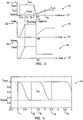
- FIG 2 a typical embodiment of a single-phase induction motor 1 is shown in a schematic drawing.
- the single-phase induction motor 1 comprises a rotor 2 that is rotatably arranged inside the housing of the single-phase induction motor 1.
- the rotation of the rotor 2 (which is indicated by the bent arrow inside the rotor 2) is caused by a rotating magnetic field that is generated by the main winding 3 in combination with an auxiliary winding 4.
- Both the main winding 3 as well as the auxiliary winding 4 are forming the main part of the stator of the single-phase induction motor 1.
- the single-phase induction motor 1 comprises only two electric wires 5, 6 for its power supply
- a special device has to be introduced for generating a phase shift between the main winding 3 and the auxiliary winding 4, thus enabling the generation of a rotating magnetic field.
- This special device is typically realised with a capacitor 7 - as it is done in the present example, as shown in figure 2 .
- the capacity of the capacitor 7 is chosen in a way that the phase shift between main winding 3 and auxiliary winding 4 is sufficiently shifted apart from each other, in particular when the single-phase induction motor 1 is started from a halted position.
- the single-phase induction motor 1 is used as part of an arrangement 8, comprising the single-phase induction motor 1, a mechanical load 9 and a controller unit 10.
- the mechanical load is a pump 9.
- the pump 9 can be used for pumping water out of a well or out of a storage tank, for example. However, different types of mechanical loads can be equally employed.
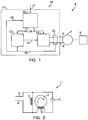
- controller unit 10 for the single-phase induction motor 1 is depicted.
- the controller unit 10 consists of several subunits 12, 13, 14, 15 that are arranged in a common housing 11 (this is indicated by a dashed line in figure 1 ).
- a dashed line in figure 1 it is also possible to provide separate housings for at least some of the subunits 12, 13, 14, 15 of the controller unit 10 and/or to arrange at least some of the subunits 12, 13, 14, 15 with a certain separation from each other.
- the electric connection between the controller unit 10 and the single-phase induction motor 1 is made by only two electric wires 5, 6.
- a single-phase induction motor 1 can be used for replacing a previously used constant speed electric motor in an already existing machinery, for example. In such a case, this replacement would introduce the possibility to drive the pump 9 at different speeds, which is obviously advantageous.
- the controller unit 10 essentially four subunits 12, 13, 14, 15 are depicted: the electronic controller 12, the electric current controller 13, the inverter 14 and an electric current sensor 15.
- the different subunits are interconnected by electric signal lines 16, where appropriate.
- the signal lines 16 can be (in part) of an analogue type and/or (in part) of a digital type. Of course, it is also possible that at least some of the signal lines 16 are designed as a common data bus or the like.
- the electronic controller 12 performs the major controlling task.
- the electronic controller 12 is designed as a single printed board electronic computer unit.
- the electronic controller comprises several interfaces for receiving necessary data as well as for transmitting control signals.
- the electronic controller 12 comprises an input line 17 through which command signals and the like can be inputted (and presumably status signals or the like can be outputted).
- the electronic controller 12 is programmed in a way to perform the start-up cycles, as shown in figure 3 and figure 4 . It can be programmed in a way that it can perform only one type of start-up cycle. Also, it is possible that the electronic controller 12 is able to perform both (or other and/or additional start-up methods), as requested by the user through input line 17.
- a first output signal is transmitted via one of the signal lines 16 to the electric current controller 13.
- Electric current controller 13 compares the target value (as set forth by the electronic controller 12) with an actual value (as measured by the electric current sensors 15). Based on this comparison, an output signal is generated that is transmitted to the inverter 14 through a signal line 16.
- the inverter 14 not only receives a signal from the electric current controller 13, but also directly from the electronic controller 12. Essentially, the electronic controller 12 determines the frequency to be outputted by the inverter 14, while the signal, received from the electric current controller 13 essentially determines the voltage of the output signal and/or the duty cycle of the output signal.
- the output signal of the inverter 14 forms the electric power that is transmitted through the electric cables 5, 6 to the single-phase induction motor 1.
- the amplifiers are included in the inverter 14. However, it is also possible to provide at least some of the amplifiers as separate components.
- the actual electric current through the electric wires 5, 6 is measured by the electronic current sensor 15 and fed back to the electric current controller 13. Furthermore, the measured value is transmitted to the electronic controller 12 itself. This way, the electronic controller 12 is able to determine whether the start-up of the single-phase induction motor 1 has been successful, for example.
- FIG 3 a first possible embodiment for a start-up sequence for starting a single-phase induction motor 1 is shown.
- the frequency graph 18 the voltage graph 19 and the electric current graph 20.
- the evolving time is plotted, while on the ordinate 22 the value of the respective parameter is shown (i.e. frequency, voltage and current).
- the start-up sequence starts by setting f ref to f start .
- f ref denotes the reference value of the frequency, as requested by the electronic controller 12.
- the frequency f ref is set to be twice the normal operating frequency f run of the single-phase induction motor 1.
- the electronic controller 12 demands the electric current controller 13 to ramp up the electric current I to the maximum allowed electric current I max .
- the electric current controller 13 will slowly ramp up the voltage U control for increasing the electric current I to the single-phase induction motor 1.
- a further increase of the electric current is inhibited by limiting the driving voltage U control .
- the rotor 2 of the single-phase induction motor 1 will start to rotate, which can be seen in the frequency graph 18.
- the actual rotating frequency f rotor of the rotor 2 of the single-phase induction motor 1 is plotted.
- the torque that can be produced by the single-phase induction motor 1 is relatively high, so that the single-phase induction motor 1 can be started even with the mechanical load (i.e. the pump 9) connected to the single-phase induction motor 1.
- the actual rotating frequency f rotor that can be achieved by the rotor 2 is lower than the normal rotating frequency when the single-phase induction motor 1 is driven with the nominal running frequency f run .
- the frequency will be ramped down to the "catching frequency" f catch .
- This value is chosen to be close to the rotor frequency f rotor that the single-phase induction motor 1 will achieve during the initial start-up phase.
- the rotor 2 of the single-phase induction motor 1 will be caught at capture time t 4 .
- the rotor 2 begins to follow the frequency of the driving electric current. This can be detected by a significant decrease of the current I, drawn by the single-phase induction motor 1 (and measured by the electric current sensor 15). This behaviour can be seen in the current graph 20 of figure 3 .
- the small peak that can be seen in the voltage graph 19 around t 4 is an artefact of the controlling method.
- the start-up sequence continues with a "normal" start-up sequence according to the state of the art, where the frequency f is slowly ramped up from f catch to the normal running frequency f run at which the single-phase induction motor 1 is driven during normal operation.
- this ramp-up can be done with a constant ratio of U/f.
- the reference value of the frequency f ref is finally reaching the normal operating frequency f run .
- the rotor 2 of the single-phase induction motor 1 follows with a slight delay. As it is normal for induction motors, the rotor 2 shows a slight slip as compared to the driving frequency. This behaviour is due to the design of the single-phase induction motor 1 and is normal.
- f run 30 Hz
- f catch 15 Hz
- FIG 4 a modification of the embodiment of a start-up method for a single-phase induction motor 1, as shown in figure 3 , is shown.
- the reference frequency f ref is set to f start (for example 60 Hz).
- the controller unit 10 starts to lower the reference frequency f ref down to the catch-up frequency f catch .
- an S-shaped ramp is chosen.
- different shapes of ramps can be chosen as well.
- the catch-up frequency f catch of the single-phase induction motor 1 is reached by the reference frequency f ref . Now, it is checked whether the single-phase induction motor 1 has been started (and reached a sufficiently high turning speed). If this start-up has been verified, the initial start-up interval ends and a "normal" ramp-up of the frequency is initialised (see time interval t 4 to t 5 in figure 3 ).
- a second start-up interval is initiated at t 2 .
- the reference frequency f ref set by the electronic controller 12 is again set to the start-up frequency f start .
- this start-up frequency f start is held for a certain time span, in the presently shown example 0.5 seconds.
- the reference frequency f ref is once again lowered to catch-up frequency f catch .
- this catch-up frequency has been reached at t 4 . It is once again checked, whether the single-phase induction motor 1 has actually been started.
- the "normal" ramp-up scheme according to the time interval between t 4 and t 5 in figure 3 is initiated.
- This start-up scheme is continued, until a stop condition is met.
- This stop condition can be derived from external parameters (for example a temperature sensor in the single-phase induction motor 1). Also, internal parameters can be used, for example a timeout condition or a minimum current I stop , where the start-up cycle stops if the measured current is below said value of I stop .
- the actual current can be determined by the (internal) electric current sensor 15.
- stop conditions can also be applied to the embodiment, as shown in figure 3 .
Landscapes
- Engineering & Computer Science (AREA)
- Power Engineering (AREA)
- Control Of Ac Motors In General (AREA)
- Motor And Converter Starters (AREA)
Description
- The invention relates to a method for starting an electric motor, comprising two electric supply conductors for driving said electric motor at least in part and/or at least at times, wherein during a start-up interval of the start-up cycle for starting said electric motor, the frequency of the electric current for driving said electric motor is set to at least one frequency and later to the operating frequency of said electric motor. The invention further relates to a controller unit for an electric motor. Finally, the invention relates to an electric motor device, in particular to a single-phase induction motor device.
- Electric motors as such are well known in the state of the art and used for converting electric energy to mechanical energy. Depending on the situation and requirements of a certain task, different types of electric motors are used.
- One particular requirement often occurring is the possibility to drive the electric motor at variable speeds (rotational speeds). Another requirement is a long lifetime and a simple construction of the electric motor. Both requirements are useful in reducing initial cost as well as the cost for the overall lifetime.
- So-called induction motors are widely used for achieving said requirements. In principle, induction motors have a rotor in form of a cage, wherein the electric conductors within the cage are always short-circuited. The movement of the rotor is induced by applying a rotating magnetic field by means of the stator. For this purpose, usually a multiphase alternating electric current - a so-called rotating electric current - is applied to the different electric coils within the stator. Each phase of the electric current is connected to one of different groups of electric coils in the stator. The different groups of electric coils as well as the electric phases are connected and arranged in a way that a rotating magnetic field is created.
- Depending on the rotation speed of the rotating magnetic field, the rotor of the electric motor will run at different speeds. The rotation speed of the rotor will be approximately the same as the rotation speed of the magnetic field, generated by the stator. Nevertheless, a small slip will occur, resulting in a slightly reduced rotation speed of the rotor, as compared to the rotating speed of the magnetic field.
- For achieving different rotation speeds of the induction motor, it is necessary to provide the electric motor with an appropriately phase shifted rotating electric current of variable frequency. Such a rotating current can nowadays be provided easily and relatively inexpensively by using electric inverters.
- However, sometimes there is a requirement that only two supply lines for supplying the electric motor with electric energy are desired. This requirement occurs frequently, when existing machinery is to be upgraded. Here, sometimes the requirement occurs that a standard, two-phase electric motor (presumably with a fixed rotation speed) is to be replaced by a variable electric motor. In such a situation, providing an additional electric conductor is usually too expensive and/or problematic or not possible at all.
- In such a situation, so-called two-phase induction motors can be used. To be able to produce a rotating magnetic field out of a two-phase electric current, usually two separate groups of electric coils (so-called windings) are used, namely the main winding and the auxiliary winding. To generate a phase shift between the two windings, an electric component is needed that shifts the phase of (part of) the electric current. Usually, capacitors are used for this task. This way, by an appropriate assembly of the main winding and the auxiliary winding on the stator, a rotating magnetic field can be produced, so that the motor can be started from a halted state.
- A big disadvantage of single-phase induction motors is that during the start-up phase (in particular at zero or very low rotating speeds) the electric motor has a very low impedance and consequently an extremely high current is drawn, unless special precautions are made. According to the state of the art, safety resistors are frequently introduced in series to the electric windings of the electric motor during the start-up phase. This way, overheating effects and a too high load on the electric source can be avoided.
- Nevertheless, yet another problem still persists. Since the maximum generated torque is a function of both the electric current and the rotor speed, the initial torque is comparatively low. Hence, the safety resistors are not allowed to be too restrictive. Normally, a current that is about five times larger than the nominal current of the electric motor is provided for initially supplying the electric motor, so that a sufficiently high torque for a fast and reliable start of the electric motor is achieved. This, however, necessitates constructing many parts of the electric motor larger than it is necessary for nominal operation. This, of course, increases the weight and the cost for such an electric motor.
- An example for such a multi-phase induction motor and a preferred method for starting said motor is disclosed in
U.S. Pat. No. 4,999,560 A1 . However, the technical system described in said document is strictly limited to multi-phase electric motors. Furthermore, additional sensors are needed for verifying the successful start-up of the electric motor. - Hence, there is still a need for an electric motor, in particular a two-phase induction motor that has less weight and can be started more reliable.
-
US 2004/0067050 describes a motor control system having a start-up process in which the frequency output of the input is driven above the line frequency during start-up. -
US 4,999,560 describes an electric motor system in which, during start-up, the output frequency of the inverter is increased instantaneously so that the motor produces a torque larger than the load starting torque when the motor is started. - Therefore, the object of the invention is to provide for an improved electric motor.
- The present invention solves this object.
- It is suggested to perform a method for starting an electric motor, comprising two electric supply conductors for driving said electric motor at least in part and/or at least at times, wherein during start-up interval of the start-up cycle for starting said electric motor the frequency of the electric current for driving said electric motor is set to at least one frequency and later to the operating frequency of said electric motor in a way that at least one of said frequencies during the start-up interval and/or during the start-up cycle is at least in part and/or at least at times higher than said operating frequency, wherein the success of the start-up cycle is checked by measuring the electric current consumed by said electric motor and determining whether a significant decrease in the current drawn by the motor occurs. The operating frequency of the electric motor can be (at least in part and/or at least at times) determined by the design of the electric motor. For example, the following design parameters can have (at least a partial) influence on the operating frequency of the electric motor: the electric supply frequency (which is usually 50 Hz or 60 Hz; this way it is possible to bypass a frequency converter during elongated periods of time, i.e. during times when the electric motor is operated at standard operating speed); the long-term mechanical speed limit of the electric motor (which can be influenced by mechanical forces, thermal effects, energy supply limitations, design parameters and/or the like); requirements by the load that is driven by the electric motor; vibration restrictions (in particular of the surroundings in which the electric motor is used); power requirements by the load of the electric motor; and/or other limits and/or requirements. Of course, it is also possible to use any otherwise required and/or desired and/or given rotational speed of the electric motor for determining the operating frequency of the electric motor. By the wording "start-up interval", usually a time interval is denoted during which a singular start-up effort of the electric motor is made. The start-up effort is usually performed from a shut-down state (for example a halted state) to an operational state, wherein it is not necessarily guaranteed that the operational state will be achieved. Furthermore, the operational state does not necessarily has to be a "fully developed" operational state, wherein the speed of the electric motor has essentially reached the desired operating speed of the electric motor. By the wording "start-up cycle" usually a cycle is meant, wherein the electric motor is positively brought from a shut-down state (for example a halted state) to an operational state, and wherein the accomplishment of the operational state is confirmed. In the majority of start-up efforts, the start-up interval and the start-up cycle will be essentially equivalent to each other. However, in a certain percentage of the cases, the start-up cycle might comprise two or even more start-up intervals. In special cases, it is also possible that a start-up interval might extend over two or more start-up cycles. By electric supply conductors, essentially every means of transmitting electric energy is encompassed, wherein the respective conductors are usually designed and arranged in a way that the consumption of electric energy can be at least at times and/or at least in part be fulfilled by said electric conductors. Preferably, the electric motor will comprise only two electric supply conductors (wherein this is to be understood in a logical way, so that a single electric supply conductor can be designed as two parallel wires or the like). Of course, this does not exclude the existence of additional electric conductors, which might be used for transmitting control signals, measurement data, electric supply for other consumers or the like. The electric current can be provided by essentially every means. In particular, it is possible that the electric current can be provided at various frequencies, preferably at frequencies taken from a essentially continuous frequency spectra (even more preferred over a relatively wide range of up to 50 Hz, 75 Hz, 100 Hz, 200 Hz, 500 Hz, 1 kHz, 2 kHz, 5 kHz, 10 kHz, 15 kHz and/or 20 kHz). However, it is also possible that the electric current is limited to a relatively small number of different, distinct frequencies. Hence, it might be possible that only two, three, four, five, six, seven, eight, nine or ten different, distinct frequencies are used. Using a comparatively high frequency during the initial start-up process, it is possible to reduce the amount of the electric current, flowing through (parts of) the electric motor. This is, because usually the impedance is rising with frequency, so that the resulting current will be lower at higher frequencies. This effect is particularly useful during a start-up interval and/or a start-up cycle, particularly when the electric motor is still in a stopped state or is turning only very slowly.
- Preferably the method is performed in a way, wherein said electric motor is at least in part and/or at least at times operated as a single-phase induction motor, wherein said single-phase induction motor preferably comprises at least one main winding and/or at least one auxiliary winding and/or at least one capacitor device. Using such a design, the method can be performed with a very small number of electric conductors and/or with a minimum amount of adaptions (in particular when replacing single-phase induction motors and/or fixed speed electric motors) in most cases. As an example, if a machine, in which an electric motor that is supplied with two electric wires is used, has to be upgraded to a variable speed machinery, such a two-phase induction motor can usually be easily used as a drop-in solution for the previous electric motor. Usually, the controlling device and/or the electric supply devices (for example a frequency inverter or the like) has to be placed apart from the two-phase induction motor in such cases. This, however, is normally no problem when using the present invention and can be easily accomplished without modifying the existing machinery in an inconvenient way. By using a design, wherein the single-phase induction motor comprises at least one main winding and/or at least one auxiliary winding and/or at least one capacitor device, it is usually possible to start the respective electric motor on its own, i.e. without using a separate mechanical start-up source or the like.
- Further, it is suggested that during said start-up interval and/or during said start-up cycle the frequencies are at least in part and/or at least at times changed quickly, preferably changed essentially instantaneously, in particular to a first frequency, being higher than said operating frequency. This way, the length of the complete start-up interval and/or of the complete start-up cycle can usually be shortened, sometimes even considerably. Furthermore, a regime, wherein relatively high electric currents are flowing through the electric motor (or parts of it) can usually be avoided by this method. This is particular true for the low frequency region when the electric motor is still stopped or at a very low rotational speed.
- Alternatively or additionally it is also possible to perform the method in a way that during said start-up interval and/or during said start-up cycle the frequency is at least in part and/or at least at times changed slowly, in particular changed linearly, S-shaped like and/or spline-like, in particular from a first frequency, being higher than said operating frequency to the operating frequency and/or to a catch-up frequency of said electric motor. Using such a slowly changing regime, it is usually easier (or even possible at all) to perform additional tasks, like performing some measurements. The measurements can be used for verifying whether the rotation of the electric motor has been started, as an example. This measurement can be either performed directly (for example by using a sensor for detecting a rotation of the electric motor) or indirectly (for example by using certain effects of the electric motor on the electric current that is driving the electric motor). Of course, different sensors and/or effects can be used additionally and/or alternatively. The catch-up frequency is usually lower than the operating frequency of the electric motor. Usually, catch-up frequency is of about the same order (or even essentially identical) to the actual motor speed of the electric motor. After the catch-up frequency is reached, it is possible to continue with a start-up process, where the electric motor is further accelerated to its operating frequency with standard U/f- methods (or other suitable methods).
- Furthermore it is suggested, to perform the method in a way that at least said first frequency is approximately twice the operating frequency of the electric motor and/or is chosen so that the electric motor essentially yields an increased, preferably a maximum output torque. Having an increased, preferably high, even more preferred maximum output torque of the induction motor, a start-up of the electric motor will be much more likely as compared to a case, where only limited torque is present (for example like in an electric motor that is started with standard operating frequency). Furthermore, the length of the start-up interval and/or the length of the start-up cycle can usually be reduced, sometimes even considerably. First experiments have shown that choosing the first frequency to be about twice as high as the usual operating frequency of the electric motors usually provides a very good and efficient start-up procedure with relatively low (additional) effort. In particular, the electric current flowing through the electric motor can usually be limited to an acceptable level. However, it is also possible to even better adapt the ratio of the first frequency versus the operating frequency of the electric motor even better. It is even possible to set the first frequency in a way that resonance effects of the electric motor can be used (or equivalently to design the electric motor in a way that resonance effects occur, if the first frequency, being determined in a different way, is applied). In particular, the resonance effect can be the resonance of an oscillating circuit (more particularly of the LC-circuit, being formed by the capacitor and the auxiliary winding and/or the main winding). This way, a particularly advantageous start-up behaviour can be achieved.
- Furthermore it is suggested to perform the method in a way that said electric motors is driven at least in part and/or at least at times in a current limiting mode, preferably in a maximum tolerable current limiting mode. This way, the maximum design limit of the electric motor and/or of the electric current supplying components can be used for a quick and/or reliable start-up of the electric motor. Both a quick and reliable start-up is advantageous, of course. It has to be noted that usually the electric and electronic components that are necessary for performing the "basic" start-up method (and hence are already present) will normally be sufficient to perform this preferred embodiment of the method. Of course, it might be necessary to include some additional components to (better) perform this suggested embodiment of the method. However, the additional equipment be can usually limited to a comparatively low level. It has to be noted that the allowed current in a current limiting mode cannot only refer to a current limit, as set forth by the electric motor, but additionally and/or alternatively to a current limit, set forth by other components, like the electric supply unit, the frequency converters (in particular the power transistors)or the like. Using such a current limiting mode can have the effect that the voltage and the frequency (and presumably even more parameters) can be optimised on their own (i.e. more or less independent from other parameters). This usually yields operational advantages. In particular, this will usually result in advantages over present algorithms in which U/f is fixed.
- An even more preferred embodiment of the method can be achieved, if during the start-up interval and/or the start-up cycle the frequency is at least in part and/or at least at times lowered to essentially the actual motor rotation speed and/or to a frequency, being lower than the operating frequency of the electric motor. Using this embodiment, it is usually possible to positively verify, whether the start-up of the electric motor has actually taken place. First experiments have shown, that if the frequency is lowered (particularly to a frequency being approximately the same as the actual rotation frequency of the electric motor), the electric current through the electric motor drops significantly. At or near the actual rotating frequency of the electric motor, usually even a local minimum of the electric current can be observed, which can be used particularly well for verifying purposes (or other purposes). This frequency can be essentially identical to the previously mentioned catch-up frequency. Preferably, the method is performed in a way that another start-up cycle and/or another start-up interval is initiated if the present start-up cycle and/or the present start-up interval was not successful.
- If the method is performed in a way that the success of the start-up cycle and/or the start-up interval is checked, in particular by measuring the electric current, consumed by said electric motor, a further preferred embodiment of the invention can be achieved. If this check yields an affirmative output (i.e. the electric motor has been positively started), this information can be used to end the start-up cycle and/or the start-up interval. This information can also be used to initiate a "finishing cycle", for example to further accelerate the electric motor from a catch-up speed to a standard operating speed. Furthermore, this information can be used for being transmitted to other controlling units and/or to an operator of the machinery. If, on the other hand, the check yields a negative result (i.e., the electric motor has not yet been started), this information can be used for initiating another start-up interval and/or for initiating another start-up cycle, for transmitting an error signal flag and/or to transmit the information to an operator. Additionally and/or alternatively this information can be used to shut down the complete machinery if a certain number of start-up cycles and/or start-up intervals have been performed without success. This is because the latter case is usually a good indication that something is wrong. For example, a mechanical block could be present and continuous effort to start the electric motor might result in damaging the machinery. Of course, also time-out condition can be used for initiating such a shutdown.
- Additionally and/or alternatively another preferred embodiment of the method can be achieved if the frequencies used and/or the voltages used and/or the time intervals used and/or the ramp times used during the start-up cycle and/or during the start-up interval are varied, in particular between different start-up cycles and/or different start-up intervals. This way, you can have a particular fast start-up process on the average. As an example, the first start-up interval can be chosen to be very short with the (adverse) effect that only in 90% of the cases the electric motor is actually started. Now, if the electric motor was not started, a longer, second start-up interval is initiated, where in essentially all cases the electric motor is started. This, of course takes more time, say four times as much time as the first start-up interval needs. However, on the average, the overall start-up time is lower as compared to a case, were in all cases the longer "safe" length of the start-up interval would have been chosen.
- Furthermore, a controller unit for an electric motor, preferably a controller unit comprising at least one frequency converter is suggested, wherein said controller unit is designed and arranged in a way that it performs at least in part and/or at least at times a method according to the previous description. Such a controller unit will show the previously described advantages and characteristics, by analogy. Of course, the controller unit can be modified in the previously described sense. The controller unit is preferably a "stand alone"-unit (where - of course - the electric motor itself can be a part of the stand-alone-unit). This way the controller unit can be sold as a separate unit, in particular for remodelling existing machinery.
- Furthermore, an electric motor device, in particular a single-phase induction motor device is suggested, wherein said electric motor device comprises at least one controller unit of the previously described design and/or wherein said electric motor device is designed and arranged in a way that it performs at least in part and/or at least at times a method according to the previous description. Of course, the electric motor device will show the previously described characteristics and advantages by analogy. Furthermore, said electric motor device can be modified in the previously described sense.
- The present invention and its advantages will become more apparent, when looking at the following description of possible embodiments of the invention, which will be described with reference to the accompanying figures, which are showing:
- Fig. 1:
- a preferred embodiment of a controller for controlling the power supply to a single-phase induction motor in a schematic view ;
- Fig. 2:
- a typical embodiment for a single-phase induction motor in a schematic view;
- Fig. 3:
- a first embodiment of a method for starting a single-phase induction motor;
- Fig. 4:
- a second embodiment of a method for starting a single-phase induction motor.
- In
figure 2 a typical embodiment of a single-phase induction motor 1 is shown in a schematic drawing. The single-phase induction motor 1 comprises arotor 2 that is rotatably arranged inside the housing of the single-phase induction motor 1. The rotation of the rotor 2 (which is indicated by the bent arrow inside the rotor 2) is caused by a rotating magnetic field that is generated by the main winding 3 in combination with an auxiliary winding 4. Both the main winding 3 as well as the auxiliary winding 4 are forming the main part of the stator of the single-phase induction motor 1. Since the single-phase induction motor 1 comprises only twoelectric wires figure 2 . The capacity of the capacitor 7 is chosen in a way that the phase shift between main winding 3 and auxiliary winding 4 is sufficiently shifted apart from each other, in particular when the single-phase induction motor 1 is started from a halted position. - In
figure 1 , the single-phase induction motor 1 is used as part of anarrangement 8, comprising the single-phase induction motor 1, amechanical load 9 and acontroller unit 10. In the present embodiment, the mechanical load is apump 9. Thepump 9 can be used for pumping water out of a well or out of a storage tank, for example. However, different types of mechanical loads can be equally employed. - In
figure 1 on the left side, thecontroller unit 10 for the single-phase induction motor 1 is depicted. Thecontroller unit 10 consists ofseveral subunits figure 1 ). Of course, it is also possible to provide separate housings for at least some of thesubunits controller unit 10 and/or to arrange at least some of thesubunits - As can be seen from
figure 1 , the electric connection between thecontroller unit 10 and the single-phase induction motor 1 is made by only twoelectric wires phase induction motor 1 can be used for replacing a previously used constant speed electric motor in an already existing machinery, for example. In such a case, this replacement would introduce the possibility to drive thepump 9 at different speeds, which is obviously advantageous. - In the presently shown embodiment of the
controller unit 10, essentially foursubunits electronic controller 12, the electriccurrent controller 13, theinverter 14 and an electriccurrent sensor 15. The different subunits are interconnected byelectric signal lines 16, where appropriate. The signal lines 16 can be (in part) of an analogue type and/or (in part) of a digital type. Of course, it is also possible that at least some of thesignal lines 16 are designed as a common data bus or the like. - The
electronic controller 12 performs the major controlling task. In the presently depicted embodiment, theelectronic controller 12 is designed as a single printed board electronic computer unit. The electronic controller comprises several interfaces for receiving necessary data as well as for transmitting control signals. Apart from the already mentionedsignal lines 16, leading to and coming from other components of thecontroller unit 10, theelectronic controller 12 comprises aninput line 17 through which command signals and the like can be inputted (and presumably status signals or the like can be outputted). Theelectronic controller 12 is programmed in a way to perform the start-up cycles, as shown infigure 3 and figure 4 . It can be programmed in a way that it can perform only one type of start-up cycle. Also, it is possible that theelectronic controller 12 is able to perform both (or other and/or additional start-up methods), as requested by the user throughinput line 17. - A first output signal is transmitted via one of the
signal lines 16 to the electriccurrent controller 13. Electriccurrent controller 13 compares the target value (as set forth by the electronic controller 12) with an actual value (as measured by the electric current sensors 15). Based on this comparison, an output signal is generated that is transmitted to theinverter 14 through asignal line 16. - The
inverter 14 not only receives a signal from the electriccurrent controller 13, but also directly from theelectronic controller 12. Essentially, theelectronic controller 12 determines the frequency to be outputted by theinverter 14, while the signal, received from the electriccurrent controller 13 essentially determines the voltage of the output signal and/or the duty cycle of the output signal. The output signal of theinverter 14 forms the electric power that is transmitted through theelectric cables phase induction motor 1. In the presently shown embodiment, the amplifiers are included in theinverter 14. However, it is also possible to provide at least some of the amplifiers as separate components. - The actual electric current through the
electric wires current sensor 15 and fed back to the electriccurrent controller 13. Furthermore, the measured value is transmitted to theelectronic controller 12 itself. This way, theelectronic controller 12 is able to determine whether the start-up of the single-phase induction motor 1 has been successful, for example. - In
figure 3 a first possible embodiment for a start-up sequence for starting a single-phase induction motor 1 is shown. In the figure, altogether three graphs are shown: thefrequency graph 18 thevoltage graph 19 and the electriccurrent graph 20. In each of the graphs, on the abscissa 21 the evolving time is plotted, while on theordinate 22 the value of the respective parameter is shown (i.e. frequency, voltage and current). - At t1 the start-up sequence (the start-up interval) starts by setting fref to fstart. fref denotes the reference value of the frequency, as requested by the
electronic controller 12. In the present example, the frequency fref is set to be twice the normal operating frequency frun of the single-phase induction motor 1. At the same time t1, theelectronic controller 12 demands the electriccurrent controller 13 to ramp up the electric current I to the maximum allowed electric current Imax. To be able to use some feedback by the electriccurrent sensor 15, the electriccurrent controller 13 will slowly ramp up the voltage Ucontrol for increasing the electric current I to the single-phase induction motor 1. As soon as the actual current I through the single-phase induction motor 1 reaches the maximum at t2, a further increase of the electric current is inhibited by limiting the driving voltage Ucontrol. - Parallel to this the
rotor 2 of the single-phase induction motor 1 will start to rotate, which can be seen in thefrequency graph 18. Here, the actual rotating frequency frotor of therotor 2 of the single-phase induction motor 1 is plotted. During this initial phase, starting with t1 (and ending with t3), the torque that can be produced by the single-phase induction motor 1 is relatively high, so that the single-phase induction motor 1 can be started even with the mechanical load (i.e. the pump 9) connected to the single-phase induction motor 1. However, due to the comparatively high frequency fref, the actual rotating frequency frotor that can be achieved by therotor 2 is lower than the normal rotating frequency when the single-phase induction motor 1 is driven with the nominal running frequency frun. - After a set time (which can be chosen with a sufficiently high safety margin, so that the probability of actually starting the single-
phase induction motor 1 is sufficiently high), the frequency will be ramped down to the "catching frequency" fcatch. This value is chosen to be close to the rotor frequency frotor that the single-phase induction motor 1 will achieve during the initial start-up phase. After this ramp-down process, therotor 2 of the single-phase induction motor 1 will be caught at capture time t4. Here, therotor 2 begins to follow the frequency of the driving electric current. This can be detected by a significant decrease of the current I, drawn by the single-phase induction motor 1 (and measured by the electric current sensor 15). This behaviour can be seen in thecurrent graph 20 offigure 3 . The small peak that can be seen in thevoltage graph 19 around t4 is an artefact of the controlling method. - Once the
rotor 2 of the single-phase induction motor has been caught, the start-up sequence continues with a "normal" start-up sequence according to the state of the art, where the frequency f is slowly ramped up from fcatch to the normal running frequency frun at which the single-phase induction motor 1 is driven during normal operation. In particular, this ramp-up can be done with a constant ratio of U/f. - At t5 the reference value of the frequency fref is finally reaching the normal operating frequency frun. The
rotor 2 of the single-phase induction motor 1 follows with a slight delay. As it is normal for induction motors, therotor 2 shows a slight slip as compared to the driving frequency. This behaviour is due to the design of the single-phase induction motor 1 and is normal. - The frequencies in the above described example are set to be frun = 30 Hz, fcatch = 15 Hz and fstart 60 Hz.
- In
figure 4 a modification of the embodiment of a start-up method for a single-phase induction motor 1, as shown infigure 3 , is shown. Here, only the output frequency fref of theelectronic controller 12 is shown for elucidating the method. Initially, at t1, the reference frequency fref is set to fstart (for example 60 Hz). Having reached the starting frequency fstart (where a quite high torque is generated in the single-phase induction motor 1), however, the frequency is not held at this value. Instead, practically instantaneously thecontroller unit 10 starts to lower the reference frequency fref down to the catch-up frequency fcatch. In the embodiment chosen, an S-shaped ramp is chosen. However, different shapes of ramps can be chosen as well. Furthermore, it is of course possible to introduce a short time delay between t1 and the beginning of the first ramp-down process. - At t2 the catch-up frequency fcatch of the single-
phase induction motor 1 is reached by the reference frequency fref. Now, it is checked whether the single-phase induction motor 1 has been started (and reached a sufficiently high turning speed). If this start-up has been verified, the initial start-up interval ends and a "normal" ramp-up of the frequency is initialised (see time interval t4 to t5 infigure 3 ). - If, however, it has been detected that the single-
phase induction motor 1 has not been started (and/or has not acquired a sufficiently high rotating speed), a second start-up interval is initiated at t2. Now, the reference frequency fref, set by theelectronic controller 12 is again set to the start-up frequency fstart. Now, this start-up frequency fstart is held for a certain time span, in the presently shown example 0.5 seconds. At the end of this holding interval, at t3, the reference frequency fref is once again lowered to catch-up frequency fcatch. As soon as this catch-up frequency has been reached at t4, it is once again checked, whether the single-phase induction motor 1 has actually been started. Once again, if the start-up of the single-phase induction motor 1 has been confirmed, the "normal" ramp-up scheme according to the time interval between t4 and t5 infigure 3 is initiated. - If, however the start-up has been not successful again, another start-up interval is started at t4. Now, the starting frequency fstart is held for one second till t5, when the reference frequency fref is once again lowered.
- This start-up scheme is continued, until a stop condition is met. This stop condition can be derived from external parameters (for example a temperature sensor in the single-phase induction motor 1). Also, internal parameters can be used, for example a timeout condition or a minimum current Istop, where the start-up cycle stops if the measured current is below said value of Istop. The actual current can be determined by the (internal) electric
current sensor 15. - It should be mentioned that these stop conditions can also be applied to the embodiment, as shown in
figure 3 .
Claims (12)
- A method for starting an electric motor, comprising two electric supply conductors for driving said electric motor at least in part and/or at least at times, wherein during a start-up interval of the start-up cycle for starting said electric motor, the frequency (fref) of the electric current for driving said electric motor is set to at least one frequency (fstart), and later to the operating frequency (frun) of said electric motor, wherein at least one of said frequencies (fstart) during the start-up interval and/or during the start-up cycle is at least in part and/or at least at times higher than said operating frequency (frun), characterised in that the success of the start-up cycle is checked by measuring the electric current (I) consumed by said electric motor and determining whether a significant decrease in the current drawn by the motor occurs.
- The method according to claim 1, wherein said electric motor is at least in part and/or at least at times operated as a single-phase induction motor, wherein said single-phase induction motor preferably comprises at least one main winding and/or at least one auxiliary winding and/or at least one capacitor device.
- The method according to claim 1 or claim 2, wherein during said start-up interval and/or said start-up cycle the frequency (fref) is at least in part and/or at least at times changed quickly, preferably changed essentially instantaneously, in particular to a first frequency (fstart), being higher than said operating frequency (fref).
- The method according to any preceding claim, wherein during said start-up interval and/or during said start-up cycle the frequency (fref) is at least in part and/or at least at times changed slowly, in particular changed linearly, s-shaped-like and/or spline-like, in particular from a first frequency (fstart), being higher than said operating frequency to the operating frequency (frun) and/or to a catch-up frequency (fcatch) of said electric motor.
- The method according to any preceding claim, wherein at least said first frequency (fstart) is approximately twice the operating frequency (frun) of the electric motor and/or is chosen so that the electric motor essentially yields an increased, preferably a maximum output torque.
- The method according to any preceding claim, wherein said electric motor is driven at least in part and/or at least at times in a current limiting mode, preferably in a maximum tolerable current limiting mode (Imax).
- The method according to any preceding claim, wherein during the start-up interval and/or during the start-up cycle the frequency (fref) is at least in part and/or at least at times lowered to essentially the actual motor rotation speed (frotor) and/or to a frequency, being lower than the operating frequency (frun) of the electric motor.
- The method according to any preceding claim, wherein another start-up interval and/or another start-up cycle is initiated, if the present start-up interval and/or the present start-up cycle was not successful.
- The method according to any preceding claim, wherein the frequencies (f) used and/or the voltages (U) used and/or the time intervals used and/or the ramp times used during the start-up interval and/or during the start-up cycle are varied, in particular between different start-up intervals and/or between different start-up cycles.
- A controller unit for an electric motor having two electric supply conductors for driving said electric motor at least in part and/or at least at times, the controller unit comprising at least one frequency converter, wherein the controller unit is configured such that:during a start-up interval of the start-up cycle for starting said electric motor, the frequency (fref) of the electric current for driving said electric motor is set to at least one frequency (fstart), and later to the operating frequency (frun) of said electric motor, wherein at least one of said frequencies (fstart) during the start-up interval and/or during the start-up cycle is at least in part and/or at least at times higher than said operating frequency (frun); andthe success of the start-up cycle is checked by measuring the electric current (I) consumed by said electric motor and determining whether a significant decrease in the current drawn by the motor occurs.
- An electric motor device comprising at least one controller unit according to claim 10.
- An electric motor device as claimed in claim 11, wherein the electric motor device is a single-phase induction motor device.
Applications Claiming Priority (2)
| Application Number | Priority Date | Filing Date | Title |
|---|---|---|---|
| US12/847,582 US11563389B2 (en) | 2010-07-30 | 2010-07-30 | Method for starting a single-phase induction motor |
| PCT/DK2011/000086 WO2012013189A2 (en) | 2010-07-30 | 2011-07-27 | Method for starting a single-phase induction motor |
Publications (2)
| Publication Number | Publication Date |
|---|---|
| EP2599212A2 EP2599212A2 (en) | 2013-06-05 |
| EP2599212B1 true EP2599212B1 (en) | 2017-05-17 |
Family
ID=44581876
Family Applications (1)
| Application Number | Title | Priority Date | Filing Date |
|---|---|---|---|
| EP11743960.4A Not-in-force EP2599212B1 (en) | 2010-07-30 | 2011-07-27 | Method for starting a single-phase induction motor |
Country Status (6)
| Country | Link |
|---|---|
| US (1) | US11563389B2 (en) |
| EP (1) | EP2599212B1 (en) |
| CN (1) | CN103201942B (en) |
| AU (1) | AU2011285296B2 (en) |
| CA (1) | CA2807058C (en) |
| WO (1) | WO2012013189A2 (en) |
Families Citing this family (4)
| Publication number | Priority date | Publication date | Assignee | Title |
|---|---|---|---|---|
| CN103309368B (en) * | 2013-05-10 | 2015-08-26 | 西安航空动力股份有限公司 | For the driving power frequency setting method of turbine oil pump group test |
| DE102013020904B3 (en) * | 2013-12-16 | 2014-11-20 | Dräger Safety AG & Co. KGaA | Device for monitoring a mass or volume flow of a gas stream |
| CN103701374B (en) * | 2013-12-17 | 2016-04-06 | 上海发电设备成套设计研究院 | A kind of soft-start method of high-voltage frequency conversion and speed-adjusting device |
| USD928010S1 (en) | 2019-06-12 | 2021-08-17 | Marc Balayer | Wristwatch holder with lid and interchangeable ring |
Family Cites Families (35)
| Publication number | Priority date | Publication date | Assignee | Title |
|---|---|---|---|---|
| SU464948A1 (en) | 1973-02-20 | 1975-03-25 | Научно-Исследовательский Институт Автоматики И Электромеханики При Томском Институте Автоматизированных Систем Управления И Радиоэлектроники | Starting method of single-phase asynchronous electric motor |
| US4012679A (en) * | 1974-01-06 | 1977-03-15 | Hitachi, Ltd. | Method and apparatus for controlling the operation of synchronous motor |
| EP0053208B1 (en) * | 1980-11-28 | 1984-11-14 | International Business Machines Corporation | Motor control system for a single phase induction motor |
| US4486700A (en) * | 1983-05-09 | 1984-12-04 | Texas Instruments Incorporated | Universal single phase motor starting control apparatus |
| GB2176667B (en) | 1985-06-11 | 1989-07-05 | Toshiba Kk | Electric motor running system employing a photovoltaic array |
| JPS62129656A (en) * | 1985-11-28 | 1987-06-11 | 株式会社東芝 | Air conditioner |
| US4642543A (en) * | 1985-12-09 | 1987-02-10 | General Electric Company | Starting sequence for reluctance motor drives operating without a shaft position sensor |
| US4833628A (en) * | 1986-10-16 | 1989-05-23 | Square D Company | Up to speed detector for an electric motor using measured values of the current lag; and voltage ramp controller using the up to speed indication |
| US5508905A (en) * | 1992-08-06 | 1996-04-16 | Metropolitan Pump Company | Low distortion variable output power supply |
| US5519337A (en) * | 1993-11-04 | 1996-05-21 | Martin Marietta Energy Systems, Inc. | Motor monitoring method and apparatus using high frequency current components |
| US5828200A (en) * | 1995-11-21 | 1998-10-27 | Phase Iii | Motor control system for variable speed induction motors |
| US5883489A (en) * | 1996-09-27 | 1999-03-16 | General Electric Company | High speed deep well pump for residential use |
| DE19701856A1 (en) * | 1997-01-21 | 1998-07-23 | Wunnibald Kunz | Electronic start-up and operation control for a single-phase synchronous motor |
| US6160372A (en) * | 1997-07-14 | 2000-12-12 | Robertshaw Controls Company | Solid state motor start method and apparatus |
| DE69824925T2 (en) * | 1997-09-17 | 2005-08-25 | Mitsubishi Heavy Industries, Ltd. | Leitschaufelpaar |
| US6025693A (en) * | 1997-10-20 | 2000-02-15 | Smith; Otto J. M. | Motor starter |
| US6150776A (en) * | 1999-05-04 | 2000-11-21 | Metropolitan Industries, Inc. | Variable frequency motor starting system and method |
| US6570778B2 (en) * | 2001-08-30 | 2003-05-27 | Wisconsin Alumni Research Foundation | Adjustable speed drive for single-phase induction motors |
| TWI267818B (en) * | 2001-09-05 | 2006-12-01 | Elantec Semiconductor Inc | A method and apparatus to generate reference voltages for flat panel displays |
| JP3912190B2 (en) * | 2002-05-31 | 2007-05-09 | 松下電器産業株式会社 | Brushless motor drive device and motor using the same |
| US6762629B2 (en) * | 2002-07-26 | 2004-07-13 | Intel Corporation | VCC adaptive dynamically variable frequency clock system for high performance low power microprocessors |
| US6845305B1 (en) * | 2002-09-11 | 2005-01-18 | Ford Motor Company | Engine torque control for a hybrid electric vehicle using estimated engine torque |
| KR20050083692A (en) | 2002-09-13 | 2005-08-26 | 츠다코마 고교 가부시키가이샤 | Control method of induction motor |
| US7272302B2 (en) * | 2002-10-08 | 2007-09-18 | Emerson Electric Co. | PSC motor system for use in HVAC applications with field adjustment and fail-safe capabilities |
| US6801013B2 (en) * | 2002-10-08 | 2004-10-05 | Emerson Electric Co. | PSC motor system for use in HVAC applications |
| US6829565B2 (en) * | 2003-02-14 | 2004-12-07 | Xerox Corporation | Stepper motor automated self-test routine |
| CN1549439A (en) | 2003-05-16 | 2004-11-24 | 富士电机株式会社 | motor drive system |
| US7468595B2 (en) * | 2005-07-26 | 2008-12-23 | Eaton Corporation | System and method of controlling the start-up of an adjustable speed motor drive based sinusoidal output power conditioner |
| US7208909B2 (en) * | 2005-07-29 | 2007-04-24 | Rockwell Automation Technologies, Inc. | Motor protection inhibit circuit |
| JP2008104337A (en) * | 2006-09-21 | 2008-05-01 | Sanyo Electric Co Ltd | Control unit of electromotor for refrigerant compressor |
| US7965052B2 (en) * | 2008-07-22 | 2011-06-21 | Pratt & Whitney Canada Corp. | Motor driving system and method for starting a motor |
| US8386104B2 (en) * | 2009-06-01 | 2013-02-26 | Ford Global Technologies, Llc | System and method for displaying power flow in a hybrid vehicle |
| JP5553564B2 (en) * | 2009-09-18 | 2014-07-16 | キヤノン株式会社 | Vibration type motor control device and imaging device |
| US8760089B2 (en) * | 2009-11-30 | 2014-06-24 | Franklin Electric Company, Inc. | Variable speed drive system |
| US9577556B2 (en) * | 2014-07-30 | 2017-02-21 | Regal Beloit America, Inc. | System and method for starting a motor |
-
2010
- 2010-07-30 US US12/847,582 patent/US11563389B2/en active Active
-
2011
- 2011-07-27 CA CA2807058A patent/CA2807058C/en active Active
- 2011-07-27 CN CN201180037667.3A patent/CN103201942B/en active Active
- 2011-07-27 WO PCT/DK2011/000086 patent/WO2012013189A2/en not_active Ceased
- 2011-07-27 AU AU2011285296A patent/AU2011285296B2/en not_active Ceased
- 2011-07-27 EP EP11743960.4A patent/EP2599212B1/en not_active Not-in-force
Non-Patent Citations (1)
| Title |
|---|
| None * |
Also Published As
| Publication number | Publication date |
|---|---|
| CA2807058C (en) | 2016-09-06 |
| WO2012013189A2 (en) | 2012-02-02 |
| EP2599212A2 (en) | 2013-06-05 |
| US20120025748A1 (en) | 2012-02-02 |
| CA2807058A1 (en) | 2012-02-02 |
| US11563389B2 (en) | 2023-01-24 |
| AU2011285296B2 (en) | 2016-03-03 |
| CN103201942B (en) | 2016-08-24 |
| WO2012013189A3 (en) | 2012-08-09 |
| CN103201942A (en) | 2013-07-10 |
| AU2011285296A1 (en) | 2013-02-21 |
Similar Documents
| Publication | Publication Date | Title |
|---|---|---|
| EP2020745B1 (en) | Engine start system with a regulated permanent magnet machine | |
| US9054615B2 (en) | Method and apparatus for control of a synchronous permanent magnet motor, particularly over a long cable in a well | |
| EP2001121A2 (en) | Engine start system with quadrature AC excitation | |
| JP4012604B2 (en) | Method for controlling the torque of an AC motor | |
| AU2011285296B2 (en) | Method for starting a single-phase induction motor | |
| EP3456972B1 (en) | Method of operating an electric induction motor in the event of a power loss | |
| JP2011520411A (en) | Double feed axial flux induction generator | |
| CN102077459B (en) | Method for controlling rotating electric machine, particularly alternator | |
| CN102694500B (en) | Speed Searching Device for Inverter and Its Induction Motor | |
| KR102485760B1 (en) | An electric system for an electromechanical power transmission chain | |
| CN101627531A (en) | Method and system to start multiple AC motors supplied by a power converter via a common AC bus | |
| JP2007085337A (en) | Vacuum pump device | |
| CN112555148B (en) | Control device for electric oil pump, and electric oil pump | |
| KR102216667B1 (en) | Apparatus and Method for controlling power source abnormality of motor | |
| KR20180101369A (en) | Vacuum pump drive for star-delta conversion | |
| JP2018050399A (en) | Field winding type synchronous motor and control method thereof | |
| JP2004048988A (en) | Switch reluctance machine | |
| JP2024037271A (en) | Power generating system and activation method | |
| JP4822138B2 (en) | Power generation system and operation method thereof | |
| JP2005086906A (en) | Method for starting variable speed generator motor and control device for variable speed generator motor | |
| JPS5918960B2 (en) | Starting circuit of shaft drive generator |
Legal Events
| Date | Code | Title | Description |
|---|---|---|---|
| PUAI | Public reference made under article 153(3) epc to a published international application that has entered the european phase |
Free format text: ORIGINAL CODE: 0009012 |
|
| 17P | Request for examination filed |
Effective date: 20130117 |
|
| AK | Designated contracting states |
Kind code of ref document: A2 Designated state(s): AL AT BE BG CH CY CZ DE DK EE ES FI FR GB GR HR HU IE IS IT LI LT LU LV MC MK MT NL NO PL PT RO RS SE SI SK SM TR |
|
| DAX | Request for extension of the european patent (deleted) | ||
| GRAP | Despatch of communication of intention to grant a patent |
Free format text: ORIGINAL CODE: EPIDOSNIGR1 |
|
| INTG | Intention to grant announced |
Effective date: 20170217 |
|
| GRAS | Grant fee paid |
Free format text: ORIGINAL CODE: EPIDOSNIGR3 |
|
| GRAA | (expected) grant |
Free format text: ORIGINAL CODE: 0009210 |
|
| AK | Designated contracting states |
Kind code of ref document: B1 Designated state(s): AL AT BE BG CH CY CZ DE DK EE ES FI FR GB GR HR HU IE IS IT LI LT LU LV MC MK MT NL NO PL PT RO RS SE SI SK SM TR |
|
| REG | Reference to a national code |
Ref country code: GB Ref legal event code: FG4D |
|
| REG | Reference to a national code |
Ref country code: CH Ref legal event code: EP |
|
| REG | Reference to a national code |
Ref country code: IE Ref legal event code: FG4D |
|
| REG | Reference to a national code |
Ref country code: AT Ref legal event code: REF Ref document number: 895283 Country of ref document: AT Kind code of ref document: T Effective date: 20170615 |
|
| REG | Reference to a national code |
Ref country code: DE Ref legal event code: R096 Ref document number: 602011038044 Country of ref document: DE |
|
| REG | Reference to a national code |
Ref country code: NL Ref legal event code: MP Effective date: 20170517 |
|
| REG | Reference to a national code |
Ref country code: LT Ref legal event code: MG4D |
|
| REG | Reference to a national code |
Ref country code: AT Ref legal event code: MK05 Ref document number: 895283 Country of ref document: AT Kind code of ref document: T Effective date: 20170517 |
|
| PG25 | Lapsed in a contracting state [announced via postgrant information from national office to epo] |
Ref country code: ES Free format text: LAPSE BECAUSE OF FAILURE TO SUBMIT A TRANSLATION OF THE DESCRIPTION OR TO PAY THE FEE WITHIN THE PRESCRIBED TIME-LIMIT Effective date: 20170517 Ref country code: HR Free format text: LAPSE BECAUSE OF FAILURE TO SUBMIT A TRANSLATION OF THE DESCRIPTION OR TO PAY THE FEE WITHIN THE PRESCRIBED TIME-LIMIT Effective date: 20170517 Ref country code: AT Free format text: LAPSE BECAUSE OF FAILURE TO SUBMIT A TRANSLATION OF THE DESCRIPTION OR TO PAY THE FEE WITHIN THE PRESCRIBED TIME-LIMIT Effective date: 20170517 Ref country code: GR Free format text: LAPSE BECAUSE OF FAILURE TO SUBMIT A TRANSLATION OF THE DESCRIPTION OR TO PAY THE FEE WITHIN THE PRESCRIBED TIME-LIMIT Effective date: 20170818 Ref country code: NO Free format text: LAPSE BECAUSE OF FAILURE TO SUBMIT A TRANSLATION OF THE DESCRIPTION OR TO PAY THE FEE WITHIN THE PRESCRIBED TIME-LIMIT Effective date: 20170817 Ref country code: LT Free format text: LAPSE BECAUSE OF FAILURE TO SUBMIT A TRANSLATION OF THE DESCRIPTION OR TO PAY THE FEE WITHIN THE PRESCRIBED TIME-LIMIT Effective date: 20170517 Ref country code: FI Free format text: LAPSE BECAUSE OF FAILURE TO SUBMIT A TRANSLATION OF THE DESCRIPTION OR TO PAY THE FEE WITHIN THE PRESCRIBED TIME-LIMIT Effective date: 20170517 |
|
| PG25 | Lapsed in a contracting state [announced via postgrant information from national office to epo] |
Ref country code: RS Free format text: LAPSE BECAUSE OF FAILURE TO SUBMIT A TRANSLATION OF THE DESCRIPTION OR TO PAY THE FEE WITHIN THE PRESCRIBED TIME-LIMIT Effective date: 20170517 Ref country code: NL Free format text: LAPSE BECAUSE OF FAILURE TO SUBMIT A TRANSLATION OF THE DESCRIPTION OR TO PAY THE FEE WITHIN THE PRESCRIBED TIME-LIMIT Effective date: 20170517 Ref country code: PL Free format text: LAPSE BECAUSE OF FAILURE TO SUBMIT A TRANSLATION OF THE DESCRIPTION OR TO PAY THE FEE WITHIN THE PRESCRIBED TIME-LIMIT Effective date: 20170517 Ref country code: LV Free format text: LAPSE BECAUSE OF FAILURE TO SUBMIT A TRANSLATION OF THE DESCRIPTION OR TO PAY THE FEE WITHIN THE PRESCRIBED TIME-LIMIT Effective date: 20170517 Ref country code: BG Free format text: LAPSE BECAUSE OF FAILURE TO SUBMIT A TRANSLATION OF THE DESCRIPTION OR TO PAY THE FEE WITHIN THE PRESCRIBED TIME-LIMIT Effective date: 20170817 Ref country code: SE Free format text: LAPSE BECAUSE OF FAILURE TO SUBMIT A TRANSLATION OF THE DESCRIPTION OR TO PAY THE FEE WITHIN THE PRESCRIBED TIME-LIMIT Effective date: 20170517 Ref country code: IS Free format text: LAPSE BECAUSE OF FAILURE TO SUBMIT A TRANSLATION OF THE DESCRIPTION OR TO PAY THE FEE WITHIN THE PRESCRIBED TIME-LIMIT Effective date: 20170917 |
|
| PG25 | Lapsed in a contracting state [announced via postgrant information from national office to epo] |
Ref country code: RO Free format text: LAPSE BECAUSE OF FAILURE TO SUBMIT A TRANSLATION OF THE DESCRIPTION OR TO PAY THE FEE WITHIN THE PRESCRIBED TIME-LIMIT Effective date: 20170517 Ref country code: SK Free format text: LAPSE BECAUSE OF FAILURE TO SUBMIT A TRANSLATION OF THE DESCRIPTION OR TO PAY THE FEE WITHIN THE PRESCRIBED TIME-LIMIT Effective date: 20170517 Ref country code: EE Free format text: LAPSE BECAUSE OF FAILURE TO SUBMIT A TRANSLATION OF THE DESCRIPTION OR TO PAY THE FEE WITHIN THE PRESCRIBED TIME-LIMIT Effective date: 20170517 Ref country code: DK Free format text: LAPSE BECAUSE OF FAILURE TO SUBMIT A TRANSLATION OF THE DESCRIPTION OR TO PAY THE FEE WITHIN THE PRESCRIBED TIME-LIMIT Effective date: 20170517 Ref country code: CZ Free format text: LAPSE BECAUSE OF FAILURE TO SUBMIT A TRANSLATION OF THE DESCRIPTION OR TO PAY THE FEE WITHIN THE PRESCRIBED TIME-LIMIT Effective date: 20170517 |
|
| REG | Reference to a national code |
Ref country code: DE Ref legal event code: R097 Ref document number: 602011038044 Country of ref document: DE |
|
| PG25 | Lapsed in a contracting state [announced via postgrant information from national office to epo] |
Ref country code: IT Free format text: LAPSE BECAUSE OF FAILURE TO SUBMIT A TRANSLATION OF THE DESCRIPTION OR TO PAY THE FEE WITHIN THE PRESCRIBED TIME-LIMIT Effective date: 20170517 Ref country code: SM Free format text: LAPSE BECAUSE OF FAILURE TO SUBMIT A TRANSLATION OF THE DESCRIPTION OR TO PAY THE FEE WITHIN THE PRESCRIBED TIME-LIMIT Effective date: 20170517 |
|
| REG | Reference to a national code |
Ref country code: CH Ref legal event code: PL |
|
| PLBE | No opposition filed within time limit |
Free format text: ORIGINAL CODE: 0009261 |
|
| STAA | Information on the status of an ep patent application or granted ep patent |
Free format text: STATUS: NO OPPOSITION FILED WITHIN TIME LIMIT |
|
| REG | Reference to a national code |
Ref country code: IE Ref legal event code: MM4A |
|
| 26N | No opposition filed |
Effective date: 20180220 |
|
| GBPC | Gb: european patent ceased through non-payment of renewal fee |
Effective date: 20170817 |
|
| REG | Reference to a national code |
Ref country code: FR Ref legal event code: ST Effective date: 20180330 |
|
| PG25 | Lapsed in a contracting state [announced via postgrant information from national office to epo] |
Ref country code: IE Free format text: LAPSE BECAUSE OF NON-PAYMENT OF DUE FEES Effective date: 20170727 Ref country code: CH Free format text: LAPSE BECAUSE OF NON-PAYMENT OF DUE FEES Effective date: 20170731 Ref country code: LI Free format text: LAPSE BECAUSE OF NON-PAYMENT OF DUE FEES Effective date: 20170731 |
|
| PG25 | Lapsed in a contracting state [announced via postgrant information from national office to epo] |
Ref country code: SI Free format text: LAPSE BECAUSE OF FAILURE TO SUBMIT A TRANSLATION OF THE DESCRIPTION OR TO PAY THE FEE WITHIN THE PRESCRIBED TIME-LIMIT Effective date: 20170517 Ref country code: FR Free format text: LAPSE BECAUSE OF NON-PAYMENT OF DUE FEES Effective date: 20170731 |
|
| REG | Reference to a national code |
Ref country code: BE Ref legal event code: MM Effective date: 20170731 |
|
| PG25 | Lapsed in a contracting state [announced via postgrant information from national office to epo] |
Ref country code: LU Free format text: LAPSE BECAUSE OF NON-PAYMENT OF DUE FEES Effective date: 20170727 |
|
| PG25 | Lapsed in a contracting state [announced via postgrant information from national office to epo] |
Ref country code: GB Free format text: LAPSE BECAUSE OF NON-PAYMENT OF DUE FEES Effective date: 20170817 |
|
| PG25 | Lapsed in a contracting state [announced via postgrant information from national office to epo] |
Ref country code: BE Free format text: LAPSE BECAUSE OF NON-PAYMENT OF DUE FEES Effective date: 20170731 |
|
| PG25 | Lapsed in a contracting state [announced via postgrant information from national office to epo] |
Ref country code: MT Free format text: LAPSE BECAUSE OF NON-PAYMENT OF DUE FEES Effective date: 20170727 |
|
| PG25 | Lapsed in a contracting state [announced via postgrant information from national office to epo] |
Ref country code: MC Free format text: LAPSE BECAUSE OF FAILURE TO SUBMIT A TRANSLATION OF THE DESCRIPTION OR TO PAY THE FEE WITHIN THE PRESCRIBED TIME-LIMIT Effective date: 20170517 Ref country code: HU Free format text: LAPSE BECAUSE OF FAILURE TO SUBMIT A TRANSLATION OF THE DESCRIPTION OR TO PAY THE FEE WITHIN THE PRESCRIBED TIME-LIMIT; INVALID AB INITIO Effective date: 20110727 |
|
| PG25 | Lapsed in a contracting state [announced via postgrant information from national office to epo] |
Ref country code: CY Free format text: LAPSE BECAUSE OF NON-PAYMENT OF DUE FEES Effective date: 20170517 |
|
| PG25 | Lapsed in a contracting state [announced via postgrant information from national office to epo] |
Ref country code: MK Free format text: LAPSE BECAUSE OF FAILURE TO SUBMIT A TRANSLATION OF THE DESCRIPTION OR TO PAY THE FEE WITHIN THE PRESCRIBED TIME-LIMIT Effective date: 20170517 |
|
| PG25 | Lapsed in a contracting state [announced via postgrant information from national office to epo] |
Ref country code: TR Free format text: LAPSE BECAUSE OF FAILURE TO SUBMIT A TRANSLATION OF THE DESCRIPTION OR TO PAY THE FEE WITHIN THE PRESCRIBED TIME-LIMIT Effective date: 20170517 |
|
| PG25 | Lapsed in a contracting state [announced via postgrant information from national office to epo] |
Ref country code: PT Free format text: LAPSE BECAUSE OF FAILURE TO SUBMIT A TRANSLATION OF THE DESCRIPTION OR TO PAY THE FEE WITHIN THE PRESCRIBED TIME-LIMIT Effective date: 20170517 |
|
| PG25 | Lapsed in a contracting state [announced via postgrant information from national office to epo] |
Ref country code: AL Free format text: LAPSE BECAUSE OF FAILURE TO SUBMIT A TRANSLATION OF THE DESCRIPTION OR TO PAY THE FEE WITHIN THE PRESCRIBED TIME-LIMIT Effective date: 20170517 |
|
| PGFP | Annual fee paid to national office [announced via postgrant information from national office to epo] |
Ref country code: DE Payment date: 20240604 Year of fee payment: 14 |
|
| REG | Reference to a national code |
Ref country code: DE Ref legal event code: R119 Ref document number: 602011038044 Country of ref document: DE |
|
| PG25 | Lapsed in a contracting state [announced via postgrant information from national office to epo] |
Ref country code: DE Free format text: LAPSE BECAUSE OF NON-PAYMENT OF DUE FEES Effective date: 20260203 |