EP2597450A2 - System und Vorrichtung zur Strahlungsdiagnose - Google Patents
System und Vorrichtung zur Strahlungsdiagnose Download PDFInfo
- Publication number
- EP2597450A2 EP2597450A2 EP12193903.7A EP12193903A EP2597450A2 EP 2597450 A2 EP2597450 A2 EP 2597450A2 EP 12193903 A EP12193903 A EP 12193903A EP 2597450 A2 EP2597450 A2 EP 2597450A2
- Authority
- EP
- European Patent Office
- Prior art keywords
- antenna
- wrapper
- diagnostic system
- layer
- antennas
- Prior art date
- Legal status (The legal status is an assumption and is not a legal conclusion. Google has not performed a legal analysis and makes no representation as to the accuracy of the status listed.)
- Withdrawn
Links
- 230000005855 radiation Effects 0.000 title claims abstract description 36
- 238000003745 diagnosis Methods 0.000 title claims description 4
- 230000036541 health Effects 0.000 claims abstract description 16
- 239000010410 layer Substances 0.000 claims description 48
- 238000001228 spectrum Methods 0.000 claims description 13
- 239000011241 protective layer Substances 0.000 claims description 7
- 229920006267 polyester film Polymers 0.000 claims description 6
- XAGFODPZIPBFFR-UHFFFAOYSA-N aluminium Chemical compound [Al] XAGFODPZIPBFFR-UHFFFAOYSA-N 0.000 claims description 3
- 229910052782 aluminium Inorganic materials 0.000 claims description 3
- 238000012423 maintenance Methods 0.000 description 20
- 238000004519 manufacturing process Methods 0.000 description 17
- 238000000034 method Methods 0.000 description 15
- 230000009467 reduction Effects 0.000 description 8
- 238000004458 analytical method Methods 0.000 description 7
- 230000000712 assembly Effects 0.000 description 6
- 238000000429 assembly Methods 0.000 description 6
- 230000000875 corresponding effect Effects 0.000 description 5
- 238000013461 design Methods 0.000 description 5
- 230000001939 inductive effect Effects 0.000 description 4
- 238000012360 testing method Methods 0.000 description 4
- 230000005670 electromagnetic radiation Effects 0.000 description 3
- 238000001914 filtration Methods 0.000 description 3
- 238000012545 processing Methods 0.000 description 3
- 230000008859 change Effects 0.000 description 2
- 238000004891 communication Methods 0.000 description 2
- 230000008878 coupling Effects 0.000 description 2
- 238000010168 coupling process Methods 0.000 description 2
- 238000005859 coupling reaction Methods 0.000 description 2
- 230000000694 effects Effects 0.000 description 2
- 239000012530 fluid Substances 0.000 description 2
- 238000003860 storage Methods 0.000 description 2
- RZVHIXYEVGDQDX-UHFFFAOYSA-N 9,10-anthraquinone Chemical compound C1=CC=C2C(=O)C3=CC=CC=C3C(=O)C2=C1 RZVHIXYEVGDQDX-UHFFFAOYSA-N 0.000 description 1
- 230000009471 action Effects 0.000 description 1
- 230000004888 barrier function Effects 0.000 description 1
- 230000015572 biosynthetic process Effects 0.000 description 1
- 238000006243 chemical reaction Methods 0.000 description 1
- 238000002485 combustion reaction Methods 0.000 description 1
- 230000001143 conditioned effect Effects 0.000 description 1
- 230000003750 conditioning effect Effects 0.000 description 1
- 238000012937 correction Methods 0.000 description 1
- 230000002596 correlated effect Effects 0.000 description 1
- 238000013500 data storage Methods 0.000 description 1
- 230000001419 dependent effect Effects 0.000 description 1
- 238000011161 development Methods 0.000 description 1
- 238000005553 drilling Methods 0.000 description 1
- 230000007613 environmental effect Effects 0.000 description 1
- 238000011156 evaluation Methods 0.000 description 1
- 230000005802 health problem Effects 0.000 description 1
- 238000007689 inspection Methods 0.000 description 1
- 239000012212 insulator Substances 0.000 description 1
- 230000001788 irregular Effects 0.000 description 1
- 238000003754 machining Methods 0.000 description 1
- 238000012544 monitoring process Methods 0.000 description 1
- 230000000737 periodic effect Effects 0.000 description 1
- 238000007639 printing Methods 0.000 description 1
- 230000008569 process Effects 0.000 description 1
- 230000008439 repair process Effects 0.000 description 1
- 238000010079 rubber tapping Methods 0.000 description 1
- 238000010998 test method Methods 0.000 description 1
Images

Classifications
-
- G—PHYSICS
- G01—MEASURING; TESTING
- G01M—TESTING STATIC OR DYNAMIC BALANCE OF MACHINES OR STRUCTURES; TESTING OF STRUCTURES OR APPARATUS, NOT OTHERWISE PROVIDED FOR
- G01M5/00—Investigating the elasticity of structures, e.g. deflection of bridges or air-craft wings
- G01M5/0091—Investigating the elasticity of structures, e.g. deflection of bridges or air-craft wings by using electromagnetic excitation or detection
-
- G—PHYSICS
- G01—MEASURING; TESTING
- G01M—TESTING STATIC OR DYNAMIC BALANCE OF MACHINES OR STRUCTURES; TESTING OF STRUCTURES OR APPARATUS, NOT OTHERWISE PROVIDED FOR
- G01M5/00—Investigating the elasticity of structures, e.g. deflection of bridges or air-craft wings
- G01M5/0033—Investigating the elasticity of structures, e.g. deflection of bridges or air-craft wings by determining damage, crack or wear
Definitions
- a diagnostic system for determining an operation health of an electrical, mechanical or electro-mechanical apparatus includes a wrapper for at least partially enveloping the apparatus, an antenna located on the wrapper and outputting at least one emission signal indicative of at least some radiation emitted by the apparatus during operation, a processor receiving the emission signal and converting the emission signal into a human readable form, and a display for displaying the human readable form.
- a diagnostic tool for radiation diagnosis includes a wrapper for at least partially enveloping an apparatus having at least one emission source of radiation and an antenna provided on the wrapper and outputting at least one emission signal indicative of radiation emitted by the apparatus during operation.
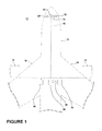
- Figure 1 schematically illustrates a portion of an aircraft 10 providing an environment for an embodiment of the present disclosure.
- One or more propulsion or jet engines 12 coupled to a fuselage 14, a cockpit 16 positioned in the fuselage 14, and wing assemblies 18 extending outward from the fuselage 14 may be included in the aircraft 10.
- a plurality of systems 20 that enable proper operation of the aircraft 10 may be included and may be operably coupled through a communication network 22 to a flight control computer 24. It may be desired during the life cycle of an apparatus, such as a jet engine 12, to determine information regarding the jet engine 12 including by way of non-limiting example a health of the jet engine 12.
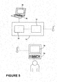
- Figure 2 illustrates a diagnostic system 30 suitable for determining the health, both diagnosing and prognosing, of any apparatus, including by way of non-limiting example a jet engine 12, which may have one or more sources of radiation.
- the jet engine 12 may be a source of portions of full-spectrum radiation, especially sources from electromechanical interference generated by rotating or reciprocating component in the apparatus, which may create among other things electromagnetic radiation.
- the system 30 has a diagnostic tool 32, a signal module 34, a processor 36, and a display 38 according to an embodiment of the invention.
- the diagnostic system 30 is illustrated merely for exemplary purposes and may represent a typical system for a rotating apparatus such as a jet engine 12. It will be understood that the configuration of the diagnostic system 30 may be modified for use with alternative apparatuses.
- the diagnostic tool 32 may include a diagnostic blanket or wrapper 40, which may be wrapped about the jet engine 12 and which has one or more sensors for sensing health data of the jet engine 12. It is contemplated that the wrapper 40 may include a sheet, which may at least partially envelope the apparatus and that the sensors may include an antenna assembly 42, which may include one or more antenna to receive user selected portions of the full spectrum radiation from the apparatus.
- the sheet of the wrapper 40 may be flexible, rigid, or a combination of flexible and rigid.
- the antenna assembly 42 may be located on or included in the wrapper 40.
- the shape of the wrapper 40 may define a cylinder with a centerline 44 along which the jet engine 12 may be inserted.
- the wrapper 40 is cylindrically shaped such that it may circumscribe the jet engine 12 allowing circumferential zones to have similar antenna assemblies 42 to identify similar or dissimilar circumferential radiation areas. It is contemplated that the wrapper 40 may alternatively fully envelope the jet engine 12 and that the wrapper 40 may be configured in a shape defining an interior sized to receive the jet engine 12. While illustrated as a cylinder for convenience of description, the wrapper may be configured into a variety of different shapes. The wrapper may follow the contours of the jet engine and all or part of the wrapper may lie in contact with the jet engine.
- the antenna assembly 42 has been illustrated in a cylinder configuration it may be understood that this configuration may be impractical for some applications due to a variety of mechanical obstructions. Thus, it is contemplated that the antenna assembly 42 may be broken up into identifiable zones and that such zones may provide equivalent results. Regardless of the number of zones, it will be understood that each of these zones may be the same radial distance from a center line 44 of the jet engine 12. In cases where this is also impractical, the signal module 34 and/or processor 36 may correct for any signal strength losses due to the distance variation.
- the antenna assembly 42 may be configured to output at least one emission signal indicative of at least some portion of a full spectrum radiation that may be emitted by the jet engine 12 during operation.
- the antenna assembly 42 is only shown on a portion of the wrapper 40 for clarity purposes and may take on any geometric shape based on the requirements of the desired radiation to be received. It is contemplated that the antenna assembly 42 may be designed and tuned to receive a signal having a frequency emitted by the jet engine 12. For example, the antenna assembly 42 may be designed and tuned to the same frequency as a known emission source in the jet engine 12.
- the antenna assembly 42 may be configured to receive multiple frequencies and that the antenna assembly 42 may be designed to receive multiple signals of different frequencies emitted by the jet engine 12 with the ability to selectively tune to the desired frequency or frequency bandwidth through use of the signal module 34. It is contemplated that the antenna assembly 42 may include a fractal antenna. Such fractal antenna assemblies 42 may be very compact and may be considered multiband or wideband such that they may be configured to receive multiple frequencies in desired portions of the full radiation spectrum including electromagnetic radiation. The antenna assembly 42 may include multiple fractal antenna assemblies that are matched in both location on the wrapper 40 and frequency to a known emission source from the jet engine 12.
- the antenna assembly 42 may include an antenna array of multiple antenna assemblies 42, which may be configured in a variety of ways or combination of ways. For example, each of the antennas being configured to receive one or more frequencies; they may be configured to receive the same, similar or different frequencies; the antennas may be located at different locations about the wrapper, such as adjacent to a user selected portion of the full spectrum radiation source that emits at a frequency that corresponds to the one or more frequencies the antenna is configured to receive.
- the antenna may be operably coupled to the signal module 34 and may output at least one emission signal indicative of at least some portion of full-spectrum radiation emitted by the jet engine 12 to the signal module 34.
- the signal module 34 may be configured to provide specific filtering of the emission signal sent from the antenna assembly 42.
- the signal module 34 may be configured to provide specific filtering to station specific or system zone specific input signals of the antenna assembly 42.
- the signal module 34 may include any suitable module for providing filtering and tailored accuracy for the sought after frequencies. It is contemplated that such a signal module 34 may be capable of programing filter cutoff or notch frequencies.
- the signal module 34 may also include a memory device (not shown) for storing both the filtered and unfiltered emission signals.
- the processor 36 may receive the emission signal from such a memory device.
- the processor 36 may be configured to receive the emission signal and convert the emission signal into a human readable form.
- the processor 36 may be operably coupled to the display 38, which may be configured for displaying the human readable form.
- the display 38 may be configured to display the human readable form of the emission signal.
- Such a human readable form of the emission signal 50 is schematically illustrated in Figure 2 and may take any suitable form.
- the display 38 may be capable of real time display and data storage although this may not be required for system operation, such real time data processing would aid in operator notification of anomalies through the graphical representation of the data. This may be especially important during a development stage for the jet engine 12.
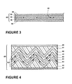
- the wrapper 40 may be formed of multiple layers.
- the wrapper 40 may include a laminate layer 60 such as polyester film.
- a flexible printing process may be used to print the antenna assembly 42 on such a laminate layer 60.
- the wrapper 40 may include a multi-layer sheet, with the antenna assembly 42 provided on a layer to define an antenna layer 62.
- Antenna designs on the antenna layer 62 may be easily updated or changed based on the physical size of the intended apparatus and desired bandwidth.
- any antenna or combination of antenna assemblies 42 may easily be adapted to the laminate layer 60 of the wrapper 40, tested, and applied.
- an electrical shielding layer 64 may be included adjacent the antenna layer 62.
- a first protective layer 66 may be included adjacent one of the antenna layer 62 and the electrical shielding layer 64.
- a second protective layer 68 may be included adjacent the other of the antenna layer 62 and the electrical shielding layer 64. It is contemplated that the first and second protective layers 66 and 68 may include a polyester film and that the electrical shielding layer 64 may include a conductive film or an aluminum sheet.
- FIG 4 illustrates an alternative wrapper 40 for creating an alternative diagnostic tool.
- the illustrated alternative wrapper 40 includes a corrugated formation as well as an alternative antenna assembly 42. More specifically, not only are polyester film layers 61, electrical shielding layers 65, and an insulator layer 67 included to make the multi-layer wrapper 40, the antenna assembly 42 also includes multiple layers. More specifically, the antenna assembly 42 is illustrated as being formed by multiple antenna layers 63 spaced from each other by a polyester film layer 61. Such an antenna assembly 42 may be thought of as a piezo antenna assembly, which may be capacitive in design and may detect radiation at lower frequencies from the inductive designs described above. For the purpose of this description, the antenna assembly 42 may be either inductive or capacitive and are not limited to any geometry such that they may vary from traditional antennas to fractal designs.
- the diagnostic tool 32 of the diagnostic system 30 may receive electro-mechanical emissions from the jet engine 12. Such emissions may be filtered or otherwise conditioned by the signal module 34 and may be recorded or displayed. For example, the location dependent frequency information may be displayed in a human readable form including the statistical mean, minimum, maximum and standard deviation of the sampled data.
- the emission signals may be sent to the processor 36 for evaluation and comparison at one point in the life of the jet engine or throughout the life of the jet engine 12. It is contemplated that statistical processing of the data may be done either on the processor 36 or on another processor.
- Such processing may permit engine-to-engine, fleet-to-fleet, and shop-to-shop trending, diagnostic, and prognostic applications to be applied. It is contemplated that such post processing software and the conversion of the emission signal into a human readable form and the display of same may be expandable with learning.
- Examples of when the diagnostic system may be used include, for example, during production to establish a baseline or blueprint for at least a portion of a full spectrum radiation profile of each jet engine 12.
- the diagnostic system 30 may also be used to establish a checkup radiation profile at one or more later times during the life cycle of the jet engines 12.
- the baseline and checkup profiles may be compared to each other in a variety of ways for a variety of diagnostic and prognostic benefits.
- the portions of the diagnostic system 30 may be integral to the jet engine 12 and may be plugged into by the remainder of the diagnostic system 30 for periodic inspections.
- an in service version of the diagnostic system 30 may be provided and such an in service version may compare real time profiles and transmit fault reports through a wireless system (not shown) so that a maintainer of the aircraft 10 may be notified to the changing trends before damage to the jet engine 12 worsens.
- the above described diagnostic system 30 may be used to implement a method of diagnosing manufacturing variances in such jet engines 12.
- Such a method may include an antenna assembly 42 in the form of an antenna array.
- An embodiment of such a method may include a) at least partially enveloping the jet engine 12 in the antenna assembly 42 after manufacture and prior to the jet engine 12 being put into service, b) establishing a baseline profile for the jet engine 12 by detecting the radiation received from the antenna assembly 42 while the jet engine 12 is operating, c) saving the baseline profile for the jet engine 12, d) repeating a-c for multiple jet engines 12 to form a set of baseline profiles for the multiple jet engines 12, and e) comparing the set of baseline profiles to determine a difference indicative of a variance in the manufacturing of the jet engines 12.
- the technical effect being that anomalies or differences in the jet engines 12 may be determined based on the differences.
- the diagnostic system 30 may address manufacturing variation based on comparing the baseline profiles across multiple jet engines 12. Changes or trends in the compared baseline profiles may be used in finding production anomalies affecting the jet engine during testing. Trends leading up to a rejected system being tested may indicate production issues. Comparing data leading up to a rejected system being tested may isolate the root cause for the change.
- the above described diagnostic system 30 may also be used to implement a method of diagnosing a health of the jet engine 12.
- Such a method may include an antenna assembly 42 in the form of an antenna array.
- An embodiment of such a method may include at least partially enveloping the jet engine 12 in the antenna assembly 42, establishing a baseline profile by detecting the radiation received from the antenna assembly 42 at a first time and recording the baseline profile, establishing a checkup profile by detecting the radiation received from the antenna assembly at a second time, subsequent to the first time, and comparing the checkup profile to the baseline profile to determine a difference indicative of the health of the jet engine 12.
- the baseline profile may be established during a known healthy state of the jet engine 12.
- the known healthy state may include a completion of the manufacturing of the jet engine 12.
- Such a method may include an antenna assembly 42 in the form of an antenna array.
- An embodiment of such a method may include a) at least partially enveloping the jet engine 12 in the antenna assembly 42, b) establishing a profile for the jet engine 12 by detecting the radiation received from the antenna assembly while the jet engine 12 is operating, c) saving the profile for the jet engine 12, d) repeating a-c across multiple jet engines 12 at multiple times to form a set of historical profiles for the multiple jet engines 12, and e) identifying at least one anomaly in the set of historical profiles that is indicative of a future failure. It is contemplated that establishing a profile may be limited to establishing a user defined portion of the full spectrum radiation. By way of non-limiting example an electromagnetic profile for the jet engine 12 may be established.
- multiple jet engines 12 share at least one common component.
- the multiple jet engines 12 may even be the same type of jet engine 12.
- a failure may be identified in the jet engine 12 and that the failure may be associated with the identified anomaly.
- the identified failure may be used to identify the associated anomaly.
- the method may also include analyzing the historical profiles (baseline and checkup profiles) of each of the other jet engines 12 for the anomaly. When the anomaly is detected in the historical profile, an alert of a potential failure may be sent out.
- the profiles may include baseline profiles that are recorded upon completion of the manufacturing for the jet engine 12 and before the jet engine 12 is put into service.
- the profiles include checkup profiles that are recorded after the corresponding baseline profile.
- the profile database 70 and the maintenance database 72 may be any suitable type of databases, including a single database having multiple sets of data, multiple discrete databases linked together, or even a simple table of data. Regardless of the types of databases the profile database 70 and the maintenance database 72 may be provided on storage medium on a computer (not shown) or may be provided on a computer readable medium, such as a database server. It is contemplated that the profile database 70 and maintenance database 72 may be provided on the same computer or database server (shown schematically as 74). Alternatively, the profile database 70 and the maintenance database 72 may be located on separate computers or separate database servers.
- the information in the profile database 70 and maintenance database 72 may be analyzed in a variety of ways for health diagnostics and prognostics purposes.
- a processor on the computer itself may be used for such diagnostic and prognostic purposes and may communicate the results of the analysis via a display or may transmit the results to a local or remote user.
- a separate computer may access the profile database 70 and maintenance database 72.
- the processor 36 is illustrated as being operably coupled to the profile database 70 and maintenance database 72 and may analyze the data therein and communicate the results of such analysis on the display 38.
- a remote computer having a processor 76 and a display 78 may be operably coupled to the profile database 70 and maintenance database 72 and may analyze the data therein and communicate the results of such analysis to a remote user.
- the computers may access the profile database 70 and maintenance database 72 via a communication network or computer network coupling the profile database 70 and maintenance database 72 with the analyzing computer.
- a computer network may be a local area network or a larger network such as the internet. It is also contemplated that such a coupling may be made wirelessly or via a wired connection.
- the data may be filtered in any suitable manner including on an engine-by-engine basis, fleet-by-fleet basis, etc.
- An analysis may be done to make comparisons including comparisons between production models, comparisons between data from systems in service to original production data, and comparisons between systems in service to identify potential future failures.
- Such comparisons may include by way of non-limiting examples, fleet wide comparisons, cycle count comparisons, and pre and post maintenance comparisons.
- the technical effect is that information from the diagnostic system related to the health of the entire jet engine may be compared in a variety of ways and may be correlated with a variety of other information related to the engine such that various analyses may take place.
- detecting any portion of the full-spectrum radiation may include receiving the portion of the full-spectrum radiation from a multi-frequency antenna forming the antenna assembly 42.
- the multi-frequency antenna may include a fractal antenna. It is contemplated that in all of the above described methods that the jet engine 12 may be fully enveloped in the antenna assembly 42.
- the antenna assembly 42 may be designed and tuned to at least some portion of the full spectrum frequencies emitted by the jet engine 12. It is contemplated that the antenna assembly may be selectively tuned for each portion of the jet engine 12. The antenna assembly may be tuned in a variety of ways including that an antenna configured to receive the known frequencies may be selected. Tuning the antenna assembly may also include locating a selected antenna adjacent the jet engine 12 where the known frequency is emitted.
- the above described diagnostic system 30 may be configured to diagnose any electrical, mechanical, or electro-mechanical apparatus.
- the size and shape of the wrapper may be easily adapted to the apparatus being tested or monitored. For example, in larger apparatuses some frequencies may tend to be lower and the corresponding antennas 42 may be larger.
- the wrapper may be easily adapted to irregular and/or asymmetric systems.
- apparatuses that are moving fluids such as internal combustion engines, turbo-machinery etc.
- controlled environmental conditions may be maintained in a production test for systems affected by pressure and temperature
- the data collected for that apparatus may be corrected for pressure and temperature where applicable.
- data correction for pressure and temperature variations may not be applied.
- the above described embodiments provide a variety of benefits including a reduction in the time and effort needed to validate the health of an apparatus, which in turn may reduce on-going maintenance costs.
- the diagnostic system 30 may be specifically tailored for known physical relationships of the apparatus, and may be substituted for an otherwise overwhelming, cumbersome, and massive set of individual sensors.
- the antenna assembly may incorporate magnitude scaling of sensors at fractions of the weight of a typical sensor suite. Further, there will be a reduction of associated cables from such multiple sensors, a reduction of cable connectors, and a reduction of associated routing hardware. These reductions may amount to a substantial operational savings for weight critical systems including aeronautical applications.
- the reduction in the above mentioned items may also result in a reduction in the amount of required machining operations such as drilling, tapping, brackets, and fasteners, which may also result in a cost savings.
- the above described embodiments may also provide reliability benefits because reliability issues may be minimized due to the reduction in sensors, cables, and cable types, complex cable connectors, associated routing hardware. Further, that the system may use a single conditioning module may simplify input wiring schemes.
- the above described embodiments may also provide more reliable diagnostics as they may achieve a representation of the entire apparatus as opposed to typical sensor suites that may have only a single isolated discrete location.
Landscapes
- Physics & Mathematics (AREA)
- Engineering & Computer Science (AREA)
- Aviation & Aerospace Engineering (AREA)
- General Physics & Mathematics (AREA)
- Electromagnetism (AREA)
- Testing Of Engines (AREA)
- Arrangements For Transmission Of Measured Signals (AREA)
Applications Claiming Priority (1)
| Application Number | Priority Date | Filing Date | Title |
|---|---|---|---|
| US13/303,238 US20130132033A1 (en) | 2011-11-23 | 2011-11-23 | System and apparatus for radiation diagnosis |
Publications (1)
| Publication Number | Publication Date |
|---|---|
| EP2597450A2 true EP2597450A2 (de) | 2013-05-29 |
Family
ID=47358549
Family Applications (1)
| Application Number | Title | Priority Date | Filing Date |
|---|---|---|---|
| EP12193903.7A Withdrawn EP2597450A2 (de) | 2011-11-23 | 2012-11-22 | System und Vorrichtung zur Strahlungsdiagnose |
Country Status (6)
| Country | Link |
|---|---|
| US (1) | US20130132033A1 (de) |
| EP (1) | EP2597450A2 (de) |
| JP (1) | JP2013108499A (de) |
| CN (1) | CN103135010A (de) |
| BR (1) | BR102012028386A2 (de) |
| CA (1) | CA2795590A1 (de) |
Family Cites Families (13)
| Publication number | Priority date | Publication date | Assignee | Title |
|---|---|---|---|---|
| JP3251799B2 (ja) * | 1995-02-13 | 2002-01-28 | 三菱電機株式会社 | 機器の診断装置 |
| MXPA02004221A (es) * | 1999-10-26 | 2003-08-20 | Fractus Sa | Agrupaciones multibanda de antenas entrelazadas. |
| DE10359930A1 (de) * | 2003-01-23 | 2004-08-05 | Siemens Ag | Verfahren zum Ermitteln der Beanspruchung von Schaufeln einer Strömungsmaschine während des Betriebs sowie entsprechende Vorrichtung zur Durchführung des Verfahrens |
| CN1748129A (zh) * | 2003-01-23 | 2006-03-15 | 西门子公司 | 在运行中确定涡轮机叶片应力的方法以及实施此方法的相应设备 |
| CN100363747C (zh) * | 2005-04-26 | 2008-01-23 | 重庆大学 | 气体绝缘组合电器局部放电超高频检测装置及方法 |
| US7289073B2 (en) * | 2005-08-19 | 2007-10-30 | Gm Global Technology Operations, Inc. | Method for improving the efficiency of transparent thin film antennas and antennas made by such method |
| FR2901610B1 (fr) * | 2006-05-24 | 2009-01-16 | Airbus France Sas | Dispositif de controle non destructif d'une struture par analyse vibratoire |
| EP1870718A1 (de) * | 2006-06-23 | 2007-12-26 | The Swatch Group Research and Development Ltd. | Vorrichtung zur Messung des Abstrahlungsdiagramms einer Sendeantenne |
| US8643539B2 (en) * | 2008-11-19 | 2014-02-04 | Nokomis, Inc. | Advance manufacturing monitoring and diagnostic tool |
| US8594961B2 (en) * | 2009-02-15 | 2013-11-26 | Board Of Regents, The University Of Texas System | Remote interrogation of a passive wireless antenna sensor |
| DE112009004421T8 (de) * | 2009-02-25 | 2012-09-13 | Fraunhofer-Gesellschaft zur Förderung der angewandten Forschung e.V. | RFID-Abtastsystem ohne äußere Energieversorgung zur Abfrage des strukturellen Befindens |
| WO2011031825A2 (en) * | 2009-09-10 | 2011-03-17 | Rf Controls, Llc | Calibration and operational assurance method and apparatus for rfid object monitoring systems |
| CN201845070U (zh) * | 2010-11-18 | 2011-05-25 | 山东电力集团公司泰安供电公司 | 一种配电网络电力设备内部放电监测传感器 |
-
2011
- 2011-11-23 US US13/303,238 patent/US20130132033A1/en not_active Abandoned
-
2012
- 2012-11-06 BR BRBR102012028386-7A patent/BR102012028386A2/pt not_active IP Right Cessation
- 2012-11-15 CA CA2795590A patent/CA2795590A1/en not_active Abandoned
- 2012-11-19 JP JP2012252804A patent/JP2013108499A/ja active Pending
- 2012-11-22 CN CN2012104772933A patent/CN103135010A/zh active Pending
- 2012-11-22 EP EP12193903.7A patent/EP2597450A2/de not_active Withdrawn
Non-Patent Citations (1)
| Title |
|---|
| None |
Also Published As
| Publication number | Publication date |
|---|---|
| JP2013108499A (ja) | 2013-06-06 |
| BR102012028386A2 (pt) | 2015-07-28 |
| US20130132033A1 (en) | 2013-05-23 |
| CN103135010A (zh) | 2013-06-05 |
| CA2795590A1 (en) | 2013-05-23 |
Similar Documents
| Publication | Publication Date | Title |
|---|---|---|
| EP2597449A2 (de) | Verfahren zur Prognose eines Zustandsproblems einer Vorrichtung | |
| EP2570879B1 (de) | Konditionierungsüberwachungssystem und Verfahren | |
| US20230115963A1 (en) | Mechanical failure detection system and method | |
| EP3441947A1 (de) | System und verfahren zur bestimmung der verbleibenden nutzungsdauer | |
| US7254520B2 (en) | Testing of wire systems and end devices installed in industrial processes | |
| EP2770391B1 (de) | Diagnostisches Verfahren und System für ein Flugzeug | |
| US9469417B2 (en) | System and method for fault diagnosis of aircraft | |
| KR102545672B1 (ko) | 기계고장 진단 방법 및 장치 | |
| WO2014143812A2 (en) | Multi-modal fluid condition sensor platform and system thereof | |
| KR20140072331A (ko) | 이상진단 사전감시 방법 | |
| Davari et al. | A fault detection framework based on lstm autoencoder: A case study for volvo bus data set | |
| EP2597447A2 (de) | Verfahren zur Diagnose des Zustands einer Vorrichtung | |
| US7366627B2 (en) | Method for satisfying certification requirements and verifying the integrity of structural health management systems | |
| EP2597448A2 (de) | Verfahren zur Diagnose von Herstellungsabweichungen | |
| EP2597450A2 (de) | System und Vorrichtung zur Strahlungsdiagnose | |
| BR102012029569A2 (pt) | Método de prognóstico de problema de integridade em um aparelho elétrico | |
| US11249050B2 (en) | Device and method for detecting faults of a structure | |
| CN119739979B (zh) | 一种基于phm的煤矿设备故障检测方法、介质及系统 | |
| Sultanov et al. | ABOUT THE PRINCIPLES AND PERSPECTIVES OF AUTOMOBILE DIAGNOSIS | |
| Pausder-Fanny et al. | ANALYSIS OF THE CORRELATION BETWEEN ENGINE FAILURES AND ODOMETER VALUE OF DIFFERENT KIND OF CARS BY USING BIG DATA ANALYTIC TOOLS | |
| Xi et al. | Condition monitoring and plenary diagnostics strategy based on event driven threads |
Legal Events
| Date | Code | Title | Description |
|---|---|---|---|
| PUAI | Public reference made under article 153(3) epc to a published international application that has entered the european phase |
Free format text: ORIGINAL CODE: 0009012 |
|
| AK | Designated contracting states |
Kind code of ref document: A2 Designated state(s): AL AT BE BG CH CY CZ DE DK EE ES FI FR GB GR HR HU IE IS IT LI LT LU LV MC MK MT NL NO PL PT RO RS SE SI SK SM TR |
|
| AX | Request for extension of the european patent |
Extension state: BA ME |
|
| STAA | Information on the status of an ep patent application or granted ep patent |
Free format text: STATUS: THE APPLICATION IS DEEMED TO BE WITHDRAWN |
|
| 18D | Application deemed to be withdrawn |
Effective date: 20170601 |