EP2597416A2 - Penetrator round assembly - Google Patents
Penetrator round assembly Download PDFInfo
- Publication number
- EP2597416A2 EP2597416A2 EP12193724.7A EP12193724A EP2597416A2 EP 2597416 A2 EP2597416 A2 EP 2597416A2 EP 12193724 A EP12193724 A EP 12193724A EP 2597416 A2 EP2597416 A2 EP 2597416A2
- Authority
- EP
- European Patent Office
- Prior art keywords
- penetrator
- main
- rod
- nose
- penetrator rod
- Prior art date
- Legal status (The legal status is an assumption and is not a legal conclusion. Google has not performed a legal analysis and makes no representation as to the accuracy of the status listed.)
- Granted
Links
Images


Classifications
-
- F—MECHANICAL ENGINEERING; LIGHTING; HEATING; WEAPONS; BLASTING
- F42—AMMUNITION; BLASTING
- F42B—EXPLOSIVE CHARGES, e.g. FOR BLASTING, FIREWORKS, AMMUNITION
- F42B12/00—Projectiles, missiles or mines characterised by the warhead, the intended effect, or the material
- F42B12/02—Projectiles, missiles or mines characterised by the warhead, the intended effect, or the material characterised by the warhead or the intended effect
- F42B12/04—Projectiles, missiles or mines characterised by the warhead, the intended effect, or the material characterised by the warhead or the intended effect of armour-piercing type
- F42B12/06—Projectiles, missiles or mines characterised by the warhead, the intended effect, or the material characterised by the warhead or the intended effect of armour-piercing type with hard or heavy core; Kinetic energy penetrators
-
- F—MECHANICAL ENGINEERING; LIGHTING; HEATING; WEAPONS; BLASTING
- F42—AMMUNITION; BLASTING
- F42B—EXPLOSIVE CHARGES, e.g. FOR BLASTING, FIREWORKS, AMMUNITION
- F42B14/00—Projectiles or missiles characterised by arrangements for guiding or sealing them inside barrels, or for lubricating or cleaning barrels
- F42B14/06—Sub-calibre projectiles having sabots; Sabots therefor
- F42B14/061—Sabots for long rod fin stabilised kinetic energy projectiles, i.e. multisegment sabots attached midway on the projectile
Definitions
- the disclosure generally relates to munitions and, more particularly, to projectiles that can penetrate reactive armor.
- Explosive reactive armor is a type of vehicle armor that is designed to reduce the amount of penetration of projectiles, e.g., anti-tank rounds.
- explosive reactive armor includes an explosive material sandwiched between two plates, e.g., metal plates. The plates and explosive material form a block-like module. Numerous modules are distributed over the base armor of a vehicle, e.g., tank, in order to form a protective layer of explosive reactive armor.
- the explosive reactive armor is designed to deflect a projectile by altering the angle of incidence of the projectile to prevent the projectile from perforating the base armor of the vehicle. More particularly, as the projectile impacts the outermost plate of an explosive reactive armor module, the explosive material ignites. The ignition of the explosive material causes the two plates of the module to be driven apart. As the outer (or cover) plate is driven outward into the projectile, the outer plate damages, e.g., breaks or bends, the penetrator rod of the projectile. As the inner plate is driven inward away from the projectile, a longer path-length is created for the projectile, thereby reducing the chance that the projectile will perforate the vehicle's base armor.
- This disclosure generally describes a penetrator round assembly having a main penetrator rod and nose designed to penetrate explosive reactive armor.
- the penetrator round assembly perforates explosive reactive armor ("ERA") cover plates and absorbs the initial energy from the moving ERA plates without significantly bending the main penetrator rod.
- ERA explosive reactive armor
- this disclosure is directed to a penetrator round assembly comprising a main penetrator rod comprising a tungsten alloy, and a solid nose engaged to the main penetrator rod.
- this disclosure is directed to a penetrator round assembly comprising a main penetrator rod comprising a tungsten alloy, and a solid steel nose engaged to the main penetrator rod, wherein a ratio of a length of the main penetrator rod and a diameter of the main penetrator rod is greater than about 25.
- this disclosure is directed to a penetrator round assembly comprising a main penetrator rod comprising a tungsten alloy, and a solid steel nose engaged to the main penetrator rod, wherein a ratio of a length of the main penetrator rod and a diameter of the main penetrator rod is greater than about 25, wherein neither the main penetrator rod nor the nose comprise depleted uranium, and wherein the main penetrator rod does not comprise cobalt.
- FIG. 1 is a perspective view of an example penetrator round assembly, in accordance with this disclosure.
- FIG. 2 is a longitudinal cross-sectional view of a portion of the example penetrator round of FIG. 1 .
- FIG. 3 is a schematic view of an example main penetrator rod and nose assembly, in accordance with this disclosure.
- FIG. 4 is a graph depicting relative base armor penetration at various ranges for two penetrator round assemblies against ERA.
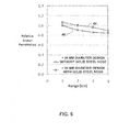
- FIG. 5 is a graph depicting relative base armor penetration at various ranges for two penetrator round assemblies against semi-infinite rolled homogeneous armor (RHA).
- this disclosure describes a penetrator round assembly having a main penetrator rod and nose designed to penetrate explosive reactive armor.
- the penetrator round assembly includes a solid steel nose that is sufficiently robust to perforate explosive reactive armor ("ERA") cover plates and absorb the initial energy from the moving ERA cover plates without significantly bending the main penetrator rod of the assembly.
- ERA explosive reactive armor
- the main penetrator rod of the assembly has a greater bending stiffness than other penetrator round assemblies, thereby allowing the main penetrator rod of this disclosure to absorb the grinding interaction of moving ERA cover plates better than the other penetrator round assemblies.
- the penetrator round assembly described in this disclosure allows a user to engage enemy vehicles, e.g., tanks, at longer ranges as compared to other penetrator round assemblies. A longer engagement range increases the chance that the user will survive the encounter with enemy forces.
- FIG. 1 is a perspective view of an example penetrator round assembly, in accordance with this disclosure.
- the example penetrator round assembly of FIG. 1 shown generally at 10, includes combustible cartridge case system 12, spring disc 14, visibility tracer 16, electric primer 18, case base and seal assembly 20, stick propellant 22, propellant bag 24, sabot 26, nylon obturator 28, anti-split ring 30, main penetrator rod 32, nose 34, and fins 36.
- penetrator round assembly 10 is fired from the main gun of a tank.
- main penetrator rod 32 in contrast to other penetrator round assemblies currently available, does not include depleted uranium. Rather, main penetrator rod 32 is comprised of an alloy containing a minimum of 90% tungsten by weight. The tungsten alloy of main penetrator rod 32 does not, however, include cobalt.
- nose 34 is comprised of solid steel, e.g., solid stainless steel. Nose 34 does not include depleted uranium. Because of its solid design, nose 34 will perforate ERA cover plates, ignite the explosive material, and absorb the initial energy from the moving ERA cover plates without significantly bending the main penetrator rod of the assembly. As the ERA cover plates move, the cover plates erode away nose 34 rather than damaging main penetrator rod 32. In this manner, nose 34 can be thought of as a sacrificial element. That is, nose 34 takes the brunt of the effects of the explosion from the ERA, thereby allowing main penetrator rod 32 to continue straight without substantially bending or deflecting. While this disclosure refers specifically to a solid steel nose, it should be noted that nose 34 may be made of a material other than steel, provided that the material has a density that is greater than or equal to steel.
- hollow steel noses In contrast to nose 34, other currently available penetrator round assemblies utilizes hollow steel noses.
- the hollow steel nose design acts as a windshield for the round and is used for aerodynamic purposes rather than for penetrating cover plates, as described in this disclosure.
- FIG. 2 is a longitudinal cross-sectional view of a portion of the example penetrator round of FIG. 1 .
- Nose 34 is joined directly to main penetrator 32.
- main penetrator 32 includes threaded portion 38 upon which a portion nose 34 is attached.
- FIG. 3 is a schematic view of an example main penetrator rod and nose assembly, in accordance with this disclosure.
- main penetrator rod 32 has a length greater than 630 millimeters (mm) and the nose 34 has a length of greater than 100 mm.
- main penetrator rod 32 has a length greater than about 630 mm, preferably greater than about 650 mm, and more preferably greater than about 670 mm.
- main penetrator rod 32 has a diameter of greater than 24 mm. In one example configuration, main penetrator rod 32 has a diameter of about 25 mm. By utilizing a diameter greater than 24 mm, main penetrator rod 32 can absorb the grinding interaction of moving ERA plates better than rods with small diameters due to its increased bending stiffness.
- the length-to-diameter ratio is greater than about 25 for the penetrator round assembly.
- main penetrator rod 32 does not include depleted uranium. Rather, main penetrator rod 32 is comprised of a tungsten alloy. The alloy comprises at least 90% tungsten and further includes nickel and iron, but does not include cobalt.
- FIG. 4 is a graph depicting relative base armor penetration at various ranges for two penetrator round assemblies against ERA.
- FIG. 4 depicts predicted base armor penetration (y-axis) of a vehicle protected by ERA using a penetrator round assembly that has a diameter that is greater than about 24 mm and uses a solid steel nose, in accordance with this disclosure, relative to a penetrator round assembly that has a diameter less than 24 mm diameter and uses a hollow nose design over a range of 4 kilometers (km) (x-axis).
- the armor penetration is normalized by the penetration depth of the penetrator round assembly that uses a hollow nose design at 1 km. As seen in FIG.
- the design with the solid steel nose, indicated by line 40 outperforms the design with a hollow nose design, indicated by line 42, by at least 20% over a range of about 1-4 km. That is, the design with the solid steel nose, as described in this disclosure, perforates the base armor to a depth that is at least 20% more than the hollow nose design over a range of about 1-4 kilometers (km).
- FIG. 5 is a graph depicting relative base armor penetration at various ranges for two penetrator round assemblies against semi-infinite rolled homogeneous armor (RHA).
- FIG. 5 depicts the predicted base armor penetration (y-axis) of a vehicle protected by RHA using a penetrator round assembly that has a diameter greater than about 24 mm and uses a solid steel nose, in accordance with this disclosure, relative to a penetrator round assembly that has a diameter less than 24 mm and uses a hollow nose design over a range of 4 km (x-axis).
- the armor penetration is normalized by the penetration depth of the penetrator round assembly that uses a hollow nose design at 1 kilometer (km). As seen in FIG.
- the design with the solid steel nose, indicated by line 44 outperforms the design with a hollow nose design, indicated by line 46, over a range of about 1-4 kilometers (km). That is, the design with the solid steel nose, as described in this disclosure, perforates the base armor to a depth that is deeper than that of the hollow nose design over a range of about 1-4 kilometers (km).
Landscapes
- Engineering & Computer Science (AREA)
- General Engineering & Computer Science (AREA)
- Chemical & Material Sciences (AREA)
- Combustion & Propulsion (AREA)
- Buildings Adapted To Withstand Abnormal External Influences (AREA)
- Mechanical Treatment Of Semiconductor (AREA)
- Braking Arrangements (AREA)
- Processing Of Stones Or Stones Resemblance Materials (AREA)
- Vibration Dampers (AREA)
- Aiming, Guidance, Guns With A Light Source, Armor, Camouflage, And Targets (AREA)
- Emergency Lowering Means (AREA)
Abstract
Description
- The disclosure generally relates to munitions and, more particularly, to projectiles that can penetrate reactive armor.
- Explosive reactive armor is a type of vehicle armor that is designed to reduce the amount of penetration of projectiles, e.g., anti-tank rounds. In general, explosive reactive armor includes an explosive material sandwiched between two plates, e.g., metal plates. The plates and explosive material form a block-like module. Numerous modules are distributed over the base armor of a vehicle, e.g., tank, in order to form a protective layer of explosive reactive armor.
- Generally speaking, in operation the explosive reactive armor is designed to deflect a projectile by altering the angle of incidence of the projectile to prevent the projectile from perforating the base armor of the vehicle. More particularly, as the projectile impacts the outermost plate of an explosive reactive armor module, the explosive material ignites. The ignition of the explosive material causes the two plates of the module to be driven apart. As the outer (or cover) plate is driven outward into the projectile, the outer plate damages, e.g., breaks or bends, the penetrator rod of the projectile. As the inner plate is driven inward away from the projectile, a longer path-length is created for the projectile, thereby reducing the chance that the projectile will perforate the vehicle's base armor.
- This disclosure generally describes a penetrator round assembly having a main penetrator rod and nose designed to penetrate explosive reactive armor. Using various techniques described in this disclosure, the penetrator round assembly perforates explosive reactive armor ("ERA") cover plates and absorbs the initial energy from the moving ERA plates without significantly bending the main penetrator rod.
- In one example, this disclosure is directed to a penetrator round assembly comprising a main penetrator rod comprising a tungsten alloy, and a solid nose engaged to the main penetrator rod.
- In another example, this disclosure is directed to a penetrator round assembly comprising a main penetrator rod comprising a tungsten alloy, and a solid steel nose engaged to the main penetrator rod, wherein a ratio of a length of the main penetrator rod and a diameter of the main penetrator rod is greater than about 25.
- In another example, this disclosure is directed to a penetrator round assembly comprising a main penetrator rod comprising a tungsten alloy, and a solid steel nose engaged to the main penetrator rod, wherein a ratio of a length of the main penetrator rod and a diameter of the main penetrator rod is greater than about 25, wherein neither the main penetrator rod nor the nose comprise depleted uranium, and wherein the main penetrator rod does not comprise cobalt.
- The details of one or more aspects of the disclosure are set forth in the accompanying drawings and the description below. Other features, objects, and advantages will be apparent from the description and drawings, and from the claims.
-
FIG. 1 is a perspective view of an example penetrator round assembly, in accordance with this disclosure. -
FIG. 2 is a longitudinal cross-sectional view of a portion of the example penetrator round ofFIG. 1 . -
FIG. 3 is a schematic view of an example main penetrator rod and nose assembly, in accordance with this disclosure. -
FIG. 4 is a graph depicting relative base armor penetration at various ranges for two penetrator round assemblies against ERA. -
FIG. 5 is a graph depicting relative base armor penetration at various ranges for two penetrator round assemblies against semi-infinite rolled homogeneous armor (RHA). - In general, this disclosure describes a penetrator round assembly having a main penetrator rod and nose designed to penetrate explosive reactive armor. The penetrator round assembly includes a solid steel nose that is sufficiently robust to perforate explosive reactive armor ("ERA") cover plates and absorb the initial energy from the moving ERA cover plates without significantly bending the main penetrator rod of the assembly. In addition, the main penetrator rod of the assembly has a greater bending stiffness than other penetrator round assemblies, thereby allowing the main penetrator rod of this disclosure to absorb the grinding interaction of moving ERA cover plates better than the other penetrator round assemblies. In addition, the penetrator round assembly described in this disclosure allows a user to engage enemy vehicles, e.g., tanks, at longer ranges as compared to other penetrator round assemblies. A longer engagement range increases the chance that the user will survive the encounter with enemy forces.
-
FIG. 1 is a perspective view of an example penetrator round assembly, in accordance with this disclosure. The example penetrator round assembly ofFIG. 1 , shown generally at 10, includes combustiblecartridge case system 12,spring disc 14,visibility tracer 16,electric primer 18, case base andseal assembly 20,stick propellant 22,propellant bag 24,sabot 26,nylon obturator 28,anti-split ring 30,main penetrator rod 32,nose 34, andfins 36. In some examples,penetrator round assembly 10 is fired from the main gun of a tank. - In accordance with this disclosure,
main penetrator rod 32, in contrast to other penetrator round assemblies currently available, does not include depleted uranium. Rather,main penetrator rod 32 is comprised of an alloy containing a minimum of 90% tungsten by weight. The tungsten alloy ofmain penetrator rod 32 does not, however, include cobalt. - In addition and in accordance with this disclosure,
nose 34 is comprised of solid steel, e.g., solid stainless steel.Nose 34 does not include depleted uranium. Because of its solid design,nose 34 will perforate ERA cover plates, ignite the explosive material, and absorb the initial energy from the moving ERA cover plates without significantly bending the main penetrator rod of the assembly. As the ERA cover plates move, the cover plates erode awaynose 34 rather than damagingmain penetrator rod 32. In this manner,nose 34 can be thought of as a sacrificial element. That is,nose 34 takes the brunt of the effects of the explosion from the ERA, thereby allowingmain penetrator rod 32 to continue straight without substantially bending or deflecting. While this disclosure refers specifically to a solid steel nose, it should be noted thatnose 34 may be made of a material other than steel, provided that the material has a density that is greater than or equal to steel. - In contrast to
nose 34, other currently available penetrator round assemblies utilizes hollow steel noses. The hollow steel nose design acts as a windshield for the round and is used for aerodynamic purposes rather than for penetrating cover plates, as described in this disclosure. -
FIG. 2 is a longitudinal cross-sectional view of a portion of the example penetrator round ofFIG. 1 . Nose 34 is joined directly tomain penetrator 32. In particular,main penetrator 32 includes threadedportion 38 upon which aportion nose 34 is attached. -
FIG. 3 is a schematic view of an example main penetrator rod and nose assembly, in accordance with this disclosure. In the example depicted inFIG. 3 ,main penetrator rod 32 has a length greater than 630 millimeters (mm) and thenose 34 has a length of greater than 100 mm. In other examples,main penetrator rod 32 has a length greater than about 630 mm, preferably greater than about 650 mm, and more preferably greater than about 670 mm. - In addition and in accordance with this disclosure,
main penetrator rod 32 has a diameter of greater than 24 mm. In one example configuration,main penetrator rod 32 has a diameter of about 25 mm. By utilizing a diameter greater than 24 mm,main penetrator rod 32 can absorb the grinding interaction of moving ERA plates better than rods with small diameters due to its increased bending stiffness. The bending stiffness of the main penetrator rod is proportional to the diameter of the road raised to the 4th power. For example a 25 mm diameter rod is approximately 67% stiffer than a 22 mm diameter rod (254/224 = 1.67). Importantly, the length-to-diameter ratio is greater than about 25 for the penetrator round assembly. - In addition and as indicated above,
main penetrator rod 32 does not include depleted uranium. Rather,main penetrator rod 32 is comprised of a tungsten alloy. The alloy comprises at least 90% tungsten and further includes nickel and iron, but does not include cobalt. -
FIG. 4 is a graph depicting relative base armor penetration at various ranges for two penetrator round assemblies against ERA. In particular,FIG. 4 depicts predicted base armor penetration (y-axis) of a vehicle protected by ERA using a penetrator round assembly that has a diameter that is greater than about 24 mm and uses a solid steel nose, in accordance with this disclosure, relative to a penetrator round assembly that has a diameter less than 24 mm diameter and uses a hollow nose design over a range of 4 kilometers (km) (x-axis). InFIG. 4 , the armor penetration is normalized by the penetration depth of the penetrator round assembly that uses a hollow nose design at 1 km. As seen inFIG. 4 , the design with the solid steel nose, indicated byline 40, outperforms the design with a hollow nose design, indicated byline 42, by at least 20% over a range of about 1-4 km. That is, the design with the solid steel nose, as described in this disclosure, perforates the base armor to a depth that is at least 20% more than the hollow nose design over a range of about 1-4 kilometers (km). -
FIG. 5 is a graph depicting relative base armor penetration at various ranges for two penetrator round assemblies against semi-infinite rolled homogeneous armor (RHA). In particular,FIG. 5 depicts the predicted base armor penetration (y-axis) of a vehicle protected by RHA using a penetrator round assembly that has a diameter greater than about 24 mm and uses a solid steel nose, in accordance with this disclosure, relative to a penetrator round assembly that has a diameter less than 24 mm and uses a hollow nose design over a range of 4 km (x-axis). InFIG. 5 , the armor penetration is normalized by the penetration depth of the penetrator round assembly that uses a hollow nose design at 1 kilometer (km). As seen inFIG. 5 , the design with the solid steel nose, indicated byline 44, outperforms the design with a hollow nose design, indicated byline 46, over a range of about 1-4 kilometers (km). That is, the design with the solid steel nose, as described in this disclosure, perforates the base armor to a depth that is deeper than that of the hollow nose design over a range of about 1-4 kilometers (km).
Various aspects of the disclosure have been described. These and other aspects are within the scope of the following claims.
Claims (14)
- A penetrator round assembly comprising:a main penetrator rod comprising a tungsten alloy; anda solid nose engaged to the main penetrator rod.
- The penetrator round assembly of claim 1, wherein the nose is a solid steel nose.
- The penetrator round assembly of any of the preceding claims, wherein the main penetrator rod has a monolithic construction.
- The penetrator round assembly of any of the preceding claims, wherein the main penetrator rod has a diameter of greater than about 24 millimeters.
- The penetrator round assembly of any of the preceding claims, wherein the main penetrator rod has a length greater than 630 millimeters.
- The penetrator round assembly of any of the preceding claims, wherein the nose has a length that is greater than about 100 millimeters.
- The penetrator round assembly of any of the preceding claims, wherein a ratio of a length of the main penetrator rod and a diameter of the main penetrator rod is greater than about 25.
- The penetrator round assembly of any of the preceding claims, wherein the main penetrator rods does not comprise depleted uranium.
- The penetrator round assembly of any of the preceding claims, wherein the nose does not comprise depleted uranium.
- The penetrator round assembly of any of the preceding claims, wherein the nose is configured to perforate an explosive reactive armor cover plate and absorb the initial energy from movement of the cover plate.
- A penetrator round assembly comprising:a main penetrator rod comprising a tungsten alloy; anda solid steel nose engaged to the main penetrator rod,wherein a ratio of a length of the main penetrator rod and a diameter of the main penetrator rod is greater than about 25.
- A penetrator round assembly comprising:a main penetrator rod comprising a tungsten alloy; anda solid steel nose engaged to the main penetrator rod,wherein a ratio of a length of the main penetrator rod and a diameter of the main penetrator rod is greater than about 25,wherein neither the main penetrator rod nor the nose comprise depleted uranium, andwherein the main penetrator rod does not comprise cobalt.
- A penetrator round assembly comprising:a main penetrator rod comprising a tungsten alloy; anda solid steel nose engaged to the main penetrator rod,wherein the main penetrator rod has a monolithic construction,wherein the main penetrator rod has a diameter of greater than about 24 millimeters,wherein the main penetrator rod has a length greater than 630 millimeters,wherein the nose has a length that is greater than about 100 millimeters,wherein a ratio of the length of the main penetrator rod and the diameter of the main penetrator rod is greater than about 25,wherein neither the main penetrator rod nor the nose comprise depleted uranium, andwherein the main penetrator rod does not comprise cobalt.
- A penetrator round assembly comprising:a main penetrator rod comprising a tungsten alloy; anda solid steel nose engaged to the main penetrator rod,wherein the main penetrator rod has a monolithic construction,wherein the main penetrator rod has a diameter of greater than about 24 millimeters,wherein the main penetrator rod has a length greater than 630 millimeters,wherein the nose has a length that is greater than about 100 millimeters,wherein a ratio of the length of the main penetrator rod and the diameter of the main penetrator rod is greater than about 25,wherein neither the main penetrator rod nor the nose comprise depleted uranium,wherein the main penetrator rod does not comprise cobalt, andwherein when the steel nose impacts a cover plate of an explosive reactive armor ("ERA") module, the steel nose absorbs an initial energy from a movement of the ERA cover plate without significantly bending the main penetrator rod.
Applications Claiming Priority (1)
| Application Number | Priority Date | Filing Date | Title |
|---|---|---|---|
| US201161562771P | 2011-11-22 | 2011-11-22 |
Publications (3)
| Publication Number | Publication Date |
|---|---|
| EP2597416A2 true EP2597416A2 (en) | 2013-05-29 |
| EP2597416A3 EP2597416A3 (en) | 2015-04-01 |
| EP2597416B1 EP2597416B1 (en) | 2018-10-17 |
Family
ID=47221973
Family Applications (1)
| Application Number | Title | Priority Date | Filing Date |
|---|---|---|---|
| EP12193724.7A Active EP2597416B1 (en) | 2011-11-22 | 2012-11-22 | Penetrator round assembly |
Country Status (3)
| Country | Link |
|---|---|
| US (1) | US8985026B2 (en) |
| EP (1) | EP2597416B1 (en) |
| IL (1) | IL223169A (en) |
Cited By (4)
| Publication number | Priority date | Publication date | Assignee | Title |
|---|---|---|---|---|
| US20130125774A1 (en) * | 2011-11-22 | 2013-05-23 | Alliant Techsystems Inc. | Penetrator round assembly |
| CN107848036A (en) * | 2015-07-22 | 2018-03-27 | 康·伯克兹公司 | The manufacture method of penetration device comprising the core surrounded by ductility sheath and this penetration device |
| DE102020116589A1 (en) | 2020-06-24 | 2021-12-30 | Rheinmetall Waffe Munition Gmbh | Penetrator, use of a penetrator and bullet |
| DE102020120747A1 (en) | 2020-08-06 | 2022-02-10 | Rheinmetall Waffe Munition Gmbh | Penetrator, use of a penetrator and projectile |
Families Citing this family (4)
| Publication number | Priority date | Publication date | Assignee | Title |
|---|---|---|---|---|
| US9488455B1 (en) | 2015-01-22 | 2016-11-08 | Consolidated Nuclear Security, LLC | Sabot assembly |
| DE102015110627A1 (en) * | 2015-07-01 | 2017-01-05 | Rwm Schweiz Ag | From a drawn gun barrel moldable, wing stabilized subcaliber bullet and method for its production |
| DE102015117018A1 (en) | 2015-10-06 | 2017-04-06 | Rheinmetall Waffe Munition Gmbh | Penetrator and subcaliber projectile |
| DE102019113325A1 (en) | 2019-05-20 | 2020-11-26 | Rheinmetall Waffe Munition Gmbh | Penetrator, use of a penetrator and bullet |
Family Cites Families (35)
| Publication number | Priority date | Publication date | Assignee | Title |
|---|---|---|---|---|
| GB579205A (en) | 1942-11-27 | 1946-07-26 | Joseph Fenwick Bridge | Improvements in or relating to armour-piercing projectiles |
| GB1095992A (en) | 1959-04-14 | 1967-12-20 | Secr Defence | Improvements in or relating to projectiles |
| DE1428679C1 (en) * | 1964-12-29 | 1977-09-15 | Deutsch Franz Forsch Inst | Hard core bullet for fighting tank targets |
| US3545383A (en) | 1965-10-27 | 1970-12-08 | Singer General Precision | Flechette |
| US3888636A (en) | 1971-02-01 | 1975-06-10 | Us Health | High density, high ductility, high strength tungsten-nickel-iron alloy & process of making therefor |
| GB1514908A (en) | 1974-01-22 | 1978-06-21 | Mallory Metallurg Prod Ltd | Armour piercing projectiles |
| DE2554600C1 (en) | 1975-12-04 | 1988-06-01 | Deutsch Franz Forsch Inst | Balancing bullet |
| DE3049623A1 (en) * | 1980-12-31 | 1982-07-29 | Knaus, Hans A.J., 7800 Freiburg | Armour piercing shell with solid nose - has charge with igniter enclosed between sleeve and rear end of tip |
| US4836108A (en) | 1981-08-31 | 1989-06-06 | Gte Products Corporation | Material for multiple component penetrators and penetrators employing same |
| DE3242591A1 (en) * | 1982-11-18 | 1984-05-24 | Rheinmetall GmbH, 4000 Düsseldorf | LOW-LENGTH / DIAMETER RATIO UNDER-CALIBRATION BULLET STOCK |
| DE3314752A1 (en) * | 1983-04-23 | 1984-10-31 | Rheinmetall GmbH, 4000 Düsseldorf | LACE BODY FOR A BALANCE SHEET |
| US4823703A (en) | 1987-08-11 | 1989-04-25 | The Titan Corporation | Armor penetrating and self-lubricating projectile |
| DE3802002A1 (en) | 1988-01-25 | 1989-08-10 | Kaltmann Hans Joachim | Projectile without any detonator or explosive, for weapons with barrels |
| US4841868A (en) | 1988-06-30 | 1989-06-27 | The United States Of America As Represented By The Secretary Of The Army | Composite long rod penetrator |
| DE3833001A1 (en) | 1988-09-29 | 1990-04-05 | Mauser Werke Oberndorf | SUB-CALIBRAL AMMUNITION |
| DE3919172C2 (en) | 1989-06-12 | 1997-03-20 | Deutsch Franz Forsch Inst | Arrow kinetic energy projectile |
| GB8925397D0 (en) | 1989-11-10 | 1992-11-04 | Secr Defence | Kinetic energy penetrator |
| US5198616A (en) | 1990-09-28 | 1993-03-30 | Bei Electronics, Inc. | Frangible armor piercing incendiary projectile |
| US5223667A (en) | 1992-01-21 | 1993-06-29 | Bei Electronics, Inc. | Plural piece flechettes affording enhanced penetration |
| US5445079A (en) | 1992-11-10 | 1995-08-29 | Giat Industries | Armor-piercing fragmentation projectile |
| DE19619341C2 (en) * | 1996-05-14 | 1999-11-11 | Rheinmetall W & M Gmbh | Sub-caliber balancing projectile and method for its production |
| US6085661A (en) | 1997-10-06 | 2000-07-11 | Olin Corporation | Small caliber non-toxic penetrator projectile |
| AU748098B2 (en) * | 1997-12-11 | 2002-05-30 | Lockheed Martin Corporation | Shrouded aerial bomb |
| FR2776372B1 (en) | 1998-03-19 | 2000-08-04 | Giat Ind Sa | PERFORATING SHELL ANTI CONCRETE STRUCTURES AND CONVERSION DEVICE FOR OBTAINING SUCH A PERFORATING SHELL FROM AN EXPLOSIVE SHELL |
| US6186072B1 (en) | 1999-02-22 | 2001-02-13 | Sandia Corporation | Monolithic ballasted penetrator |
| ATE202843T1 (en) | 1999-02-25 | 2001-07-15 | Contraves Pyrotec Ag | LOWER CALIBER BULLET |
| US6662726B1 (en) | 1999-03-08 | 2003-12-16 | General Dynamics Ordnance And Tactical Systems, Inc. | Kinetic energy penetrator |
| US6276277B1 (en) * | 1999-04-22 | 2001-08-21 | Lockheed Martin Corporation | Rocket-boosted guided hard target penetrator |
| ATE326681T1 (en) * | 2001-11-28 | 2006-06-15 | Futurtec Ag | BULLETS OF HIGH PENETRATION AND LATERAL IMPACT WITH INTEGRATED DISASSEMBLY DEVICE |
| DE10305721A1 (en) | 2003-02-12 | 2004-09-02 | Rheinmetall W & M Gmbh | Process for producing a jacket penetrator |
| FR2860579B1 (en) | 2003-10-03 | 2007-10-05 | Giat Ind Sa | PERFORATING MUNITION |
| WO2009032989A1 (en) * | 2007-09-06 | 2009-03-12 | Shaiw-Rong Scott Liu | Kinetic energy penetrator |
| FR2958391B1 (en) * | 2010-03-30 | 2012-07-27 | Nexter Munitions | PENETRATEUR WITH KINETIC ENERGY. |
| FR2958392A1 (en) * | 2010-03-30 | 2011-10-07 | Nexter Munitions | PENETRATEUR WITH KINETIC ENERGY WITH STAGE PROFILE. |
| US8985026B2 (en) * | 2011-11-22 | 2015-03-24 | Alliant Techsystems Inc. | Penetrator round assembly |
-
2012
- 2012-11-20 US US13/681,957 patent/US8985026B2/en active Active
- 2012-11-21 IL IL223169A patent/IL223169A/en active IP Right Grant
- 2012-11-22 EP EP12193724.7A patent/EP2597416B1/en active Active
Non-Patent Citations (1)
| Title |
|---|
| None |
Cited By (9)
| Publication number | Priority date | Publication date | Assignee | Title |
|---|---|---|---|---|
| US20130125774A1 (en) * | 2011-11-22 | 2013-05-23 | Alliant Techsystems Inc. | Penetrator round assembly |
| US8985026B2 (en) * | 2011-11-22 | 2015-03-24 | Alliant Techsystems Inc. | Penetrator round assembly |
| CN107848036A (en) * | 2015-07-22 | 2018-03-27 | 康·伯克兹公司 | The manufacture method of penetration device comprising the core surrounded by ductility sheath and this penetration device |
| CN107848036B (en) * | 2015-07-22 | 2020-04-14 | 康·伯克兹公司 | Penetrator comprising a core surrounded by a malleable sheath and method of making such a penetrator |
| DE102020116589A1 (en) | 2020-06-24 | 2021-12-30 | Rheinmetall Waffe Munition Gmbh | Penetrator, use of a penetrator and bullet |
| WO2021259651A2 (en) | 2020-06-24 | 2021-12-30 | Rheinmetall Waffe Munition Gmbh | Penetrator, use of a penetrator, and projectile |
| DE102020120747A1 (en) | 2020-08-06 | 2022-02-10 | Rheinmetall Waffe Munition Gmbh | Penetrator, use of a penetrator and projectile |
| WO2022028795A1 (en) | 2020-08-06 | 2022-02-10 | Rheinmetall Waffe Munition Gmbh | Penetrator, use of a penetrator, and projectile |
| US12123688B2 (en) | 2020-08-06 | 2024-10-22 | Rheinmetall Waffe Munition Gmbh | Penetrator, use of a penetrator, and projectile |
Also Published As
| Publication number | Publication date |
|---|---|
| US20130125774A1 (en) | 2013-05-23 |
| EP2597416A3 (en) | 2015-04-01 |
| EP2597416B1 (en) | 2018-10-17 |
| US8985026B2 (en) | 2015-03-24 |
| IL223169A (en) | 2017-01-31 |
Similar Documents
| Publication | Publication Date | Title |
|---|---|---|
| US8985026B2 (en) | Penetrator round assembly | |
| ES2298520T3 (en) | DEVICE FOR DEACTIVATING EXPLOSIVE ARTEFACTS. | |
| US8096243B2 (en) | High velocity ammunition round | |
| Hupy | The environmental footprint of war | |
| US8291828B2 (en) | High velocity ammunition round | |
| US8176850B2 (en) | Special purpose small arms ammunition | |
| US20090173250A1 (en) | System for protection against missiles | |
| CN101427097A (en) | An explosive charge | |
| BR112020004521B1 (en) | FULL JACKET SAFETY PROJECTILE | |
| RU2464525C2 (en) | Tverich-6 fragmentation-beam shell | |
| US9482499B1 (en) | Explosively formed projectile (EFP) with cavitation pin | |
| US8316772B1 (en) | Wall breaching fragmentation warhead | |
| US20120192704A1 (en) | Systems and methods for neutralizing explosive devices | |
| RU48406U1 (en) | CARTRIDGE FOR SMOOTHWEAR WEAPON "ARMOR" | |
| US10215543B1 (en) | Linear explosive disruptor | |
| US8074552B1 (en) | Flyer plate armor systems and methods | |
| AU2014234957B2 (en) | Projectile with rotational motion | |
| CN202432932U (en) | Magazine and rocket projectile integration mineral rocket projectile | |
| US8151709B1 (en) | Anti-setback spin clip application | |
| RU2520191C1 (en) | Light shell of close-range weapon (mining, infantry) | |
| US9004092B2 (en) | Device for draining a tank of a spaceborne system | |
| CN213714107U (en) | Fuse preposed type missile | |
| KR102601642B1 (en) | Projectiles | |
| Stilp | Sabot designs for launching penetrators and projectiles | |
| RU2410631C1 (en) | Round with fragmentation grenade for manual granade launcher |
Legal Events
| Date | Code | Title | Description |
|---|---|---|---|
| PUAI | Public reference made under article 153(3) epc to a published international application that has entered the european phase |
Free format text: ORIGINAL CODE: 0009012 |
|
| AK | Designated contracting states |
Kind code of ref document: A2 Designated state(s): AL AT BE BG CH CY CZ DE DK EE ES FI FR GB GR HR HU IE IS IT LI LT LU LV MC MK MT NL NO PL PT RO RS SE SI SK SM TR |
|
| AX | Request for extension of the european patent |
Extension state: BA ME |
|
| PUAL | Search report despatched |
Free format text: ORIGINAL CODE: 0009013 |
|
| AK | Designated contracting states |
Kind code of ref document: A3 Designated state(s): AL AT BE BG CH CY CZ DE DK EE ES FI FR GB GR HR HU IE IS IT LI LT LU LV MC MK MT NL NO PL PT RO RS SE SI SK SM TR |
|
| AX | Request for extension of the european patent |
Extension state: BA ME |
|
| RIC1 | Information provided on ipc code assigned before grant |
Ipc: F42B 12/06 20060101AFI20150223BHEP |
|
| 17P | Request for examination filed |
Effective date: 20150911 |
|
| RBV | Designated contracting states (corrected) |
Designated state(s): AL AT BE BG CH CY CZ DE DK EE ES FI FR GB GR HR HU IE IS IT LI LT LU LV MC MK MT NL NO PL PT RO RS SE SI SK SM TR |
|
| RAP1 | Party data changed (applicant data changed or rights of an application transferred) |
Owner name: ORBITAL ATK, INC. |
|
| 17Q | First examination report despatched |
Effective date: 20160708 |
|
| GRAP | Despatch of communication of intention to grant a patent |
Free format text: ORIGINAL CODE: EPIDOSNIGR1 |
|
| INTG | Intention to grant announced |
Effective date: 20180426 |
|
| GRAS | Grant fee paid |
Free format text: ORIGINAL CODE: EPIDOSNIGR3 |
|
| GRAA | (expected) grant |
Free format text: ORIGINAL CODE: 0009210 |
|
| AK | Designated contracting states |
Kind code of ref document: B1 Designated state(s): AL AT BE BG CH CY CZ DE DK EE ES FI FR GB GR HR HU IE IS IT LI LT LU LV MC MK MT NL NO PL PT RO RS SE SI SK SM TR |
|
| REG | Reference to a national code |
Ref country code: GB Ref legal event code: FG4D |
|
| REG | Reference to a national code |
Ref country code: CH Ref legal event code: EP |
|
| REG | Reference to a national code |
Ref country code: IE Ref legal event code: FG4D |
|
| REG | Reference to a national code |
Ref country code: DE Ref legal event code: R096 Ref document number: 602012052259 Country of ref document: DE Ref country code: AT Ref legal event code: REF Ref document number: 1054582 Country of ref document: AT Kind code of ref document: T Effective date: 20181115 |
|
| REG | Reference to a national code |
Ref country code: NL Ref legal event code: MP Effective date: 20181017 |
|
| REG | Reference to a national code |
Ref country code: LT Ref legal event code: MG4D |
|
| REG | Reference to a national code |
Ref country code: AT Ref legal event code: MK05 Ref document number: 1054582 Country of ref document: AT Kind code of ref document: T Effective date: 20181017 |
|
| PG25 | Lapsed in a contracting state [announced via postgrant information from national office to epo] |
Ref country code: NL Free format text: LAPSE BECAUSE OF FAILURE TO SUBMIT A TRANSLATION OF THE DESCRIPTION OR TO PAY THE FEE WITHIN THE PRESCRIBED TIME-LIMIT Effective date: 20181017 |
|
| PG25 | Lapsed in a contracting state [announced via postgrant information from national office to epo] |
Ref country code: FI Free format text: LAPSE BECAUSE OF FAILURE TO SUBMIT A TRANSLATION OF THE DESCRIPTION OR TO PAY THE FEE WITHIN THE PRESCRIBED TIME-LIMIT Effective date: 20181017 Ref country code: LV Free format text: LAPSE BECAUSE OF FAILURE TO SUBMIT A TRANSLATION OF THE DESCRIPTION OR TO PAY THE FEE WITHIN THE PRESCRIBED TIME-LIMIT Effective date: 20181017 Ref country code: HR Free format text: LAPSE BECAUSE OF FAILURE TO SUBMIT A TRANSLATION OF THE DESCRIPTION OR TO PAY THE FEE WITHIN THE PRESCRIBED TIME-LIMIT Effective date: 20181017 Ref country code: PL Free format text: LAPSE BECAUSE OF FAILURE TO SUBMIT A TRANSLATION OF THE DESCRIPTION OR TO PAY THE FEE WITHIN THE PRESCRIBED TIME-LIMIT Effective date: 20181017 Ref country code: AT Free format text: LAPSE BECAUSE OF FAILURE TO SUBMIT A TRANSLATION OF THE DESCRIPTION OR TO PAY THE FEE WITHIN THE PRESCRIBED TIME-LIMIT Effective date: 20181017 Ref country code: BG Free format text: LAPSE BECAUSE OF FAILURE TO SUBMIT A TRANSLATION OF THE DESCRIPTION OR TO PAY THE FEE WITHIN THE PRESCRIBED TIME-LIMIT Effective date: 20190117 Ref country code: LT Free format text: LAPSE BECAUSE OF FAILURE TO SUBMIT A TRANSLATION OF THE DESCRIPTION OR TO PAY THE FEE WITHIN THE PRESCRIBED TIME-LIMIT Effective date: 20181017 Ref country code: ES Free format text: LAPSE BECAUSE OF FAILURE TO SUBMIT A TRANSLATION OF THE DESCRIPTION OR TO PAY THE FEE WITHIN THE PRESCRIBED TIME-LIMIT Effective date: 20181017 Ref country code: IS Free format text: LAPSE BECAUSE OF FAILURE TO SUBMIT A TRANSLATION OF THE DESCRIPTION OR TO PAY THE FEE WITHIN THE PRESCRIBED TIME-LIMIT Effective date: 20190217 Ref country code: NO Free format text: LAPSE BECAUSE OF FAILURE TO SUBMIT A TRANSLATION OF THE DESCRIPTION OR TO PAY THE FEE WITHIN THE PRESCRIBED TIME-LIMIT Effective date: 20190117 |
|
| PG25 | Lapsed in a contracting state [announced via postgrant information from national office to epo] |
Ref country code: AL Free format text: LAPSE BECAUSE OF FAILURE TO SUBMIT A TRANSLATION OF THE DESCRIPTION OR TO PAY THE FEE WITHIN THE PRESCRIBED TIME-LIMIT Effective date: 20181017 Ref country code: RS Free format text: LAPSE BECAUSE OF FAILURE TO SUBMIT A TRANSLATION OF THE DESCRIPTION OR TO PAY THE FEE WITHIN THE PRESCRIBED TIME-LIMIT Effective date: 20181017 Ref country code: PT Free format text: LAPSE BECAUSE OF FAILURE TO SUBMIT A TRANSLATION OF THE DESCRIPTION OR TO PAY THE FEE WITHIN THE PRESCRIBED TIME-LIMIT Effective date: 20190217 Ref country code: GR Free format text: LAPSE BECAUSE OF FAILURE TO SUBMIT A TRANSLATION OF THE DESCRIPTION OR TO PAY THE FEE WITHIN THE PRESCRIBED TIME-LIMIT Effective date: 20190118 Ref country code: SE Free format text: LAPSE BECAUSE OF FAILURE TO SUBMIT A TRANSLATION OF THE DESCRIPTION OR TO PAY THE FEE WITHIN THE PRESCRIBED TIME-LIMIT Effective date: 20181017 |
|
| REG | Reference to a national code |
Ref country code: CH Ref legal event code: PL |
|
| REG | Reference to a national code |
Ref country code: DE Ref legal event code: R097 Ref document number: 602012052259 Country of ref document: DE |
|
| PG25 | Lapsed in a contracting state [announced via postgrant information from national office to epo] |
Ref country code: CZ Free format text: LAPSE BECAUSE OF FAILURE TO SUBMIT A TRANSLATION OF THE DESCRIPTION OR TO PAY THE FEE WITHIN THE PRESCRIBED TIME-LIMIT Effective date: 20181017 Ref country code: LU Free format text: LAPSE BECAUSE OF NON-PAYMENT OF DUE FEES Effective date: 20181122 Ref country code: IT Free format text: LAPSE BECAUSE OF FAILURE TO SUBMIT A TRANSLATION OF THE DESCRIPTION OR TO PAY THE FEE WITHIN THE PRESCRIBED TIME-LIMIT Effective date: 20181017 Ref country code: DK Free format text: LAPSE BECAUSE OF FAILURE TO SUBMIT A TRANSLATION OF THE DESCRIPTION OR TO PAY THE FEE WITHIN THE PRESCRIBED TIME-LIMIT Effective date: 20181017 |
|
| REG | Reference to a national code |
Ref country code: BE Ref legal event code: MM Effective date: 20181130 |
|
| REG | Reference to a national code |
Ref country code: IE Ref legal event code: MM4A |
|
| PLBE | No opposition filed within time limit |
Free format text: ORIGINAL CODE: 0009261 |
|
| STAA | Information on the status of an ep patent application or granted ep patent |
Free format text: STATUS: NO OPPOSITION FILED WITHIN TIME LIMIT |
|
| PG25 | Lapsed in a contracting state [announced via postgrant information from national office to epo] |
Ref country code: LI Free format text: LAPSE BECAUSE OF NON-PAYMENT OF DUE FEES Effective date: 20181130 Ref country code: SM Free format text: LAPSE BECAUSE OF FAILURE TO SUBMIT A TRANSLATION OF THE DESCRIPTION OR TO PAY THE FEE WITHIN THE PRESCRIBED TIME-LIMIT Effective date: 20181017 Ref country code: EE Free format text: LAPSE BECAUSE OF FAILURE TO SUBMIT A TRANSLATION OF THE DESCRIPTION OR TO PAY THE FEE WITHIN THE PRESCRIBED TIME-LIMIT Effective date: 20181017 Ref country code: CH Free format text: LAPSE BECAUSE OF NON-PAYMENT OF DUE FEES Effective date: 20181130 Ref country code: MC Free format text: LAPSE BECAUSE OF FAILURE TO SUBMIT A TRANSLATION OF THE DESCRIPTION OR TO PAY THE FEE WITHIN THE PRESCRIBED TIME-LIMIT Effective date: 20181017 Ref country code: SK Free format text: LAPSE BECAUSE OF FAILURE TO SUBMIT A TRANSLATION OF THE DESCRIPTION OR TO PAY THE FEE WITHIN THE PRESCRIBED TIME-LIMIT Effective date: 20181017 Ref country code: RO Free format text: LAPSE BECAUSE OF FAILURE TO SUBMIT A TRANSLATION OF THE DESCRIPTION OR TO PAY THE FEE WITHIN THE PRESCRIBED TIME-LIMIT Effective date: 20181017 |
|
| 26N | No opposition filed |
Effective date: 20190718 |
|
| PG25 | Lapsed in a contracting state [announced via postgrant information from national office to epo] |
Ref country code: SI Free format text: LAPSE BECAUSE OF FAILURE TO SUBMIT A TRANSLATION OF THE DESCRIPTION OR TO PAY THE FEE WITHIN THE PRESCRIBED TIME-LIMIT Effective date: 20181017 Ref country code: IE Free format text: LAPSE BECAUSE OF NON-PAYMENT OF DUE FEES Effective date: 20181122 |
|
| PG25 | Lapsed in a contracting state [announced via postgrant information from national office to epo] |
Ref country code: BE Free format text: LAPSE BECAUSE OF NON-PAYMENT OF DUE FEES Effective date: 20181130 |
|
| PG25 | Lapsed in a contracting state [announced via postgrant information from national office to epo] |
Ref country code: MT Free format text: LAPSE BECAUSE OF NON-PAYMENT OF DUE FEES Effective date: 20181122 |
|
| PG25 | Lapsed in a contracting state [announced via postgrant information from national office to epo] |
Ref country code: TR Free format text: LAPSE BECAUSE OF FAILURE TO SUBMIT A TRANSLATION OF THE DESCRIPTION OR TO PAY THE FEE WITHIN THE PRESCRIBED TIME-LIMIT Effective date: 20181017 |
|
| PG25 | Lapsed in a contracting state [announced via postgrant information from national office to epo] |
Ref country code: HU Free format text: LAPSE BECAUSE OF FAILURE TO SUBMIT A TRANSLATION OF THE DESCRIPTION OR TO PAY THE FEE WITHIN THE PRESCRIBED TIME-LIMIT; INVALID AB INITIO Effective date: 20121122 Ref country code: CY Free format text: LAPSE BECAUSE OF FAILURE TO SUBMIT A TRANSLATION OF THE DESCRIPTION OR TO PAY THE FEE WITHIN THE PRESCRIBED TIME-LIMIT Effective date: 20181017 Ref country code: MK Free format text: LAPSE BECAUSE OF NON-PAYMENT OF DUE FEES Effective date: 20181017 |
|
| REG | Reference to a national code |
Ref country code: DE Ref legal event code: R082 Ref document number: 602012052259 Country of ref document: DE Representative=s name: BARDEHLE PAGENBERG PARTNERSCHAFT MBB PATENTANW, DE Ref country code: DE Ref legal event code: R081 Ref document number: 602012052259 Country of ref document: DE Owner name: NORTHROP GRUMMAN INNOVATION SYSTEMS, INC., PLY, US Free format text: FORMER OWNER: ORBITAL ATK, INC., PLYMOUTH, MINN., US Ref country code: DE Ref legal event code: R081 Ref document number: 602012052259 Country of ref document: DE Owner name: NORTHROP GRUMMAN SYSTEMS CORPORATION, FALLS CH, US Free format text: FORMER OWNER: ORBITAL ATK, INC., PLYMOUTH, MINN., US |
|
| REG | Reference to a national code |
Ref country code: DE Ref legal event code: R082 Ref document number: 602012052259 Country of ref document: DE Representative=s name: BARDEHLE PAGENBERG PARTNERSCHAFT MBB PATENTANW, DE Ref country code: DE Ref legal event code: R081 Ref document number: 602012052259 Country of ref document: DE Owner name: NORTHROP GRUMMAN SYSTEMS CORPORATION, FALLS CH, US Free format text: FORMER OWNER: NORTHROP GRUMMAN INNOVATION SYSTEMS, INC., PLYMOUTH, MINN., US |
|
| REG | Reference to a national code |
Ref country code: GB Ref legal event code: 732E Free format text: REGISTERED BETWEEN 20210708 AND 20210714 |
|
| P01 | Opt-out of the competence of the unified patent court (upc) registered |
Effective date: 20230607 |
|
| PGFP | Annual fee paid to national office [announced via postgrant information from national office to epo] |
Ref country code: DE Payment date: 20251119 Year of fee payment: 14 |
|
| PGFP | Annual fee paid to national office [announced via postgrant information from national office to epo] |
Ref country code: GB Payment date: 20251121 Year of fee payment: 14 |
|
| PGFP | Annual fee paid to national office [announced via postgrant information from national office to epo] |
Ref country code: FR Payment date: 20251125 Year of fee payment: 14 |