EP2597345A2 - Flanschanordnung - Google Patents
Flanschanordnung Download PDFInfo
- Publication number
- EP2597345A2 EP2597345A2 EP12275181.1A EP12275181A EP2597345A2 EP 2597345 A2 EP2597345 A2 EP 2597345A2 EP 12275181 A EP12275181 A EP 12275181A EP 2597345 A2 EP2597345 A2 EP 2597345A2
- Authority
- EP
- European Patent Office
- Prior art keywords
- flange
- gasket
- contact face
- clamp
- seat
- Prior art date
- Legal status (The legal status is an assumption and is not a legal conclusion. Google has not performed a legal analysis and makes no representation as to the accuracy of the status listed.)
- Granted
Links
Images


Classifications
-
- F—MECHANICAL ENGINEERING; LIGHTING; HEATING; WEAPONS; BLASTING
- F16—ENGINEERING ELEMENTS AND UNITS; GENERAL MEASURES FOR PRODUCING AND MAINTAINING EFFECTIVE FUNCTIONING OF MACHINES OR INSTALLATIONS; THERMAL INSULATION IN GENERAL
- F16L—PIPES; JOINTS OR FITTINGS FOR PIPES; SUPPORTS FOR PIPES, CABLES OR PROTECTIVE TUBING; MEANS FOR THERMAL INSULATION IN GENERAL
- F16L23/00—Flanged joints
- F16L23/16—Flanged joints characterised by the sealing means
-
- F—MECHANICAL ENGINEERING; LIGHTING; HEATING; WEAPONS; BLASTING
- F16—ENGINEERING ELEMENTS AND UNITS; GENERAL MEASURES FOR PRODUCING AND MAINTAINING EFFECTIVE FUNCTIONING OF MACHINES OR INSTALLATIONS; THERMAL INSULATION IN GENERAL
- F16L—PIPES; JOINTS OR FITTINGS FOR PIPES; SUPPORTS FOR PIPES, CABLES OR PROTECTIVE TUBING; MEANS FOR THERMAL INSULATION IN GENERAL
- F16L23/00—Flanged joints
- F16L23/16—Flanged joints characterised by the sealing means
- F16L23/18—Flanged joints characterised by the sealing means the sealing means being rings
-
- F—MECHANICAL ENGINEERING; LIGHTING; HEATING; WEAPONS; BLASTING
- F16—ENGINEERING ELEMENTS AND UNITS; GENERAL MEASURES FOR PRODUCING AND MAINTAINING EFFECTIVE FUNCTIONING OF MACHINES OR INSTALLATIONS; THERMAL INSULATION IN GENERAL
- F16L—PIPES; JOINTS OR FITTINGS FOR PIPES; SUPPORTS FOR PIPES, CABLES OR PROTECTIVE TUBING; MEANS FOR THERMAL INSULATION IN GENERAL
- F16L23/00—Flanged joints
- F16L23/003—Auxiliary devices
-
- F—MECHANICAL ENGINEERING; LIGHTING; HEATING; WEAPONS; BLASTING
- F16—ENGINEERING ELEMENTS AND UNITS; GENERAL MEASURES FOR PRODUCING AND MAINTAINING EFFECTIVE FUNCTIONING OF MACHINES OR INSTALLATIONS; THERMAL INSULATION IN GENERAL
- F16L—PIPES; JOINTS OR FITTINGS FOR PIPES; SUPPORTS FOR PIPES, CABLES OR PROTECTIVE TUBING; MEANS FOR THERMAL INSULATION IN GENERAL
- F16L23/00—Flanged joints
- F16L23/02—Flanged joints the flanges being connected by members tensioned axially
Definitions
- the invention relates to a flange assembly for use in the creation of a connection between a pair of pipes or hoses.
- a flange assembly comprising a flange in the form of a disk shaped rim formed on a pipe section for connection to a hose or pipe, the pipe section defining a hollow bore through which flowable material may flow and the flange defining a contact face for engagement, in use, with an opposing flange, the flange defining a gasket seat about an opening of the bore to receive a gasket and the flange assembly further including a gasket clamp to releasably retain the gasket in position on the gasket seat.
- a gasket clamp on the contact face of the flange allows a gasket to be held in position on the gasket seat during the alignment and engagement of opposing flanges of a pair of pipes or hoses during connection of the pipes or hoses.
- the gasket clamp may include first and second opposing gasket clamp members mounted on the contact face of the flange, the first gasket clamp member being fixed relative to the contact face of the flange and the second gasket clamp member including an adjustment mechanism to facilitate radial movement of the second gasket clamp member relative to the contact face of the flange, towards and away from the gasket seat.
- This arrangement allows easy insertion and removal of the gasket and thereby facilitates easy replacement of the gasket.
- each of the first and second gasket clamp members preferably defines a dovetail face to engage against an edge of the gasket and urge the gasket against the gasket seat, radial movement of the second gasket clamp member moving the dovetail face provided on the second gasket clamp member into and out of engagement with the gasket.
- dovetail faces on the first and second gasket clamp members further improves the retention of a gasket in position in use, the dovetail faces acting to urge the gasket against the gasket seat and thereby ensuring a complete seal between the contact face of the flange and the gasket.
- the adjustment mechanism may include an adjustment screw that is threadedly engaged in an aperture formed in a side face of the flange and drivingly connected to the second gasket clamp member to drive radial movement of the second gasket clamp member relative to the contact face of the flange, towards and away from the gasket seat.
- an end of the adjustment screw may protrude into an internal cavity formed in the flange, the end of the adjustment screw being coupled to the second gasket clamp by means of a link member extending through the cavity and an elongated aperture in the contact face of the flange, between the end of the adjustment screw and the second gasket clamp, to translate radial movement of the adjustment screw relative to the flange into radial movement of the second gasket clamp relative to the contact face of the flange, towards and away from the gasket seat.
- This arrangement allows direct driving engagement between the adjustment screw and the second gasket clamp member to facilitate adjustment and movement of the second gasket clamp member relative to the contact face of the flange.
- the flange preferably includes two or more through-holes to receive bolts in use to secure the contact face of the flange in engagement with an opposing flange.
- the pipe section may be connected to an end connection of a pipe or hose.
- the flange assembly could be used with any existing flange or pipe arrangement and the flange member may, for example, be provided in the form of a short spool flange, a slip on flange, a weld neck flange or a studded flange.
- the flange assembly may further include a gasket releasably retained in position on the gasket seat by means of the gasket clamp.
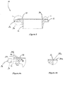
- a flange assembly 10 according to an embodiment of the invention is shown in Figure 1 .
- the flange assembly 10 includes a flange 12 in the form of a disk shaped rim formed on a pipe section 14 for connection to a hose or pipe (not shown).
- the pipe section 14 defines a hollow bore 16 through which flowable material may flow and the flange defines a contact face 18 for engagement, in use, with an opposing flange (not shown).
- the flange 12 defines a gasket seat 20 ( Figure 3 ) about an opening of the bore 16 to receive, in use, a gasket 22 and the flange assembly 10 further includes a gasket clamp to releasably retain the gasket 22 in position on the gasket seat 20.
- the gasket clamp includes first and second opposing gasket clamp members 24a,24b mounted on the contact face 18 of the flange 12.
- the first and second gasket clamp members 24a,24b are located on opposite sides of the opening of the bore 16 and the first gasket clamp member 24a is fixed relative to the contact face 18 of the flange 12.
- the second gasket clamp member 24b however includes an adjustment mechanism 26 to facilitate movement of the second gasket clamp 24b relative to the contact face 18 of the flange 12, towards and away from the gasket seat 20 and the opening of the bore 16.
- each of the first and second gasket clamp members 24a,24b defines a dovetail face 28a,28b to engage against an edge of the gasket 22.
- the downward slope of each dovetail face 28a,28b means that the engagement between each dovetail face 28a,28b and the gasket 22 acts to urge the gasket 22 against the gasket seat 20.
- the adjustment mechanism 26 includes an adjustment screw 30 that is threadedly engaged in an aperture 32 formed in a side face 34 of the flange 12 and drivingly connected to the second gasket clamp member 24b to drive radial movement of the second gasket clamp member 24b relative to the contact face 18 of the flange 12, towards and away from the gasket seat 20.
- an end 36 of the adjustment screw 30 protrudes into an internal cavity 38 formed in the flange 12.
- the end 36 of the adjustment screw 30 is coupled to the second gasket clamp member 24b by means of a link member 40 extending through the cavity 38 and an elongated aperture 42 in the contact face 18 of the flange 12, between the end 36 of the adjustment screw 30 and the second gasket clamp 24b.
- This connection acts to translate radial movement of the adjustment screw 30 relative to the flange 12 into radial movement of the second gasket clamp relative to the contact face 18 of the flange 12, towards and away from the gasket seat 20.
- FIG. 5 The engagement between the end 36 of the adjustment screw 30 and the link member 40 is shown in Figure 5 .
- the link member 40 is fixedly attached at one end to the second gasket clamp member 24b and at its other ends defines a pair of opposed limbs 44a,44b.
- the end 36 of the adjustment screw 30 is received between the opposed limbs 44a,44b, the opposed limbs 44a,44b being received within an annular recess 46 formed about the circumference of the end 36 of the adjustment screw 30, thereby allowing the end 36 of the adjustment screw 30 to rotate relative to the opposed limbs 44a,44b but preventing longitudinal movement of the adjustment screw 30 relative to the opposed limbs 44a,44b in the direction of arrow X.
- rotation of the adjustment screw 30 causes movement into or out of the aperture 32 formed in the flange 12 by virtue of the screw-threaded engagement between the adjustment screw 30 and the aperture 32.
- the nature of the engagement between the end 36 of the adjustment screw 30 and the opposed limbs 44a,44b of the link member 40 means that on rotation of the adjustment screw 30, the second gasket clamp member 24b will be driven towards or away from the gasket seat 20, in the direction of arrow X, depending on the direction of rotation of the adjustment screw 30.
- the second gasket clamp member 24b includes a pair of tenons 46, which are received in corresponding elongated apertures (not shown) in the contact face 18 of the flange 12 to guide movement of the second gasket clamp member 24b.
- a pair of adjustable screws 48 are also provided, which protrude in to corresponding elongated apertures (not shown) in the contact face 18 of the flange 12 so as to form adjustable stops which, in use, limit movement of the second gasket clamp member 24b relative to the contact face 18 of the flange 12.
- the relative positions of these screws 48 may be adjusted to adjust the range of movement of the second gasket clamp member 24b as necessary in order to ensure firm engagement with the gasket 22.
- the flange 12 includes a plurality of through-holes 42 to receive bolts, in use, to secure the contact face 18 of the flange 12 in engagement with an opposing flange.
- the pipe section 14 may be connected to an end connection of a pipe or hose.
- the flange assembly could be used with any existing flange or pipe arrangement and the flange member may, for example, be provided in the form of a short spool flange, a slip on flange, a weld neck flange or a studded flange.
- the flange assembly 10 provides a convenient mechanism for holding a gasket 22 in position on the gasket seat 20 during alignment of the contact face 18 of the flange 12 with an opposing flange. This is particularly advantageous in circumstances where the flange assembly 10 and the opposing flange are connected to opposing ends of a pipe or hose. In the absence of the first and second gasket clamp members 24a,24b the gasket 22 must be held in place by hand, further complicating the alignment and engagement of the flange 12 with an opposing flange, and increasing the risk of injury in the event a hand or fingers become trapped between the flange 12 and the opposing flange.
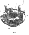
- the flange assembly 10 is particularly advantageous in use with a flange camlock coupler 50, such as that shown in Figure 6 .
- the flange camlock coupler 50 includes a plurality of cam members 52, which may be adjusted to contact and engage the side face 34 of the flange 12 by means of adjustment bolts 54 and thereby secured the flange camlock coupler 50 in position relative to the flange assembly.
- the flange camlock coupler 50 includes four cam members 52. It will be appreciated that in other embodiments the number of cam members 52 may be more or less.
- a guide member 56 is mounted relative to each of the cam members 52, each guide extending generally perpendicularly relative to the contact face 18 of the flange 12 and an uppermost end of each guide member 56 reducing in width so as to define a tapered nose section 58.
- the cam members 52 lock the guide members 56 in position relative to the flange assembly 10 so that an opposing flange (not shown) may then be brought into engagement with the contact face 18 of the flange 12, the guide members 56 serving to guide the flange 12 and the opposing flange into alignment readily with minimum input from an operator and thereby reducing the risk of injury.
- first and second gasket clamp members 24a,24b retain a gasket 22 in position on the gasket seat 20 of the flange 12 and ensure that a complete seal is formed between the flange 12 and the opposing flange once they are aligned.
- a further advantage of the flange camlock coupler 50 is that the guide members 56 maintain the alignment and engagement between the flange 12 and an opposing flange whilst bolts are inserted through the through-holes formed in the flange 12 and the opposing flange to secure the connection.
- a protection ring 60 is also shown, which serves to protect the cam members 52 and the remaining mechanism of the flange camlock coupler 50 during alignment of opposing ends of two pipes. It will be appreciated that such pipes may be significant in size and weight, hence the desire to minimise the risk of damage caused by collisions between component parts and damage caused by trapping hands or fingers therebetween,
Landscapes
- Engineering & Computer Science (AREA)
- General Engineering & Computer Science (AREA)
- Mechanical Engineering (AREA)
- Flanged Joints, Insulating Joints, And Other Joints (AREA)
- Branch Pipes, Bends, And The Like (AREA)
Applications Claiming Priority (1)
| Application Number | Priority Date | Filing Date | Title |
|---|---|---|---|
| GB1120232.2A GB2496872B (en) | 2011-11-23 | 2011-11-23 | Flange assembly |
Publications (3)
| Publication Number | Publication Date |
|---|---|
| EP2597345A2 true EP2597345A2 (de) | 2013-05-29 |
| EP2597345A3 EP2597345A3 (de) | 2017-03-15 |
| EP2597345B1 EP2597345B1 (de) | 2018-12-26 |
Family
ID=45475614
Family Applications (1)
| Application Number | Title | Priority Date | Filing Date |
|---|---|---|---|
| EP12275181.1A Active EP2597345B1 (de) | 2011-11-23 | 2012-11-22 | Flanschanordnung |
Country Status (3)
| Country | Link |
|---|---|
| US (1) | US9366369B2 (de) |
| EP (1) | EP2597345B1 (de) |
| GB (1) | GB2496872B (de) |
Cited By (1)
| Publication number | Priority date | Publication date | Assignee | Title |
|---|---|---|---|---|
| EP3559517A1 (de) * | 2016-12-21 | 2019-10-30 | Forschungszentrum Jülich GmbH | Montagevorrichtung für eine flachdichtung einer flanschverbindung |
Families Citing this family (4)
| Publication number | Priority date | Publication date | Assignee | Title |
|---|---|---|---|---|
| GB2548825A (en) | 2016-03-24 | 2017-10-04 | Magma Global Ltd | Pinned composite pipe end-fitting |
| NO341918B1 (en) * | 2016-05-04 | 2018-02-19 | Cefront Tech As | Offshore loading hose coupling |
| GB2567471B (en) * | 2017-10-13 | 2022-06-08 | Trelleborg Westbury Ltd | Flange assembly |
| GB2592649A (en) | 2020-03-05 | 2021-09-08 | Trelleborg Westbury Ltd | Fluid conduit interlock |
Family Cites Families (8)
| Publication number | Priority date | Publication date | Assignee | Title |
|---|---|---|---|---|
| US2462762A (en) * | 1944-10-19 | 1949-02-22 | Us Gasket Company | Gasket centering means |
| US4168852A (en) * | 1977-06-08 | 1979-09-25 | Vetco, Inc. | Ring gasket retainer for flanged connectors |
| US4168853A (en) * | 1977-06-08 | 1979-09-25 | Vetco, Inc. | Shiftable ring gasket retainer for flanged connectors |
| US4192515A (en) * | 1978-06-05 | 1980-03-11 | Exxon Research & Engineering Co. | Gasket retaining spring |
| US4495689A (en) * | 1983-08-24 | 1985-01-29 | Mcneal Lawrence N | Tool for placement of O-rings and method |
| US5149143A (en) * | 1989-07-20 | 1992-09-22 | National-Oilwell | Connector assembly with detachable sleeve |
| JP2540559Y2 (ja) * | 1991-05-20 | 1997-07-09 | 清原 まさ子 | 管継手用リテーナ |
| TW354821B (en) * | 1996-10-15 | 1999-03-21 | Tadahiro Omi | Fluid coupling |
-
2011
- 2011-11-23 GB GB1120232.2A patent/GB2496872B/en not_active Expired - Fee Related
-
2012
- 2012-11-21 US US13/683,728 patent/US9366369B2/en active Active
- 2012-11-22 EP EP12275181.1A patent/EP2597345B1/de active Active
Cited By (1)
| Publication number | Priority date | Publication date | Assignee | Title |
|---|---|---|---|---|
| EP3559517A1 (de) * | 2016-12-21 | 2019-10-30 | Forschungszentrum Jülich GmbH | Montagevorrichtung für eine flachdichtung einer flanschverbindung |
Also Published As
| Publication number | Publication date |
|---|---|
| EP2597345B1 (de) | 2018-12-26 |
| GB201120232D0 (en) | 2012-01-04 |
| EP2597345A3 (de) | 2017-03-15 |
| GB2496872A (en) | 2013-05-29 |
| US9366369B2 (en) | 2016-06-14 |
| GB2496872B (en) | 2015-09-23 |
| US20130147190A1 (en) | 2013-06-13 |
Similar Documents
| Publication | Publication Date | Title |
|---|---|---|
| EP2597345A2 (de) | Flanschanordnung | |
| US20160201806A1 (en) | Diaphragm air seal | |
| US10836581B2 (en) | Infeed and outfeed assemblies for a conveyor | |
| US10018295B2 (en) | Boring device | |
| US20100058563A1 (en) | Clamp Securement | |
| WO2016076999A1 (en) | Flange gasket installation apparatus and method | |
| IL209936A (en) | Assembled handle with handle | |
| EP3696446B1 (de) | Keilklemme und stahldraht | |
| EP2805093B1 (de) | Verbesserte vorrichtung und verfahren zum einfügen von dichtungen | |
| EP3122947B1 (de) | Werkzeug und verfahren zur installation/entfernung eines haltebolzens | |
| US10088077B2 (en) | Apparatus and methods for insertion of gaskets | |
| EP3470722A2 (de) | Flanschanordnung | |
| EP2805793B1 (de) | Stützvorrichtung für einen führungsrahmen | |
| US9568032B2 (en) | Wedge clamp for securing safety guards around industrial equipment | |
| EP2941331B1 (de) | Verbesserte vorrichtung und verfahren zum einfügen von dichtungen | |
| EP1954886B1 (de) | Zentriervorrichtung für schnellwechselvorrichtungen | |
| WO2019014556A1 (en) | Container clamp assembly | |
| JP2016010833A (ja) | 回転工具 | |
| EP3068584B1 (de) | Verbesserte vorrichtungen und verfahren zum einsetzen von dichtungen | |
| US9574330B2 (en) | Retention system for a wear member | |
| EP2891543A1 (de) | Hilfsvorrichtung zum Greifen und Verschrauben eines ersten Bauteils, das eine Leitung umfasst, mit einem zweiten Bauteil und Zusammenstellungsverfahren | |
| KR20200043738A (ko) | U볼트용 커버 | |
| CN109573477A (zh) | 一种输送带的调节装置 | |
| GB2577266A (en) | Nozzle assembly | |
| GB1601477A (en) | Locking arrangement particularly for shackles |
Legal Events
| Date | Code | Title | Description |
|---|---|---|---|
| PUAI | Public reference made under article 153(3) epc to a published international application that has entered the european phase |
Free format text: ORIGINAL CODE: 0009012 |
|
| AK | Designated contracting states |
Kind code of ref document: A2 Designated state(s): AL AT BE BG CH CY CZ DE DK EE ES FI FR GB GR HR HU IE IS IT LI LT LU LV MC MK MT NL NO PL PT RO RS SE SI SK SM TR |
|
| AX | Request for extension of the european patent |
Extension state: BA ME |
|
| PUAL | Search report despatched |
Free format text: ORIGINAL CODE: 0009013 |
|
| AK | Designated contracting states |
Kind code of ref document: A3 Designated state(s): AL AT BE BG CH CY CZ DE DK EE ES FI FR GB GR HR HU IE IS IT LI LT LU LV MC MK MT NL NO PL PT RO RS SE SI SK SM TR |
|
| AX | Request for extension of the european patent |
Extension state: BA ME |
|
| RIC1 | Information provided on ipc code assigned before grant |
Ipc: F16L 23/18 20060101AFI20170206BHEP Ipc: F16L 23/00 20060101ALI20170206BHEP Ipc: F16L 23/02 20060101ALI20170206BHEP Ipc: F16L 23/16 20060101ALI20170206BHEP |
|
| STAA | Information on the status of an ep patent application or granted ep patent |
Free format text: STATUS: REQUEST FOR EXAMINATION WAS MADE |
|
| 17P | Request for examination filed |
Effective date: 20170519 |
|
| RBV | Designated contracting states (corrected) |
Designated state(s): AL AT BE BG CH CY CZ DE DK EE ES FI FR GB GR HR HU IE IS IT LI LT LU LV MC MK MT NL NO PL PT RO RS SE SI SK SM TR |
|
| GRAP | Despatch of communication of intention to grant a patent |
Free format text: ORIGINAL CODE: EPIDOSNIGR1 |
|
| STAA | Information on the status of an ep patent application or granted ep patent |
Free format text: STATUS: GRANT OF PATENT IS INTENDED |
|
| INTG | Intention to grant announced |
Effective date: 20180612 |
|
| RIN1 | Information on inventor provided before grant (corrected) |
Inventor name: WILLIAMSON, MARK |
|
| GRAS | Grant fee paid |
Free format text: ORIGINAL CODE: EPIDOSNIGR3 |
|
| GRAA | (expected) grant |
Free format text: ORIGINAL CODE: 0009210 |
|
| STAA | Information on the status of an ep patent application or granted ep patent |
Free format text: STATUS: THE PATENT HAS BEEN GRANTED |
|
| AK | Designated contracting states |
Kind code of ref document: B1 Designated state(s): AL AT BE BG CH CY CZ DE DK EE ES FI FR GB GR HR HU IE IS IT LI LT LU LV MC MK MT NL NO PL PT RO RS SE SI SK SM TR |
|
| REG | Reference to a national code |
Ref country code: GB Ref legal event code: FG4D |
|
| REG | Reference to a national code |
Ref country code: CH Ref legal event code: EP |
|
| REG | Reference to a national code |
Ref country code: AT Ref legal event code: REF Ref document number: 1081880 Country of ref document: AT Kind code of ref document: T Effective date: 20190115 |
|
| REG | Reference to a national code |
Ref country code: IE Ref legal event code: FG4D |
|
| REG | Reference to a national code |
Ref country code: DE Ref legal event code: R096 Ref document number: 602012055076 Country of ref document: DE |
|
| REG | Reference to a national code |
Ref country code: SE Ref legal event code: TRGR |
|
| PG25 | Lapsed in a contracting state [announced via postgrant information from national office to epo] |
Ref country code: LV Free format text: LAPSE BECAUSE OF FAILURE TO SUBMIT A TRANSLATION OF THE DESCRIPTION OR TO PAY THE FEE WITHIN THE PRESCRIBED TIME-LIMIT Effective date: 20181226 Ref country code: FI Free format text: LAPSE BECAUSE OF FAILURE TO SUBMIT A TRANSLATION OF THE DESCRIPTION OR TO PAY THE FEE WITHIN THE PRESCRIBED TIME-LIMIT Effective date: 20181226 Ref country code: NO Free format text: LAPSE BECAUSE OF FAILURE TO SUBMIT A TRANSLATION OF THE DESCRIPTION OR TO PAY THE FEE WITHIN THE PRESCRIBED TIME-LIMIT Effective date: 20190326 Ref country code: BG Free format text: LAPSE BECAUSE OF FAILURE TO SUBMIT A TRANSLATION OF THE DESCRIPTION OR TO PAY THE FEE WITHIN THE PRESCRIBED TIME-LIMIT Effective date: 20190326 Ref country code: LT Free format text: LAPSE BECAUSE OF FAILURE TO SUBMIT A TRANSLATION OF THE DESCRIPTION OR TO PAY THE FEE WITHIN THE PRESCRIBED TIME-LIMIT Effective date: 20181226 Ref country code: HR Free format text: LAPSE BECAUSE OF FAILURE TO SUBMIT A TRANSLATION OF THE DESCRIPTION OR TO PAY THE FEE WITHIN THE PRESCRIBED TIME-LIMIT Effective date: 20181226 |
|
| REG | Reference to a national code |
Ref country code: NL Ref legal event code: MP Effective date: 20181226 |
|
| REG | Reference to a national code |
Ref country code: LT Ref legal event code: MG4D |
|
| PG25 | Lapsed in a contracting state [announced via postgrant information from national office to epo] |
Ref country code: GR Free format text: LAPSE BECAUSE OF FAILURE TO SUBMIT A TRANSLATION OF THE DESCRIPTION OR TO PAY THE FEE WITHIN THE PRESCRIBED TIME-LIMIT Effective date: 20190327 Ref country code: AL Free format text: LAPSE BECAUSE OF FAILURE TO SUBMIT A TRANSLATION OF THE DESCRIPTION OR TO PAY THE FEE WITHIN THE PRESCRIBED TIME-LIMIT Effective date: 20181226 Ref country code: RS Free format text: LAPSE BECAUSE OF FAILURE TO SUBMIT A TRANSLATION OF THE DESCRIPTION OR TO PAY THE FEE WITHIN THE PRESCRIBED TIME-LIMIT Effective date: 20181226 |
|
| REG | Reference to a national code |
Ref country code: AT Ref legal event code: MK05 Ref document number: 1081880 Country of ref document: AT Kind code of ref document: T Effective date: 20181226 |
|
| PG25 | Lapsed in a contracting state [announced via postgrant information from national office to epo] |
Ref country code: NL Free format text: LAPSE BECAUSE OF FAILURE TO SUBMIT A TRANSLATION OF THE DESCRIPTION OR TO PAY THE FEE WITHIN THE PRESCRIBED TIME-LIMIT Effective date: 20181226 |
|
| PG25 | Lapsed in a contracting state [announced via postgrant information from national office to epo] |
Ref country code: PT Free format text: LAPSE BECAUSE OF FAILURE TO SUBMIT A TRANSLATION OF THE DESCRIPTION OR TO PAY THE FEE WITHIN THE PRESCRIBED TIME-LIMIT Effective date: 20190426 Ref country code: CZ Free format text: LAPSE BECAUSE OF FAILURE TO SUBMIT A TRANSLATION OF THE DESCRIPTION OR TO PAY THE FEE WITHIN THE PRESCRIBED TIME-LIMIT Effective date: 20181226 Ref country code: PL Free format text: LAPSE BECAUSE OF FAILURE TO SUBMIT A TRANSLATION OF THE DESCRIPTION OR TO PAY THE FEE WITHIN THE PRESCRIBED TIME-LIMIT Effective date: 20181226 Ref country code: ES Free format text: LAPSE BECAUSE OF FAILURE TO SUBMIT A TRANSLATION OF THE DESCRIPTION OR TO PAY THE FEE WITHIN THE PRESCRIBED TIME-LIMIT Effective date: 20181226 |
|
| PG25 | Lapsed in a contracting state [announced via postgrant information from national office to epo] |
Ref country code: IS Free format text: LAPSE BECAUSE OF FAILURE TO SUBMIT A TRANSLATION OF THE DESCRIPTION OR TO PAY THE FEE WITHIN THE PRESCRIBED TIME-LIMIT Effective date: 20190426 Ref country code: RO Free format text: LAPSE BECAUSE OF FAILURE TO SUBMIT A TRANSLATION OF THE DESCRIPTION OR TO PAY THE FEE WITHIN THE PRESCRIBED TIME-LIMIT Effective date: 20181226 Ref country code: SK Free format text: LAPSE BECAUSE OF FAILURE TO SUBMIT A TRANSLATION OF THE DESCRIPTION OR TO PAY THE FEE WITHIN THE PRESCRIBED TIME-LIMIT Effective date: 20181226 Ref country code: EE Free format text: LAPSE BECAUSE OF FAILURE TO SUBMIT A TRANSLATION OF THE DESCRIPTION OR TO PAY THE FEE WITHIN THE PRESCRIBED TIME-LIMIT Effective date: 20181226 Ref country code: SM Free format text: LAPSE BECAUSE OF FAILURE TO SUBMIT A TRANSLATION OF THE DESCRIPTION OR TO PAY THE FEE WITHIN THE PRESCRIBED TIME-LIMIT Effective date: 20181226 |
|
| REG | Reference to a national code |
Ref country code: DE Ref legal event code: R097 Ref document number: 602012055076 Country of ref document: DE |
|
| PG25 | Lapsed in a contracting state [announced via postgrant information from national office to epo] |
Ref country code: AT Free format text: LAPSE BECAUSE OF FAILURE TO SUBMIT A TRANSLATION OF THE DESCRIPTION OR TO PAY THE FEE WITHIN THE PRESCRIBED TIME-LIMIT Effective date: 20181226 Ref country code: DK Free format text: LAPSE BECAUSE OF FAILURE TO SUBMIT A TRANSLATION OF THE DESCRIPTION OR TO PAY THE FEE WITHIN THE PRESCRIBED TIME-LIMIT Effective date: 20181226 |
|
| PLBE | No opposition filed within time limit |
Free format text: ORIGINAL CODE: 0009261 |
|
| STAA | Information on the status of an ep patent application or granted ep patent |
Free format text: STATUS: NO OPPOSITION FILED WITHIN TIME LIMIT |
|
| 26N | No opposition filed |
Effective date: 20190927 |
|
| PG25 | Lapsed in a contracting state [announced via postgrant information from national office to epo] |
Ref country code: SI Free format text: LAPSE BECAUSE OF FAILURE TO SUBMIT A TRANSLATION OF THE DESCRIPTION OR TO PAY THE FEE WITHIN THE PRESCRIBED TIME-LIMIT Effective date: 20181226 |
|
| PG25 | Lapsed in a contracting state [announced via postgrant information from national office to epo] |
Ref country code: TR Free format text: LAPSE BECAUSE OF FAILURE TO SUBMIT A TRANSLATION OF THE DESCRIPTION OR TO PAY THE FEE WITHIN THE PRESCRIBED TIME-LIMIT Effective date: 20181226 |
|
| REG | Reference to a national code |
Ref country code: CH Ref legal event code: PL |
|
| PG25 | Lapsed in a contracting state [announced via postgrant information from national office to epo] |
Ref country code: CH Free format text: LAPSE BECAUSE OF NON-PAYMENT OF DUE FEES Effective date: 20191130 Ref country code: MC Free format text: LAPSE BECAUSE OF FAILURE TO SUBMIT A TRANSLATION OF THE DESCRIPTION OR TO PAY THE FEE WITHIN THE PRESCRIBED TIME-LIMIT Effective date: 20181226 Ref country code: LI Free format text: LAPSE BECAUSE OF NON-PAYMENT OF DUE FEES Effective date: 20191130 Ref country code: LU Free format text: LAPSE BECAUSE OF NON-PAYMENT OF DUE FEES Effective date: 20191122 |
|
| REG | Reference to a national code |
Ref country code: BE Ref legal event code: MM Effective date: 20191130 |
|
| PG25 | Lapsed in a contracting state [announced via postgrant information from national office to epo] |
Ref country code: IE Free format text: LAPSE BECAUSE OF NON-PAYMENT OF DUE FEES Effective date: 20191122 |
|
| PG25 | Lapsed in a contracting state [announced via postgrant information from national office to epo] |
Ref country code: BE Free format text: LAPSE BECAUSE OF NON-PAYMENT OF DUE FEES Effective date: 20191130 |
|
| PG25 | Lapsed in a contracting state [announced via postgrant information from national office to epo] |
Ref country code: CY Free format text: LAPSE BECAUSE OF FAILURE TO SUBMIT A TRANSLATION OF THE DESCRIPTION OR TO PAY THE FEE WITHIN THE PRESCRIBED TIME-LIMIT Effective date: 20181226 |
|
| PG25 | Lapsed in a contracting state [announced via postgrant information from national office to epo] |
Ref country code: HU Free format text: LAPSE BECAUSE OF FAILURE TO SUBMIT A TRANSLATION OF THE DESCRIPTION OR TO PAY THE FEE WITHIN THE PRESCRIBED TIME-LIMIT; INVALID AB INITIO Effective date: 20121122 Ref country code: MT Free format text: LAPSE BECAUSE OF FAILURE TO SUBMIT A TRANSLATION OF THE DESCRIPTION OR TO PAY THE FEE WITHIN THE PRESCRIBED TIME-LIMIT Effective date: 20181226 |
|
| REG | Reference to a national code |
Ref country code: DE Ref legal event code: R081 Ref document number: 602012055076 Country of ref document: DE Owner name: TRELLEBORG WESTBURY LIMITED, GB Free format text: FORMER OWNER: KLAW PRODUCTS LTD., WESTBURY, WILTSHIRE, GB |
|
| PG25 | Lapsed in a contracting state [announced via postgrant information from national office to epo] |
Ref country code: MK Free format text: LAPSE BECAUSE OF FAILURE TO SUBMIT A TRANSLATION OF THE DESCRIPTION OR TO PAY THE FEE WITHIN THE PRESCRIBED TIME-LIMIT Effective date: 20181226 |
|
| P01 | Opt-out of the competence of the unified patent court (upc) registered |
Effective date: 20230417 |
|
| PGFP | Annual fee paid to national office [announced via postgrant information from national office to epo] |
Ref country code: DE Payment date: 20251125 Year of fee payment: 14 |
|
| PGFP | Annual fee paid to national office [announced via postgrant information from national office to epo] |
Ref country code: GB Payment date: 20251110 Year of fee payment: 14 |
|
| PGFP | Annual fee paid to national office [announced via postgrant information from national office to epo] |
Ref country code: IT Payment date: 20251112 Year of fee payment: 14 |
|
| PGFP | Annual fee paid to national office [announced via postgrant information from national office to epo] |
Ref country code: FR Payment date: 20251126 Year of fee payment: 14 |
|
| PGFP | Annual fee paid to national office [announced via postgrant information from national office to epo] |
Ref country code: SE Payment date: 20251110 Year of fee payment: 14 |