EP2597252A2 - System zum Testen von Bohrlöchern mit kompakter Oberfläche und Verfahren - Google Patents
System zum Testen von Bohrlöchern mit kompakter Oberfläche und Verfahren Download PDFInfo
- Publication number
- EP2597252A2 EP2597252A2 EP12172359.7A EP12172359A EP2597252A2 EP 2597252 A2 EP2597252 A2 EP 2597252A2 EP 12172359 A EP12172359 A EP 12172359A EP 2597252 A2 EP2597252 A2 EP 2597252A2
- Authority
- EP
- European Patent Office
- Prior art keywords
- frame
- separator
- module
- surge tank
- testing system
- Prior art date
- Legal status (The legal status is an assumption and is not a legal conclusion. Google has not performed a legal analysis and makes no representation as to the accuracy of the status listed.)
- Withdrawn
Links
Images








Classifications
-
- E—FIXED CONSTRUCTIONS
- E21—EARTH OR ROCK DRILLING; MINING
- E21B—EARTH OR ROCK DRILLING; OBTAINING OIL, GAS, WATER, SOLUBLE OR MELTABLE MATERIALS OR A SLURRY OF MINERALS FROM WELLS
- E21B43/00—Methods or apparatus for obtaining oil, gas, water, soluble or meltable materials or a slurry of minerals from wells
- E21B43/34—Arrangements for separating materials produced by the well
-
- E—FIXED CONSTRUCTIONS
- E21—EARTH OR ROCK DRILLING; MINING
- E21B—EARTH OR ROCK DRILLING; OBTAINING OIL, GAS, WATER, SOLUBLE OR MELTABLE MATERIALS OR A SLURRY OF MINERALS FROM WELLS
- E21B43/00—Methods or apparatus for obtaining oil, gas, water, soluble or meltable materials or a slurry of minerals from wells
- E21B43/25—Methods for stimulating production
- E21B43/26—Methods for stimulating production by forming crevices or fractures
- E21B43/2607—Surface equipment specially adapted for fracturing operations
-
- E—FIXED CONSTRUCTIONS
- E21—EARTH OR ROCK DRILLING; MINING
- E21B—EARTH OR ROCK DRILLING; OBTAINING OIL, GAS, WATER, SOLUBLE OR MELTABLE MATERIALS OR A SLURRY OF MINERALS FROM WELLS
- E21B49/00—Testing the nature of borehole walls; Formation testing; Methods or apparatus for obtaining samples of soil or well fluids, specially adapted to earth drilling or wells
-
- Y—GENERAL TAGGING OF NEW TECHNOLOGICAL DEVELOPMENTS; GENERAL TAGGING OF CROSS-SECTIONAL TECHNOLOGIES SPANNING OVER SEVERAL SECTIONS OF THE IPC; TECHNICAL SUBJECTS COVERED BY FORMER USPC CROSS-REFERENCE ART COLLECTIONS [XRACs] AND DIGESTS
- Y10—TECHNICAL SUBJECTS COVERED BY FORMER USPC
- Y10T—TECHNICAL SUBJECTS COVERED BY FORMER US CLASSIFICATION
- Y10T29/00—Metal working
- Y10T29/49—Method of mechanical manufacture
- Y10T29/49826—Assembling or joining
- Y10T29/49947—Assembling or joining by applying separate fastener
- Y10T29/49959—Nonresilient fastener
Definitions
- the invention relates to well testing systems, and methods therefor.
- Surface well testing provides information about reservoir extent, productivity, fluid properties, composition, flow, pressure, temperature, and others.
- the main objectives of surface well testing are to measure the volumetric flow-rate of individual phases, obtain samples and determine characteristics of the main fluids (e.g., water, oil, and gas), and solids.
- the surface testing equipment must perform a wide range of functions, including: control pressure and flow rates at the surface and shut in the well; accurately meter the fluids and collect surface fluid samples; and separate the resulting effluent into three fluids: oil, gas, water, and solids.
- a well testing system comprises a number of modules.
- a first module includes a separator frame configured to receive a separator and/or a steam-heat exchanger.
- a second module includes a fluid storage i.e. surge tank frame including a surge tank front frame, wherein the surge tank frame is configured to receive at least two surge tanks.
- a third module includes a compact flow control i.e. manifold comprising oil, gas and water manifolds; oil and water transfer pumps. At least one of the separator frame, the separator, the steam-heat exchanger, the surge tank frame, and the surge tanks interconnects with another apparatus (i.e., element) of the group through one or more clamps.
- a method comprises constructing a well testing system.
- the method includes placing a separator frame on a deck.
- the method further includes placing a first guiding, stopping and/or fixing clamp on the separator frame.
- the method further includes placing a separator on the separator frame using the first guiding, stopping and/or fixing clamp.
- the method further includes placing a modular surge tank frame and a modular surge tank front frame, and assembling the modular surge tank frame and the modular surge tank front frame to obtain a surge tank frame.
- the method includes placing a second guiding, stopping and/or fixing clamps on the surge tank frame and placing two surge tanks on the surge tank frame using the third guiding, stopping and/or fixing clamps.
- the method includes placing a compact manifold on the deck.
- the method further includes interconnecting the separator frame with the surge tank frame and the compact manifold. This method also includes the connection of all modules as a unique compact arrangement or as a distributed arrangement in order to adapt to different deck spaces in the offshore units.
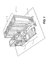
- FIG. 1 illustrates a well testing system in accordance with one or more embodiments disclosed herein;
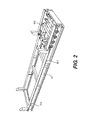
- FIG. 2 illustrates a modular separator frame in accordance with one or more embodiments disclosed herein;
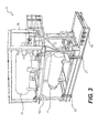
- FIG. 3 illustrates a separator and a steam-heat exchanger assembly in accordance with one or more embodiments disclosed herein;
- FIG. 4A-4G illustrate guiding and fixing clamps in accordance with embodiments disclosed herein;
- FIG. 5 illustrates a modular surge tank frame in accordance with embodiments disclosed herein
- FIG. 6 illustrates a surge tank front frame in accordance with one or more embodiments disclosed herein;
- FIG. 7 depicts a surge tank clamp in accordance with one or more embodiments disclosed herein;
- FIG. 8 depicts a surge tank module in accordance with one or more embodiments disclosed herein;
- FIG. 9 depicts a manifold module in accordance with one or more embodiments disclosed herein;
- FIG. 10 depicts a modular separator frame fixed on deck in accordance with one or more embodiments disclosed herein;
- FIG. 11 depicts a modular separator frame with clamps in accordance with one or more embodiments disclosed herein;
- FIG. 12 illustrates a modular separator frame with the separator in accordance with one or more embodiments disclosed herein;
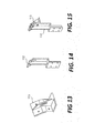
- FIGS. 13-15 illustrate guiding and fixing clamps for the modular separator frame in accordance with one or more embodiments disclosed herein;
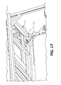
- FIGS. 16 and 17 illustrate a modular separator frame with the separator in accordance with one or more embodiments disclosed herein;
- FIG. 18 depicts a modular separator frame with the separator and the steam-heat exchanger in accordance with one or more embodiments disclosed herein;
- FIG. 19 depicts intermediate spools with the separator and steam-heat exchanger module in accordance with one or more embodiments disclosed herein;
- FIG. 20 depicts the separator and steam-heat exchanger module with the compact manifold module in accordance with one or more embodiments disclosed herein;
- FIGS. 21 and 22 depict a compact manifold module in accordance with one or more embodiments disclosed herein;
- FIG. 23 depicts a detail of the attachment of the modular surge tank frame and the modular surge tank front in accordance with one or more embodiments disclosed herein;
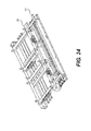
- FIG. 24 depicts a modular surge tank frame and a modular surge tank front frame in accordance with one or more embodiments disclosed herein;
- FIG. 25 depicts a surge tank frame and surge tanks in accordance with one or more embodiments disclosed herein.
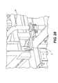
- FIGS. 26-28 depict surge tank frame and surge tank placement in accordance with one or more embodiments disclosed herein.
- transitional phrases “including,” “comprising,” “having,” “containing,” or “involving,” and variations thereof is intended to be broad and encompass a composition, a group of elements, a process or method steps, or any other expression listed thereafter, as well as equivalents, and additional subject matter not recited. Further, the transitional phrases “comprising,” “including,” or “containing,” are intended to encompass narrow language, such as the transitional phrases “consisting essentially of,” “consisting, of,” or “selected from the group of consisting of,” preceding the recitation of the composition, the group of elements, the process or the method steps or any other expression.
- the disclosed embodiments relate to modular well testing systems, and methods therefor. More specifically, the embodiments are directed to a well testing system adapted to be modular, compact, mobile, and/or flexible in its assembly and arrangement.
- the disclosed surface well testing system reduces rig space, installation time, de-installation time, equipment volume and access and difficulty of moving heavy equipment and piping. Further, aspects of the disclosed embodiments decrease the risk of injury of the personnel involved in this activity.
- embodiments of the disclosed well testing system have a maximum deck load of about two (2.0) tons per square meter.
- embodiments of the disclosed well testing system take about 14 meters by 6.5 meters of deck area having a unique or distributed arrangement.
- the disclosed well testing system can be rigged up by about three people in about three days, whereas conventional systems can requires about ten people and about ten days.
- FIG. 1 shows a modular well testing system 1 in accordance with embodiments disclosed herein.
- the well testing system 1 includes a separator-exchanger module 3, a fluid storage module 5, and a flow-control module 7.
- the fluid storage is a surge tank and the flow-control is a manifold.
- one or more of the modules 3, 5 and 7 are interconnected using various guiding, stopping, and fixing clamps.
- the well testing system can be securely attached to a deck 9 of, for example, a drilling rig in a configuration having a compact and unique arrangement.
- the separator-exchanger module 3 includes a separator frame, a separator and/or a steam-heat exchanger.
- FIG. 2 shows a separator frame 10 in accordance with embodiments disclosed herein.
- the separator frame 10 is a unit adapted to support the weight of heavy equipment.
- the separator frame 10 is comprised of structural beams sufficient to bear the weight of the separator 11 and the steam-heat exchanger 12 ( FIG. 3 ), one stacked above the other.
- the separator frame equipment may be certified according to a DNV lifting certification (DNV 2.7-3 Type 2 Certified).
- the structural beams of the separator frame 10 have pre-fabricated locations 101 for attaching guiding and stopping clamps ( FIG. 4A ).
- the separator frame 10 also includes pipes 102 and/or portions thereof, which can connect the frame to other modules of the well test system 1, including the separator 11, and the manifold module 7.
- the separator frame 10 includes at least five pipes for supplying fluids in or out of the separator 11 after assembly of the well test system.
- the pipes 102 can be marked to indicate the fluid to be passed through them.
- the pipes 102 are also positioned securely on the separator frame 10 to enable connection with the corresponding pipes of, for example, the separator 11 and the manifold module 7.
- FIG. 3 shows the separator 11 and the steam-heat exchanger 12 mounted on the separator frame 10 in accordance with embodiments disclosed herein.
- the illustrated assembly also depicts corresponding access system stairs, walkways and handrails.
- the separator 11 and the steam-heat exchanger 12 are modules configured to stack on top of the separator frame 10. More specifically, the separator 11 and the steam-heat exchanger 12 are surrounded by respective structural frames 14 and 15 that support these elements in the well test system 1 and allow them to be easily picked-up, moved, and stacked, as additionally described with respect to FIGS. 12 and 13 .
- the separator 11 separates the well effluent into three main fluids (gas, oil, and water) and solids to enable these fluids to be individually measured and directed for collection, burning/flaring, or controlled disposal, depending on a particular test application.
- the steam-heat exchanger 12 is used to raise the temperature of well effluents to prevent hydrate formation, reduce viscosity, break down emulsions for efficient separation of oil and water and also increase the burning efficiency.
- the separator 11 and steam-heat exchanger 12 can be mounted in a stacked arrangement on the modular separator frame 10, as illustrated in FIG. 3 , which shows the separator 11 and the steam-heat exchanger 12 assembled into the separator-exchanger module 3. After assembly (e.g., on a rig), a mechanism is provided to avoid the well testing system 1 from sliding and twisting due to movements of a deck (e.g., deck 9). By stacking the separator 11 and the steam-heat exchanger 12, the amount of area on the surface of a drill rig is reduced in comparison to conventional systems. While FIG 3 illustrates the steam-heat exchanger 12 stacked on top of the separator 11, these structures are modular, and, as such, it is contemplated in some embodiments stacking the separator on top of the steam-heat exchanger 12.
- FIG. 4A shows a guiding and stopping clamp 21 in accordance with embodiments disclosed herein.
- These clamps have the function of guiding the modules (including, e.g., the separator 11 and the steam-heat exchanger 12) at the time of assembly, and precisely stopping the modules at particular positions of the well testing system 1. Further, the use of these clamps to precisely position the modules and their components enables the usage of pre-manufactured spools with specific dimensions (e.g., the dimensions of prefabricated spools) that align with piping (e.g., pipes 102) in the modules. As such, the time and labor used to interconnect the well test system 1 is reduced.
- the guiding and stopping clamp 21 positions the separator 11 on the separator structure frame 10. Additionally or alternatively, the guiding and stopping clamp 21 can be attached to the modular separator frame 10 at predetermined locations, such as locations 101 depicted in FIG. 2 , to prevent twisting of the assembled well testing system 1 due to movements of a rig (e.g., to wind and/or waves).
- FIG. 3 . FIG. 4B shows the fixing clamp 22, in accordance with embodiments disclosed herein. In embodiments, the fixing clamp 22 prevents twisting of the separator-exchanger module 3.
- FIG. 4C shows the guiding and stopping clamp 21 and the fixing clamp 22 connected to a top guiding clamp 23, in accordance with embodiments disclosed herein.
- the guiding and stopping clamp 21, the fixing clamp 22 can be connected to the top guiding clamp 23 using conventional methods (e.g., welding, bolting, riveting).
- the top guiding clamp 23 attaches the stopping clamp 21 and the fixing claim 22 to the top of the separator 11 and is used to place the steam-heat exchanger 12 in alignment with the separator module 11.
- the top guiding clamp 23 includes an eye hole 24 on its lower surface through which the top guiding clamp can be securely pinned to a pad eye of a separator frame. ( FIG. 17 .)
- Figures 4D to 4F show exemplary clamps configured to be connected to the deck of a rig.
- the clamp 201 is connected (e.g., by welding, bolting or riveting) to a deck (e.g., deck 9).
- a number of clamps 201 can be attached to hard points on a rig's deck.
- a clamp 202 grips a flange of a frame (e.g., separator frame 10) after tightly securing clamp 201 on clamp 202, e.g., using bolts, as shown in FIG. 4F .
- FIG. 4G shows a guiding clamp 112.
- the guiding clamp 112 positions the separator 11 on the separator structure frame 10. Additionally or alternatively, the guiding clamp 112 can be attached to the modular separator frame 10 at predetermined locations, such as locations 101 in FIG. 2 , to prevent twisting of the to prevent twisting of the assembled well testing system 1 due to movements of a rig (e.g., to wind and/or waves).
- a rig e.g., to wind and/or waves
- the surge tank module 5 can include a surge tank frame and a surge tank front frame and vertical surge tanks.
- FIG. 5 shows an exemplary surge tank frame 30 that can be used in the surge tank module 5.
- the surge tank frame 30 is comprised of structural beams having sufficient strength to support at least two surge tanks and their contents. Similar to the separator frame 10, the structural beams of the surge tank frame 30 can have pre-fabricated locations for affixing guiding and stopping clamps 21 and fixing clamps 22 to guide vertical surge tanks to predetermined positions on the surge tank frame 30, such that they are aligned at the positions and fixed securely in place.
- the surge tank frame 30 is configured to support the weight of two vertical surge tanks and distribute the weight over an area of the deck 9. Further, as shown in FIG. 5 , the surge tank frame 30 can include pre-installed pipework providing fluid connections between to the surge tank module 5 and other modules of the well testing system 1, including the separator-exchanger module 3 and/or the manifold module 7.
- FIG. 6 shows a surge tank front frame 51 in accordance with embodiments disclosed herein.
- the surge tank front frame 51 can be used as part of the pipework that is conventionally installed after assembly of a rig.
- the surge tank front frame 51 may be comprised of structural beams.
- the surge tank front frame 51 can be attached to the surge tank frame 30 shown in FIG. 5 to spread the weight of the surge tanks, thereby decreasing the load placed on the deck of a rig (e.g., deck 9).
- the equipment may include a DNV lifting certification (e.g., a DNV 2.7-3 Type 2 certification).
- the surge tank front frame 51 can include pre-installed pipework providing fluid connections between the surge tank module 5 and other modules of the well testing system 1, including the separator-exchanger module 3 and/or the manifold module 7.
- FIG. 7 shows a surge tank clamp 41 in accordance with aspects of the disclosed embodiments.
- the surge tank clamp 41 can be used in the surge tank module 5 to guide and securely attach the surge tank frame structure 33 to the surge tank frame 30.
- FIG. 8 The surge tank clamp 41 prevents the surge tanks and/or their respective frames from twisting due, for example, to movement of the deck 9.
- one or more of the fixing clamps 22 can be securely attached to the surge tank frame 30 and to the frame structure 33 to prevent the surge tanks from moving and/or twisting due to, for example, movement of a rig.
- the equipment may include a DNV lifting certification (DNV 2.7-3 Type 2 Certified).
- FIG. 8 shows exemplary surge tanks 31 and 32 mounted on the surge tank frame 30 to be used in in the surge tank module 5.
- the surge tanks 31 and 32 are used to store liquids produced during well testing, for example, prior to disposal. Additionally or alternatively, the surge tanks 31 and 32 are used as an additional stage of separation and metering.
- FIG. 8 shows an exemplary surge tank module 5 in accordance with embodiments disclosed herein.
- the surge tank module 5 is composed of the surge tank frame 30, the vertical surge tanks 31 and 32, and the surge tank front frame 51. These elements can be connected to each other with, for example, screws or some other attachment mechanism.
- each of vertical surge tanks 31, 32 is securely positioned inside a frame structure 33, as shown in FIG. 8 that supports these elements in the well test system 1 and allows them to be easily picked-up, moved, and stacked.
- the modular surge tanks 31, 32 with their frame 33 can be positioned using a lifting device on top of the modular surge tank frame 30.
- the well testing system 1 can include one or more additional surge tank modules 5 by securely attaching one beside the other on, for example, the deck 9, as shown in FIG. 1 . Therefore, the well testing system 1 may readily accommodate more than two surge tanks by easily adding additional surge tank modules to allow for 4 or more surge tanks to handle the fluid disposal needs of the well test design.
- the modular and compact configuration of the surge tank module 5 (together with the manifold module 3) can be readily be adjusted to accommodate different effluent flow rates, and thereby offers flexibility for the compact well system enabling to successfully serve the well test design needs of different wells.
- the manifold module 7 includes a compact manifold.
- FIG. 9 shows an exemplary compact manifold 60.
- the compact manifold 60 is an arrangement of piping, valves and oil and water pumps configured to control, distribute and monitor fluid flow in the well testing system 1.
- the compact manifold 60 combines many of the functionalities of between 6 to 10 pieces of conventional equipment.
- the compact manifold 60 can include pre-installed pipework providing fluid connections between the manifold module 7, the separator-exchanger module 3 and/or the surge tank module 5.
- the compact manifold 60 includes four pumping units being two air driven pumps and two electrical pumps with their respective control panels 64 and 65.
- the compact manifold 60 includes a plurality of pipes providing one or more pathways to transfer the well effluent to the separator 11. Additionally or alternatively, embodiments of the compact manifold 60 direct fluids to various equipment and flow lines, and to circulate the fluid between tanks 31 and 32. ( FIG. 22 .)
- one or more fluid pathways can include valve mechanisms for controlling the flow of the effluent before it reaches the separator 11.
- the compact manifold 60 can include a DNV lifting certification (DNV 2.7-1 Certified).
- the separator-exchanger module 3 is rigged up in the sequence described below.
- the modular separator frame 10 is placed at a desired position at the deck 9.
- the separator frame 10 can be securely fixed to the deck 9 (e.g., at hard points 92) using brackets 201 and 202 detailed, for example, in FIGS. 4D and 4E .
- the guiding clamps 21 and/or 112 are attached to the side of the separator frame 10 using fastening mechanism, such as screws.
- the guiding clamps 21 and/or 112 are positioned at the pre-fabricated locations 101 1 found on the structural beams comprising the separator frame 10.
- the two different types of guiding clamps 21 and 112 can be used, one for each side.
- the separator 11 is mounted securely inside a structural frame 14 that allows lifting the separator 11.
- the structural frame 14 is then placed into an aligned position on the separator frame 10, as guided by the guiding clamps 21 and/or 112.
- the separator top clamp 113 can be screwed on clamp 112.
- the top clamp can also be screwed on clamp 21
- a number of the separator top guiding clamps 23 are attached to pad eyes 115 of the structural frame 14 of the separator 11 using respective eye holes 24.
- the steam-heat exchanger 12 may be placed above the separator in an exact position using the top guiding clamps 23.
- the steam-heat exchanger 12 is also positioned inside a structural frame 15 to allow it to be lifted and positioned on top of the structural frame 14 of the separator 11.
- intermediate spools 20 can be used to operably connect the pipes of the equipment to each other.
- the intermediate spools 20 have fixed dimensions to match the connection points of the pipes of the separator and/or the exchanger modules, which can allow as few as two connections to be tightened.
- FIG. 20 shows the connection of the manifold module 7 to the well testing system 1. More specifically, the compact manifold 60 can be directly connected to the modular separator frame 10. According to embodiments, as shown in FIG. 21 , the compact manifold 60 can be provided with a top frame 16A, which allows it to be lifted and placed on the deck 9. As shown in FIG. 22 , the top frame 16A can be removed once the compact manifold 60 is placed on the desired position on the deck 9.
- FIG. 1 the figure shows the connection of the surge tank module 5.
- the surge tank module 5 At least four surge tanks are used in the compact well testing system
- pipework is rigged up in order to interconnect the inlet and outlets of the surge tanks.
- Operating the tank valves and taking level measurements exposes the human operators to the risk of walking through such pipework.
- the rig up time for such pipework is an issue due to the difficulty of finding the right position for each pipe.
- the two frames spread the weight of the surge tanks, carry the pipe already rigged up from the base, and keep the piping under the operator level, making the working environment safer.
- There is a grating where the operator can walk. Below the grating there are all the pre-installed hydraulic piping and connections.
- the hydraulic pipes are ready to be inter-connected within the supporting frames, they are frames with pre-wiring for power supply distribution (electrical cables and compressed air) and data acquisition (cables for the sensors).
- the surge tank frame 30 and the surge tank front frame 51 are positioned on the deck 9 next to each other and are securely attached together with screws.
- the surge tank frame 30 and the surge tank front frame 51 are connected to each other.
- the surge tanks 31 and 32 are placed above the surge tank frame 30.
- the positions of the surge tanks 31 and 32 are defined by stoppers 120.
- the intermediate spools 20 are connected to the surge tanks.
- the surge tank clamp 41 is attached to the frame 33, to prevent the surge tanks 31 and 32 from twisting.
- standard pipework is used to connect the tank frames and the compact manifold.
Landscapes
- Life Sciences & Earth Sciences (AREA)
- Engineering & Computer Science (AREA)
- Geology (AREA)
- Mining & Mineral Resources (AREA)
- Physics & Mathematics (AREA)
- Environmental & Geological Engineering (AREA)
- Fluid Mechanics (AREA)
- General Life Sciences & Earth Sciences (AREA)
- Geochemistry & Mineralogy (AREA)
- Investigating Strength Of Materials By Application Of Mechanical Stress (AREA)
Applications Claiming Priority (2)
| Application Number | Priority Date | Filing Date | Title |
|---|---|---|---|
| US201161535362P | 2011-09-16 | 2011-09-16 | |
| US13/489,433 US20130068007A1 (en) | 2011-09-16 | 2012-06-05 | Compact Surface Well Testing System and Method |
Publications (1)
| Publication Number | Publication Date |
|---|---|
| EP2597252A2 true EP2597252A2 (de) | 2013-05-29 |
Family
ID=47879360
Family Applications (1)
| Application Number | Title | Priority Date | Filing Date |
|---|---|---|---|
| EP12172359.7A Withdrawn EP2597252A2 (de) | 2011-09-16 | 2012-06-18 | System zum Testen von Bohrlöchern mit kompakter Oberfläche und Verfahren |
Country Status (3)
| Country | Link |
|---|---|
| US (1) | US20130068007A1 (de) |
| EP (1) | EP2597252A2 (de) |
| BR (1) | BR102012014265A2 (de) |
Cited By (1)
| Publication number | Priority date | Publication date | Assignee | Title |
|---|---|---|---|---|
| CN104234692A (zh) * | 2014-09-22 | 2014-12-24 | 中国海洋石油总公司 | 深水测试地面设备模块化系统 |
Families Citing this family (3)
| Publication number | Priority date | Publication date | Assignee | Title |
|---|---|---|---|---|
| WO2018004714A1 (en) * | 2016-06-28 | 2018-01-04 | Schlumberger Technology Corporation | Modular well testing systems and methods |
| US12281643B1 (en) | 2023-11-27 | 2025-04-22 | Onesubsea Ip Uk Limited | Geothermal power systems and methods for subsea systems |
| US12098710B1 (en) * | 2023-11-27 | 2024-09-24 | Onesubsea Ip Uk Limited | Geothermal power systems and methods for subsea systems |
Family Cites Families (3)
| Publication number | Priority date | Publication date | Assignee | Title |
|---|---|---|---|---|
| US4522258A (en) * | 1982-05-14 | 1985-06-11 | Dewald Jack James | Unitized well testing apparatus for use in hostile environments |
| NO325702B1 (no) * | 2006-07-06 | 2008-07-07 | Compressed Energy Tech As | System, fartøy og fremgangsmåte for produksjon av olje og tyngre gassfraksjoner fra et reservoar under havbunnen |
| US8622135B2 (en) * | 2010-10-05 | 2014-01-07 | Cooper Smartt | Apparatus and methods for separating sand from well fracturing return water |
-
2012
- 2012-06-05 US US13/489,433 patent/US20130068007A1/en not_active Abandoned
- 2012-06-13 BR BR102012014265A patent/BR102012014265A2/pt not_active IP Right Cessation
- 2012-06-18 EP EP12172359.7A patent/EP2597252A2/de not_active Withdrawn
Non-Patent Citations (1)
| Title |
|---|
| None |
Cited By (1)
| Publication number | Priority date | Publication date | Assignee | Title |
|---|---|---|---|---|
| CN104234692A (zh) * | 2014-09-22 | 2014-12-24 | 中国海洋石油总公司 | 深水测试地面设备模块化系统 |
Also Published As
| Publication number | Publication date |
|---|---|
| BR102012014265A2 (pt) | 2016-02-23 |
| US20130068007A1 (en) | 2013-03-21 |
Similar Documents
| Publication | Publication Date | Title |
|---|---|---|
| RU2505664C2 (ru) | Система, способ и устройство для модульного узла фонтанной арматуры, обеспечивающие уменьшение веса груза в процессе транспортировки фонтанной арматуры к буровой установке | |
| US11142984B2 (en) | Apparatus, systems and method for oil and gas operations | |
| US11982161B2 (en) | Apparatus, systems and methods for oil and gas operations | |
| EP2597252A2 (de) | System zum Testen von Bohrlöchern mit kompakter Oberfläche und Verfahren | |
| US20160222761A1 (en) | Subsea Heat Exchangers For Offshore Hydrocarbon Production Operations | |
| CN103210178A (zh) | 海底自动分散剂注入系统和方法 | |
| US10240693B2 (en) | Detachable pipe rack module with detachable connectors for use in a processing facility | |
| WO2017143321A2 (en) | Flexible subsea production arrangement | |
| NO349623B1 (en) | Flexible subsea production arrangement | |
| EP3894658B1 (de) | Vorrichtung, systeme und verfahren für öl- und gasoperationen | |
| NO320287B1 (no) | Bronnsystem og fremgangsmate for dannelse av et bronnsystem | |
| CA3014562C (en) | Modular well pad systems and methods | |
| CA3125725C (en) | Apparatus, systems and methods for oil and gas operations | |
| WO2017137846A1 (en) | Modular well pad systems and methods |
Legal Events
| Date | Code | Title | Description |
|---|---|---|---|
| PUAI | Public reference made under article 153(3) epc to a published international application that has entered the european phase |
Free format text: ORIGINAL CODE: 0009012 |
|
| 17P | Request for examination filed |
Effective date: 20120618 |
|
| AK | Designated contracting states |
Kind code of ref document: A2 Designated state(s): AL AT BE BG CH CY CZ DE DK EE ES FI FR GB GR HR HU IE IS IT LI LT LU LV MC MK MT NL NO PL PT RO RS SE SI SK SM TR |
|
| AX | Request for extension of the european patent |
Extension state: BA ME |
|
| RIN1 | Information on inventor provided before grant (corrected) |
Inventor name: VALDEZ, EDUARDO Inventor name: MACHADO, CARLOS Inventor name: CARELLI, DANIEL |
|
| STAA | Information on the status of an ep patent application or granted ep patent |
Free format text: STATUS: THE APPLICATION IS DEEMED TO BE WITHDRAWN |
|
| 18D | Application deemed to be withdrawn |
Effective date: 20180103 |