EP2596913A2 - Aircraft tool - Google Patents
Aircraft tool Download PDFInfo
- Publication number
- EP2596913A2 EP2596913A2 EP12192483.1A EP12192483A EP2596913A2 EP 2596913 A2 EP2596913 A2 EP 2596913A2 EP 12192483 A EP12192483 A EP 12192483A EP 2596913 A2 EP2596913 A2 EP 2596913A2
- Authority
- EP
- European Patent Office
- Prior art keywords
- pipe end
- guidance tool
- sleeve
- clamp
- socket arrangement
- Prior art date
- Legal status (The legal status is an assumption and is not a legal conclusion. Google has not performed a legal analysis and makes no representation as to the accuracy of the status listed.)
- Withdrawn
Links
- 238000011900 installation process Methods 0.000 claims abstract description 12
- 238000000034 method Methods 0.000 claims description 13
- 239000000446 fuel Substances 0.000 abstract description 20
- 238000009434 installation Methods 0.000 abstract description 8
- 230000008878 coupling Effects 0.000 description 9
- 238000010168 coupling process Methods 0.000 description 9
- 238000005859 coupling reaction Methods 0.000 description 9
- 239000000463 material Substances 0.000 description 8
- 239000002783 friction material Substances 0.000 description 2
- 239000004033 plastic Substances 0.000 description 2
- 229920003023 plastic Polymers 0.000 description 2
- 239000004677 Nylon Substances 0.000 description 1
- 238000010276 construction Methods 0.000 description 1
- 231100001261 hazardous Toxicity 0.000 description 1
- 238000003780 insertion Methods 0.000 description 1
- 230000037431 insertion Effects 0.000 description 1
- 238000003754 machining Methods 0.000 description 1
- 238000000465 moulding Methods 0.000 description 1
- 229920001778 nylon Polymers 0.000 description 1
Images


Classifications
-
- F—MECHANICAL ENGINEERING; LIGHTING; HEATING; WEAPONS; BLASTING
- F16—ENGINEERING ELEMENTS AND UNITS; GENERAL MEASURES FOR PRODUCING AND MAINTAINING EFFECTIVE FUNCTIONING OF MACHINES OR INSTALLATIONS; THERMAL INSULATION IN GENERAL
- F16L—PIPES; JOINTS OR FITTINGS FOR PIPES; SUPPORTS FOR PIPES, CABLES OR PROTECTIVE TUBING; MEANS FOR THERMAL INSULATION IN GENERAL
- F16L55/00—Devices or appurtenances for use in, or in connection with, pipes or pipe systems
-
- B—PERFORMING OPERATIONS; TRANSPORTING
- B25—HAND TOOLS; PORTABLE POWER-DRIVEN TOOLS; MANIPULATORS
- B25B—TOOLS OR BENCH DEVICES NOT OTHERWISE PROVIDED FOR, FOR FASTENING, CONNECTING, DISENGAGING OR HOLDING
- B25B27/00—Hand tools, specially adapted for fitting together or separating parts or objects whether or not involving some deformation, not otherwise provided for
- B25B27/0028—Tools for removing or installing seals
-
- B—PERFORMING OPERATIONS; TRANSPORTING
- B25—HAND TOOLS; PORTABLE POWER-DRIVEN TOOLS; MANIPULATORS
- B25B—TOOLS OR BENCH DEVICES NOT OTHERWISE PROVIDED FOR, FOR FASTENING, CONNECTING, DISENGAGING OR HOLDING
- B25B27/00—Hand tools, specially adapted for fitting together or separating parts or objects whether or not involving some deformation, not otherwise provided for
- B25B27/02—Hand tools, specially adapted for fitting together or separating parts or objects whether or not involving some deformation, not otherwise provided for for connecting objects by press fit or detaching same
- B25B27/10—Hand tools, specially adapted for fitting together or separating parts or objects whether or not involving some deformation, not otherwise provided for for connecting objects by press fit or detaching same inserting fittings into hoses
-
- B—PERFORMING OPERATIONS; TRANSPORTING
- B25—HAND TOOLS; PORTABLE POWER-DRIVEN TOOLS; MANIPULATORS
- B25B—TOOLS OR BENCH DEVICES NOT OTHERWISE PROVIDED FOR, FOR FASTENING, CONNECTING, DISENGAGING OR HOLDING
- B25B5/00—Clamps
- B25B5/14—Clamps for work of special profile
- B25B5/147—Clamps for work of special profile for pipes
-
- F—MECHANICAL ENGINEERING; LIGHTING; HEATING; WEAPONS; BLASTING
- F16—ENGINEERING ELEMENTS AND UNITS; GENERAL MEASURES FOR PRODUCING AND MAINTAINING EFFECTIVE FUNCTIONING OF MACHINES OR INSTALLATIONS; THERMAL INSULATION IN GENERAL
- F16L—PIPES; JOINTS OR FITTINGS FOR PIPES; SUPPORTS FOR PIPES, CABLES OR PROTECTIVE TUBING; MEANS FOR THERMAL INSULATION IN GENERAL
- F16L1/00—Laying or reclaiming pipes; Repairing or joining pipes on or under water
- F16L1/024—Laying or reclaiming pipes on land, e.g. above the ground
- F16L1/06—Accessories therefor, e.g. anchors
- F16L1/10—Accessories therefor, e.g. anchors for aligning
Definitions
- the present invention concerns a tool for use in aircraft construction. More particularly, but not exclusively, this invention concerns a tool and method for installation of a pipe end within a socket, wherein the pipe end and the socket are part of an aircraft fuel system.
- the fuel pipe connectors comprising pipe-end receiving socket arrangements are installed in the aircraft structure prior to the fuel pipes being installed.
- An aircraft engineer may then manually install the fuel pipes by pushing the fuel pipe ends into the fuel pipe connectors.
- Damage to the pipe end or the socket arrangement may include damage to a seal between the pipe end and the socket arrangement. Damage to the pipe end or the socket arrangement during the installation process may lead to potentially costly and hazardous fuel leakages during use of the aircraft.
- the tolerance level required is no more than ⁇ 2 degrees angular misalignment between the axial centrelines of the pipe end and the socket arrangement.
- the present invention seeks to mitigate the above-mentioned problems.
- the present invention provides, according to a first aspect, a guidance tool for restricting the potential angular misalignment between the axial centrelines of a pipe end and corresponding socket arrangement during a pipe installation process, the guidance tool comprising:
- the guidance tool when engaged with a pipe end, restricts the potential angular misalignment between the axial centrelines of a pipe end and corresponding socket arrangement when the pipe end is pushed into the socket arrangement.
- the sleeve reduces the free space between the external surface of a pipe end and the internal surface of a corresponding socket arrangement, the free space which may allow angular misalignment of the pipe end and socket arrangement beyond the desired tolerance levels during the pipe installation process.
- the sleeve may remove substantially all of the free space between the external surface of a pipe end and the internal surface of a corresponding socket arrangement during installation of the pipe end into the socket arrangement.
- the clamp may be configured to allow removal of the sleeve from engagement with the external surface of a pipe end, once the pipe end has been inserted into a corresponding socket arrangement.
- the sleeve may be approximately cylindrical.
- the sleeve may comprise a first half and a second half, the first half and second half being distinct and separate elements.
- the first half and the second half of the sleeve may be connected to each other by a hinge.
- the clamp may be approximately cylindrical.
- the clamp may comprise a first half and second half, the first half and second half being distinct and separate elements.
- the clamp may comprise a locking mechanism to maintain the sleeve in removable engagement with a pipe end when the locking mechanism is in the locked position.
- the locking mechanism may allow removal of the sleeve from removable engagement with a pipe end when the locking mechanism is in the unlocked position.
- the locking mechanism may be one or more fasteners.
- the one or more fasteners may be quick release fasteners, for example spring loaded fasteners.
- the one or more fasteners may be a screw, Allen bolt, or any other suitable joining means.
- the clamp may comprise a first half and a second half, the first half and second half connected to each other by a hinge.
- the first half and second half of the clamp may respectively include a first protrusion and second protrusion, such that bringing the first protrusion and second protrusion into contact locks the clamp.
- a clip may maintain the first protrusion and second protrusion in contact with each other.
- an engineer may hold the first protrusion and second protrusion together during the installation process in order to lock the clamp into position.
- the clamp may be easily unlocked by releasing the first protrusion and second protrusion, thereby allowing easy removal of the installation device from a pipe end and socket arrangement when connecting the two.
- the external surface of the clamp may include features configured to allow an engineer to hold the clamp together.
- the external surface of the clamp may include gripping portions.
- the clamp may be arranged to limit the extent to which the sleeve may be inserted into the socket arrangement.
- the clamp may be arranged to abut the socket arrangement when the pipe end is in the desired installed position.
- the clamp and the sleeve may be separable and distinct elements. Alternatively the clamp and the sleeve may be integrated such that they are not separable. A first half of the sleeve may be integrated with a first half of the clamp and the second half of the sleeve may be integrated with the second half of the clamp.
- the integrated halves may be formed by a single moulding or machining process.
- the guidance tool may comprise a material chosen to be softer than the material from which the pipe end and socket arrangement the guidance tool is designed to be used with is made of.
- the guidance tool may comprise a plastics material.
- the plastics material may be nylon or any other suitable material.
- the softer material may reduce the possibility that the guidance tool damages a pipe end or socket arrangement during the installation process.
- the guidance tool may comprise a low-friction material. A low-friction material may facilitate the installation of the pipe end and guidance tool within the socket arrangement.
- the guidance tool may be arranged for use with single or double walled pipe ends and single or double walled socket arrangements.
- the clamp and/or the sleeve may include sections of material that have been removed in order to avoid damage to features of pipe ends or socket arrangements, for example bonding lugs.
- a second aspect of the invention provides a pipe end and a guidance tool removably engaged with the pipe end, the guidance tool as substantially described with respect to the first aspect of the invention.
- a third aspect of the invention provides a pipe end fitting and a guidance tool removably engaged with the pipe end, the invention further including a socket arrangement, whereby the pipe end and guidance tool at least partially extend into the socket arrangement.
- a fourth aspect of the invention provides a method of installing a pipe end into a socket arrangement in an aircraft structure, the method comprising the steps of:
- the guidance tool may be as described with respect to any of the first, second, or third aspects of the invention.
- Removably engaging a guidance tool with the pipe end may comprise the step of locking the guidance tool to the pipe end fitting.
- the step of locking the guidance tool to the pipe end fitting may comprise the use of quick release fasteners.
- the step of locking the guidance tool to the pipe end fitting may comprise an installation engineer physically biasing the guidance tool into contact with the pipe end during the installation process.
- Removing the guidance tool from the pipe end may comprise unlocking the guidance tool.
- the guidance tool may be removed from the pipe end by sliding it away from and out of the socket arrangement, then opening the guidance tool to allow it to be fully removed from the pipe end.
- the guidance tool may be opened by being split into two or more parts.
- the guidance tool may comprise a hinge allowing expansion of the tool without the tool being fully split into two or more parts. This may reduce the possibility of parts of the guidance tool being lost.
- a fifth aspect of the invention provides an aircraft, the aircraft comprising a pipe structure constructed according to the method described above or using a guidance tool as described above with regards to any aspect of the invention.
- Figure 1 shows a fuel pipe coupling in an aircraft, the fuel pipe coupling comprising a pipe end 100, a socket arrangement 102, and a guidance tool 104.
- the pipe end 100 is partially inserted within the socket arrangement 102.
- the guidance tool 104 comprises a sleeve 106 and a clamp 108.
- the sleeve 106 is held in removable engagement with the outer surface of the pipe 100 by the clamp 108.
- the sleeve 106 is at least partially inserted into the socket 102 such that it removes part of the free space between the outer surface of the pipe 100 and the inner surface of the socket arrangement 102. This free space is to allow slight angular movement of the pipe coupling when the aircraft is in the air.
- Such angular movement may be caused by vibration of the aircraft during flight.
- the free space may allow angular misalignment of the axial centrelines of the fuel pipe 100 and socket arrangement 102 to an extent where the fuel pipe coupling is damaged.
- the damage may be to the seal 110 located between the far end of the pipe end 100 and the socket arrangement 102, or other elements of the fuel pipe coupling.
- the arrangement as described for figure 1 allows the pipe end 100 to be inserted into the socket arrangement 102 with the potential for angular misalignment between the axial centrelines of the pipe end 100 and the socket arrangement 102 restricted to no more than ⁇ 2 degrees, due to the removal of the free space by the sleeve 106 as described above.
- the clamp 108 abuts the socket arrangement 102 limiting the distance the sleeve 106 may be inserted into the socket arrangement 102.
- the clamp 108 may also be used to control the gap between the end of the pipe end 100 and the socket arrangement 102, such that the pipe end 100 and socket arrangement 102 are joined with a coupling gap.
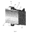
- FIG. 2 shows the guidance tool 104 in greater detail than in figure 1 .
- the sleeve 106 comprises a first half 106' and a second half 106". It can be seen that the two halves, 106' and 106", when put together, form a sleeve with a cylindrical inner surface. The cylindrical inner surface is shaped and sized to engage with the pipe end 102.
- the first half of the sleeve 106' includes a cut-out portion 113 where the sleeve material has been removed. The cut-out portion 113 is arranged to prevent the sleeve 106 from fouling features of the pipe end 100 or socket arrangement 102 such as bonding lugs during the installation process and removal of the sleeve 106.
- the clamp 108 comprises a first half 108' and a second half 108".
- the clamp 108 may be placed around the sleeve 106 and locked in position to removably engage the sleeve with the pipe end 100.
- the clamp is locked in position by use of the quick-release fasteners 116.
- the sleeve includes a flange portion 112 against which the clamp 108 is arranged to abut, and a male insert 114 located on the outer surface of the sleeve 106 arranged to engage with a female insert on the inner surface of the clamp 108 to ensure the correct location of the clamp 108.
- Figure 3 shows the guidance tool as shown in figures 1 and 2 , where the first half 106' and second half 106" of the sleeve 106 are in contact with each other, and the clamp 108 is locked in position around the sleeve 106.
- FIG. 4 shows a guidance tool 200 according to a second embodiment of the invention.
- the sleeve 206 is essentially the same as the sleeve 106.
- the clamp 208 comprises a first half 208' and a second half 208" that are joined via a hinge arrangement 210.
- Each half of the clamp 208', 208" includes a protrusion 212', 212", approximately opposite the hinge arrangement 210.
- the two protrusions 212', 212 may be held together manually to lock the clamp 208 in position on the sleeve 206.
- Such an arrangement may increase the ease of use of the guidance tool as no additional fastening mechanism is required.
- the two halves of the clamp, 208', 208" are connected together by the hinge arrangement 210, reducing the possibility of losing one half of the clamp.
- the two protrusions 212', 212" may be locked together using a clip or other suitable mechanical locking mechanism.
- Figure 5 shows a guidance tool 300 according to a third embodiment of the invention.
- the guidance tool comprises a first half 302 and a second half 304, each half comprising a single moulded piece combining both the function of a sleeve and clamping arrangement.
- the guidance tool is fastened to a pipe end in the same way as the guidance tool substantially as described with reference to figure 4 .
- the guidance tool 300 includes a fastener 308 arranged to lock the first half 302 and second half 304 together. Providing two, one-piece, halves that are hinged together reduces the possibility of losing parts of the guidance tool and may increase the ease of use of the tool during a pipe fitting operation.
- the first half 302 and second half 304 each include a U-grip 306, the U grips 306 configured such that when the clamp is fastened around a pipe end, the U-grips compress the sleeve arrangement onto the surface of the pipe end.
- FIG. 6 shows a clamp 400 according to a fourth aspect of the invention.
- the clamp 400 is approximately oval shaped and comprises a first half 402 and a second half 404, the two halves 402, 404, connected together by a hinge arrangement 406 and a fastening arrangement 408.
- Each half 402, 404 includes a female insert 410 to allow the clamp to be located on a suitable sleeve.
- Providing an oval clamp 400 as shown in figure 4 may allow the clamp to be used with a number of different sized sleeves, each sleeve being specifically sized for a certain pipe end diameter.
- the sleeves for use with the oval clamp may include a standard size male part for insertion into the female insert 410.
- the female insert 410 may be arranged to receive a number of different sized shims in order that the clamp 400 may be used on different sized sleeves.
- Providing an adjustable clamp as shown in figure 6 may increase the versatility of the clamp such that it may be used in a variety of guidance tool configurations, each configuration specific to a particular pipe end or socket diameter.
- FIGS 7A and 7B show a pipe installation method according to a fifth aspect of the invention.
- Figure 7A show a guidance tool 700 fastened to a pipe end 702 prior to the pipe end 702 being manually inserted into a socket arrangement 704.
- the socket arrangement 700 corresponds to that described in relation to the first embodiment of the invention but it will be appreciated any of the described guidance tools may be used.
- the pipe end 702 and guidance tool 700 are partially inserted into the socket arrangement 704, as shown in Figure 7B .
- the guidance tool is removed from the pipe end fitting 702, in this case by removing the fasteners from the clamp and sliding the sleeve away from the socket arrangement 704 and out of engagement with the pipe end 702.
- Figure 8 shows an aircraft 800 including a fuel pipe system including a fuel pipe coupling 802 that has been installed using a guidance tool according to any of the above described embodiments of the invention.
Landscapes
- Engineering & Computer Science (AREA)
- Mechanical Engineering (AREA)
- General Engineering & Computer Science (AREA)
- Clamps And Clips (AREA)
- Quick-Acting Or Multi-Walled Pipe Joints (AREA)
Abstract
Description
- The present invention concerns a tool for use in aircraft construction. More particularly, but not exclusively, this invention concerns a tool and method for installation of a pipe end within a socket, wherein the pipe end and the socket are part of an aircraft fuel system.
- In a typical aircraft fuel pipe system installation process, the fuel pipe connectors comprising pipe-end receiving socket arrangements are installed in the aircraft structure prior to the fuel pipes being installed. An aircraft engineer may then manually install the fuel pipes by pushing the fuel pipe ends into the fuel pipe connectors. During this push-fit installation, it is important that the angular misalignment between the axial centrelines of the pipe end and the socket is minimised in order to avoid damage to the pipe end or the socket arrangement. Damage to the pipe end or the socket arrangement may include damage to a seal between the pipe end and the socket arrangement. Damage to the pipe end or the socket arrangement during the installation process may lead to potentially costly and hazardous fuel leakages during use of the aircraft.
- Typically, the tolerance level required is no more than ±2 degrees angular misalignment between the axial centrelines of the pipe end and the socket arrangement. However, it may be difficult to measure and/or monitor the accuracy achieved during the push fit process. Additionally, it is desirable to maintain a gap between the end of the pipe end and the socket arrangement, that allows the pipe end to float in a longitudinal direction when installed in the socket arrangement. In the aircraft industry this is typically known as the coupling gap.
- The present invention seeks to mitigate the above-mentioned problems.
- The present invention provides, according to a first aspect, a guidance tool for restricting the potential angular misalignment between the axial centrelines of a pipe end and corresponding socket arrangement during a pipe installation process, the guidance tool comprising:
- a sleeve; and
- a clamp; wherein the clamp is configured to removably engage the sleeve with an external surface of a pipe end, such that at least part of the sleeve and pipe end may be inserted into a corresponding socket arrangement.
- The guidance tool, when engaged with a pipe end, restricts the potential angular misalignment between the axial centrelines of a pipe end and corresponding socket arrangement when the pipe end is pushed into the socket arrangement. The sleeve reduces the free space between the external surface of a pipe end and the internal surface of a corresponding socket arrangement, the free space which may allow angular misalignment of the pipe end and socket arrangement beyond the desired tolerance levels during the pipe installation process. The sleeve may remove substantially all of the free space between the external surface of a pipe end and the internal surface of a corresponding socket arrangement during installation of the pipe end into the socket arrangement.
- The clamp may be configured to allow removal of the sleeve from engagement with the external surface of a pipe end, once the pipe end has been inserted into a corresponding socket arrangement.
- The sleeve may be approximately cylindrical. The sleeve may comprise a first half and a second half, the first half and second half being distinct and separate elements. The first half and the second half of the sleeve may be connected to each other by a hinge.
- The clamp may be approximately cylindrical. The clamp may comprise a first half and second half, the first half and second half being distinct and separate elements. The clamp may comprise a locking mechanism to maintain the sleeve in removable engagement with a pipe end when the locking mechanism is in the locked position. The locking mechanism may allow removal of the sleeve from removable engagement with a pipe end when the locking mechanism is in the unlocked position. The locking mechanism may be one or more fasteners. The one or more fasteners may be quick release fasteners, for example spring loaded fasteners. The one or more fasteners may be a screw, Allen bolt, or any other suitable joining means. The clamp may comprise a first half and a second half, the first half and second half connected to each other by a hinge. The first half and second half of the clamp may respectively include a first protrusion and second protrusion, such that bringing the first protrusion and second protrusion into contact locks the clamp. A clip may maintain the first protrusion and second protrusion in contact with each other. Alternatively, an engineer may hold the first protrusion and second protrusion together during the installation process in order to lock the clamp into position. In such an arrangement, the clamp may be easily unlocked by releasing the first protrusion and second protrusion, thereby allowing easy removal of the installation device from a pipe end and socket arrangement when connecting the two. The external surface of the clamp may include features configured to allow an engineer to hold the clamp together. The external surface of the clamp may include gripping portions.
- The clamp may be arranged to limit the extent to which the sleeve may be inserted into the socket arrangement. The clamp may be arranged to abut the socket arrangement when the pipe end is in the desired installed position.
- The clamp and the sleeve may be separable and distinct elements. Alternatively the clamp and the sleeve may be integrated such that they are not separable. A first half of the sleeve may be integrated with a first half of the clamp and the second half of the sleeve may be integrated with the second half of the clamp. The integrated halves may be formed by a single moulding or machining process.
- The guidance tool may comprise a material chosen to be softer than the material from which the pipe end and socket arrangement the guidance tool is designed to be used with is made of. The guidance tool may comprise a plastics material. The plastics material may be nylon or any other suitable material. The softer material may reduce the possibility that the guidance tool damages a pipe end or socket arrangement during the installation process. The guidance tool may comprise a low-friction material. A low-friction material may facilitate the installation of the pipe end and guidance tool within the socket arrangement.
- The guidance tool may be arranged for use with single or double walled pipe ends and single or double walled socket arrangements. The clamp and/or the sleeve may include sections of material that have been removed in order to avoid damage to features of pipe ends or socket arrangements, for example bonding lugs.
- A second aspect of the invention provides a pipe end and a guidance tool removably engaged with the pipe end, the guidance tool as substantially described with respect to the first aspect of the invention.
- A third aspect of the invention provides a pipe end fitting and a guidance tool removably engaged with the pipe end, the invention further including a socket arrangement, whereby the pipe end and guidance tool at least partially extend into the socket arrangement.
- A fourth aspect of the invention provides a method of installing a pipe end into a socket arrangement in an aircraft structure, the method comprising the steps of:
- removably engaging a guidance tool according to a first aspect of the invention with the pipe end;
- inserting the pipe end and guidance tool at least partially into the socket arrangement; and
- removing the guidance tool from the pipe end.
- The guidance tool may be as described with respect to any of the first, second, or third aspects of the invention.
- Removably engaging a guidance tool with the pipe end may comprise the step of locking the guidance tool to the pipe end fitting. The step of locking the guidance tool to the pipe end fitting may comprise the use of quick release fasteners. The step of locking the guidance tool to the pipe end fitting may comprise an installation engineer physically biasing the guidance tool into contact with the pipe end during the installation process. Removing the guidance tool from the pipe end may comprise unlocking the guidance tool. The guidance tool may be removed from the pipe end by sliding it away from and out of the socket arrangement, then opening the guidance tool to allow it to be fully removed from the pipe end. The guidance tool may be opened by being split into two or more parts. The guidance tool may comprise a hinge allowing expansion of the tool without the tool being fully split into two or more parts. This may reduce the possibility of parts of the guidance tool being lost.
- A fifth aspect of the invention provides an aircraft, the aircraft comprising a pipe structure constructed according to the method described above or using a guidance tool as described above with regards to any aspect of the invention.
- It will of course be appreciated that features described in relation to one aspect of the present invention may be incorporated into other aspects of the present invention. For example, the method of the invention may incorporate any of the features described with reference to the apparatus of the invention and vice versa.
- Embodiments of the present invention will now be described by way of example only with reference to the accompanying schematic drawings of which:
- Figure 1
- shows a cross-section view of a guidance tool and fuel pipe coupling according to a first embodiment of the invention;
- Figure 2
- shows an exploded view of the guidance tool according to the first embodiment of the invention;
- Figure 3
- shows an isometric view of the guidance tool according to the first embodiment of the invention;
- Figure 4
- shows an isometric view of a guidance tool according to a second embodiment of the invention;
- Figure 5
- shows an isometric view of a guidance tool according to a third embodiment of the invention;
- Figure 6
- shows an isometric view of a clamp for use with a guidance tool according to a fourth embodiment of the invention;
- Figures 7A and 7B
- show a pipe connection method according to a fifth embodiment of the invention; and
- Figure 8
- shows an aircraft comprising a fuel system including a fuel pipe connection according to a sixth embodiment of the invention.
-
Figure 1 shows a fuel pipe coupling in an aircraft, the fuel pipe coupling comprising apipe end 100, asocket arrangement 102, and aguidance tool 104. Thepipe end 100 is partially inserted within thesocket arrangement 102. Theguidance tool 104 comprises asleeve 106 and aclamp 108. Thesleeve 106 is held in removable engagement with the outer surface of thepipe 100 by theclamp 108. As can be seen infigure 1 , thesleeve 106 is at least partially inserted into thesocket 102 such that it removes part of the free space between the outer surface of thepipe 100 and the inner surface of thesocket arrangement 102. This free space is to allow slight angular movement of the pipe coupling when the aircraft is in the air. Such angular movement may be caused by vibration of the aircraft during flight. However, during the pipe installation process, when thepipe end 100 is inserted into thesocket arrangement 102, the free space may allow angular misalignment of the axial centrelines of thefuel pipe 100 andsocket arrangement 102 to an extent where the fuel pipe coupling is damaged. The damage may be to theseal 110 located between the far end of thepipe end 100 and thesocket arrangement 102, or other elements of the fuel pipe coupling. - The arrangement as described for
figure 1 allows thepipe end 100 to be inserted into thesocket arrangement 102 with the potential for angular misalignment between the axial centrelines of thepipe end 100 and thesocket arrangement 102 restricted to no more than ±2 degrees, due to the removal of the free space by thesleeve 106 as described above. Theclamp 108 abuts thesocket arrangement 102 limiting the distance thesleeve 106 may be inserted into thesocket arrangement 102. Theclamp 108 may also be used to control the gap between the end of thepipe end 100 and thesocket arrangement 102, such that thepipe end 100 andsocket arrangement 102 are joined with a coupling gap. -
Figure 2 shows theguidance tool 104 in greater detail than infigure 1 . Thesleeve 106 comprises a first half 106' and asecond half 106". It can be seen that the two halves, 106' and 106", when put together, form a sleeve with a cylindrical inner surface. The cylindrical inner surface is shaped and sized to engage with thepipe end 102. The first half of the sleeve 106' includes a cut-outportion 113 where the sleeve material has been removed. The cut-outportion 113 is arranged to prevent thesleeve 106 from fouling features of thepipe end 100 orsocket arrangement 102 such as bonding lugs during the installation process and removal of thesleeve 106. Theclamp 108 comprises a first half 108' and asecond half 108". Theclamp 108 may be placed around thesleeve 106 and locked in position to removably engage the sleeve with thepipe end 100. In this embodiment the clamp is locked in position by use of the quick-release fasteners 116. The sleeve includes aflange portion 112 against which theclamp 108 is arranged to abut, and amale insert 114 located on the outer surface of thesleeve 106 arranged to engage with a female insert on the inner surface of theclamp 108 to ensure the correct location of theclamp 108. -
Figure 3 shows the guidance tool as shown infigures 1 and2 , where the first half 106' andsecond half 106" of thesleeve 106 are in contact with each other, and theclamp 108 is locked in position around thesleeve 106. -
Figure 4 shows aguidance tool 200 according to a second embodiment of the invention. The sleeve 206 is essentially the same as thesleeve 106. Theclamp 208 comprises a first half 208' and asecond half 208" that are joined via ahinge arrangement 210. Each half of theclamp 208', 208" includes aprotrusion 212', 212", approximately opposite thehinge arrangement 210. The twoprotrusions 212', 212", may be held together manually to lock theclamp 208 in position on the sleeve 206. Such an arrangement may increase the ease of use of the guidance tool as no additional fastening mechanism is required. Additionally, the two halves of the clamp, 208', 208", are connected together by thehinge arrangement 210, reducing the possibility of losing one half of the clamp. In alternative embodiments, the twoprotrusions 212', 212", may be locked together using a clip or other suitable mechanical locking mechanism. -
Figure 5 shows aguidance tool 300 according to a third embodiment of the invention. In this embodiment the guidance tool comprises afirst half 302 and asecond half 304, each half comprising a single moulded piece combining both the function of a sleeve and clamping arrangement. Functionally, the guidance tool is fastened to a pipe end in the same way as the guidance tool substantially as described with reference tofigure 4 . Theguidance tool 300 includes afastener 308 arranged to lock thefirst half 302 andsecond half 304 together. Providing two, one-piece, halves that are hinged together reduces the possibility of losing parts of the guidance tool and may increase the ease of use of the tool during a pipe fitting operation. Thefirst half 302 andsecond half 304 each include a U-grip 306, the U grips 306 configured such that when the clamp is fastened around a pipe end, the U-grips compress the sleeve arrangement onto the surface of the pipe end. -
Figure 6 shows aclamp 400 according to a fourth aspect of the invention. Theclamp 400 is approximately oval shaped and comprises afirst half 402 and asecond half 404, the twohalves hinge arrangement 406 and afastening arrangement 408. Eachhalf female insert 410 to allow the clamp to be located on a suitable sleeve. Providing anoval clamp 400 as shown infigure 4 , may allow the clamp to be used with a number of different sized sleeves, each sleeve being specifically sized for a certain pipe end diameter. The sleeves for use with the oval clamp may include a standard size male part for insertion into thefemale insert 410. Thefemale insert 410 may be arranged to receive a number of different sized shims in order that theclamp 400 may be used on different sized sleeves. Providing an adjustable clamp as shown infigure 6 may increase the versatility of the clamp such that it may be used in a variety of guidance tool configurations, each configuration specific to a particular pipe end or socket diameter. -
Figures 7A and7B show a pipe installation method according to a fifth aspect of the invention.Figure 7A show aguidance tool 700 fastened to apipe end 702 prior to thepipe end 702 being manually inserted into asocket arrangement 704. In this case thesocket arrangement 700 corresponds to that described in relation to the first embodiment of the invention but it will be appreciated any of the described guidance tools may be used. Once theguidance tool 700 has been fastened to thepipe end 702, thepipe end 702 andguidance tool 700 are partially inserted into thesocket arrangement 704, as shown inFigure 7B . Once thepipe end 702 is properly located in thesocket arrangement 704, the guidance tool is removed from the pipe end fitting 702, in this case by removing the fasteners from the clamp and sliding the sleeve away from thesocket arrangement 704 and out of engagement with thepipe end 702. -
Figure 8 shows anaircraft 800 including a fuel pipe system including afuel pipe coupling 802 that has been installed using a guidance tool according to any of the above described embodiments of the invention. - Whilst the present invention has been described and illustrated with reference to particular embodiments, it will be appreciated by those of ordinary skill in the art that the invention lends itself to many different variations not specifically illustrated herein.
- Where in the foregoing description, integers or elements are mentioned which have known, obvious or foreseeable equivalents, then such equivalents are herein incorporated as if individually set forth. Reference should be made to the claims for determining the true scope of the present invention, which should be construed so as to encompass any such equivalents. It will also be appreciated by the reader that integers or features of the invention that are described as preferable, advantageous, convenient or the like are optional and do not limit the scope of the independent claims. Moreover, it is to be understood that such optional integers or features, whilst of possible benefit in some embodiments of the invention, may not be desirable, and may therefore be absent, in other embodiments.
Claims (20)
- A guidance tool for restricting the potential angular misalignment between the axial centrelines of a pipe end and corresponding socket arrangement during a pipe installation process, the guidance tool comprising:a sleeve; anda clamp; wherein the clamp is configured to removably engage the sleeve with an external surface of a pipe end, such that at least part of the sleeve and pipe end may be inserted into a corresponding socket arrangement.
- A guidance tool as claimed in claim 1, wherein the clamp is configured to allow removal of the sleeve from engagement with the external surface of a pipe end, once the pipe end has been inserted into a corresponding socket arrangement.
- A guidance tool as claimed in claim 1 or claim 2, wherein the sleeve is approximately cylindrical.
- A guidance tool as claimed in any preceding claim, wherein the sleeve comprises a first half and a second half, the first half and second half being distinct and separate elements.
- A guidance tool as claimed in any preceding claim, wherein the sleeve comprises a first half and a second half, the first half and the second half of the sleeve connected to each other by a hinge.
- A guidance tool as claimed in any preceding claim, wherein the clamp is approximately cylindrical.
- A guidance tool as claimed in any preceding claim, wherein the clamp comprises a first half and second half, the first half and second half being distinct and separate elements.
- A guidance tool as claimed in any preceding claim, wherein the clamp comprises a locking mechanism arranged to maintain the sleeve in removable engagement with a pipe end when the locking mechanism is in the locked position.
- A guidance tool as claimed in claim 8, wherein the locking mechanism is arranged to allow removal of the sleeve from removable engagement with a pipe end when the locking mechanism is in the unlocked position.
- A guidance tool as claimed in claim 8 or claim 9, wherein the locking mechanism is one or more fasteners
- A guidance tool as claimed in any preceding claim, wherein the clamp comprises a first half and a second half, the first half and second half connected to each other by a hinge.
- A guidance tool as claimed in claim 11, wherein the first half and second half of the clamp respectively include a first protrusion and second protrusion, such that bringing the first protrusion and second protrusion into contact locks the clamp.
- A guidance tool as claimed in any preceding claim, wherein the clamp comprises an outer surface including a gripping arrangement.
- A guidance tool as claimed in any preceding claim, configured to limit the distance a pipe end may be inserted into a socket arrangement during a pipe installation process.
- A pipe end and a guidance tool removably engaged with the pipe end, the guidance tool according to any of claims 1 to 14.
- A pipe end fitting and a guidance tool removably engaged with the pipe end, and a socket arrangement, whereby the pipe end and guidance tool at least partially extend into the socket arrangement, the guidance tool according to any of claims 1 to 14.
- A method of installing a pipe end into a socket arrangement in an aircraft structure, the method comprising the steps of:removably engaging a guidance tool according to claim 1 with the pipe end;inserting the pipe end and guidance tool at least partially into the socket arrangement; andremoving the guidance tool from the pipe end.
- A method as claimed in claim 17 wherein the step of removably engaging the guidance tool with the pipe end comprises the step of locking the guidance tool to the pipe end fitting.
- A method as claimed in claim 18, wherein the step of removing the guidance tool from the pipe end comprises unlocking the guidance tool.
- A method as claimed in any of claims 17 to 19, wherein the guidance tool is removed from the pipe end by sliding it away from and out of the socket arrangement.
Applications Claiming Priority (1)
| Application Number | Priority Date | Filing Date | Title |
|---|---|---|---|
| GBGB1120239.7A GB201120239D0 (en) | 2011-11-23 | 2011-11-23 | Aircraft tool |
Publications (2)
| Publication Number | Publication Date |
|---|---|
| EP2596913A2 true EP2596913A2 (en) | 2013-05-29 |
| EP2596913A3 EP2596913A3 (en) | 2017-04-05 |
Family
ID=45475619
Family Applications (1)
| Application Number | Title | Priority Date | Filing Date |
|---|---|---|---|
| EP12192483.1A Withdrawn EP2596913A3 (en) | 2011-11-23 | 2012-11-13 | Aircraft tool |
Country Status (4)
| Country | Link |
|---|---|
| US (1) | US9347597B2 (en) |
| EP (1) | EP2596913A3 (en) |
| CN (1) | CN103129748B (en) |
| GB (1) | GB201120239D0 (en) |
Cited By (2)
| Publication number | Priority date | Publication date | Assignee | Title |
|---|---|---|---|---|
| FR3075083A1 (en) * | 2017-12-19 | 2019-06-21 | Airbus Operations (S.A.S.) | TOOL AND METHOD FOR INSTALLATION OF SEAL SEAL BY ALLOWING PRE-COMPRESSION TO ASSEMBLE TWO TUBULAR PIECES |
| CN111906168A (en) * | 2020-07-29 | 2020-11-10 | 西安飞机工业(集团)有限责任公司 | Pipeline installation axial shape correction method and shape correction tool |
Families Citing this family (3)
| Publication number | Priority date | Publication date | Assignee | Title |
|---|---|---|---|---|
| GB201120239D0 (en) * | 2011-11-23 | 2012-01-04 | Airbus Operations Ltd | Aircraft tool |
| US9816849B2 (en) * | 2015-05-22 | 2017-11-14 | Nordson Corporation | Dispensing apparatus and methods utilizing quick connect member to secure fluid body and actuator body |
| CN108357694B (en) * | 2018-04-24 | 2024-02-20 | 中电科芜湖钻石飞机制造有限公司 | General aircraft ventilation pipe joint installation frock |
Citations (2)
| Publication number | Priority date | Publication date | Assignee | Title |
|---|---|---|---|---|
| US5226678A (en) * | 1987-03-31 | 1993-07-13 | Petranto Joseph J | Split gland |
| US20100326671A1 (en) * | 2009-04-07 | 2010-12-30 | Frank's International, Inc. | Interference-fit stop collar and method of positioning a device on a tubular |
Family Cites Families (13)
| Publication number | Priority date | Publication date | Assignee | Title |
|---|---|---|---|---|
| CH509540A (en) | 1969-05-10 | 1971-06-30 | Epitestudomanyi Intezet | Device for assembling pipelines |
| US4335632A (en) | 1979-01-05 | 1982-06-22 | Augerscope, Inc. | Internal pipe wrench |
| GB2212780A (en) | 1987-11-24 | 1989-08-02 | James Heber Libby | Pipe handling/lifting tool |
| US6182347B1 (en) * | 1999-12-06 | 2001-02-06 | Patent Consultants & Services, Inc. | Disconnect tool for a spring-lock® connector |
| JP3567125B2 (en) * | 2000-10-16 | 2004-09-22 | 日本ピラー工業株式会社 | Inner ring press fitting jig for resin pipe |
| BRPI0413983A (en) * | 2003-08-28 | 2006-11-07 | Timberline Tool & Casting Inc | tool |
| US7325287B2 (en) * | 2004-11-12 | 2008-02-05 | Cinram International Inc. | Apparatus for minimizing registration errors when mounting plate cylinders in an optical disc printing system |
| BRPI0917019A2 (en) * | 2008-08-15 | 2016-02-16 | Frank S Inr Inc | cementing device and method |
| JP2010106966A (en) * | 2008-10-30 | 2010-05-13 | Toyota Motor Corp | Hose clamp |
| DE102010063988A1 (en) * | 2010-12-22 | 2012-06-28 | Airbus Operations Gmbh | Tool for mounting and removing a sleeve on flanges or flanges, positioning, tool assembly and method |
| CN202030004U (en) * | 2011-02-15 | 2011-11-09 | 中国航空工业集团公司西安飞机设计研究所 | Oil drainage tool |
| US9004545B2 (en) * | 2011-03-07 | 2015-04-14 | Nordson Corporation | Clamp for sanitary fitting |
| GB201120239D0 (en) * | 2011-11-23 | 2012-01-04 | Airbus Operations Ltd | Aircraft tool |
-
2011
- 2011-11-23 GB GBGB1120239.7A patent/GB201120239D0/en not_active Ceased
-
2012
- 2012-11-13 EP EP12192483.1A patent/EP2596913A3/en not_active Withdrawn
- 2012-11-23 US US13/684,351 patent/US9347597B2/en not_active Expired - Fee Related
- 2012-11-23 CN CN201210480572.5A patent/CN103129748B/en not_active Expired - Fee Related
Patent Citations (2)
| Publication number | Priority date | Publication date | Assignee | Title |
|---|---|---|---|---|
| US5226678A (en) * | 1987-03-31 | 1993-07-13 | Petranto Joseph J | Split gland |
| US20100326671A1 (en) * | 2009-04-07 | 2010-12-30 | Frank's International, Inc. | Interference-fit stop collar and method of positioning a device on a tubular |
Cited By (5)
| Publication number | Priority date | Publication date | Assignee | Title |
|---|---|---|---|---|
| FR3075083A1 (en) * | 2017-12-19 | 2019-06-21 | Airbus Operations (S.A.S.) | TOOL AND METHOD FOR INSTALLATION OF SEAL SEAL BY ALLOWING PRE-COMPRESSION TO ASSEMBLE TWO TUBULAR PIECES |
| EP3501737A1 (en) * | 2017-12-19 | 2019-06-26 | Airbus Operations S.A.S. | Tool and method for installing a seal allowing pre-compression for assembling two tubular parts |
| US11045931B2 (en) | 2017-12-19 | 2021-06-29 | Airbus Operations Ltd. | Tool and method for installing a seal by allowing a precompression to join two tubular parts |
| CN111906168A (en) * | 2020-07-29 | 2020-11-10 | 西安飞机工业(集团)有限责任公司 | Pipeline installation axial shape correction method and shape correction tool |
| CN111906168B (en) * | 2020-07-29 | 2022-03-15 | 西安飞机工业(集团)有限责任公司 | Pipeline installation axial shape correction method and shape correction tool |
Also Published As
| Publication number | Publication date |
|---|---|
| US9347597B2 (en) | 2016-05-24 |
| GB201120239D0 (en) | 2012-01-04 |
| EP2596913A3 (en) | 2017-04-05 |
| CN103129748A (en) | 2013-06-05 |
| US20130127152A1 (en) | 2013-05-23 |
| CN103129748B (en) | 2016-08-03 |
Similar Documents
| Publication | Publication Date | Title |
|---|---|---|
| EP2596913A2 (en) | Aircraft tool | |
| US7435050B2 (en) | Split flange V-groove and anti-rotation mating system | |
| US20090278347A1 (en) | Quick connector, release tool, and method therefor | |
| US10291009B2 (en) | Integrated piping conduit with adaptor device and method | |
| US6964435B2 (en) | Coupling for connecting hydraulic ducts | |
| US10221879B2 (en) | Panel mount fastener having an outer sleeve with a collapsible end portion | |
| US9822912B2 (en) | Push-to-connect fitting device, arrangement and method | |
| US20150125235A1 (en) | Attachment device and method for attaching elements | |
| CN110770488B (en) | System and apparatus for catheter compression retainer | |
| US20160069504A1 (en) | Locking device | |
| US20180090919A1 (en) | Integrated Piping Conduit with Adaptor Device and Method | |
| US20110140414A1 (en) | PTC Fitting Cartridge | |
| US8602674B2 (en) | Device for connecting two components | |
| US6978754B2 (en) | Manifold sensor retention system | |
| US20200340602A1 (en) | Pipe clamp | |
| US11811200B2 (en) | Installation tool and method | |
| EP3403306B1 (en) | Integrated piping conduit with adaptor device and method | |
| EP4047252A1 (en) | Quick connector with bracket retainer | |
| US20150101176A1 (en) | Method and Apparatus for Fitting a Sleeve | |
| US20180202588A1 (en) | Combination Flange In a Tube Connector | |
| US6126205A (en) | Connection tool for low profile connections | |
| US20240183476A1 (en) | Fluid Coupling Device and Method for Coupling Two Fluid Lines | |
| US20030034647A1 (en) | Removable pipe coupler | |
| CN114207341B (en) | Compact and detachable fluid connection device | |
| US11655922B2 (en) | Method for assembling a tube and a fitting body |
Legal Events
| Date | Code | Title | Description |
|---|---|---|---|
| PUAI | Public reference made under article 153(3) epc to a published international application that has entered the european phase |
Free format text: ORIGINAL CODE: 0009012 |
|
| AK | Designated contracting states |
Kind code of ref document: A2 Designated state(s): AL AT BE BG CH CY CZ DE DK EE ES FI FR GB GR HR HU IE IS IT LI LT LU LV MC MK MT NL NO PL PT RO RS SE SI SK SM TR |
|
| AX | Request for extension of the european patent |
Extension state: BA ME |
|
| PUAL | Search report despatched |
Free format text: ORIGINAL CODE: 0009013 |
|
| AK | Designated contracting states |
Kind code of ref document: A3 Designated state(s): AL AT BE BG CH CY CZ DE DK EE ES FI FR GB GR HR HU IE IS IT LI LT LU LV MC MK MT NL NO PL PT RO RS SE SI SK SM TR |
|
| AX | Request for extension of the european patent |
Extension state: BA ME |
|
| RIC1 | Information provided on ipc code assigned before grant |
Ipc: B25B 27/00 20060101AFI20170224BHEP Ipc: F16L 1/10 20060101ALI20170224BHEP Ipc: B25B 27/10 20060101ALI20170224BHEP |
|
| STAA | Information on the status of an ep patent application or granted ep patent |
Free format text: STATUS: THE APPLICATION HAS BEEN PUBLISHED |
|
| STAA | Information on the status of an ep patent application or granted ep patent |
Free format text: STATUS: THE APPLICATION IS DEEMED TO BE WITHDRAWN |
|
| 18D | Application deemed to be withdrawn |
Effective date: 20171006 |