EP2596871A2 - Passive temperature control of HPC rotor coating - Google Patents
Passive temperature control of HPC rotor coating Download PDFInfo
- Publication number
- EP2596871A2 EP2596871A2 EP12193074.7A EP12193074A EP2596871A2 EP 2596871 A2 EP2596871 A2 EP 2596871A2 EP 12193074 A EP12193074 A EP 12193074A EP 2596871 A2 EP2596871 A2 EP 2596871A2
- Authority
- EP
- European Patent Office
- Prior art keywords
- fixture
- spray
- base
- temperature
- coating
- Prior art date
- Legal status (The legal status is an assumption and is not a legal conclusion. Google has not performed a legal analysis and makes no representation as to the accuracy of the status listed.)
- Withdrawn
Links
Images



Classifications
-
- B—PERFORMING OPERATIONS; TRANSPORTING
- B05—SPRAYING OR ATOMISING IN GENERAL; APPLYING FLUENT MATERIALS TO SURFACES, IN GENERAL
- B05B—SPRAYING APPARATUS; ATOMISING APPARATUS; NOZZLES
- B05B13/00—Machines or plants for applying liquids or other fluent materials to surfaces of objects or other work by spraying, not covered by groups B05B1/00 - B05B11/00
- B05B13/02—Means for supporting work; Arrangement or mounting of spray heads; Adaptation or arrangement of means for feeding work
- B05B13/0285—Stands for supporting individual articles to be sprayed, e.g. doors, vehicle body parts
-
- B—PERFORMING OPERATIONS; TRANSPORTING
- B05—SPRAYING OR ATOMISING IN GENERAL; APPLYING FLUENT MATERIALS TO SURFACES, IN GENERAL
- B05B—SPRAYING APPARATUS; ATOMISING APPARATUS; NOZZLES
- B05B12/00—Arrangements for controlling delivery; Arrangements for controlling the spray area
- B05B12/16—Arrangements for controlling delivery; Arrangements for controlling the spray area for controlling the spray area
- B05B12/20—Masking elements, i.e. elements defining uncoated areas on an object to be coated
-
- B—PERFORMING OPERATIONS; TRANSPORTING
- B05—SPRAYING OR ATOMISING IN GENERAL; APPLYING FLUENT MATERIALS TO SURFACES, IN GENERAL
- B05D—PROCESSES FOR APPLYING FLUENT MATERIALS TO SURFACES, IN GENERAL
- B05D1/00—Processes for applying liquids or other fluent materials
- B05D1/02—Processes for applying liquids or other fluent materials performed by spraying
-
- B—PERFORMING OPERATIONS; TRANSPORTING
- B05—SPRAYING OR ATOMISING IN GENERAL; APPLYING FLUENT MATERIALS TO SURFACES, IN GENERAL
- B05D—PROCESSES FOR APPLYING FLUENT MATERIALS TO SURFACES, IN GENERAL
- B05D3/00—Pretreatment of surfaces to which liquids or other fluent materials are to be applied; After-treatment of applied coatings, e.g. intermediate treating of an applied coating preparatory to subsequent applications of liquids or other fluent materials
- B05D3/02—Pretreatment of surfaces to which liquids or other fluent materials are to be applied; After-treatment of applied coatings, e.g. intermediate treating of an applied coating preparatory to subsequent applications of liquids or other fluent materials by baking
- B05D3/0218—Pretreatment, e.g. heating the substrate
-
- B—PERFORMING OPERATIONS; TRANSPORTING
- B05—SPRAYING OR ATOMISING IN GENERAL; APPLYING FLUENT MATERIALS TO SURFACES, IN GENERAL
- B05B—SPRAYING APPARATUS; ATOMISING APPARATUS; NOZZLES
- B05B7/00—Spraying apparatus for discharge of liquids or other fluent materials from two or more sources, e.g. of liquid and air, of powder and gas
- B05B7/16—Spraying apparatus for discharge of liquids or other fluent materials from two or more sources, e.g. of liquid and air, of powder and gas incorporating means for heating or cooling the material to be sprayed
- B05B7/20—Spraying apparatus for discharge of liquids or other fluent materials from two or more sources, e.g. of liquid and air, of powder and gas incorporating means for heating or cooling the material to be sprayed by flame or combustion
-
- F—MECHANICAL ENGINEERING; LIGHTING; HEATING; WEAPONS; BLASTING
- F01—MACHINES OR ENGINES IN GENERAL; ENGINE PLANTS IN GENERAL; STEAM ENGINES
- F01D—NON-POSITIVE DISPLACEMENT MACHINES OR ENGINES, e.g. STEAM TURBINES
- F01D5/00—Blades; Blade-carrying members; Heating, heat-insulating, cooling or antivibration means on the blades or the members
- F01D5/34—Rotor-blade aggregates of unitary construction, e.g. formed of sheet laminae
Definitions
- High pressure compressor (HPC) rotors are processed by coating with aluminum oxide in a spray process in which the particles are heated to approximately their melting point and the parts are heated to about 800 °F (427 °C). With the particles heated to their melting point or just superheated, the substrate temperature control is critical to achieving the desired level of bonding between particles in the coating.
- the coating will be too dense, hardness and modulus too high, and it will not machine correctly or have the required strain tolerance for service. If the part is too cool, bonding will be poor, resulting in a low durability, soft coating.
- a prior art method for controlling temperature of the part is to operate a secondary heat source that is controlled either in an open loop mode or in a closed loop mode based upon thermocouple or pyrometer feedback. This method therefore needs constant monitoring and potentially constant adjusting of the secondary heat source.
- the present invention is an improved method and a fixture design that facilitates use of the method.
- Heat from a spray torch is used to preheat the part after the part is mounted in a masking fixture.
- the masking fixture has a low thermal mass for rapid heating and a predetermined amount of integral insulation.
- the insulation serves to achieve a balance of heat loss to the environment compared to heat input from the spray process at the desired operating temperature. The temperature of the part remains constant.
- the spray torch with no powder feeding, is held closer to the rotating part than it is during coating. This maximizes the heating rate.
- the surface of the part exceeds the target temperature for coating.
- the torch is moved away to the correct distance for the coating process.
- powder is not fed to the torch and the part surface temperature drops to approach the target process temperature.
- the heat input rate control remains constant so the temperature of the part remains constant. As a result, coating quality is optimized.
- FIG. 1 a flow diagram of the method of this invention.
- FIG. 2 is a perspective view of the device used in the method of this invention, shown without the conventional spray torch that serves as a source of heat.
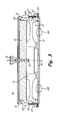
- FIG. 3 is a section view of the device of FIG. 2 .
- FIG. 4 is an enlarged view of the bottom right portion of the device of FIG. 3 .
- FIG. 5 is a graph showing the normalized part temperature as a function of time.
- FIG. 1 illustrates the method used to spray coat gas turbine parts such as rotors.
- Step 1 comprises placing the part to be spray coated in a device.
- the device described below, has insulation, space for convection heat flow, and access to the part for the spray to contact and coat the part.
- a test strip can also be mounted on the fixture for quality control.
- Step 2 comprises heating the part and fixture.
- the spray torch that will be used to coat the part can be used to provide the necessary heat, although other sources of heat can be used. What is needed is to heat the part and fixture so that even the interior of the part and the components of the fixture are at a predetermined temperature that has been determined experimentally to be that temperature at which the conductive, radiative, and convection heat flows cause the part and fixture to reach a steady state temperature during the next step.
- a typical steady state temperature is 800 °F (427 °C).
- Step 3 comprises spray coating the part, such as with aluminum oxide as desired.
- the spray torch may be positioned slightly further from the location used to heat the part and fixture, if necessary.
- the spray torch melts or greatly softens the coating particles and deposits them on the part. It is important to achieve the desired level of bonding between the particles in the coating on the part. If the part is too hot, the coating will be too dense, too hard, and have too high a modulus, so that it will not machine correctly. It will also not have the required strain tolerance for service. If the part is too cool, bonding will be poor, resulting in a low durability soft coating. Additionally, the part temperature during spray influences the residual stress contribution from thermal expansion coefficient mismatch between the coating and substrate.
- spray coating of parts One factor in spray coating of parts is that the spray broadens or fans after leaving the spray torch nozzle. If the spray direction is parallel to the line of sight to the part along a masking surface, half or more will end up going up and away from the masking surface and result in decreased coating thickness on the part adjacent to the masking. To remedy this, the spray is angled toward the masking to approach the part at an angle, thus coating the entire region to be sprayed.
- Step 4 simply comprises removing the part after it cools and the coating has bonded properly.
- the coating on the part is machined, Step 5, in some cases using a single point turning on a lathe with a diamond cutting tool.
- the part is now ready for use with good results.
- FIG. 2 shows the fixture device 10 of this invention in perspective.
- Fixture 10 is intended to be used in processes such as described above.
- the spray coating process is conventional but the temperature control is new, as described above. What is new is that fixture 10 is designed to retain the correct amount of heat during the coating process so that the part remains at a constant temperature to ensure optimization of the coating on the part.
- Fixture 10 is made from any solid material such as metal. In one embodiment fixture 10 is made from a 17-4 PH stainless steel alloy.
- Fixture 10 may be annular in shape, as shown in FIGS. 2 and 3 , and has an axis of rotation A in FIG. 3 .
- Upper insulating board 21 is fastened by bolt 13 to lifter knob 15 for ease of handling.
- Part 11 is located in an area 17 between fixture base 19 and insulation cover 21.
- Insulating cover 21 is made from any high temperature insulation material such as those used in furnaces and kilns.
- Fixture base 19 is made of a thermally stable metal, in one case 17-4 PH stainless steel.
- the metallic construction provides durable, close tolerance support for part 11 and lower mask 27 while providing features that help to thermally isolate the part.
- Fixture base plate 19 is thinned in region 102 to limit heat capacity and conduction from the perimeter of part 11 where the coating process provides heat input over area 104. Coating is applied to area 103 on part 11, the test sample 29 plus approximately 0.5 inches (1.27 cm) to either side to allow for passage of the entire spray plume 30 and uniform coating coverage.
- Upper insulation board 21 is protected from the spray process by top mask 31 with space 25 between board 21 and mask 31, best seen in FIG. 4 , to permit air or other gasses to circulate, thus creating a convection path sized to control the amount of heat loss by mask 31.
- Space 17 also provides a place for air or other gases to function to define heat convection paths, depending on the shape of part 11. If required, space 17 may be filled with insulating material or may be filled with conductive material as required to reduce or increase the rate of heat loss from the coated area as required to establish desired equilibrium temperature during the spray process. Mask 31 also prevents the part from becoming coated in areas where coating is not required.
- FIGS. 3 and 4 also show annular lower mask 27, holder 33 that holds test panel 29 in place and annular upper mask 31.
- Fixture base 19 locates part 11, mask 27 and test piece holder 33.
- upper mask 31 and upper insulating board 21 are located from part 11.
- Test panel holder 33 is fastened to the side 35 of fixture 10 with bolts 37.
- Test panel 29 is used for quality control of the coating but is not a component of part 11.
- FIG. 5 illustrates the achievement of a steady state part temperature using the method and device of this invention.
- FIG. 5 shows the part temperature, normalized to a scale of 0 to 1 rather in actual degrees, as a function of time.
- the first section of FIG. 4 up to about 1800 seconds uses a higher heat input parameter to help get the part up to temperature rapidly and also to soak heat into the center of the part. Parameters are then changed to those for coating, over a short duration such as about 100 seconds so the part temperature in the coating area (on the circumference of part 11) drops back down to within a chosen tolerance around the target. This drop in temperature is due to conduction to the part core as well as the more rapid heat loss to the environment that occurs at the higher temperature achieved during preheat.
- a second method of heat loss to the environment is by convective loss to the air. This rate is directly proportional to the difference in temperature between the part and air.
- Q is the thermal energy in joules
- h is the heat transfer coefficient (assumed independent of T here)
- A is the surface area of the heat being transferred
- T is the temperature of the object's surface and interior
- T env the temperature of the environment (the temperature far from the surface)
- ⁇ T(t) T(t) - T env .
- the third method of heat loss is by conduction to cooler regions of the part and fixturing. This is minimized by allowing the part to "soak" or allow time for heat to be conducted into the part center or hub, and by minimizing contact with the supports that hold this part and fixture to the turntable in the spray booth.
- spray deposition of a part is conducted at a temperature within the chosen tolerance and no adjustment of the operating conditions of the spraying process is needed or attempted after the required time has lapsed. In FIG. 5 , this occurs at about 2,250 seconds.
- the size of the insulation, the radiation, the paths of convection and conduction are balanced so that during the spray process, the heat input from the spray to the part is equal to the heat lost by convection, radiation and conduction. The balance may be determined experimentally. By eliminating feedback requirements and any need to change the heating or cooling of the part, substantial savings and efficiencies are achieved by the present invention. Proper coatings, as achieved by the present invention, provide coatings that have longer life as well.
Landscapes
- Turbine Rotor Nozzle Sealing (AREA)
- Coating Apparatus (AREA)
Abstract
Description
- High pressure compressor (HPC) rotors are processed by coating with aluminum oxide in a spray process in which the particles are heated to approximately their melting point and the parts are heated to about 800 °F (427 °C). With the particles heated to their melting point or just superheated, the substrate temperature control is critical to achieving the desired level of bonding between particles in the coating.
- If the part is too hot, the coating will be too dense, hardness and modulus too high, and it will not machine correctly or have the required strain tolerance for service. If the part is too cool, bonding will be poor, resulting in a low durability, soft coating.
- A prior art method for controlling temperature of the part is to operate a secondary heat source that is controlled either in an open loop mode or in a closed loop mode based upon thermocouple or pyrometer feedback. This method therefore needs constant monitoring and potentially constant adjusting of the secondary heat source.
- It would be an advantage to provide a method and a fixture design that would reduce or eliminate the need for temperature feedback. Elimination of a secondary heat source would also simplify the method.
- The present invention is an improved method and a fixture design that facilitates use of the method. Heat from a spray torch is used to preheat the part after the part is mounted in a masking fixture. The masking fixture has a low thermal mass for rapid heating and a predetermined amount of integral insulation. The insulation serves to achieve a balance of heat loss to the environment compared to heat input from the spray process at the desired operating temperature. The temperature of the part remains constant.
- During the preheat time, the spray torch, with no powder feeding, is held closer to the rotating part than it is during coating. This maximizes the heating rate. At a particular point in time, the surface of the part exceeds the target temperature for coating. After a predetermined time, the torch is moved away to the correct distance for the coating process. For some additional time, powder is not fed to the torch and the part surface temperature drops to approach the target process temperature. Once within a tolerance of the target temperature, powder is fed to the torch and the coating process is started with no further change in the heat input rate or part temperature. Thus the heat input rate control remains constant so the temperature of the part remains constant. As a result, coating quality is optimized.
-
FIG. 1 a flow diagram of the method of this invention. -
FIG. 2 is a perspective view of the device used in the method of this invention, shown without the conventional spray torch that serves as a source of heat. -
FIG. 3 is a section view of the device ofFIG. 2 . -
FIG. 4 is an enlarged view of the bottom right portion of the device ofFIG. 3 . -
FIG. 5 is a graph showing the normalized part temperature as a function of time. -
FIG. 1 illustrates the method used to spray coat gas turbine parts such as rotors.Step 1 comprises placing the part to be spray coated in a device. The device, described below, has insulation, space for convection heat flow, and access to the part for the spray to contact and coat the part. A test strip can also be mounted on the fixture for quality control. -
Step 2 comprises heating the part and fixture. The spray torch that will be used to coat the part can be used to provide the necessary heat, although other sources of heat can be used. What is needed is to heat the part and fixture so that even the interior of the part and the components of the fixture are at a predetermined temperature that has been determined experimentally to be that temperature at which the conductive, radiative, and convection heat flows cause the part and fixture to reach a steady state temperature during the next step. A typical steady state temperature is 800 °F (427 °C). -
Step 3 comprises spray coating the part, such as with aluminum oxide as desired. The spray torch may be positioned slightly further from the location used to heat the part and fixture, if necessary. The spray torch melts or greatly softens the coating particles and deposits them on the part. It is important to achieve the desired level of bonding between the particles in the coating on the part. If the part is too hot, the coating will be too dense, too hard, and have too high a modulus, so that it will not machine correctly. It will also not have the required strain tolerance for service. If the part is too cool, bonding will be poor, resulting in a low durability soft coating. Additionally, the part temperature during spray influences the residual stress contribution from thermal expansion coefficient mismatch between the coating and substrate. - One factor in spray coating of parts is that the spray broadens or fans after leaving the spray torch nozzle. If the spray direction is parallel to the line of sight to the part along a masking surface, half or more will end up going up and away from the masking surface and result in decreased coating thickness on the part adjacent to the masking. To remedy this, the spray is angled toward the masking to approach the part at an angle, thus coating the entire region to be sprayed.
-
Step 4 simply comprises removing the part after it cools and the coating has bonded properly. The coating on the part is machined,Step 5, in some cases using a single point turning on a lathe with a diamond cutting tool. The part is now ready for use with good results. -
FIG. 2 shows thefixture device 10 of this invention in perspective. Fixture 10 is intended to be used in processes such as described above. The spray coating process is conventional but the temperature control is new, as described above. What is new is thatfixture 10 is designed to retain the correct amount of heat during the coating process so that the part remains at a constant temperature to ensure optimization of the coating on the part. Fixture 10 is made from any solid material such as metal. In oneembodiment fixture 10 is made from a 17-4 PH stainless steel alloy.Fixture 10 may be annular in shape, as shown inFIGS. 2 and3 , and has an axis of rotation A inFIG. 3 . - The
part 11, shown inFIG. 3 as a turbine rotor disk, is held in place onfixture base 19 by gravity and located on an annular snap diameter feature 20.Upper insulating board 21 is fastened bybolt 13 to lifterknob 15 for ease of handling.Part 11, which will be coated on its circumference as described below, is designed to interface with a cantilevered vane (not shown) that is fixed at its outer diameter (OD) andpart 11 functions as a shroud for the inner diameter (ID) of the vane, and thus the circumference ofpart 11 is to be spray coated.Part 11 is located in anarea 17 betweenfixture base 19 andinsulation cover 21. Insulatingcover 21 is made from any high temperature insulation material such as those used in furnaces and kilns. Examples are fiber and foam structures of alumina, aluminosilicates or zirconia. Alumina fiber board has been used successfully.Fixture base 19 is made of a thermally stable metal, in one case 17-4 PH stainless steel. The metallic construction provides durable, close tolerance support forpart 11 andlower mask 27 while providing features that help to thermally isolate the part.Fixture base plate 19 is thinned inregion 102 to limit heat capacity and conduction from the perimeter ofpart 11 where the coating process provides heat input overarea 104. Coating is applied toarea 103 onpart 11, thetest sample 29 plus approximately 0.5 inches (1.27 cm) to either side to allow for passage of the entire spray plume 30 and uniform coating coverage. -
Upper insulation board 21 is protected from the spray process bytop mask 31 withspace 25 betweenboard 21 andmask 31, best seen inFIG. 4 , to permit air or other gasses to circulate, thus creating a convection path sized to control the amount of heat loss bymask 31.Space 17 also provides a place for air or other gases to function to define heat convection paths, depending on the shape ofpart 11. If required,space 17 may be filled with insulating material or may be filled with conductive material as required to reduce or increase the rate of heat loss from the coated area as required to establish desired equilibrium temperature during the spray process.Mask 31 also prevents the part from becoming coated in areas where coating is not required. -
FIGS. 3 and4 also show annularlower mask 27,holder 33 that holdstest panel 29 in place and annularupper mask 31.Fixture base 19 locatespart 11,mask 27 andtest piece holder 33. In turn,upper mask 31 and upper insulatingboard 21 are located frompart 11.Test panel holder 33 is fastened to the side 35 offixture 10 withbolts 37.Test panel 29 is used for quality control of the coating but is not a component ofpart 11. -
FIG. 5 illustrates the achievement of a steady state part temperature using the method and device of this invention.FIG. 5 shows the part temperature, normalized to a scale of 0 to 1 rather in actual degrees, as a function of time. The first section ofFIG. 4 up to about 1800 seconds uses a higher heat input parameter to help get the part up to temperature rapidly and also to soak heat into the center of the part. Parameters are then changed to those for coating, over a short duration such as about 100 seconds so the part temperature in the coating area (on the circumference of part 11) drops back down to within a chosen tolerance around the target. This drop in temperature is due to conduction to the part core as well as the more rapid heat loss to the environment that occurs at the higher temperature achieved during preheat. - The rate of heat loss by radiation for a heated surface is an exponential function in temperature, so that a small change in temperature results in a much larger change in the radiated power. Planck's Law shows I(v,T) = 2hv3 /c2 x 1/e hv/ kT - 1, where I(v,T) is the energy per unit of time or power radiated per unit area of emitting surface in the normal direction per unit solid angle per unit frequency by a black body at temperature T. In the equation, h is the Plank constant, c is the speed of light, k is the Boltzman constant, v is the frequency of the electromagnetic radiation, and T is the temperature of the body in degrees Kelvin.
- A second method of heat loss to the environment is by convective loss to the air. This rate is directly proportional to the difference in temperature between the part and air. dQ/dt = Q = h˙ A(Tenv - T(t) = -h ˙AΔT(t). In this equation, Q is the thermal energy in joules, h is the heat transfer coefficient (assumed independent of T here), A is the surface area of the heat being transferred, T is the temperature of the object's surface and interior, Tenv is the temperature of the environment (the temperature far from the surface) and Δ T(t) = T(t) - Tenv.
- The third method of heat loss is by conduction to cooler regions of the part and fixturing. This is minimized by allowing the part to "soak" or allow time for heat to be conducted into the part center or hub, and by minimizing contact with the supports that hold this part and fixture to the turntable in the spray booth.
- As can be seen from
FIG. 5 , spray deposition of a part is conducted at a temperature within the chosen tolerance and no adjustment of the operating conditions of the spraying process is needed or attempted after the required time has lapsed. InFIG. 5 , this occurs at about 2,250 seconds. The size of the insulation, the radiation, the paths of convection and conduction are balanced so that during the spray process, the heat input from the spray to the part is equal to the heat lost by convection, radiation and conduction. The balance may be determined experimentally. By eliminating feedback requirements and any need to change the heating or cooling of the part, substantial savings and efficiencies are achieved by the present invention. Proper coatings, as achieved by the present invention, provide coatings that have longer life as well. - While the invention has been described with reference to exemplary embodiments, it will be understood by those skilled in the art that various changes may be made and equivalents may be substituted for elements thereof without departing from the scope of the invention which is defined by the appended claims. In addition, many modifications may be made to adapt a particular situation or material to the teachings of the invention without departing from the scope thereof. Therefore, it is intended that the invention not be limited to the particular embodiments disclosed, but that the invention will include all embodiments falling within the scope of the appended claims.
Claims (12)
- A fixture (10) for holding a part (11) while it is being spray coated at an elevated temperature, the fixture comprising:a base (19);an upper insulation board (21) spaced from the base, a space (17) therebetween forming an area for positioning a part to be sprayed;a lower mask (29) for shielding a portion of the part from the spray coating; andan upper mask (31) for further shielding a portion of the part from the spray coating;wherein the base and upper insulation board are sized to permit heat loss to the environment at a rate equal to the rate of heat input from the process.
- The fixture of claim 1, wherein the base is adapted to position a test panel radially out from the lower mask adjacent to the part exposed to the spray coating.
- The fixture of claim 1 or 2, wherein the fixture is annular and has an axis of rotation (A).
- The fixture of claim 1, 2 or 3 wherein the part is a gas turbine engine part.
- The fixture of claim 4, wherein the part is an integrally bladed rotor.
- A method of holding a part (11) to be spray coated, the method comprising:placing the part between a base (19) and an upper insulation board (21) spaced from the base, a space (17) therebetween positioning the part to be sprayed; andmounting the part relative to the upper insulation board using an upper mask (31);wherein the base and upper insulation board are sized to retain heat in the part at a predetermined temperature when the part is spray coated with a process that provides a predetermined heat input rate.
- The method of claim 6, wherein a lower mask (29) is adapted to position a test panel radially out from the part positioning space.
- The method of claim 6, wherein the base is adapted to position a test panel radially out from the part positioning area.
- The method of claim 6, 7 or 8 wherein the device is annular and has an axis of rotation (A).
- The method of claim 6, 7, 8 or 9 the part is a gas turbine engine part.
- A method of spray coating a part (11) at an elevated temperature, the method comprising:holding the part by the method of any of claims 6 to 10;heating the part for sufficient time to uniformly bring the part to a predetermined temperature; andapplying a quantity of spray to coat the part.
- The method of claim 11, wherein a spray torch used to spray coat the part is used for heating the part to bring the part to the predetermined temperature.
Applications Claiming Priority (1)
| Application Number | Priority Date | Filing Date | Title |
|---|---|---|---|
| US13/304,809 US20130136864A1 (en) | 2011-11-28 | 2011-11-28 | Passive termperature control of hpc rotor coating |
Publications (2)
| Publication Number | Publication Date |
|---|---|
| EP2596871A2 true EP2596871A2 (en) | 2013-05-29 |
| EP2596871A3 EP2596871A3 (en) | 2017-07-05 |
Family
ID=47323903
Family Applications (1)
| Application Number | Title | Priority Date | Filing Date |
|---|---|---|---|
| EP12193074.7A Withdrawn EP2596871A3 (en) | 2011-11-28 | 2012-11-16 | Passive temperature control of HPC rotor coating |
Country Status (2)
| Country | Link |
|---|---|
| US (1) | US20130136864A1 (en) |
| EP (1) | EP2596871A3 (en) |
Cited By (5)
| Publication number | Priority date | Publication date | Assignee | Title |
|---|---|---|---|---|
| CN104741266A (en) * | 2015-03-10 | 2015-07-01 | 浙江富邦集团有限公司 | Pigment spraying and drying device for clothing leather |
| CN104741268A (en) * | 2015-03-10 | 2015-07-01 | 海宁富邦汽车内饰有限公司 | Automobile leather guniting and drying device |
| CN104741267A (en) * | 2015-03-10 | 2015-07-01 | 海宁富邦汽车内饰有限公司 | Integrated automobile leather guniting and drying machine |
| CN104858085A (en) * | 2015-04-27 | 2015-08-26 | 温兵 | Spraying jig, etching process applied to upper cover of spraying jig and spraying process using spraying jig |
| WO2017128821A1 (en) * | 2016-01-26 | 2017-08-03 | 苏州富强科技有限公司 | Product fixing mechanism for adhesive dispensing device |
Families Citing this family (2)
| Publication number | Priority date | Publication date | Assignee | Title |
|---|---|---|---|---|
| TWI458557B (en) * | 2009-11-26 | 2014-11-01 | Hon Hai Prec Ind Co Ltd | Spray-paint shielding device and the method using the same |
| US9956580B2 (en) | 2014-02-14 | 2018-05-01 | United Technologies Corporation | Spray masking for rotors |
Family Cites Families (30)
| Publication number | Priority date | Publication date | Assignee | Title |
|---|---|---|---|---|
| US3482423A (en) * | 1968-02-26 | 1969-12-09 | Metal Improvement Co | Blade peening masking apparatus |
| US5486281A (en) * | 1993-10-15 | 1996-01-23 | United Technologies Corporation | Method for CBN tipping of HPC integrally bladed rotors |
| US5897921A (en) * | 1997-01-24 | 1999-04-27 | General Electric Company | Directionally solidified thermal barrier coating |
| US6432203B1 (en) * | 1997-03-17 | 2002-08-13 | Applied Komatsu Technology, Inc. | Heated and cooled vacuum chamber shield |
| US5792267A (en) * | 1997-05-16 | 1998-08-11 | United Technologies Corporation | Coating fixture for a turbine engine blade |
| JPH11135443A (en) * | 1997-10-31 | 1999-05-21 | Canon Inc | Apparatus and method for forming deposited film |
| US6037004A (en) * | 1997-12-19 | 2000-03-14 | United Technologies Corporation | Shield and method for protecting an airfoil surface |
| US6273676B1 (en) * | 1998-06-17 | 2001-08-14 | United Technologies Corporation | Method and assembly for masking a flow directing assembly |
| DE19958643C1 (en) * | 1999-12-06 | 2001-05-10 | Fraunhofer Ges Forschung | Apparatus for coating an object, e.g. turbine blades comprises an inner chamber made of a heat-resistant material of low heat conductivity arranged in a vacuum chamber and a sputtering source |
| US6645299B2 (en) * | 2001-09-18 | 2003-11-11 | General Electric Company | Method and assembly for masking |
| US7332199B2 (en) * | 2002-02-28 | 2008-02-19 | Koncentra Marine & Power Ab | Thermal spraying of a piston ring |
| US20050026001A1 (en) * | 2003-07-31 | 2005-02-03 | Taylor Thomas A. | Shielded ceramic thermal spray coating |
| FR2863191B1 (en) * | 2003-12-04 | 2007-04-20 | Snecma Moteurs | PROTECTIVE MASK FOR SURFACE TREATMENT OF TURBOMACHINE BLADES |
| US7241476B2 (en) * | 2004-09-16 | 2007-07-10 | Honeywell International Inc. | Airflow masking of carbon-carbon composites for application of antioxidants |
| US7837843B2 (en) * | 2005-07-12 | 2010-11-23 | Praxair S.T. Technology, Inc. | Fixture for use in a coating operation |
| JP3996173B2 (en) * | 2005-07-29 | 2007-10-24 | ヤマト株式会社 | Masking material for painting |
| EP1762303B1 (en) * | 2005-09-09 | 2012-10-17 | Siemens Aktiengesellschaft | Method for preparing turbine blades for spray coating and device for holding such blades |
| US7632541B2 (en) * | 2006-03-13 | 2009-12-15 | General Electric Company | Method and device to prevent coating a dovetail of a turbine airfoil |
| US7981262B2 (en) * | 2007-01-29 | 2011-07-19 | Applied Materials, Inc. | Process kit for substrate processing chamber |
| US20080257263A1 (en) * | 2007-04-23 | 2008-10-23 | Applied Materials, Inc. | Cooling shield for substrate processing chamber |
| US8353259B2 (en) * | 2007-08-24 | 2013-01-15 | United Technologies Corporation | Masking fixture for a coating process |
| US8039052B2 (en) * | 2007-09-06 | 2011-10-18 | Intermolecular, Inc. | Multi-region processing system and heads |
| US20100055298A1 (en) * | 2008-08-28 | 2010-03-04 | Applied Materials, Inc. | Process kit shields and methods of use thereof |
| US8136475B2 (en) * | 2009-01-06 | 2012-03-20 | The Boeing Company | Controlled environment chamber for applying a coating material to a surface of a member |
| US8105645B2 (en) * | 2009-03-12 | 2012-01-31 | Ppg Industries Ohio, Inc. | Method of applying an electric conductive layer to selected portions of a mounting frame |
| FR2953151B1 (en) * | 2009-12-01 | 2014-06-13 | Air Liquide | CATALYTIC REACTOR COMPRISING A CATALYTIC ALVEOLAR STRUCTURE AND ELEMENTS OPTIMIZING THE CONTACT OF THIS ALVEOLAR STRUCTURE WITH THE INTERNAL WALL OF THE REACTOR |
| US8468969B2 (en) * | 2010-11-30 | 2013-06-25 | United Technologies Corporation | Dimensionally stable durable thermal spray masking system |
| US8720369B2 (en) * | 2011-11-21 | 2014-05-13 | The Lost Boy Group, Llc | Masking system for coating aircraft components |
| US20130277203A1 (en) * | 2012-04-24 | 2013-10-24 | Applied Materials, Inc. | Process kit shield and physical vapor deposition chamber having same |
| JP6480662B2 (en) * | 2013-03-13 | 2019-03-13 | ハウメット コーポレイションHowmet Corporation | Maskant used for aluminizing turbine parts |
-
2011
- 2011-11-28 US US13/304,809 patent/US20130136864A1/en not_active Abandoned
-
2012
- 2012-11-16 EP EP12193074.7A patent/EP2596871A3/en not_active Withdrawn
Non-Patent Citations (1)
| Title |
|---|
| None |
Cited By (5)
| Publication number | Priority date | Publication date | Assignee | Title |
|---|---|---|---|---|
| CN104741266A (en) * | 2015-03-10 | 2015-07-01 | 浙江富邦集团有限公司 | Pigment spraying and drying device for clothing leather |
| CN104741268A (en) * | 2015-03-10 | 2015-07-01 | 海宁富邦汽车内饰有限公司 | Automobile leather guniting and drying device |
| CN104741267A (en) * | 2015-03-10 | 2015-07-01 | 海宁富邦汽车内饰有限公司 | Integrated automobile leather guniting and drying machine |
| CN104858085A (en) * | 2015-04-27 | 2015-08-26 | 温兵 | Spraying jig, etching process applied to upper cover of spraying jig and spraying process using spraying jig |
| WO2017128821A1 (en) * | 2016-01-26 | 2017-08-03 | 苏州富强科技有限公司 | Product fixing mechanism for adhesive dispensing device |
Also Published As
| Publication number | Publication date |
|---|---|
| US20130136864A1 (en) | 2013-05-30 |
| EP2596871A3 (en) | 2017-07-05 |
Similar Documents
| Publication | Publication Date | Title |
|---|---|---|
| EP2596871A2 (en) | Passive temperature control of HPC rotor coating | |
| EP2119530A1 (en) | Preheating Using a Laser Beam | |
| EP1428606B1 (en) | Apparatus and method for performing welding at elevated temperature | |
| US20080087359A1 (en) | Thermal Deposition Surface Treatment Method, System and Product | |
| US20020139794A1 (en) | Apparatus and method for protective atmosphere induction brazing of complex geometries | |
| JPH11229108A (en) | Method for applying sprayed coating and blade of gas turbine engine formed by this method | |
| US20060027165A1 (en) | Heated gas box for PECVD applications | |
| JP6356801B2 (en) | Turbine component with negative CTE characteristics | |
| US20170328207A1 (en) | Cooled component with porous skin | |
| US8210120B2 (en) | Systems and methods for building tamper resistant coatings | |
| EP1593752B1 (en) | Multi-component coating deposition | |
| JP2010180460A (en) | Method for forming hvof thermal spray coating layer and apparatus for holding turbine member | |
| US20100034974A1 (en) | Method and apparatus for coating or heat treatment of blisks for aircraft gas turbines | |
| CN113785083A (en) | Source device, deposition apparatus and method for depositing source material | |
| US20110223353A1 (en) | High pressure pre-oxidation for deposition of thermal barrier coating with hood | |
| US10975463B2 (en) | Monitoring and control of a coating process on the basis of a heat distribution on the workpiece | |
| EP2942420B1 (en) | Turbine component internal heating systems and coating systems | |
| CN215288879U (en) | A quartz lamp and laser compound complex curved surface heating device | |
| US20170129053A1 (en) | Holding device for a substrate and method for coating a top surface of a substrate | |
| EP2607787A1 (en) | System and method for improved combustor temperature uniformity | |
| EP2369036A1 (en) | Coating apparatus and method | |
| CN112501393A (en) | Quartz lamp and laser combined type complex curved surface heating device and method | |
| KR100856432B1 (en) | Wafer temperature control methods, devices, systems and products | |
| US20140272104A1 (en) | Coating methods and pressurized masking systems for controlling coating microstructures | |
| US10495231B2 (en) | Furnace braze deposition of hardface coating on wear surface |
Legal Events
| Date | Code | Title | Description |
|---|---|---|---|
| PUAI | Public reference made under article 153(3) epc to a published international application that has entered the european phase |
Free format text: ORIGINAL CODE: 0009012 |
|
| AK | Designated contracting states |
Kind code of ref document: A2 Designated state(s): AL AT BE BG CH CY CZ DE DK EE ES FI FR GB GR HR HU IE IS IT LI LT LU LV MC MK MT NL NO PL PT RO RS SE SI SK SM TR |
|
| AX | Request for extension of the european patent |
Extension state: BA ME |
|
| RAP1 | Party data changed (applicant data changed or rights of an application transferred) |
Owner name: UNITED TECHNOLOGIES CORPORATION |
|
| PUAL | Search report despatched |
Free format text: ORIGINAL CODE: 0009013 |
|
| AK | Designated contracting states |
Kind code of ref document: A3 Designated state(s): AL AT BE BG CH CY CZ DE DK EE ES FI FR GB GR HR HU IE IS IT LI LT LU LV MC MK MT NL NO PL PT RO RS SE SI SK SM TR |
|
| AX | Request for extension of the european patent |
Extension state: BA ME |
|
| RIC1 | Information provided on ipc code assigned before grant |
Ipc: B05B 13/02 20060101ALI20170531BHEP Ipc: B05B 15/04 20060101AFI20170531BHEP Ipc: B05D 3/02 20060101ALI20170531BHEP Ipc: F01D 5/34 20060101ALN20170531BHEP Ipc: B05B 7/20 20060101ALN20170531BHEP Ipc: B05D 1/02 20060101ALI20170531BHEP |
|
| STAA | Information on the status of an ep patent application or granted ep patent |
Free format text: STATUS: THE APPLICATION HAS BEEN PUBLISHED |
|
| STAA | Information on the status of an ep patent application or granted ep patent |
Free format text: STATUS: THE APPLICATION IS DEEMED TO BE WITHDRAWN |
|
| 18D | Application deemed to be withdrawn |
Effective date: 20180106 |