EP2596854A1 - Mixing device for exhaust gas in automobile - Google Patents
Mixing device for exhaust gas in automobile Download PDFInfo
- Publication number
- EP2596854A1 EP2596854A1 EP12192368.4A EP12192368A EP2596854A1 EP 2596854 A1 EP2596854 A1 EP 2596854A1 EP 12192368 A EP12192368 A EP 12192368A EP 2596854 A1 EP2596854 A1 EP 2596854A1
- Authority
- EP
- European Patent Office
- Prior art keywords
- exhaust gas
- flange
- mixing device
- diffusion plate
- present
- Prior art date
- Legal status (The legal status is an assumption and is not a legal conclusion. Google has not performed a legal analysis and makes no representation as to the accuracy of the status listed.)
- Granted
Links
Images



Classifications
-
- B—PERFORMING OPERATIONS; TRANSPORTING
- B01—PHYSICAL OR CHEMICAL PROCESSES OR APPARATUS IN GENERAL
- B01D—SEPARATION
- B01D53/00—Separation of gases or vapours; Recovering vapours of volatile solvents from gases; Chemical or biological purification of waste gases, e.g. engine exhaust gases, smoke, fumes, flue gases, aerosols
- B01D53/34—Chemical or biological purification of waste gases
- B01D53/92—Chemical or biological purification of waste gases of engine exhaust gases
- B01D53/94—Chemical or biological purification of waste gases of engine exhaust gases by catalytic processes
-
- B—PERFORMING OPERATIONS; TRANSPORTING
- B01—PHYSICAL OR CHEMICAL PROCESSES OR APPARATUS IN GENERAL
- B01F—MIXING, e.g. DISSOLVING, EMULSIFYING OR DISPERSING
- B01F25/00—Flow mixers; Mixers for falling materials, e.g. solid particles
- B01F25/40—Static mixers
- B01F25/42—Static mixers in which the mixing is affected by moving the components jointly in changing directions, e.g. in tubes provided with baffles or obstructions
- B01F25/43—Mixing tubes, e.g. wherein the material is moved in a radial or partly reversed direction
- B01F25/431—Straight mixing tubes with baffles or obstructions that do not cause substantial pressure drop; Baffles therefor
- B01F25/4315—Straight mixing tubes with baffles or obstructions that do not cause substantial pressure drop; Baffles therefor the baffles being deformed flat pieces of material
-
- B—PERFORMING OPERATIONS; TRANSPORTING
- B01—PHYSICAL OR CHEMICAL PROCESSES OR APPARATUS IN GENERAL
- B01F—MIXING, e.g. DISSOLVING, EMULSIFYING OR DISPERSING
- B01F25/00—Flow mixers; Mixers for falling materials, e.g. solid particles
- B01F25/40—Static mixers
- B01F25/42—Static mixers in which the mixing is affected by moving the components jointly in changing directions, e.g. in tubes provided with baffles or obstructions
- B01F25/43—Mixing tubes, e.g. wherein the material is moved in a radial or partly reversed direction
- B01F25/431—Straight mixing tubes with baffles or obstructions that do not cause substantial pressure drop; Baffles therefor
- B01F25/43197—Straight mixing tubes with baffles or obstructions that do not cause substantial pressure drop; Baffles therefor characterised by the mounting of the baffles or obstructions
- B01F25/431974—Support members, e.g. tubular collars, with projecting baffles fitted inside the mixing tube or adjacent to the inner wall
-
- B—PERFORMING OPERATIONS; TRANSPORTING
- B01—PHYSICAL OR CHEMICAL PROCESSES OR APPARATUS IN GENERAL
- B01F—MIXING, e.g. DISSOLVING, EMULSIFYING OR DISPERSING
- B01F25/00—Flow mixers; Mixers for falling materials, e.g. solid particles
- B01F25/40—Static mixers
- B01F25/42—Static mixers in which the mixing is affected by moving the components jointly in changing directions, e.g. in tubes provided with baffles or obstructions
- B01F25/43—Mixing tubes, e.g. wherein the material is moved in a radial or partly reversed direction
- B01F25/432—Mixing tubes, e.g. wherein the material is moved in a radial or partly reversed direction with means for dividing the material flow into separate sub-flows and for repositioning and recombining these sub-flows; Cross-mixing, e.g. conducting the outer layer of the material nearer to the axis of the tube or vice-versa
- B01F25/4323—Mixing tubes, e.g. wherein the material is moved in a radial or partly reversed direction with means for dividing the material flow into separate sub-flows and for repositioning and recombining these sub-flows; Cross-mixing, e.g. conducting the outer layer of the material nearer to the axis of the tube or vice-versa using elements provided with a plurality of channels or using a plurality of tubes which can either be placed between common spaces or collectors
-
- F—MECHANICAL ENGINEERING; LIGHTING; HEATING; WEAPONS; BLASTING
- F01—MACHINES OR ENGINES IN GENERAL; ENGINE PLANTS IN GENERAL; STEAM ENGINES
- F01N—GAS-FLOW SILENCERS OR EXHAUST APPARATUS FOR MACHINES OR ENGINES IN GENERAL; GAS-FLOW SILENCERS OR EXHAUST APPARATUS FOR INTERNAL-COMBUSTION ENGINES
- F01N3/00—Exhaust or silencing apparatus having means for purifying, rendering innocuous, or otherwise treating exhaust
- F01N3/08—Exhaust or silencing apparatus having means for purifying, rendering innocuous, or otherwise treating exhaust for rendering innocuous
- F01N3/10—Exhaust or silencing apparatus having means for purifying, rendering innocuous, or otherwise treating exhaust for rendering innocuous by thermal or catalytic conversion of noxious components of exhaust
- F01N3/24—Exhaust or silencing apparatus having means for purifying, rendering innocuous, or otherwise treating exhaust for rendering innocuous by thermal or catalytic conversion of noxious components of exhaust characterised by constructional aspects of converting apparatus
- F01N3/28—Construction of catalytic reactors
Definitions
- the present invention relates to a mixing device for an exhaust gas in an automobile, and more particularly, to a mixing device for an exhaust gas, capable of increasing a mixing property between the exhaust gas and a reducing agent by making the exhaust gas that passes through the mixing device be swirled doubly.
- an exhaust gas discharged from an engine through an exhaust manifold is guided to a Diesel Particulate Filter (Hereinafter, referred to as "DPF"), a Selective Catalystic Reduction device (Hereinafter, referred to as “SCR device”), or a NOx Storage Reduction catalyst (Hereinafter, referred to as “NSR catalyst”), which are provided on an exhaust gas pipe, and is purified, and further noise of the exhaust gas is attenuated while passing through a muffler and then the exhaust gas is discharged outside through a tail pipe.
- DPF Diesel Particulate Filter
- SCR device Selective Catalystic Reduction device
- NSR catalyst NOx Storage Reduction catalyst
- urea used generally as a reduction agent in the SCR device to be applied to an automobile among them is injected in a liquid drop state of a liquid into a discharged gas through an injector wherein an atomization degree of liquid and uniformity degree at a front end of catalyst affect a purification performance of NOx. That is, when an exhaust gas is swirled at a low level and the amount thereof is small, the urea is distributed unevenly to deteriorate a catalyst performance.
- a diffusion device 1 for mixing the urea is provided on a discharging pipe in order to distribute uniformly the urea used as a reduction agent to improve a mixing property of the urea, as shown in FIG. 1 wherein in the prior diffusion device an exhaust gas flows to one direction and further the exhaust gas and the reduction agent are mixed through swirl at a rear end of the diffusion device.
- the flow of the exhaust gas is defined as one direction and thus a secondary mixing property is not induced in the prior diffusion device, thereby deteriorating the mixing property.
- An object of the present invention is to provide a mixing device for an exhaust gas, capable of installing the mixing device for an exhaust gas within an exhaust gas pipe of an engine, diffusing evenly the exhaust gas and a reduction agent and inducing an even mixing of them.
- the mixing device for an exhaust gas the exhaust gas that passes through the mixing device is induced to be swirled doubly and a turbulence form by the double of swirls accelerates atomization of the diffused particles of the reduction agent and particle vaporization effect, thereby enforcing the mixing property of the exhaust gas and the reduction agent.
- the mixing device for an exhaust gas includes: a hollow plate-typed flange that is arranged on a flow path of the exhaust gas; a frame member a diameter of which decreases gradually toward a center of the flange; and a diffusion plate that partitions the inner part of the flange and diffuses the exhaust gas and a reduction agent injected through a injector.
- the frame member is configured such that a plurality of hollow plates having diameters which become smaller gradually toward a center of the flange are spaced at a predetermined distance.
- the frame member is configured such that the other side is rolled to describe a circle toward a center while one side is in contact with an inner peripheral surface of the flange.
- the diffusion plate is configured such that the other side end is directed toward a center of the flange while one side end is in contact with an internal peripheral surface of the flange wherein a plurality of the diffusion plates are spaced at a predetermined distance along a circumferential direction of the flange.
- Wings each of which is bent in clockwise or counter clockwise to have a predetermined angle with respect to the diffusion plate is formed integrally with the diffusion plate so that the exhaust gas passing through the inner side of the flange is swirled.
- a first wing that is bent in a clockwise and a second wing that is bent in a counter clockwise while having a predetermined angle with respect to the diffusion plate are formed integrally with the diffusion plate so that the exhaust gas passing through the inner part of the flange is swirled.
- the mixing device for an exhaust gas is arranged in an exhaust gas pipe of an engine to induce uniform mixing of an exhaust gas and a reduction agent by diffusing evenly them and further make a double of swirls of the exhaust gas passed through the mixing device, thereby increasing a mixing property of the exhaust gas and the reduction agent.
- the mixing device may be varied in size so that it may be installed at any places within an exhaust gas pipe of an engine and further it may be provided as an insertion type or a fixing type.
- the fixing device may be arranged at a place where a flow of an exhaust gas is focused or a reduction agent needs to be diffused evenly according to a layout of an exhaust gas system.
- a front means a direction to which an exhaust gas is input to the mixing device and a rear means a direction to which the exhaust gas passes though the mixing device.
- FIG. 2 is a perspective view illustrating a mixing device for an exhaust gas according to an exemplary embodiment of the present invention
- FIG. 3 is a perspective view illustrating a frame member according to an exemplary embodiment of the present invention
- FIG. 4 is a perspective view illustrating a frame member according to another embodiment of the present invention
- FIG. 5 is a perspective view illustrating a wing provided on a diffusion plate according to an exemplary embodiment of the present invention
- FIG. 6 is a perspective view illustrating a wing provided on a diffusion plate according to another exemplary embodiment of the present invention
- FIG. 7 is a view illustrating a state where a double swirls of the exhaust gas passed through a mixing device for an exhaust gas are formed according to an exemplary embodiment of the present invention
- FIG. 8 is a view illustrating a flow of an exhaust gas at front and rear ends of the mixing device for an exhaust gas according to an exemplary embodiment of the present invention.
- the mixing device that is arranged within an exhaust gas pipe and increases a mixing property of the exhaust gas and a reduction agent includes a hollow plate-typed flange that is arranged on a flow path of the exhaust gas, a frame member that is arranged at an inner part of the flange, and a diffusion plate that partitions the inner part of the flange wherein a wing is formed integrally with the diffusion plate to induce even mixing of the exhaust gas and the reduction agent by diffusing evenly them.
- the flange 10 is formed as circular hollow plate type and is provided at an inner part of an exhaust gas pipe through which the exhaust gas flows.
- diameters of the frame member 20 decrease gradually toward inner part center of the flange 10.
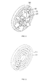
- the frame member 20 is configured such that a plurality of hollow plates having a diameter smaller than that of the flange 10, respectively, and spaced at a predetermined distance wherein their diameters are decreased gradually toward a center of the flange 10, as shown in FIG. 3 .
- the frame member 20 may be configured such that the other side is rolled to describe a circle toward a center while one side is in contact with an inner peripheral surface of the flange 10, as shown in FIG. 4 .
- the diffusion plate 30 is arranged to partition the inner part of the flange 10 for diffusing the reduction agent discharged through an injector.
- the diffusion plate 30 is configured such that the other side end is directed toward a center of the flange 10 while one side end is in contact with an internal peripheral surface of the flange 10 wherein a plurality of the diffusion plates are spaced at a predetermined distance along a circumferential direction of the flange 10, thereby partitioning the inner part of the flange into several parts.
- wings are attached to the diffusion plate 30, respectively, to make the swirl of the exhaust gas passed through the mixing device, thereby increasing the mixing property of the exhaust gas and the reduction agent.
- the wing 40 that is bent in clockwise or counter clockwise to have a predetermined angle with respect to the diffusion plate 30 is formed integrally with the diffusion plate 30 so that the exhaust gas passing through the inner side of the flange 10 is swirled.
- the wing 40 protrudes toward a rear of the mixing device formed integrally with the diffusion plate 30 while it is bent in a clockwise or a counter clockwise so that the exhaust gas passing through the mixing device is swirled at a rear of the mixing device, thereby mixing efficiently the exhaust gas and the reduction agent.
- a first wing 41 that is bent in a clockwise and a second wing 42 that is bent in a counter clockwise while having a predetermined angle with respect to the diffusion plate 30 are formed integrally with the diffusion plate 30 so that the exhaust gas passing through the inner part of the flange 10 is swirled.
- lengths and angles of the respective wings formed integrally with the diffusion plate 30 with respect to the diffusion plate may be adjusted to control a diffusion extent of the exhaust gas and the reduction agent.
- the exhaust gas discharged from an exhaust gas port of a cylinder head is transferred to the exhaust gas system through an exhaust gas manifold.
- the swirl is induced at a rear of the mixing device while the reduction agent and the exhaust gas pass through the mixing device, thereby enforcing the mixing property of the exhaust gas and the reduction agent.
- the mixing device for an exhaust gas is installed within an exhaust gas pipe of an engine, the exhaust gas and a reduction agent are diffused evenly and an even mixing of them is induced.
- the mixing device for an exhaust gas the exhaust gas that passes through the mixing device is induced to be swirled doubly and a turbulence form by the double of swirls accelerates atomization of the diffused particles of the reduction agent and particle vaporization effect, thereby enforcing the mixing property of the exhaust gas and the reduction agent.
Landscapes
- Chemical & Material Sciences (AREA)
- Engineering & Computer Science (AREA)
- Chemical Kinetics & Catalysis (AREA)
- Dispersion Chemistry (AREA)
- Combustion & Propulsion (AREA)
- Health & Medical Sciences (AREA)
- Analytical Chemistry (AREA)
- Environmental & Geological Engineering (AREA)
- Biomedical Technology (AREA)
- General Chemical & Material Sciences (AREA)
- Oil, Petroleum & Natural Gas (AREA)
- Toxicology (AREA)
- Mechanical Engineering (AREA)
- General Engineering & Computer Science (AREA)
- Exhaust Gas After Treatment (AREA)
- Exhaust Gas Treatment By Means Of Catalyst (AREA)
- Exhaust Silencers (AREA)
Abstract
Description
- This application claims under 35 U.S.C. §119(a) the benefit of Korean Patent Application No. filed the entire contents of which are incorporated herein by reference.
- The present invention relates to a mixing device for an exhaust gas in an automobile, and more particularly, to a mixing device for an exhaust gas, capable of increasing a mixing property between the exhaust gas and a reducing agent by making the exhaust gas that passes through the mixing device be swirled doubly.
- Generally, an exhaust gas discharged from an engine through an exhaust manifold is guided to a Diesel Particulate Filter (Hereinafter, referred to as "DPF"), a Selective Catalystic Reduction device (Hereinafter, referred to as "SCR device"), or a NOx Storage Reduction catalyst (Hereinafter, referred to as "NSR catalyst"), which are provided on an exhaust gas pipe, and is purified, and further noise of the exhaust gas is attenuated while passing through a muffler and then the exhaust gas is discharged outside through a tail pipe.
- Here, urea used generally as a reduction agent in the SCR device to be applied to an automobile among them is injected in a liquid drop state of a liquid into a discharged gas through an injector wherein an atomization degree of liquid and uniformity degree at a front end of catalyst affect a purification performance of NOx. That is, when an exhaust gas is swirled at a low level and the amount thereof is small, the urea is distributed unevenly to deteriorate a catalyst performance.
- At this time, a diffusion device 1 for mixing the urea is provided on a discharging pipe in order to distribute uniformly the urea used as a reduction agent to improve a mixing property of the urea, as shown in
FIG. 1 wherein in the prior diffusion device an exhaust gas flows to one direction and further the exhaust gas and the reduction agent are mixed through swirl at a rear end of the diffusion device. - However, according to the related art, the flow of the exhaust gas is defined as one direction and thus a secondary mixing property is not induced in the prior diffusion device, thereby deteriorating the mixing property.
- The items described as the background art are provided just to help understanding of the background of the present invention, and shall not be construed to admit that they correspond to the technologies already known to those skilled in the art to which the present invention pertains.
- The present invention has been made in an effort to solve the above-described problems associated with prior art. An object of the present invention is to provide a mixing device for an exhaust gas, capable of installing the mixing device for an exhaust gas within an exhaust gas pipe of an engine, diffusing evenly the exhaust gas and a reduction agent and inducing an even mixing of them. Specially, according to the mixing device for an exhaust gas, the exhaust gas that passes through the mixing device is induced to be swirled doubly and a turbulence form by the double of swirls accelerates atomization of the diffused particles of the reduction agent and particle vaporization effect, thereby enforcing the mixing property of the exhaust gas and the reduction agent.
- According to one aspect of the present invention, the mixing device for an exhaust gas includes: a hollow plate-typed flange that is arranged on a flow path of the exhaust gas; a frame member a diameter of which decreases gradually toward a center of the flange; and a diffusion plate that partitions the inner part of the flange and diffuses the exhaust gas and a reduction agent injected through a injector.
- The frame member is configured such that a plurality of hollow plates having diameters which become smaller gradually toward a center of the flange are spaced at a predetermined distance.
- The frame member is configured such that the other side is rolled to describe a circle toward a center while one side is in contact with an inner peripheral surface of the flange.
- The diffusion plate is configured such that the other side end is directed toward a center of the flange while one side end is in contact with an internal peripheral surface of the flange wherein a plurality of the diffusion plates are spaced at a predetermined distance along a circumferential direction of the flange.
- Wings each of which is bent in clockwise or counter clockwise to have a predetermined angle with respect to the diffusion plate is formed integrally with the diffusion plate so that the exhaust gas passing through the inner side of the flange is swirled.
- A first wing that is bent in a clockwise and a second wing that is bent in a counter clockwise while having a predetermined angle with respect to the diffusion plate are formed integrally with the diffusion plate so that the exhaust gas passing through the inner part of the flange is swirled.
- The above and other features of the present invention will now be described in detail with reference to certain exemplary embodiments thereof illustrated in the accompanying drawings which are given hereinbelow by way of illustration only, and thus are not limitative of the present invention, and wherein:
-
FIG. 1 is a perspective view illustrating a mixing device for exhaust gas in an automobile according to a related art; -
FIG. 2 is a perspective view illustrating a mixing device for exhaust gas according to an exemplary embodiment of the present invention; -
FIG. 3 is a perspective view illustrating a frame member according to an exemplary embodiment of the present invention; -
FIG. 4 is a perspective view illustrating a frame member according to another embodiment of the present invention; -
FIG. 5 is a perspective view illustrating a wing provided on a diffusion plate according to an exemplary embodiment of the present invention; -
FIG. 6 is a perspective view illustrating a wing provided on a diffusion plate according to another exemplary embodiment of the present invention; -
FIG. 7 is a view illustrating a state where a double of swirls of exhaust gas passed through a mixing device for exhaust gas are formed according to an exemplary embodiment of the present invention; and -
FIG. 8 is a view illustrating a flow of exhaust gas at front and rear ends of the mixing device for exhaust gas according to an exemplary embodiment of the present invention. - It should be understood that the appended drawings are not necessarily to scale, presenting a somewhat simplified representation of various preferred features illustrative of the basic principles of the invention. The specific design features of the present invention as disclosed herein, including, for example, specific dimensions, orientations, locations, and shapes will be determined in part by the particular intended application and use environment.
- In the figures, reference numbers refer to the same or equivalent parts of the present invention throughout the several figures of the drawing.
- A thickness of lines and sizes of elements are exasperated for clarity and convenience for describing the invention. Further, the terminology used herein is for the purpose of describing particular embodiments only and is not intended to be limiting of example embodiments
- Hereinafter, a mixing device for exhaust gas according to an exemplary embodiment of the present invention will be described with reference to the accompanying drawings..
- The mixing device for an exhaust gas is arranged in an exhaust gas pipe of an engine to induce uniform mixing of an exhaust gas and a reduction agent by diffusing evenly them and further make a double of swirls of the exhaust gas passed through the mixing device, thereby increasing a mixing property of the exhaust gas and the reduction agent.
- Prior to describing the mixing device for an exhaust gas in detail according to the present invention, the mixing device may be varied in size so that it may be installed at any places within an exhaust gas pipe of an engine and further it may be provided as an insertion type or a fixing type. Specially, the fixing device may be arranged at a place where a flow of an exhaust gas is focused or a reduction agent needs to be diffused evenly according to a layout of an exhaust gas system.
- Further, in describing the present invention, a front means a direction to which an exhaust gas is input to the mixing device and a rear means a direction to which the exhaust gas passes though the mixing device.
-
FIG. 2 is a perspective view illustrating a mixing device for an exhaust gas according to an exemplary embodiment of the present invention,FIG. 3 is a perspective view illustrating a frame member according to an exemplary embodiment of the present invention,FIG. 4 is a perspective view illustrating a frame member according to another embodiment of the present invention,FIG. 5 is a perspective view illustrating a wing provided on a diffusion plate according to an exemplary embodiment of the present invention,FIG. 6 is a perspective view illustrating a wing provided on a diffusion plate according to another exemplary embodiment of the present invention,FIG. 7 is a view illustrating a state where a double swirls of the exhaust gas passed through a mixing device for an exhaust gas are formed according to an exemplary embodiment of the present invention, andFIG. 8 is a view illustrating a flow of an exhaust gas at front and rear ends of the mixing device for an exhaust gas according to an exemplary embodiment of the present invention. - As shown in
FIGS. 2 to 8 , the mixing device that is arranged within an exhaust gas pipe and increases a mixing property of the exhaust gas and a reduction agent includes a hollow plate-typed flange that is arranged on a flow path of the exhaust gas, a frame member that is arranged at an inner part of the flange, and a diffusion plate that partitions the inner part of the flange wherein a wing is formed integrally with the diffusion plate to induce even mixing of the exhaust gas and the reduction agent by diffusing evenly them. - The
flange 10 is formed as circular hollow plate type and is provided at an inner part of an exhaust gas pipe through which the exhaust gas flows. - Further, diameters of the
frame member 20 decrease gradually toward inner part center of theflange 10. - That is, the
frame member 20 is configured such that a plurality of hollow plates having a diameter smaller than that of theflange 10, respectively, and spaced at a predetermined distance wherein their diameters are decreased gradually toward a center of theflange 10, as shown inFIG. 3 . - Further, the
frame member 20 may be configured such that the other side is rolled to describe a circle toward a center while one side is in contact with an inner peripheral surface of theflange 10, as shown inFIG. 4 . - Furthermore, the
diffusion plate 30 is arranged to partition the inner part of theflange 10 for diffusing the reduction agent discharged through an injector. - That is, the
diffusion plate 30 is configured such that the other side end is directed toward a center of theflange 10 while one side end is in contact with an internal peripheral surface of theflange 10 wherein a plurality of the diffusion plates are spaced at a predetermined distance along a circumferential direction of theflange 10, thereby partitioning the inner part of the flange into several parts. - Further, wings are attached to the
diffusion plate 30, respectively, to make the swirl of the exhaust gas passed through the mixing device, thereby increasing the mixing property of the exhaust gas and the reduction agent. - As one example, as shown in
FIG. 5 , thewing 40 that is bent in clockwise or counter clockwise to have a predetermined angle with respect to thediffusion plate 30 is formed integrally with thediffusion plate 30 so that the exhaust gas passing through the inner side of theflange 10 is swirled. - That is, the
wing 40 protrudes toward a rear of the mixing device formed integrally with thediffusion plate 30 while it is bent in a clockwise or a counter clockwise so that the exhaust gas passing through the mixing device is swirled at a rear of the mixing device, thereby mixing efficiently the exhaust gas and the reduction agent. - As another example, as show in
FIG. 6 , afirst wing 41 that is bent in a clockwise and a second wing 42 that is bent in a counter clockwise while having a predetermined angle with respect to thediffusion plate 30 are formed integrally with thediffusion plate 30 so that the exhaust gas passing through the inner part of theflange 10 is swirled. - That is, when the exhaust gas passes through the
first wing 41 and thesecond wing 45 formed integrally with thediffusion plate 30 of the mixing device of the present invention, a double of swirls produced at a rear of the mixing device are flowed in an opposite direction, thereby enforcing the mixing property of the exhaust gas and the reduction agent wherein the double of swirls are collided each other to form turbulence, thereby further accelerating atomization of the diffused particles of the reduction agent and particle vaporization effect. - Here, lengths and angles of the respective wings formed integrally with the
diffusion plate 30 with respect to the diffusion plate may be adjusted to control a diffusion extent of the exhaust gas and the reduction agent. - Referring to an operation and effects of the mixing device for an exhaust gas according to the present invention, first, a size of the mixing device, lengths of the wings formed integrally with the diffusion plate, and the angle between the wing and the diffusion plate are adjusted properly in accordance to air displacement of an automobile engine and a layout of an exhaust gas system and then they are installed on an exhaust gas pipe.
- The exhaust gas discharged from an exhaust gas port of a cylinder head is transferred to the exhaust gas system through an exhaust gas manifold.
- Further, when the reduction agent in a liquid drop state is diffused from an injector in order to purify the exhaust gas, the swirl is induced at a rear of the mixing device while the reduction agent and the exhaust gas pass through the mixing device, thereby enforcing the mixing property of the exhaust gas and the reduction agent.
- Furthermore, when the wings formed integrally with the diffusion plate are bent in a clockwise and a counter clockwise, a double of swirls each formed in an opposite direction are flowed at a rear of the mixing device, thereby enforcing further the mixing property of the exhaust gas and the reduction agent and the double of swirls are collided each other to form turbulence, thereby further accelerating atomization of the diffused particles of the reduction agent and particle vaporization effect.
- According to the present invention, the mixing device for an exhaust gas is installed within an exhaust gas pipe of an engine, the exhaust gas and a reduction agent are diffused evenly and an even mixing of them is induced. Specially, according to the mixing device for an exhaust gas, the exhaust gas that passes through the mixing device is induced to be swirled doubly and a turbulence form by the double of swirls accelerates atomization of the diffused particles of the reduction agent and particle vaporization effect, thereby enforcing the mixing property of the exhaust gas and the reduction agent.
- While the present invention has been illustrated and described with reference to specific embodiments, it is apparent to those skilled in the art to which the present invention pertains that the present invention may be variously improved and changed without departing from the scope of the present invention.
Claims (6)
- A mixing device for an exhaust gas, comprising:a hollow plate-typed flange that is arranged on a flow path of the exhaust gas;a frame member a diameter of which decreases gradually toward a center of the flange; anda diffusion plate that partitions the inner part of the flange and diffuses the exhaust gas and a reduction agent injected through a injector.
- The mixing device for an exhaust gas of claim 1, wherein the frame member is configured such that a plurality of hollow plates having diameters which become smaller gradually toward a center of the flange are spaced at a predetermined distance.
- The mixing device for an exhaust gas of claim 1, wherein the frame member is configured such that the other side is rolled to describe a circle toward a center while one side is in contact with an inner peripheral surface of the flange.
- The mixing device for an exhaust gas of claim 1, wherein the diffusion plate is configured such that the other side end is directed toward a center of the flange while one side end is in contact with an internal peripheral surface of the flange wherein a plurality of the diffusion plates are spaced at a predetermined distance along a circumferential direction of the flange.
- The mixing device of claim 4, wherein wings each of which is bent in clockwise or counter clockwise to have a predetermined angle with respect to the diffusion plate are formed integrally with the diffusion plate so that the exhaust gas passing through the inner side of the flange is swirled.
- The mixing device of claim 4, wherein a first wing that is bent in a clockwise and a second wing that is bent in a counter clockwise while having a predetermined angle with respect to the diffusion plate are formed integrally with the diffusion plate so that the exhaust gas passing through the inner part of the flange is swirled.
Applications Claiming Priority (1)
| Application Number | Priority Date | Filing Date | Title |
|---|---|---|---|
| KR1020110122359A KR101316407B1 (en) | 2011-11-22 | 2011-11-22 | Mixing device for exhaust gas in automobile |
Publications (2)
| Publication Number | Publication Date |
|---|---|
| EP2596854A1 true EP2596854A1 (en) | 2013-05-29 |
| EP2596854B1 EP2596854B1 (en) | 2015-07-15 |
Family
ID=47227559
Family Applications (1)
| Application Number | Title | Priority Date | Filing Date |
|---|---|---|---|
| EP12192368.4A Active EP2596854B1 (en) | 2011-11-22 | 2012-11-13 | Mixing device for exhaust gas in automobile |
Country Status (3)
| Country | Link |
|---|---|
| EP (1) | EP2596854B1 (en) |
| KR (1) | KR101316407B1 (en) |
| CN (1) | CN103133096B (en) |
Cited By (7)
| Publication number | Priority date | Publication date | Assignee | Title |
|---|---|---|---|---|
| CN109351184A (en) * | 2018-11-30 | 2019-02-19 | 李宜立 | Compound mixing arrangement, SCR denitration equipment and compound spray ammonia mixed method |
| DE102017216993B3 (en) | 2017-09-26 | 2019-02-21 | Bayerische Motoren Werke Aktiengesellschaft | mixing device |
| EP3411135A4 (en) * | 2016-12-12 | 2019-09-18 | Canada Pipeline Accessories, Co. Ltd. | STATIC MIXER FOR FLUID FLOW IN A PIPELINE |
| GB2566385B (en) * | 2016-05-02 | 2021-12-08 | Caterpillar Inc | Mixer for exhaust aftertreatment systems |
| WO2022037156A1 (en) * | 2020-08-18 | 2022-02-24 | 无锡威孚力达催化净化器有限责任公司 | Mixing apparatus having transversely arranged dual cyclone tubes |
| USD976384S1 (en) | 2020-01-13 | 2023-01-24 | Canada Pipeline Accessories Co., Ltd. | Static mixer for fluid flow |
| US11746960B2 (en) | 2018-05-07 | 2023-09-05 | Canada Pipeline Accessories Co., Ltd. | Pipe assembly with static mixer and flow conditioner |
Families Citing this family (10)
| Publication number | Priority date | Publication date | Assignee | Title |
|---|---|---|---|---|
| DE102014208743A1 (en) * | 2014-05-09 | 2015-11-12 | Robert Bosch Gmbh | Device, exhaust aftertreatment device |
| KR101498178B1 (en) * | 2014-11-25 | 2015-03-04 | 세종공업 주식회사 | Urea mixing apparatus having swirl unit |
| US9534525B2 (en) * | 2015-05-27 | 2017-01-03 | Tenneco Automotive Operating Company Inc. | Mixer assembly for exhaust aftertreatment system |
| US10012125B2 (en) | 2016-05-02 | 2018-07-03 | Caterpillar Inc. | Dual mixer for exhaust aftertreatment systems |
| CN107795359B (en) * | 2016-09-07 | 2021-04-02 | 天纳克(苏州)排放系统有限公司 | Mixing chamber assembly |
| TR201618641A2 (en) * | 2016-12-15 | 2018-07-23 | Ford Otomotiv Sanayi As | STAGE MIXER |
| KR102208899B1 (en) * | 2019-08-30 | 2021-01-28 | 세종공업 주식회사 | Reducing agent mixing apparatus having swirl unit rotating in two directions |
| CN114180070B (en) * | 2021-12-10 | 2026-02-03 | 中国商用飞机有限责任公司 | Bidirectional rotational flow mixing device for air source system heat exchanger |
| CN115030803B (en) * | 2022-06-28 | 2023-12-15 | 潍柴动力股份有限公司 | Mixer and diesel engine |
| KR102517426B1 (en) * | 2023-01-17 | 2023-04-03 | (주)제하 | Mixing device in vehicle exhaust system |
Citations (4)
| Publication number | Priority date | Publication date | Assignee | Title |
|---|---|---|---|---|
| US1113041A (en) * | 1914-05-12 | 1914-10-06 | John J Murphy | Gaseous-fuel mixer |
| DE102007009890A1 (en) * | 2007-02-28 | 2008-09-04 | Arvinmeritor Emissions Technologies Gmbh | Static mixing element, particularly arrangement in exhaust gas system of internal combustion engine, has grid-like component through which exhaust gas flows and component is formed in single-piece |
| DE102007012790A1 (en) * | 2007-03-16 | 2008-09-18 | Audi Ag | Static mixer for exhaust gas system of internal combustion engine, has carrier elements arranged around mixing axis, and flow control elements formed on carrier elements in blade-like manner, where control elements comprise slot-like notch |
| DE102008029809A1 (en) * | 2008-06-24 | 2009-12-31 | Emcon Technologies Germany (Augsburg) Gmbh | Static mixing element for exhaust system arrangement of internal combustion engine for mixing nitrogen oxides exhaust gas stream with aqueous carbamide solution, has deviation elements extending from lattice-like component to center |
Family Cites Families (2)
| Publication number | Priority date | Publication date | Assignee | Title |
|---|---|---|---|---|
| KR100836416B1 (en) | 2006-12-06 | 2008-06-09 | 현대자동차주식회사 | Urea solution disperser |
| JP2009041371A (en) | 2007-08-06 | 2009-02-26 | Bosch Corp | Exhaust emission control device and mixer unit of internal combustion engine |
-
2011
- 2011-11-22 KR KR1020110122359A patent/KR101316407B1/en active Active
-
2012
- 2012-11-13 EP EP12192368.4A patent/EP2596854B1/en active Active
- 2012-11-22 CN CN201210478420.1A patent/CN103133096B/en active Active
Patent Citations (4)
| Publication number | Priority date | Publication date | Assignee | Title |
|---|---|---|---|---|
| US1113041A (en) * | 1914-05-12 | 1914-10-06 | John J Murphy | Gaseous-fuel mixer |
| DE102007009890A1 (en) * | 2007-02-28 | 2008-09-04 | Arvinmeritor Emissions Technologies Gmbh | Static mixing element, particularly arrangement in exhaust gas system of internal combustion engine, has grid-like component through which exhaust gas flows and component is formed in single-piece |
| DE102007012790A1 (en) * | 2007-03-16 | 2008-09-18 | Audi Ag | Static mixer for exhaust gas system of internal combustion engine, has carrier elements arranged around mixing axis, and flow control elements formed on carrier elements in blade-like manner, where control elements comprise slot-like notch |
| DE102008029809A1 (en) * | 2008-06-24 | 2009-12-31 | Emcon Technologies Germany (Augsburg) Gmbh | Static mixing element for exhaust system arrangement of internal combustion engine for mixing nitrogen oxides exhaust gas stream with aqueous carbamide solution, has deviation elements extending from lattice-like component to center |
Cited By (12)
| Publication number | Priority date | Publication date | Assignee | Title |
|---|---|---|---|---|
| GB2566385B (en) * | 2016-05-02 | 2021-12-08 | Caterpillar Inc | Mixer for exhaust aftertreatment systems |
| EP3411135A4 (en) * | 2016-12-12 | 2019-09-18 | Canada Pipeline Accessories, Co. Ltd. | STATIC MIXER FOR FLUID FLOW IN A PIPELINE |
| US10619797B2 (en) | 2016-12-12 | 2020-04-14 | Canada Pipeline Accessories, Co., Ltd. | Static mixer for fluid flow in a pipeline |
| US11224846B2 (en) | 2016-12-12 | 2022-01-18 | Canada Pipeline Accessories Co., Ltd. | Static mixer for fluid flow in a pipeline |
| EP3967392A1 (en) * | 2016-12-12 | 2022-03-16 | Canada Pipeline Accessories, Co. Ltd. | Static mixer for fluid flow in a pipeline |
| DE102017216993B3 (en) | 2017-09-26 | 2019-02-21 | Bayerische Motoren Werke Aktiengesellschaft | mixing device |
| US11746960B2 (en) | 2018-05-07 | 2023-09-05 | Canada Pipeline Accessories Co., Ltd. | Pipe assembly with static mixer and flow conditioner |
| CN109351184A (en) * | 2018-11-30 | 2019-02-19 | 李宜立 | Compound mixing arrangement, SCR denitration equipment and compound spray ammonia mixed method |
| CN109351184B (en) * | 2018-11-30 | 2024-04-09 | 浙江大维高新技术股份有限公司 | Composite mixing device, SCR denitration equipment and composite ammonia spraying mixing method |
| USD976384S1 (en) | 2020-01-13 | 2023-01-24 | Canada Pipeline Accessories Co., Ltd. | Static mixer for fluid flow |
| USD992107S1 (en) | 2020-01-13 | 2023-07-11 | Canada Pipeline Accessories Co., Ltd. | Static mixer |
| WO2022037156A1 (en) * | 2020-08-18 | 2022-02-24 | 无锡威孚力达催化净化器有限责任公司 | Mixing apparatus having transversely arranged dual cyclone tubes |
Also Published As
| Publication number | Publication date |
|---|---|
| CN103133096B (en) | 2016-12-21 |
| KR20130056643A (en) | 2013-05-30 |
| EP2596854B1 (en) | 2015-07-15 |
| KR101316407B1 (en) | 2013-10-08 |
| CN103133096A (en) | 2013-06-05 |
Similar Documents
| Publication | Publication Date | Title |
|---|---|---|
| EP2596854B1 (en) | Mixing device for exhaust gas in automobile | |
| US10711677B2 (en) | Exhaust aftertreatment system having mixer assembly | |
| US11193412B2 (en) | Automotive exhaust aftertreatment system | |
| EP3279440B1 (en) | Exhaust purification unit | |
| US10100700B2 (en) | Cantilevered flow distributing apparatus | |
| US7793490B2 (en) | Exhaust gas system for diesel vehicles with an SCR catalytic converter | |
| CN103114892A (en) | Assembly for mixing liquid within gas flow | |
| WO2019045701A1 (en) | Venturi style injector cone | |
| CN105089750A (en) | Exhaust gas treatment device | |
| JP5104960B2 (en) | Exhaust gas purification device for internal combustion engine | |
| CN108150247A (en) | Exhaust after treatment system, device and method | |
| CN204877615U (en) | Exhaust treatment appts | |
| CN104832255B (en) | Two-layer hybrid pipe and its exhaust gas treatment device | |
| JP2018123788A (en) | Exhaust gas purification device | |
| US10392989B1 (en) | Automotive exhaust aftertreatment system having an ammonia distributor | |
| EP3198122A1 (en) | Exhaust gas reduction unit for internal combustion engine | |
| CN206987927U (en) | Exhaust aftertreatment mixing arrangement and its encapsulation | |
| CN105705742B (en) | Exhaust treatment unit with shunting and mixed guiding part | |
| US20250327414A1 (en) | Exhaust mixer assembly | |
| KR101744797B1 (en) | Apparatus for mixing reducing agent | |
| CN109236430A (en) | Exhaust aftertreatment mixing arrangement and its encapsulation | |
| US9174167B2 (en) | Mixing plate providing reductant distribution | |
| EP2716884A1 (en) | Exhaust purification device for internal combustion engine | |
| CN112324548A (en) | Tail gas aftertreatment encapsulation | |
| JP7752768B2 (en) | exhaust purification device |
Legal Events
| Date | Code | Title | Description |
|---|---|---|---|
| PUAI | Public reference made under article 153(3) epc to a published international application that has entered the european phase |
Free format text: ORIGINAL CODE: 0009012 |
|
| AK | Designated contracting states |
Kind code of ref document: A1 Designated state(s): AL AT BE BG CH CY CZ DE DK EE ES FI FR GB GR HR HU IE IS IT LI LT LU LV MC MK MT NL NO PL PT RO RS SE SI SK SM TR |
|
| AX | Request for extension of the european patent |
Extension state: BA ME |
|
| 17P | Request for examination filed |
Effective date: 20130905 |
|
| RBV | Designated contracting states (corrected) |
Designated state(s): AL AT BE BG CH CY CZ DE DK EE ES FI FR GB GR HR HU IE IS IT LI LT LU LV MC MK MT NL NO PL PT RO RS SE SI SK SM TR |
|
| 17Q | First examination report despatched |
Effective date: 20131028 |
|
| GRAP | Despatch of communication of intention to grant a patent |
Free format text: ORIGINAL CODE: EPIDOSNIGR1 |
|
| GRAJ | Information related to disapproval of communication of intention to grant by the applicant or resumption of examination proceedings by the epo deleted |
Free format text: ORIGINAL CODE: EPIDOSDIGR1 |
|
| RIC1 | Information provided on ipc code assigned before grant |
Ipc: F01N 3/20 20060101ALN20141020BHEP Ipc: B01F 5/06 20060101AFI20141020BHEP |
|
| INTG | Intention to grant announced |
Effective date: 20141114 |
|
| INTC | Intention to grant announced (deleted) | ||
| RIC1 | Information provided on ipc code assigned before grant |
Ipc: B01F 5/06 20060101AFI20141124BHEP Ipc: F01N 3/20 20060101ALN20141124BHEP |
|
| GRAP | Despatch of communication of intention to grant a patent |
Free format text: ORIGINAL CODE: EPIDOSNIGR1 |
|
| INTG | Intention to grant announced |
Effective date: 20150206 |
|
| RIC1 | Information provided on ipc code assigned before grant |
Ipc: B01F 5/06 20060101AFI20150129BHEP Ipc: F01N 3/20 20060101ALN20150129BHEP |
|
| GRAS | Grant fee paid |
Free format text: ORIGINAL CODE: EPIDOSNIGR3 |
|
| GRAA | (expected) grant |
Free format text: ORIGINAL CODE: 0009210 |
|
| AK | Designated contracting states |
Kind code of ref document: B1 Designated state(s): AL AT BE BG CH CY CZ DE DK EE ES FI FR GB GR HR HU IE IS IT LI LT LU LV MC MK MT NL NO PL PT RO RS SE SI SK SM TR |
|
| REG | Reference to a national code |
Ref country code: CH Ref legal event code: EP Ref country code: GB Ref legal event code: FG4D |
|
| REG | Reference to a national code |
Ref country code: IE Ref legal event code: FG4D |
|
| REG | Reference to a national code |
Ref country code: AT Ref legal event code: REF Ref document number: 736489 Country of ref document: AT Kind code of ref document: T Effective date: 20150815 |
|
| REG | Reference to a national code |
Ref country code: DE Ref legal event code: R096 Ref document number: 602012008764 Country of ref document: DE |
|
| REG | Reference to a national code |
Ref country code: FR Ref legal event code: PLFP Year of fee payment: 4 |
|
| REG | Reference to a national code |
Ref country code: AT Ref legal event code: MK05 Ref document number: 736489 Country of ref document: AT Kind code of ref document: T Effective date: 20150715 |
|
| REG | Reference to a national code |
Ref country code: NL Ref legal event code: MP Effective date: 20150715 |
|
| REG | Reference to a national code |
Ref country code: LT Ref legal event code: MG4D |
|
| PG25 | Lapsed in a contracting state [announced via postgrant information from national office to epo] |
Ref country code: FI Free format text: LAPSE BECAUSE OF FAILURE TO SUBMIT A TRANSLATION OF THE DESCRIPTION OR TO PAY THE FEE WITHIN THE PRESCRIBED TIME-LIMIT Effective date: 20150715 Ref country code: NO Free format text: LAPSE BECAUSE OF FAILURE TO SUBMIT A TRANSLATION OF THE DESCRIPTION OR TO PAY THE FEE WITHIN THE PRESCRIBED TIME-LIMIT Effective date: 20151015 Ref country code: LT Free format text: LAPSE BECAUSE OF FAILURE TO SUBMIT A TRANSLATION OF THE DESCRIPTION OR TO PAY THE FEE WITHIN THE PRESCRIBED TIME-LIMIT Effective date: 20150715 Ref country code: GR Free format text: LAPSE BECAUSE OF FAILURE TO SUBMIT A TRANSLATION OF THE DESCRIPTION OR TO PAY THE FEE WITHIN THE PRESCRIBED TIME-LIMIT Effective date: 20151016 Ref country code: LV Free format text: LAPSE BECAUSE OF FAILURE TO SUBMIT A TRANSLATION OF THE DESCRIPTION OR TO PAY THE FEE WITHIN THE PRESCRIBED TIME-LIMIT Effective date: 20150715 |
|
| PG25 | Lapsed in a contracting state [announced via postgrant information from national office to epo] |
Ref country code: SE Free format text: LAPSE BECAUSE OF FAILURE TO SUBMIT A TRANSLATION OF THE DESCRIPTION OR TO PAY THE FEE WITHIN THE PRESCRIBED TIME-LIMIT Effective date: 20150715 Ref country code: AT Free format text: LAPSE BECAUSE OF FAILURE TO SUBMIT A TRANSLATION OF THE DESCRIPTION OR TO PAY THE FEE WITHIN THE PRESCRIBED TIME-LIMIT Effective date: 20150715 Ref country code: PL Free format text: LAPSE BECAUSE OF FAILURE TO SUBMIT A TRANSLATION OF THE DESCRIPTION OR TO PAY THE FEE WITHIN THE PRESCRIBED TIME-LIMIT Effective date: 20150715 Ref country code: RS Free format text: LAPSE BECAUSE OF FAILURE TO SUBMIT A TRANSLATION OF THE DESCRIPTION OR TO PAY THE FEE WITHIN THE PRESCRIBED TIME-LIMIT Effective date: 20150715 Ref country code: HR Free format text: LAPSE BECAUSE OF FAILURE TO SUBMIT A TRANSLATION OF THE DESCRIPTION OR TO PAY THE FEE WITHIN THE PRESCRIBED TIME-LIMIT Effective date: 20150715 Ref country code: ES Free format text: LAPSE BECAUSE OF FAILURE TO SUBMIT A TRANSLATION OF THE DESCRIPTION OR TO PAY THE FEE WITHIN THE PRESCRIBED TIME-LIMIT Effective date: 20150715 Ref country code: PT Free format text: LAPSE BECAUSE OF FAILURE TO SUBMIT A TRANSLATION OF THE DESCRIPTION OR TO PAY THE FEE WITHIN THE PRESCRIBED TIME-LIMIT Effective date: 20151116 |
|
| REG | Reference to a national code |
Ref country code: DE Ref legal event code: R097 Ref document number: 602012008764 Country of ref document: DE |
|
| PG25 | Lapsed in a contracting state [announced via postgrant information from national office to epo] |
Ref country code: EE Free format text: LAPSE BECAUSE OF FAILURE TO SUBMIT A TRANSLATION OF THE DESCRIPTION OR TO PAY THE FEE WITHIN THE PRESCRIBED TIME-LIMIT Effective date: 20150715 Ref country code: SK Free format text: LAPSE BECAUSE OF FAILURE TO SUBMIT A TRANSLATION OF THE DESCRIPTION OR TO PAY THE FEE WITHIN THE PRESCRIBED TIME-LIMIT Effective date: 20150715 Ref country code: DK Free format text: LAPSE BECAUSE OF FAILURE TO SUBMIT A TRANSLATION OF THE DESCRIPTION OR TO PAY THE FEE WITHIN THE PRESCRIBED TIME-LIMIT Effective date: 20150715 Ref country code: CZ Free format text: LAPSE BECAUSE OF FAILURE TO SUBMIT A TRANSLATION OF THE DESCRIPTION OR TO PAY THE FEE WITHIN THE PRESCRIBED TIME-LIMIT Effective date: 20150715 Ref country code: IT Free format text: LAPSE BECAUSE OF FAILURE TO SUBMIT A TRANSLATION OF THE DESCRIPTION OR TO PAY THE FEE WITHIN THE PRESCRIBED TIME-LIMIT Effective date: 20150715 |
|
| PLBE | No opposition filed within time limit |
Free format text: ORIGINAL CODE: 0009261 |
|
| STAA | Information on the status of an ep patent application or granted ep patent |
Free format text: STATUS: NO OPPOSITION FILED WITHIN TIME LIMIT |
|
| PG25 | Lapsed in a contracting state [announced via postgrant information from national office to epo] |
Ref country code: RO Free format text: LAPSE BECAUSE OF FAILURE TO SUBMIT A TRANSLATION OF THE DESCRIPTION OR TO PAY THE FEE WITHIN THE PRESCRIBED TIME-LIMIT Effective date: 20150715 |
|
| 26N | No opposition filed |
Effective date: 20160418 |
|
| PG25 | Lapsed in a contracting state [announced via postgrant information from national office to epo] |
Ref country code: MC Free format text: LAPSE BECAUSE OF FAILURE TO SUBMIT A TRANSLATION OF THE DESCRIPTION OR TO PAY THE FEE WITHIN THE PRESCRIBED TIME-LIMIT Effective date: 20150715 Ref country code: IS Free format text: LAPSE BECAUSE OF FAILURE TO SUBMIT A TRANSLATION OF THE DESCRIPTION OR TO PAY THE FEE WITHIN THE PRESCRIBED TIME-LIMIT Effective date: 20150715 Ref country code: LU Free format text: LAPSE BECAUSE OF FAILURE TO SUBMIT A TRANSLATION OF THE DESCRIPTION OR TO PAY THE FEE WITHIN THE PRESCRIBED TIME-LIMIT Effective date: 20151113 |
|
| REG | Reference to a national code |
Ref country code: CH Ref legal event code: PL |
|
| PG25 | Lapsed in a contracting state [announced via postgrant information from national office to epo] |
Ref country code: LI Free format text: LAPSE BECAUSE OF NON-PAYMENT OF DUE FEES Effective date: 20151130 Ref country code: CH Free format text: LAPSE BECAUSE OF NON-PAYMENT OF DUE FEES Effective date: 20151130 |
|
| REG | Reference to a national code |
Ref country code: IE Ref legal event code: MM4A |
|
| PG25 | Lapsed in a contracting state [announced via postgrant information from national office to epo] |
Ref country code: SI Free format text: LAPSE BECAUSE OF FAILURE TO SUBMIT A TRANSLATION OF THE DESCRIPTION OR TO PAY THE FEE WITHIN THE PRESCRIBED TIME-LIMIT Effective date: 20150715 |
|
| REG | Reference to a national code |
Ref country code: FR Ref legal event code: PLFP Year of fee payment: 5 |
|
| PG25 | Lapsed in a contracting state [announced via postgrant information from national office to epo] |
Ref country code: IE Free format text: LAPSE BECAUSE OF NON-PAYMENT OF DUE FEES Effective date: 20151113 |
|
| PG25 | Lapsed in a contracting state [announced via postgrant information from national office to epo] |
Ref country code: BE Free format text: LAPSE BECAUSE OF FAILURE TO SUBMIT A TRANSLATION OF THE DESCRIPTION OR TO PAY THE FEE WITHIN THE PRESCRIBED TIME-LIMIT Effective date: 20150715 |
|
| PG25 | Lapsed in a contracting state [announced via postgrant information from national office to epo] |
Ref country code: SM Free format text: LAPSE BECAUSE OF FAILURE TO SUBMIT A TRANSLATION OF THE DESCRIPTION OR TO PAY THE FEE WITHIN THE PRESCRIBED TIME-LIMIT Effective date: 20150715 Ref country code: BG Free format text: LAPSE BECAUSE OF FAILURE TO SUBMIT A TRANSLATION OF THE DESCRIPTION OR TO PAY THE FEE WITHIN THE PRESCRIBED TIME-LIMIT Effective date: 20150715 Ref country code: HU Free format text: LAPSE BECAUSE OF FAILURE TO SUBMIT A TRANSLATION OF THE DESCRIPTION OR TO PAY THE FEE WITHIN THE PRESCRIBED TIME-LIMIT; INVALID AB INITIO Effective date: 20121113 |
|
| PG25 | Lapsed in a contracting state [announced via postgrant information from national office to epo] |
Ref country code: NL Free format text: LAPSE BECAUSE OF FAILURE TO SUBMIT A TRANSLATION OF THE DESCRIPTION OR TO PAY THE FEE WITHIN THE PRESCRIBED TIME-LIMIT Effective date: 20150715 Ref country code: CY Free format text: LAPSE BECAUSE OF FAILURE TO SUBMIT A TRANSLATION OF THE DESCRIPTION OR TO PAY THE FEE WITHIN THE PRESCRIBED TIME-LIMIT Effective date: 20150715 |
|
| PG25 | Lapsed in a contracting state [announced via postgrant information from national office to epo] |
Ref country code: MT Free format text: LAPSE BECAUSE OF FAILURE TO SUBMIT A TRANSLATION OF THE DESCRIPTION OR TO PAY THE FEE WITHIN THE PRESCRIBED TIME-LIMIT Effective date: 20150715 |
|
| REG | Reference to a national code |
Ref country code: FR Ref legal event code: PLFP Year of fee payment: 6 |
|
| PG25 | Lapsed in a contracting state [announced via postgrant information from national office to epo] |
Ref country code: TR Free format text: LAPSE BECAUSE OF FAILURE TO SUBMIT A TRANSLATION OF THE DESCRIPTION OR TO PAY THE FEE WITHIN THE PRESCRIBED TIME-LIMIT Effective date: 20150715 Ref country code: MK Free format text: LAPSE BECAUSE OF FAILURE TO SUBMIT A TRANSLATION OF THE DESCRIPTION OR TO PAY THE FEE WITHIN THE PRESCRIBED TIME-LIMIT Effective date: 20150715 |
|
| REG | Reference to a national code |
Ref country code: FR Ref legal event code: PLFP Year of fee payment: 7 |
|
| PG25 | Lapsed in a contracting state [announced via postgrant information from national office to epo] |
Ref country code: AL Free format text: LAPSE BECAUSE OF FAILURE TO SUBMIT A TRANSLATION OF THE DESCRIPTION OR TO PAY THE FEE WITHIN THE PRESCRIBED TIME-LIMIT Effective date: 20150715 |
|
| REG | Reference to a national code |
Ref country code: DE Ref legal event code: R079 Ref document number: 602012008764 Country of ref document: DE Free format text: PREVIOUS MAIN CLASS: B01F0005060000 Ipc: B01F0025400000 |
|
| P01 | Opt-out of the competence of the unified patent court (upc) registered |
Effective date: 20230504 |
|
| PGFP | Annual fee paid to national office [announced via postgrant information from national office to epo] |
Ref country code: DE Payment date: 20241021 Year of fee payment: 13 |
|
| PGFP | Annual fee paid to national office [announced via postgrant information from national office to epo] |
Ref country code: GB Payment date: 20241021 Year of fee payment: 13 |
|
| PGFP | Annual fee paid to national office [announced via postgrant information from national office to epo] |
Ref country code: FR Payment date: 20241022 Year of fee payment: 13 |